

Page 1
ADA-26S
STEREO AUDIO
DISTRIBUTION AMPLIFIER
INSTRUCTION MANUAL
SIGMA ELECTRONICS, INC.
P.O. Box 448
1027 COMMERCIAL AVENUE
EAST PETERSBURG, PA 17520-0448
(717) 569-2681
Page 2

ADA-26S STEREO AUDIO DISTRIBUTION AMPLIFIER
GENERAL:
The ADA-26S Stereo Audio Distribution Am plifier is designed to operate in two differ ent modes. The first
mode provides three (3) dual-channel outputs from a stereo audio signal source. The other mode provides six
(6) single-channel outputs from a m onaural audio signal sourc e. The desir ed mode c an be selected fr om the
front panel.
In either mode, the module is compatible with either balanced or unbalanced audio signals on the input
and outputs. Outputs can be mixed between balanced and unbalanced configuration dependent on the
requirement of the destination equipment.
POWER:
The ADA-26S operates from an AC power source of 120VAC or 230 VAC at line frequencies of 60 Hz or
50 Hz. The unit is supplied with an IEC 320 power inlet on the rear panel and a cordset with either a NEMA515P or CEE7/7 plug.
Internally the unit has bus voltages of +15Vdc and -15Vdc supplied by regulators U01 and U02 respectively.
An LED on the circuit board illuminates the front panel when both supplies are operating properly.
Circuit protection is provided by the externally accessible fuse on the rear panel. Refer to the specification
section for proper fuse value.
FRAMES:
The ADA-26S module is mounted within a stand-alone box. The all-metal enclosure provides desirable
shielding to external EMI/RFI noise sources.
Rack-mounting requir es the RMK-26 rack -mount k it. One RMK-26 rack -mount k it holds up to three of the 26
series units. Sigm a provides various dis tribution am plifier s, signal gener ators and trans coding produc ts in the
26 series.
CONNECTIONS:
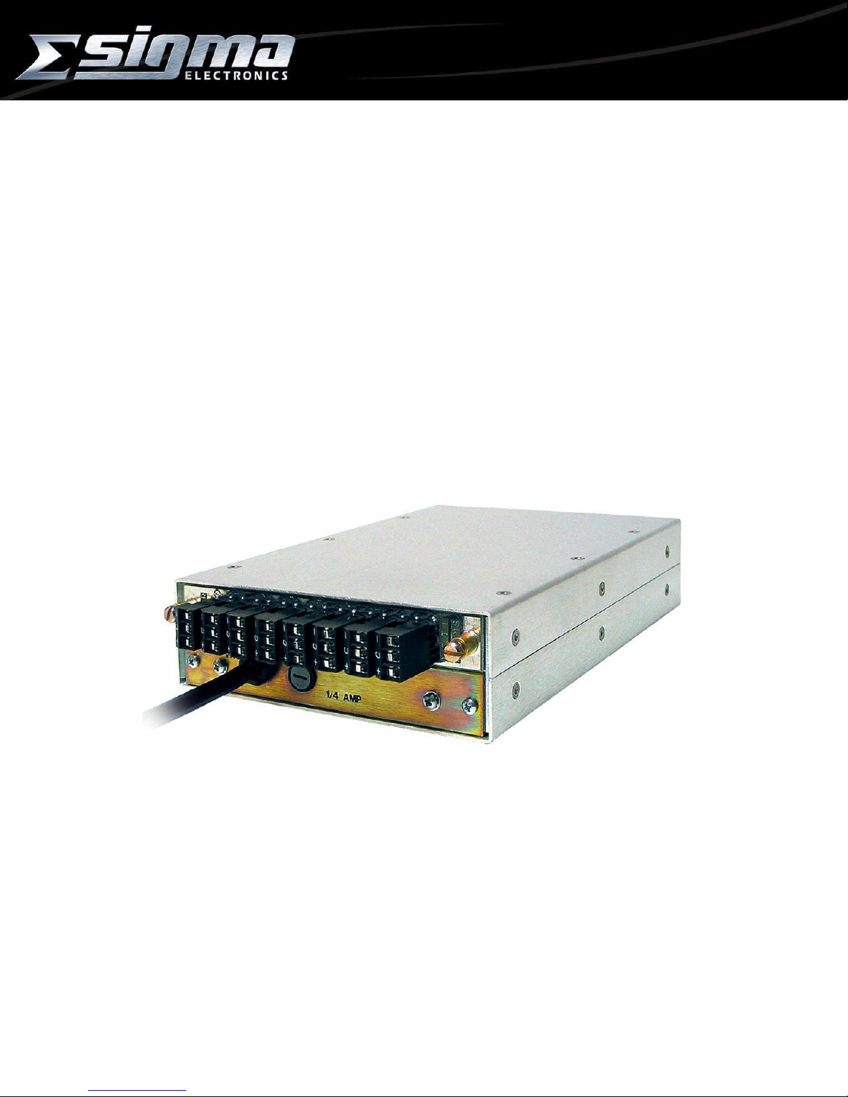
Wiring to the module is performed via detachable screw terminal connectors (Figure 1).
INPUT: There are dual-channel inputs on the rear panel of the unit; the firs t and last connectors (Figure
2). The Right channel is on the left and the Left channel is on the right as seen from the rear of the unit. When
the unit is configur ed to pr ovide s ix ( 6) outputs f r om a single input, the “Left Input” is disabled (the input on the
right).
Both inputs are a high im pedanc e conf iguration. T his allows the audio signals to be bridged to other units .
To ensure proper impedance matching it may be necessary to terminate the outputs with a 600Ω load. It is
recommended that, if termination is necessary, use a 600Ω, 1/2 watt resistor across the (+) and (-) outputs.
When multiple units have inputs bridged to the same sourc e, only apply the 600Ω resistor to the last unit in the
line.
OUTPUT: T here are three (3) outputs on the rear panel of the unit for each channel . Each output is
designed to drive a 600Ω load. Since each output on a channel is identical, the numbering is only provided for
the operator’s convenience. W hen the unit is configured to provide six (6) outputs from a single input, both
the right and left outputs will provide the same signal.
Figure 1
AUDIO CONNECTOR
ADA-26S
Doc. No. – 14480
Page 1 of 4
Page 3

ADA-26S STEREO AUDIO DISTRIBUTION AMPLIFIER
R I
I N
G P
H U
T T
120/240V~
60Hz/50Hz
12W
C
+
C
+
AUDIO CONFIGURATIONS:
The source and destination audio equipment must be evaluated to determine if they are Balanced or
Unbalanced. After determination is made, refer to the drawings provided to select the proper audio
configuration. The outputs can be any combination of balanced or unbalanced.
+
C
-
ADA-26S
+
C
-
IN OUT
Balanced In to Balanced Out Balanced In to Unbalanced Out
Vout = Vin Vout = 0.5 Vin
+
Gnd
ADA-26S
+
C
-
IN OUT
Unbalanced In to Balanced Out Unbalanced In to Unbalanced Out
(-) Input Grounded; Vout = Vin Vout = 0.5 Vin
(-) Input Floating: Vout = 0.75 Vin
The input to output level comparison pr ovided in the figures above, assumes the outputs are terminated
into a 600Ω load.
1
2
C
+
3
C
+
C
+
FUSE
T125mA/T63mA
250V
REAR PANEL CONNECTIONS
Figure 2
+
C
-
+
C
-
+
C
-
+
C
-
+
Gnd
C
+
1
C
+
T
CAUTION
RISK OF ELECTRIC SHOCK
L I
E N
F P
T U
T
3
2
C
+
ADA-26S
+
C
-
+
C
-
+
C
-
+
C
Open
IN OUT
ADA-26S
+
C
-
+
C
-
+
C
Open
IN OUT
ADA-26S
Doc. No. – 14480
Page 2 of 4
Page 4

ADA-26S STEREO AUDIO DISTRIBUTION AMPLIFIER
FRONT PANEL:
The adjustm ents and indicator s on the f ront panel (Figure 3) c an be accessed through the s lots provided
in the ADA-26S frame. Fact ory settings of the module provide unity gain, maximum com mon mode rej ection,
and a bandwidth of 100 kHz.
Gain Control - Gain control for the right channel is achieved by adjustments to S01and R012. Gain
control for the left channel is achieved by adjustments to S901and R912. S01 and S901 provide gain
adjustment in inc rem ents of 6dB, while R012 and R912 provide f ine adjustm ents of +/- 3dB. The positions of
S01 and S901 mak e the following adjus tments to the gain level of the circuit - = OFF, 1= -6dB, 2= 0dB, 3=
+6dB, 4= +12dB, 5= +18dBand 6= +24dB.
M ode Selection – To select the three (3) output ster eo m ode, set the m ode selec t switch, S02, to the lef t
position. This will activate the Left gain controls and Left Input on the r ear panel. To select the single input,
six (6) output mode, set the m ode select switch, S02, to the right position. This will deactivate the Left gain
controls and input on the rear panel.
3
2
4
1
5
6
3
2
4
1
5
6
R912
S901
S02
R012
S01
Figure 3: Front Panel Gain Adjustment
ADJUSTMENTS:
The ADA-26S has no adjustments other than the front panel gain control and mode selection.
SPECIFICATIONS:
INPUT: ...............................................Dual channel, Balanced, +24 dBm Maximum
INPUT IMPEDANCE: ........................30 kΩ Balanced, DC coupled
OUTPUT: ...........................................+24 dBm Maximum
OUTPUT IMPEDANCE: ....................100Ω Balanced, DC coupled
LEFT/RIGHT SEPARATION: ............All outputs driven into 600Ω, unused input terminated.
............................................................Greater than 80 dB, 20 Hz to 20 KHz
HUM and NOISE: ..............................less than -80 dBm at Unity Gain, 22Hz to 22Khz filter
less than -65 dBm at +27 dB Gain, 22Hz to 22Khz filter
THD+N: .............................................Into 600Ω, 22Hz to 22Khz filter, 0dBm to +24 dBm
less than 0.05% 20 Hz to 20KHz)
IND (SMPTE 4:1 60Hz/7KhZ): ..........same conditions as THD+N, less than 0.02%
GAIN RANGE: ...................................(-6) to +24 dB in 6dB steps,±3dB vernier when terminated into 600Ω.
GAIN VARIATION: ............................±0.3 dB
CMR: .................................................Greater than 70 dB at 60 Hz, 60 dB at 20 KHz
0dBm to +24dBm
RESPONSE: ......................................Into 600Ω, ±0.2 dB, 20 Hz to30 KHz
ADA-26S
Doc. No. – 14480
Page 3 of 4
Page 5

ADA-26S STEREO AUDIO DISTRIBUTION AMPLIFIER
TECHNICAL MANUAL:
A manual including schematics, circuit description, parts list and setup guide is available upon request. This
information is intended for the service of the module. Modules should be serviced by Qualified Personnel only
! Sigma Electronics, Inc. recommends service to be performed by our Factory Service Center.
NOTES:
Information is intended to give a general performance and operation guideline of the product.
Sigma Electronics, Inc.; P.O.Box 448; 1027 Commercial Avenue; East Petersburg, PA 17520-0448
Main Office: Tel: (717) 569-2681 Fax: (717) 569-4056
REV2 OCT01 ADA-26S
All specifications, drawings, dimensions, weights and other details are subject to change without notification.
ADA-26S
Doc. No. – 14480
Page 4 of 4
 Loading...