

Page 1
ADA-26A
AUDIO
DISTRIBUTION AMPLIFIER
INSTRUCTION MANUAL
SIGMA ELECTRONICS, INC.
P.O. Box 448
1027 COMMERCIAL AVENUE
EAST PETERSBURG, PA 17520-0448
(717) 569-2681
Page 2
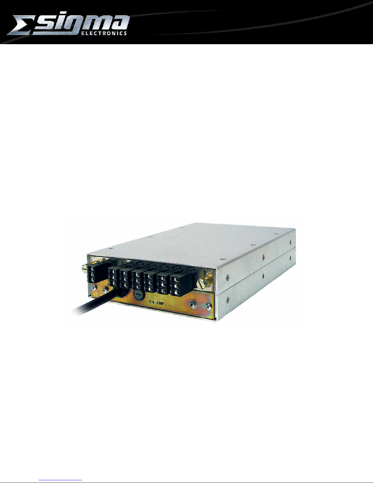
ADA-26A AUDIO DISTRIBUTION AMPLIFIER
GENERAL:
The ADA-26A Audio Distribution Amplif ier is designed to provide s ix (6) outputs f rom a single audio signal
source. The unit is com patible with either balanced or unbalanced audio signals on the input and outputs.
Outputs can be mixed between balanced and unbalanced c onfiguration dependent on the requirement of the
destination equipment.
POWER:
The ADA-26A operates from an AC power source of 120VAC or 230 VAC at line frequencies from 50 Hz to
60 Hz. The unit is supplied with a line cord terminated with a three-prong grounded plug.
Internally the unit has bus voltages of +15Vdc and -15Vdc supplied by regulators U01 and U02 respectively.
An LED on the circuit board illuminates the front panel when both supplies are operating properly.
Circuit protection is provided by the externally accessible fuse on the rear panel. Refer to the specification
section for proper fuse value.
FRAMES:
The ADA-26A module is mounted within a stand-alone box. The all-metal enclosure provides desirable
shielding to external EMI/RFI noise sources.
Rack mounting requires the RMK-26 rack -mount k it. One RMK-26 rack -mount k it holds up to three of the 26
series units. Sigma provides various distr ibution am plifier s, signal generators and transc oding produc ts in the
26 series.
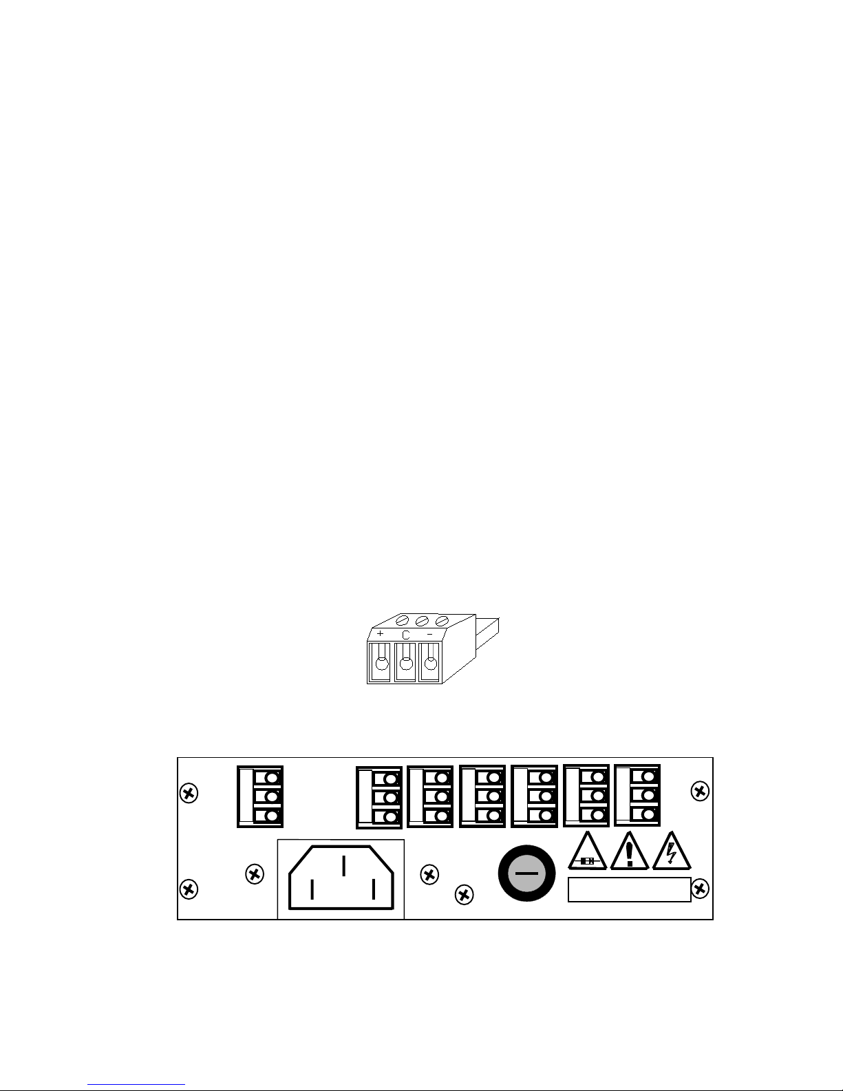
CONNECTIONS:
Wiring to the module is performed via detachable screw terminal connectors (Figure 1).
INPUT: There is a single input on the rear panel of the unit (Figure 2). The INPUT is a high impedance
configuration. This allows the audio signals to bridge to other units. To ensure proper im pedance matching it
may be necessary to terminate the outputs with a 600Ω load. For termination, it is r eco mmended that a 600Ω,
1/2 watt resistor be placed between the (+) and (-) outputs. When m ultiple units have inputs bridged to the
same source, only apply the 600Ω resistor to the last unit in the line.
OUTPUT: Ther e are s ix ( 6) outputs on the r ear panel of the unit. Eac h output is des igned to drive a 600Ω
load.
I
-
N
C
P
+
U
T
120/240V~
50/60Hz
12W
ADA-26A
Figure 1
AUDIO CONNECTOR
OP
UU
TT
S
C
+
1
C
+
2 3 4
T125mA/T63mA
C
+
FUSE
250V
C
+
C
+
5
SIGMA ELECTRONICS, INC.
C
+
T
CAUTION
RISK OF ELECTRIC SHOCK
6
REAR PANEL CONNECTIONS
Figure 2
ADA-26A Doc. No. – 13923
Page 1 of 3
Page 3

AUDIO CONFIGURATIONS:
The source and destination audio equipment must be evaluated to determine if they are Balanced or
Unbalanced. After determination is made, refer to the drawings provided to select the proper audio
configuration. The outputs can be any combination of balanced or unbalanced.
ADA-26A
+
C
-
+
C
-
+
C
-
+
C
-
+
C
-
IN OUT
ADA-26A
+
C
-
IN OUT
+
C
-
+
C
Open
Balanced In to Balanced Out Balanced In to Unbalanced Out
Vout = Vin Vout = 0.5 Vin
+
Gnd
ADA-26A
+
C
-
IN OUT
+
C
-
+
C
+
Gnd
-
ADA-26A
+
C
-
IN OUT
+
C
-
+
C
Open
Unbalanced In to Balanced Out Unbalanced In to Unbalanced Out
(-) Input Grounded; Vout = Vin Vout = 0.5 Vin
(-) Input Floating: Vout = 0.75 Vin
The input to output level comparison provided in the f igures above, assumes the outputs ar e terminated
into a 600Ω load.
FRONT PANEL:
The adjustments and indic ators on the front panel ( Figure 3) can be accessed thr ough the slots provided
in the frame in which the ADA-26A is ins talled. When mounted within the SS-2100 Series frames, it will be
necessary to remove the front panel of the frame to gain access to these items. Factory settings of the module
provide unity gain, maximum common mode rejection, and a bandwidth of 100 kHz.
Gain control is achieved by adjustments to S01and R102. S01 provides adjustment of the gain in
increments of 6dB, while R102 provides f ine adjus tm ents of +/- 3dB. T he positions of S01 m ak e the f ollowing
adjustments to the gain level of the circuit - = OFF, 1 = -6dB, 2 = 0dB, 3 = +6dB, 4 = +12dB, 5 = +18dB and
6 = +24dB.
Figure 3: Front Panel Gain Adjustment
3
2
4
1
5
6
S01R102
ADA-26A Doc. No. – 13923
Page 2 of 3
Page 4

ADA-26A AUDIO DISTRIBUTION AMPLIFIER
ADJUSTMENTS:
Common Mode Rejection and Gain are both set for optimum performance by Sigma Electronics.
AC Voltage Selection:
The primary wiring of T1 must be in accordance with the line voltage applied to the unit.
120 VAC applications. The center-tapped wires must be soldered in the 120V position. Make sure the black
wire is in the hole next to the BLK printing on the circuit board.
230 VAC applications. The center-tapped wires must be soldered in the 240V position. Make sure the black
wire is in the hole next to the BLK printing on the circuit board.
SPECIFICATIONS:
INPUT: ................................ Balanced, +24 dBm Maximum
INPUT IMPEDANCE: .......... 30 kΩ Balanced, 15 kΩ each line to ground
OUTPUT: ............................ +24 dBm Maximum
OUTPUT IMPEDANCE: ...... 150Ω Balanced
ISOLATION: ....................... 70 dB Minimum (15 kHz)
HUM and NOISE: ............... -90 dBm at Unity Gain
THD+N………………………. 0.005% 20 Hz to 20kHz (30kHz LPF)
GAIN RANGE: .................... -9 to +27 dB
CMR: .................................. 70 dB Minimum (20 Hz to 10 kHz)
60 dB Minimum (10 kHz to 20 kHz)
RESPONSE: ....................... +/- 0.2 dB Maximum to 100 kHz at Unity Gain
TECHNICAL MANUAL:
A manual including schematics, circuit description, parts list and setup guide is available upon request. This
information is intended for the service of the module. Modules should be serviced by Qualified Personnel only
! Sigma Electronics, Inc. recommends service to be performed by our Factory Service Center.
All specifications, drawings, dimensions, weights and other details are subject to change without notification.
Information is intended to give a general performance and operation guideline of the product.
Sigma Electronics, Inc.; P.O.Box 448; 1184 Enterprise Road; East Petersburg, PA 17520-0448
Main Office: Tel: (717) 569-2681 Fax: (717) 569-4056
REV1 DEC99 ADA-26A
ADA-26A Doc. No. – 13923
Page 3 of 3
 Loading...