

Page 1
ADA-21S
STEREO AUDIO
DISTRIBUTION AMPLIFIER
INSTRUCTION MANUAL
SIGMA ELECTRONICS, INC.
P.O. Box 448
1027 COMMERCIAL AVENUE
EAST PETERSBURG, PA 17520-0448
(717) 569-2681
Page 2
ADA-21S STEREO AUDIO DISTRIBUTION AMPLIFIER
GENERAL:
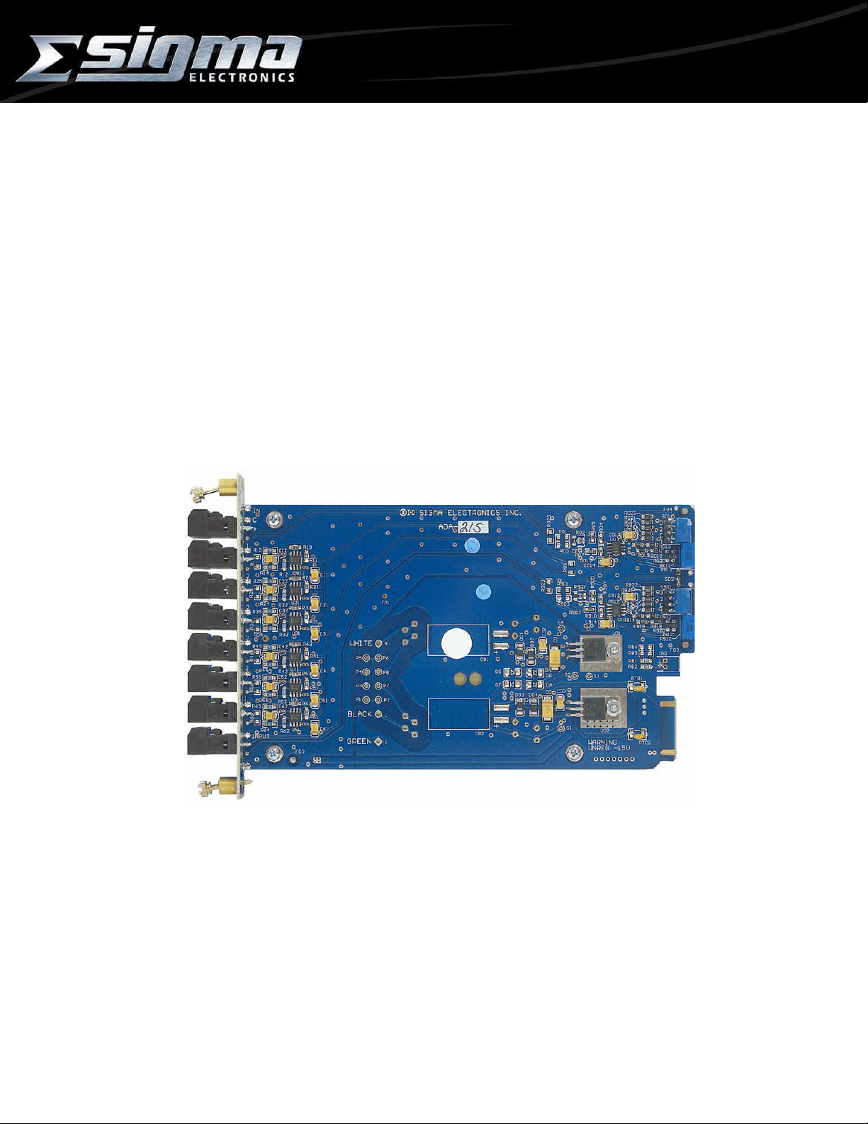
The ADA-21S Stereo Audio Distribution Amplifier is designed to provide three (3) dual-channel outputs
from a stereo audio s ignal sour c e. T he module is compatible with either balanced or unbalanced audio signals
on the input and outputs. Outputs can be mixed between balanced and unbalanced conf iguration dependent
on the requirement of the destination equipment.
This module m ust be installed in a Sigma Frame f or proper operation. Power is provided by the power
supply within the frame. A Sigma frame is designed to accomm odate any 2100 Series m odule. This allows the
ADA-21S to be resident with any other Sigma 2100 Series module in a common frame.
POWER:
The ADA-21S operates from bus voltages of unregulated +20Vdc and -20Vdc. These voltages are supplied
by the Sigma frame / power supply. The module regulates the bus voltage to +15Vdc and -15Vdc. Circuit
protection is provided by PTC Thermistors (Positive Temperature Coefficient Thermal Resistor) which serve
as a permanent fuse. Upon correction of the fault, the PTC Thermistor will reset.
FRAMES:
The ADA-21S m odule can reside in any of four different fr ames provided by Sigma Electronics, Inc. If this
module is purchased as a component of a system, please refer to the SERIES 2100 FRAMES Instruction
Manual. If the module was purchased separately, an existing frame must be present for proper operation.
Sigma would like to emphasize the fact that any of the Series 2100 modules can be mixed in any frame.
♦ The SS-2100-2 fram e is als o des igned f or desk top applications. This frame provides two (2) slots for dual
module configurations; i.e. stereo audio.
♦ The SS-2100-6 fram e is des igned for 19 inch EIA rac k installations. It pr ovides six (6) s lots f or m odules in
1 rack unit of space.
♦ The SS-2100-12+ f rame provides thirteen (13) slots f or modules within 3 RU. Redundant power supplies
are provided within this frame.
♦ The SS-2100-16+ frame is also available for installations in a 19 inch EIA rack. This frame provides
seventeen (17) slots for modules within 3 RU.
Additional inf ormation on the various f rames is available. Please r efer to the special section on f rames if
this was purchased as a com plete s ystem. If this information is not provided with this shipment, contact Sigma
Electronics for assistance.
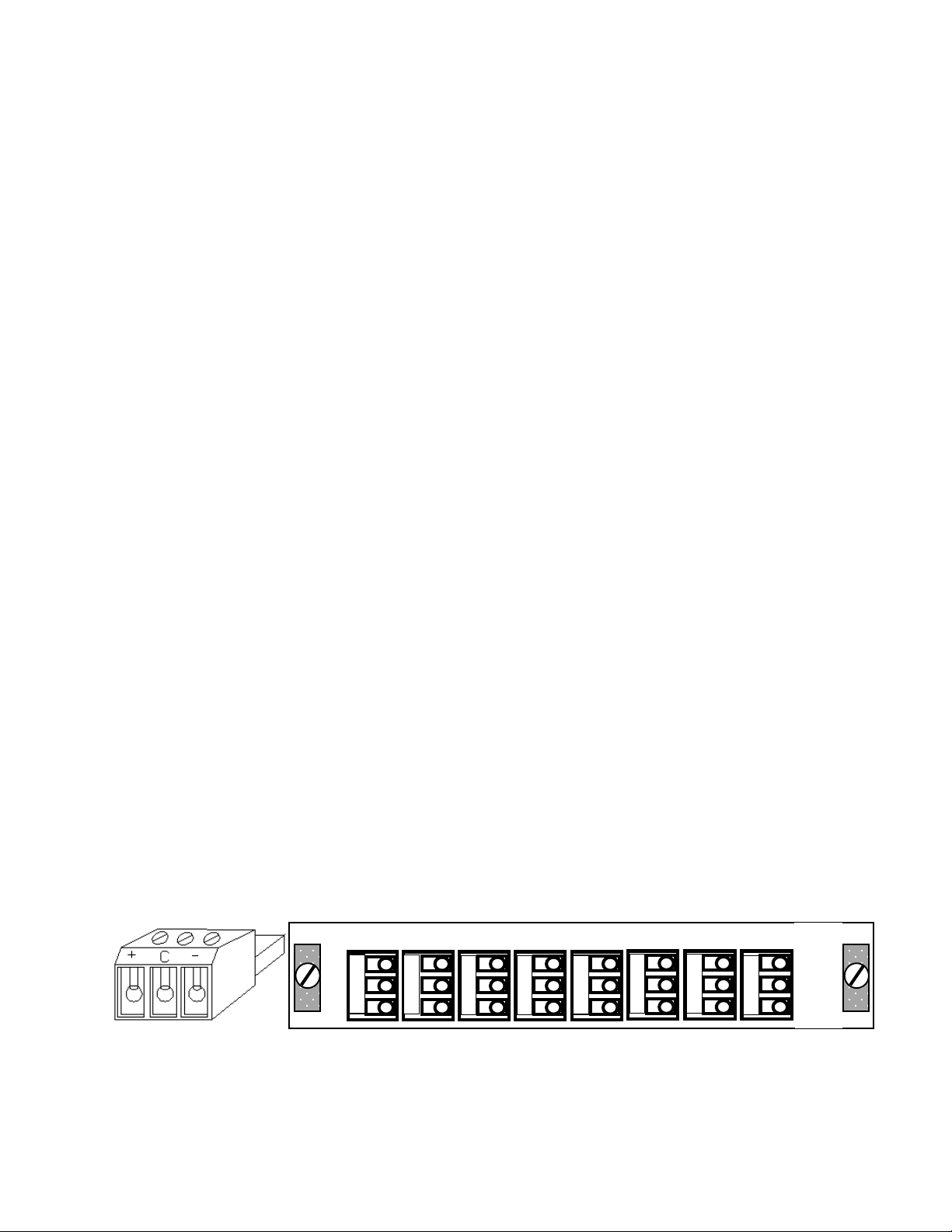
CONNECTIONS:
Wiring to the module is performed via detachable screw terminal connectors (Figure 1).
INPUT: There are dual-channel inputs on the rear panel of the unit; the firs t and last connectors (Figure
2). The Right channel is on the lef t (or top if mounted ver tically) and the Left channel is on the right as seen
from the rear of the unit. Both inputs are a high impedanc e configuration. T his allows the audio signals to be
bridged to other units. To ensure proper im pedance matching it may be necessary to terminate the outputs
with a 600Ω load. It is recommended that, if ter mination is necessary, use a 600Ω, 1/2 watt resistor across the
(+) and (-) outputs. W hen multiple units have inputs bridged to the sam e source, only apply the 600Ω resistor
to the last unit in the line.
OUTPUT: T here are three (3) outputs on the rear panel of the unit f or each channel . Each output is
designed to drive a 600Ω load. Since each output on a channel is identical, the numbering is only provided for
the operator’s convenience.
1
C
+
INPUT R
AUDIO CONNECTOR REAR PANEL CONNECTIONS
Figure 1 Figure 2
ADA-21 Doc. No. – 14466
2
C
+
C
+
3
C
+
3
C
+
2
C
+
1
C
+
C
+
INPUT L
ADA-21S
Page 1 of 3
Page 3

ADA-21S STEREO AUDIO DISTRIBUTION AMPLIFIER
p
AUDIO CONFIGURATIONS:
The source and destination audio equipment must be evaluated to determine if they are Balanced or
Unbalanced. After determination is made, refer to the drawings provided to select the proper audio
configuration. The outputs can be any combination of balanced or unbalanced.
+
C
-
ADA-21
+
C
-
+
C
-
+
C
-
+
C
-
IN OUT
Balanced In to Balanced Out Balanced In to Unbalanced Out
Vout = Vin Vout = 0.5 Vin
+
Gnd
ADA-21
+
C
-
+
C
-
+
C
-
+
Gnd
IN OUT
Unbalanced In to Balanced Out Unbalanced In to Unbalanced Out
(-) Input Grounded; Vout = Vin Vout = 0.5 Vin
(-) Input Floating: Vout = 0.75 Vin
ADA-21
+
C
-
+
C
-
IN OUT
ADA-21
+
C
-
+
C
-
IN OUT
+
C
Open
+
C
en
O
The input to output level comparison pr ovided in the figures above, assumes the outputs are terminated
into a 600Ω load.
FRONT PANEL:
The adjustments and indicator s on the f ront panel (Figure 3) c an be accessed through the s lots provided
in the fram e in which the ADA-21S is installed. W hen mounted within the SS-2100 Series fram es, it will be
necessary to remove the front panel of the frame to gain access to these items. Factory settings of the module
provide unity gain when terminated in 600Ω, and a bandwidth of 30 KHz.
Gain control for the right channel is achieved by adjustments to S01and R012. Gain control for the left
channel is achieved by adjustments to S901and R912. S01 and S901 provide gain adjustm ent in increments
of 6dB, while R012 and R912 provide fine adjustments of +/- 3dB. The positions of S01 make the following
adjustments to the gain level of the cir cuit - = O FF, 1= -6dB, 2= 0dB, 3= +6dB, 4= +12dB, 5= +18dBand 6=
+24dB.
R912
Figure 3: Front Panel Gain Adjustment
2
1
S901
3
4
5
6
R012
1
3
2
S01
4
5
6
ADA-21 Doc. No. – 14466
Page 2 of 3
Page 4

ADA-21S STEREO AUDIO DISTRIBUTION AMPLIFIER
ADJUSTMENTS:
The ADA-21S has no adjustments other than the front panel gain control.
SPECIFICATIONS:
INPUT: ...............................................Dual channel, Balanced, +24 dBm Maximum
INPUT IMPEDANCE: ........................30 kΩ Balanced, DC coupled
OUTPUT: ...........................................+24 dBm Maximum
OUTPUT IMPEDANCE: ....................100Ω Balanced, DC coupled
LEFT/RIGHT SEPARATION: ............All outputs driven into 600Ω, unused input terminated.
............................................................Greater than 80 dB, 20 Hz to 20 KHz
HUM and NOISE: ..............................less than -80 dBm at Unity Gain, 22Hz to 22Khz filter
less than -65 dBm at +27 dB Gain, 22Hz to 22Khz filter
THD+N: .............................................Into 600Ω, 22Hz to 22Khz filter, 0dBm to +24 dBm
less than 0.05% 20 Hz to 20KHz)
IND (SMPTE 4:1 60Hz/7KhZ): ..........same conditions as THD+N, less than 0.02%
GAIN RANGE: ...................................(-6) to +24 dB in 6dB steps,±3dB vernier when terminated into 600Ω.
GAIN VARIATION: ............................±0.3 dB
CMR: .................................................Greater than 70 dB at 60 Hz, 60 dB at 20 KHz
0dBm to +24dBm
RESPONSE: ......................................Into 600Ω, ±0.2 dB, 20 Hz to30 KHz
TECHNICAL MANUAL:
A manual including schematics, circuit description, parts list and setup guide is available upon request. This
information is intended for the service of the module. Modules should be serviced by Qualified Personnel only!
Sigma Electronics, Inc. recommends service to be performed by our Factory Service Center.
Information is intended to give a general performance and operation guideline of the product.
Sigma Electronics, Inc.; P.O.Box 448; 1027 Commercial Avenue; East Petersburg, PA 17520-0448
Main Office: Tel: (717) 569-2681 Fax: (717) 569-4056
REV1 JUN00 ADA-21S
All specifications, drawings, dimensions, weights and other details are subject to change without notification.
ADA-21 Doc. No. – 14466
Page 3 of 3
 Loading...