

Page 1
ADA-21
AUDIO
DISTRIBUTION AMPLIFIER
INSTRUCTION MANUAL
SIGMA ELECTRONICS, INC.
P.O. Box 448
1027 COMMERCIAL AVENUE
EAST PETERSBURG, PA 17520-0448
(717) 569-2681
Page 2
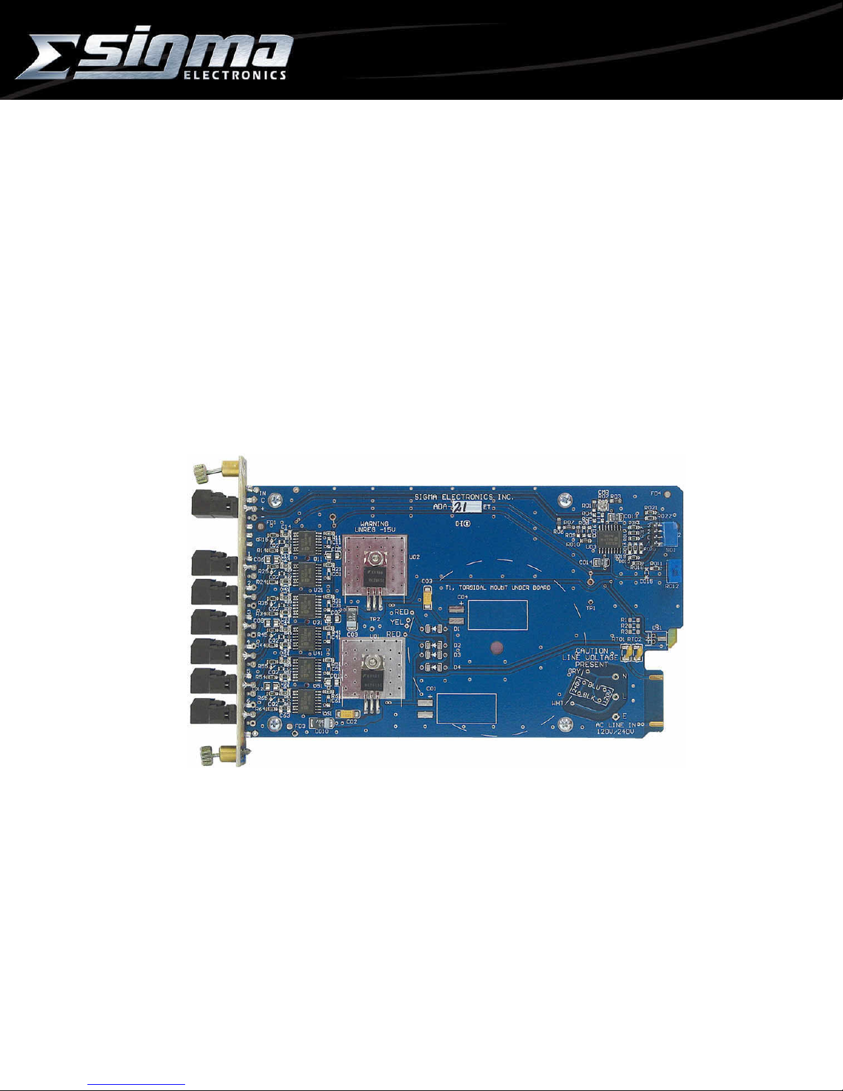
ADA-21 AUDIO DISTRIBUTION AMPLIFIER
GENERAL:
The ADA-21 Audio Distribution Amplif ier is designed to provide s ix (6) outputs from a single audio signal
source. The module is compatible with either balanced or unbalanced audio signals on the input and outputs.
Outputs can be mixed between balanced and unbalanced c onfiguration dependent on the requirement of the
destination equipment.
This module m ust be installed in a Sigma Frame for pr oper operation. Power is provided by the power
supply within the frame. A Sigma frame is designed to ac c ommodate any 2100 Series module. This allows the
ADA-21 to be resident with any other Sigma 2100 Series module in a common frame.
POWER:
The ADA-21 operates from bus voltages of unregulated +20Vdc and -20Vdc. These voltages are supplied
by the Sigma frame / power supply. The module regulates the bus voltage to +15Vdc and -15Vdc. Circuit
protection is provided by PTC Thermistors (Positive Temperature Coefficient Thermal Resistor) which serve
as a permanent fuse. Upon correction of the fault, the PTC Thermistor will reset.
FRAMES:
The ADA-21 module can reside in any of four different frames or Stand-Alone box provided by Sigma
Electronics, Inc. If this module is pur chased as a component of a system, please r efer to the SERIES 2100
FRAMES Instruction Manual. If the module was purchas ed separately, an existing frame m ust be present for
proper operation. Sigma would like to emphasize the fact that any of the Series 2100 modules can be mixed in
any frame.
♦ When assembled in a stand-alone box, it is assigned the model number ADA-26A. This is a desk top box.
♦ The SS-2100-2 frame is also designed for desk top applications. This f rame provides two (2) slots for dual
module configurations; i.e. stereo audio.
♦ The SS-2100-6 frame is designed f or 19 inch EIA r ack installations . It provides six (6) slots f or m odules in
1 rack unit of space.
♦ The SS-2100-12+ fram e provides twelve (13) slots for modules within 3 RU. Redundant power supplies
are provided within this frame.
♦ The SS-2100-16+ frame is also available for installations in a 19 inch EIA rack. This frame provides
sixteen (17) slots for modules within 3 RU.
Additional information on the various f rames is available. Please r efer to the special section on frames if
this was purchased as a com plete s ystem. If this information is not provided with this shipment, contact Sigma
Electronics for assistance.
CONNECTIONS:
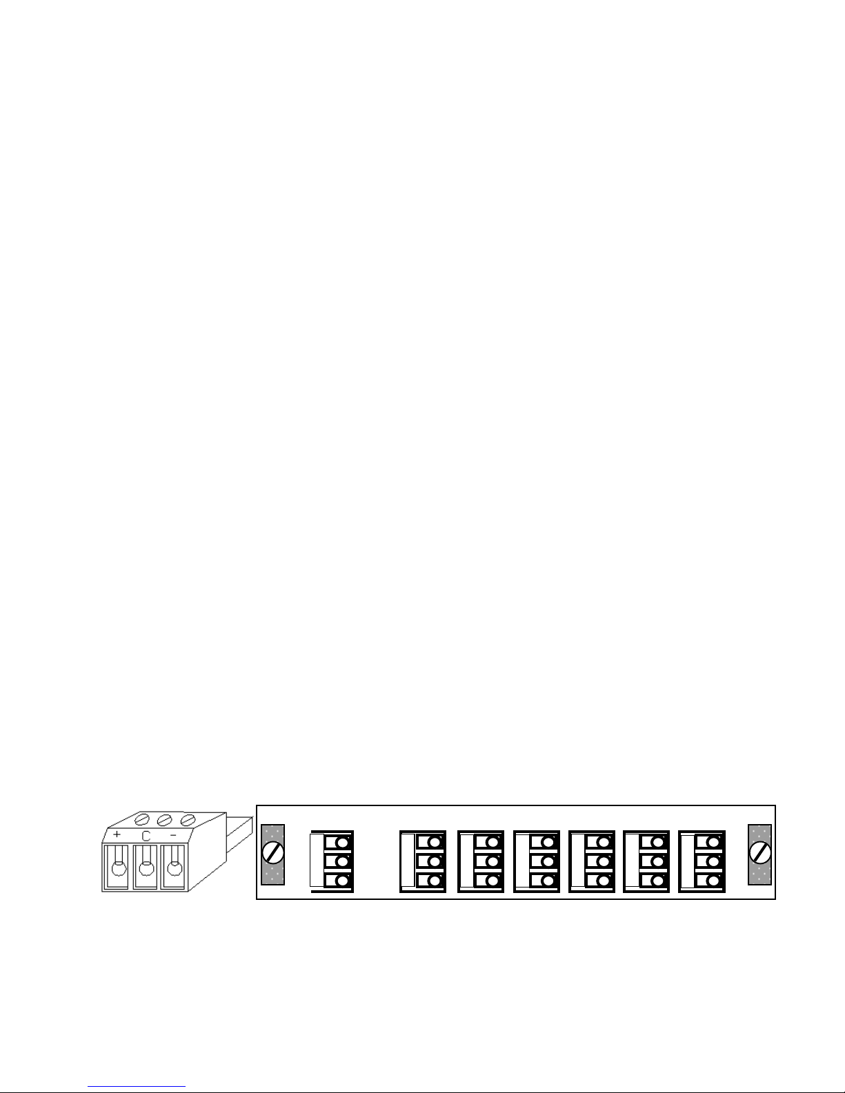
Wiring to the module is performed via detachable screw terminal connectors (Figure 1).
INPUT: There is a single input on the rear panel of the unit (Figure 2). The INPUT is a high impedance
configuration. This allows the audio signals to bridge to other units. To ensure proper im pedance matching it
may be necessary to terminate the outputs with a 600Ω load. It is recommended that, if termination is
necessary, use a 600Ω, 1/2 watt resistor across the (+) and (-) outputs. When multiple units have inputs
bridged to the same source, only apply the 600Ω resistor to the last unit in the line.
OUTPUT: Ther e are s ix ( 6) outputs on the r ear panel of the unit. Eac h output is des igned to drive a 600Ω
load.
1
C
INPUT
+
AUDIO CONNECTOR REAR PANEL CONNECTIONS
Figure 1 Figure 2
C
+
OUTPUT
ADA-21 Doc. No. – 13911
2 3
C
+
4
C
+
C
+
5 6
C
+
C
+
Page 1 of 3
ADA-21
Page 3

AUDIO CONFIGURATIONS:
The source and destination audio equipment must be evaluated to determine if they are Balanced or
Unbalanced. After determination is made, refer to the drawings provided to select the proper audio
configuration. The outputs can be any combination of balanced or unbalanced.
ADA-21
+
C
-
+
C
-
+
C
-
+
C
-
+
C
-
IN OUT
ADA-21
+
C
-
IN OUT
+
C
-
+
C
Open
Balanced In to Balanced Out Balanced In to Unbalanced Out
Vout = Vin Vout = 0.5 Vin
+
Gnd
ADA-21
+
C
-
IN OUT
+
C
-
+
C
+
Gnd
-
ADA-21
+
C
-
IN OUT
+
C
-
+
C
Open
Unbalanced In to Balanced Out Unbalanced In to Unbalanced Out
(-) Input Grounded; Vout = Vin Vout = 0.5 Vin
(-) Input Floating: Vout = 0.75 Vin
The input to output level comparison provided in the f igures above, assumes the outputs ar e terminated
into a 600Ω load.
FRONT PANEL:
The adjustments and indic ators on the front panel ( Figure 3) can be accessed thr ough the slots provided
in the frame in which the ADA-21 is installed. When mounted within the SS-2100 Series frames, it will be
necessary to remove the front panel of the frame to gain access to these items. Factory settings of the module
provide unity gain, maximum common mode rejection, and a bandwidth of 100 kHz.
Gain control is achieved by adjustments to S01and R102. S01 provides adjustment of the gain in
increments of 6dB, while R102 provides f ine adjus tm ents of +/- 3dB. T he positions of S01 m ak e the f ollowing
adjustments to the gain level of the circuit - = OFF, 1= -6dB, 2= 0dB, 3= +6dB, 4= +12dB, 5= +18dB and 6=
+24dB.
Figure 3: Front Panel Gain Adjustment
3
2
4
1
5
6
S01R102
ADA-21 Doc. No. – 13911
Page 2 of 3
Page 4

ADA-21 AUDIO DISTRIBUTION AMPLIFIER
ADJUSTMENTS:
Common Mode Rejection and Gain are both set for optimum performance by Sigma Electronics.
SPECIFICATIONS:
INPUT: ................................ Balanced, +24 dBm Maximum
INPUT IMPEDANCE: .......... 30 kΩ Balanced, 15 kΩ each line to ground
OUTPUT: ............................ +24 dBm Maximum
OUTPUT IMPEDANCE: ...... 150Ω Balanced
ISOLATION: ....................... 70 dB Minimum (15 kHz)
HUM and NOISE: ............... -90 dBm at Unity Gain
THD+N………………………. 0.005% 20 Hz to 20kHz (30kHz LPF)
GAIN RANGE: .................... -9 to +27 dB
CMR: .................................. 70 dB Minimum (20 Hz to 10 kHz)
60 dB Minimum (10 kHz to 20 kHz)
RESPONSE: ....................... +/- 0.2 dB Maximum to 100 kHz at Unity Gain
TECHNICAL MANUAL:
A manual including schematics, circuit description, parts list and setup guide is available upon request. This
information is intended for the service of the module. Modules should be serviced by Qualified Personnel only.
Sigma Electronics, Inc. recommends service to be performed by our Factory Service Center.
All specifications, drawings, dimensions, weights and other details are subject to change without notification.
Information is intended to give a general performance and operation guideline of the product.
Sigma Electronics, Inc.; P.O.Box 448; 1184 Enterprise Road; East Petersburg, PA 17520-0448
Main Office: Tel: (717) 569-2681 Fax: (717) 569-4056
REV1 OCT99 ADA-21
ADA-21 Doc. No. – 13911
Page 3 of 3
 Loading...