

SIGLENT SSG3000X User Manual

SSG3000X
Signal Generator
User Manual
UM0803X -E01A

SIGLENT
II SSG3000X User Manual
Guaranty and Declaration
Copyright
SIGLENT TECHNOLOGIES CO., LTD All Rights Reserved.
Trademark Information
SIGLENT is the registered trademark of SIGLENT TECHNOLOGIES CO., LTD
Declaration
SIGLENT products are protected by patent law worldwide
SIGLENT reserves the right to modify or change parts of or all the specifications or
pricing policies at company’s sole decision.
Information in this publication replaces all previously corresponding material.
Any way of copying, extracting or translating the contents of this manual is not allowed
without the permission of SIGLENT.
SIGLENT will not be responsible for losses caused by either incidental or consequential
in connection with the furnishing, use or performance of this manual as well as any
information contained.
Product Certification
SIGLENT guarantees this product conforms to the national and industrial standards in China
as well as the ISO9001: 2008 standard and the ISO14001: 2004 standard. Other international
standard conformance certification is in progress.

SIGLENT
SSG3000X User Manual III
General Safety Summary
Carefully read the following safety precautions to avoid any personal injury or damage to the
instrument and any products connected to it. To avoid potential hazards, please use the
instrument as specified.
Use Proper AC Power Line
Only the power cord designed for the instrument and authorized by local country should be
used.
Ground the Instrument
The instrument is grounded through the protective earth conductor of the power line. To avoid
electric shock, please make sure the instrument is grounded correctly before connecting its
input or output terminals.
Connect the Probe Correctly.
If a probe is used, do not connect the ground lead to high voltage since it has isobaric electric
potential as the ground.
Look Over All Terminals’ Ratings
To avoid fire or electric shock, please look over all ratings and sign instruction of the
instrument. Before connecting the instrument, please read the manual carefully to gain more
information about the ratings.
Use Proper Overvoltage Protection
Make sure that no overvoltage (such as that caused by a thunderstorm) can reach the product,
or else the operator might be exposed to danger of electrical shock.
Electrostatic Prevention
Operate the instrument in an electrostatic discharge protective area environment to avoid
damages induced by static discharge. Always ground both the internal and external
conductors of the cable to release static before connecting.
Maintain Proper Ventilation
Inadequate ventilation may cause increasing of the instrument’s temperature, which will
eventually damage the instrument. So keep well ventilated and inspect the intake and fan

SIGLENT
IV SSG3000X User Manual
regularly.
Avoid Exposed Circuit or Components
Do not touch exposed contacts or components when the power is on.
Do Not Operate Without Covers
Do not operate the instrument with covers or panels removed.
Use Only the Specified Fuse.
Keep Product Surfaces Clean and Dry.
To avoid the influence of dust and/or moisture in the air, please keep the surface of the device
clean and dry.
Do Not Operate in Wet Conditions.
In order to avoid short circuiting to the interior of the device or electric shock, please do not
operate the instrument in a humid environment.
Do Not Operate in an Explosive Atmosphere.
In order to avoid damage to the device or personal injury, it is important to operate the device
away from an explosive atmosphere.
SIGLENT
SSG3000X User Manual V
Safety Terms and Symbols
Terms used in this manual:
DANGER: Indicates an injury or hazard that may immediately happen.
WARNING: Indicates an injury or hazard that may not immediately happen.
CAUTION: Indicates that a potential damage to the instrument or other property might occur.
Symbols used on the instrument. Symbols may appear on the instrument:
Hazardous Protective Warning Chassis
Voltage Earth Ground Ground

SIGLENT
VI SSG3000X User Manual
SSG3000X Overview
The SIGLENT SSG3000X series is a bench top RF signal source, with an output frequency
range from 9 kHz to 3.2 GHz. It features light weight, small size, and convenient interface
make it ideal for R&D, education, production, and maintenance.
Features and Benefits
Frequency range from 9 kHz up to 3.2 GHz
0.01Hz frequency resolution
Level output from -110dBm~+20dBm.
0.01dBlevel resolution
Level accuracy ≤ 0.7dB(typ.)
Phase noise:<-110dBc/Hz @1GHz, offset 20kHz(typ.)
Standard AM, FM, and PM analog modulation with internal, external and Int+Ext
source
Pulse modulation, on/off ratio ≥0.7 dB (typ.)
Pulse train generator(option)
External IQ modulation with SDG6000X as the Baseband IQ signal
USB-power meter measurement
Equipped with a 5-inch (800x480) with display and a capacitive touch screen for
easy and convenient operation.

SIGLENT
SSG3000X User Manual VII
Contents
Guaranty and Declaration .......................................................................................................... II
General Safety Summary ......................................................................................................... III
Safety Terms and Symbols ........................................................................................................ V
SSG3000X Overview ................................................................................................................ VI
Chapter 1 Quick Start ........................................................................................................... 1
1.1 Appearance size .................................................................................................. 2
1.2 Preparing for Use ................................................................................................. 3
1.2.1 Adjust the Supporting Legs .......................................................................... 3
1.2.2 Connect to AC Power Supply ....................................................................... 3
1.3 The Front Panel ................................................................................................... 4
1.3.1 Front Panel Function Keys ........................................................................... 4
1.3.2 Front Panel Key Backlight ............................................................................ 5
1.3.3 Digital keyboard ............................................................................................ 6
1.3.4 Front Panel Connectors ................................................................................ 8
1.4 Rear Panel ........................................................................................................... 9
1.5 User interface ..................................................................................................... 13
1.6 Touch operation.................................................................................................. 15
1.7 Parameter setting ............................................................................................... 16
1.8 Help information ................................................................................................. 17
Chapter 2 Front Panel Operation........................................................................................ 18
2.1 Frequency Setting .............................................................................................. 19
2.1.1 RF output Frequency .................................................................................. 19
2.1.2 Freq Offset .................................................................................................. 20
2.1.3 Phase Offset ............................................................................................... 21
2.2 LevelSetting ....................................................................................................... 23
2.2.1 Level setting ................................................................................................ 23
2.2.2 Level Offset ................................................................................................. 24
2.2.3 ALC State .................................................................................................... 25
2.2.4 Flatness ...................................................................................................... 26

SIGLENT
VIII SSG3000X User Manual
2.3 SweepSetting ..................................................................................................... 29
2.3.1 Sweep State................................................................................................ 29
2.3.2 Step Sweep................................................................................................. 29
2.3.3 List sweep ................................................................................................... 30
2.3.4 Direction ...................................................................................................... 32
2.3.5 Sweep Mode ............................................................................................... 32
2.3.6 Trigger Mode ............................................................................................... 32
2.3.7 Point Trigger................................................................................................ 33
2.3.8 Trigger Slope .............................................................................................. 34
2.4 Modulation Setting ............................................................................................. 36
2.4.1 Amplitude Modulation (AM) ........................................................................ 36
2.4.2 Frequency Modulation (FM) ....................................................................... 39
2.4.3 Phase Modulation (PM) .............................................................................. 41
2.4.4 Pulse Modulation (PULSE) ......................................................................... 44
2.5 LF Setting ........................................................................................................... 54
2.5.1 LF Source ................................................................................................... 54
2.5.2 LF Sweep .................................................................................................... 55
2.6 Utility................................................................................................................... 58
2.6.1 System ........................................................................................................ 58
2.6.2 Store/Recall ................................................................................................ 65
2.7 Power Sensor..................................................................................................... 68
2.7.1 Power meter setting .................................................................................... 68
2.7.2 Level Control ............................................................................................... 72
2.8 I/Q Modulation .................................................................................................... 74
2.8.1 Turning on I/Q modulation .......................................................................... 74
2.8.2 I/Q source ................................................................................................... 74
2.9 Shortcut Keys ..................................................................................................... 75
2.9.1 Preset .......................................................................................................... 75
2.9.2 Home .......................................................................................................... 78
2.9.3 Trigger ......................................................................................................... 78

SIGLENT
SSG3000X User Manual IX
2.9.4 Esc/Close .................................................................................................... 78
2.9.5 Mod ON/OFF .............................................................................................. 79
2.9.6 RF ON/OFF................................................................................................. 79
Chapter 3 Application Examples......................................................................................... 80
3.1 Output RF signal ................................................................................................ 80
3.2 Output a modulated signal ................................................................................. 81
3.3 Output a pulse train ............................................................................................ 83
3.4 Output IQ modulated signal ............................................................................... 85
3.5 Test the OIP3 of Active Devices with the SSG3000X ........................................ 88
Chapter 4 Programming Overview ..................................................................................... 91
4.1 Remote Operation .............................................................................................. 91
4.1.1 Connecting via the USB Device port .......................................................... 91
4.1.2 Connecting via the LAN port ....................................................................... 92
4.1.3 GPIB: Connecting via the USB-Host port ................................................... 93
4.2 Build Communications ....................................................................................... 94
4.2.1 Build Communications Using VISA ............................................................ 94
4.2.2 Build Communications Using Sockets/Telnet ............................................. 96
4.3 Remote Control Capabilities .............................................................................. 97
4.3.1 User-defined Programming ........................................................................ 97
4.3.2 Send SCPI Commands via NI MAX ........................................................... 97
4.3.1 Web Control .............................................................................................. 100
Chapter 5 Service and Support ........................................................................................ 101
5.1 General Inspection ........................................................................................... 101
5.2 Troubleshooting ............................................................................................... 101
Chapter 6 Service and Support ........................................................................................ 105
6.1 Service Summary ............................................................................................. 105
6.2 Contact Us ....................................................................................................... 106


SIGLENT
SSG3000X User Manual 1
Chapter 1 Quick Start
Subjects in this chapter:
Appearance Appearance size
Preparing for Use
The Front Panel
Rear Panel
User interface
Touch operation
Parameter setting
Help information
SIGLENT
SSG3000X User Manual 2
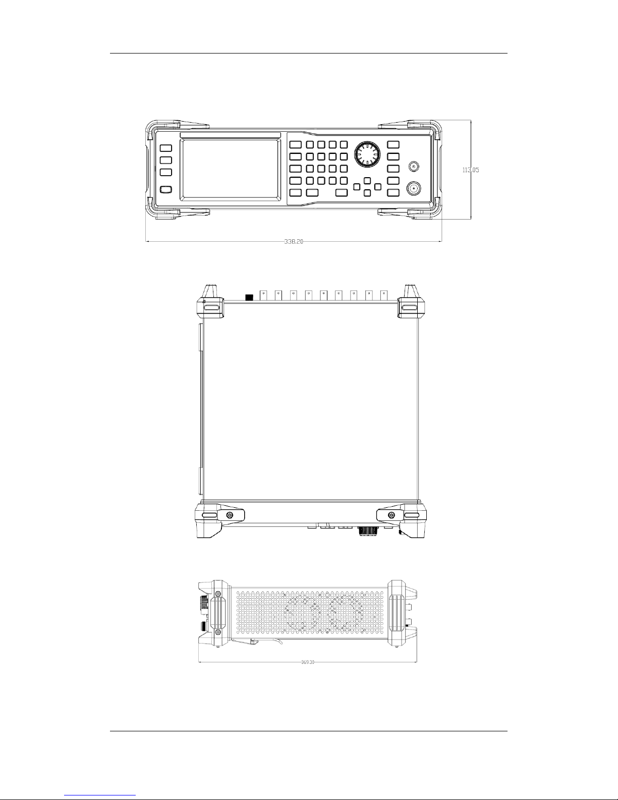
1.1 Appearance size
Figure 1-1 Front View
Figure 1-2 Top View
Figure 1-3 Side View
SIGLENT
SSG3000X User Manual 3
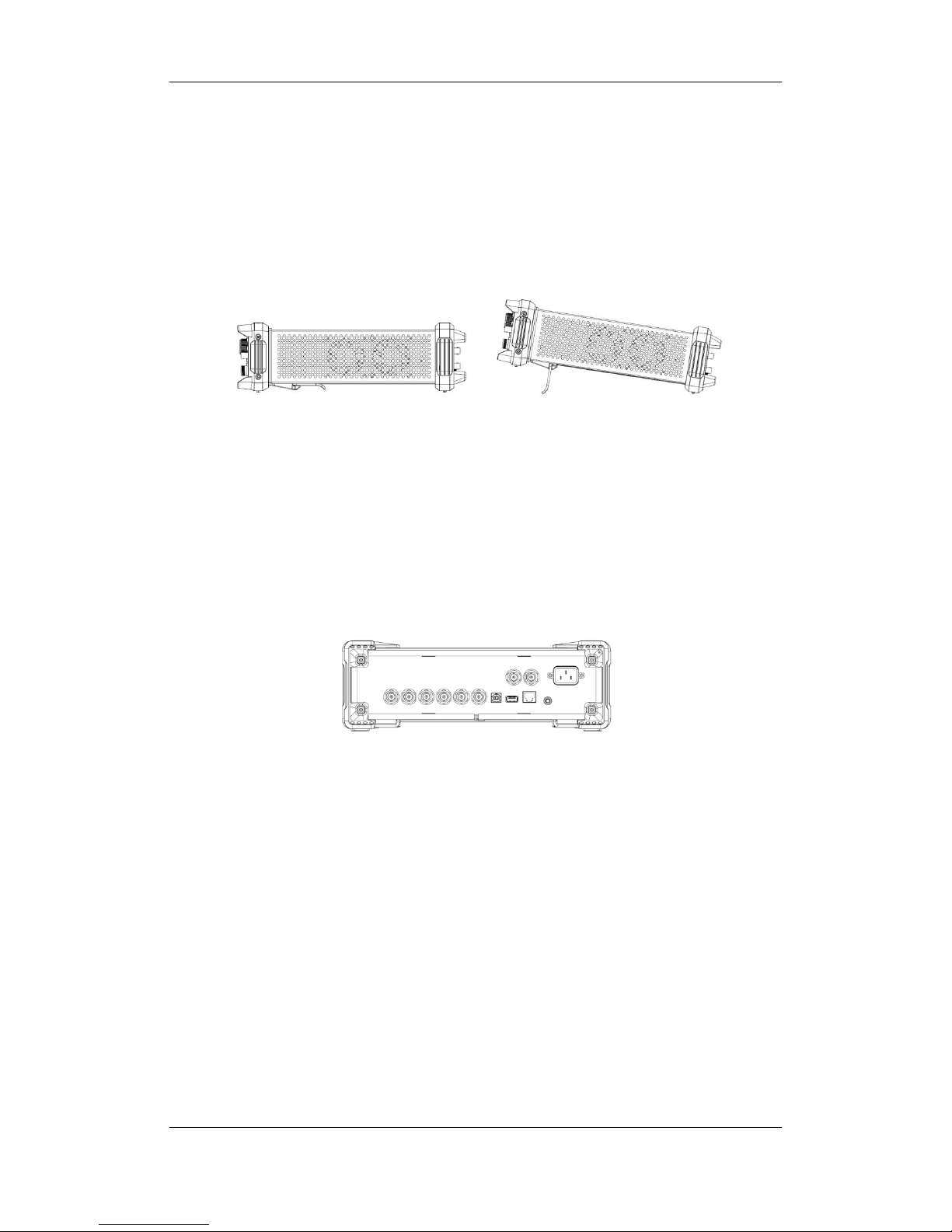
1.2 Preparing for Use
1.2.1 Adjust the Supporting Legs
For benchtop operation, you may want to use the supporting legs.Adjust the supporting
feet appropriately to tilt the RF signal source upwards.
Figure 1-4 before adjusting Figure 1-5 after adjusting
1.2.2 Connect to AC Power Supply
The RF signal source accepts 100-240V, 50/60/440Hz AC power supply. Please use the
power cord provided to connect the instrument to the power source as shown in the figure
below.
Figure 1-6 Power Interface
SIGLENT
SSG3000X User Manual 4
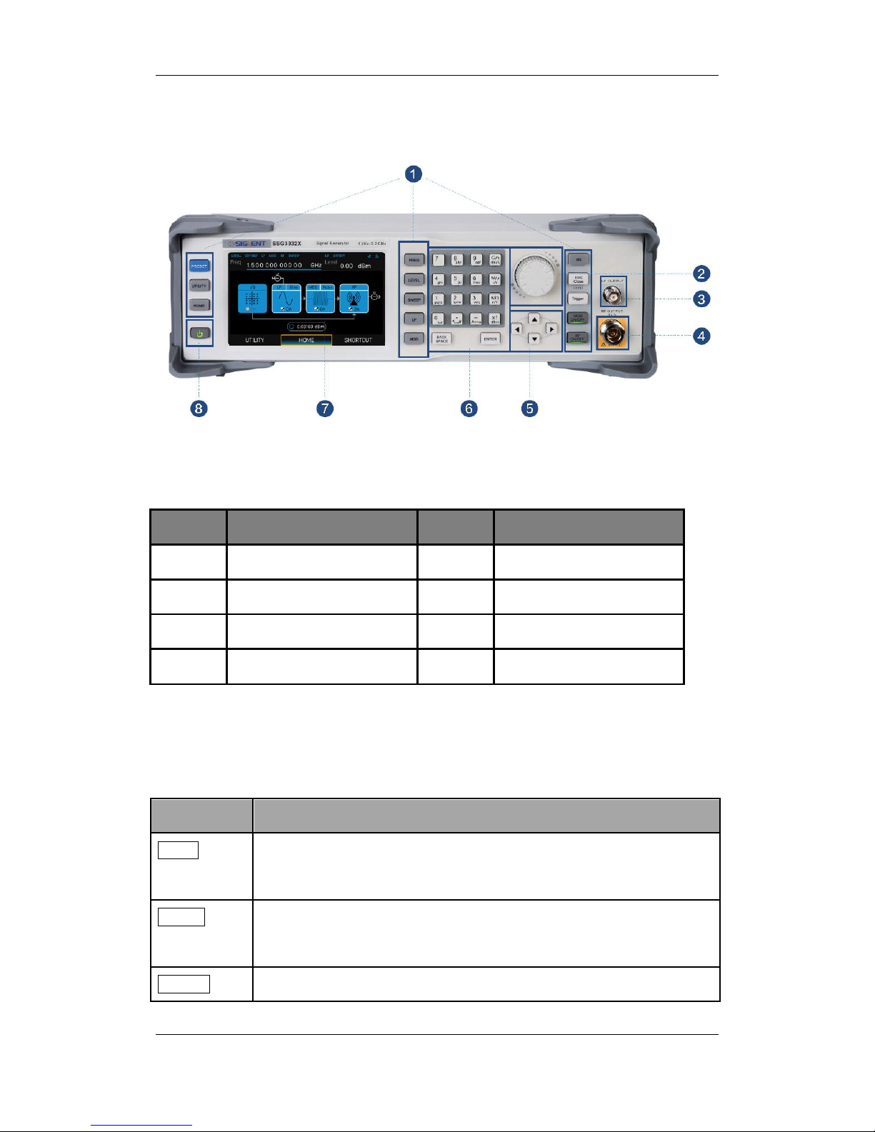
1.3 The Front Panel
Figure 1-7 the Front Panel
Table 1-1 Front Panel Description
NO.
Description
NO.
Description
1
Function key
2
Knob
3
LF output
4
RF output
5
Direction key
6
Digital keyboard
7
Touch screen display area
8
Power button
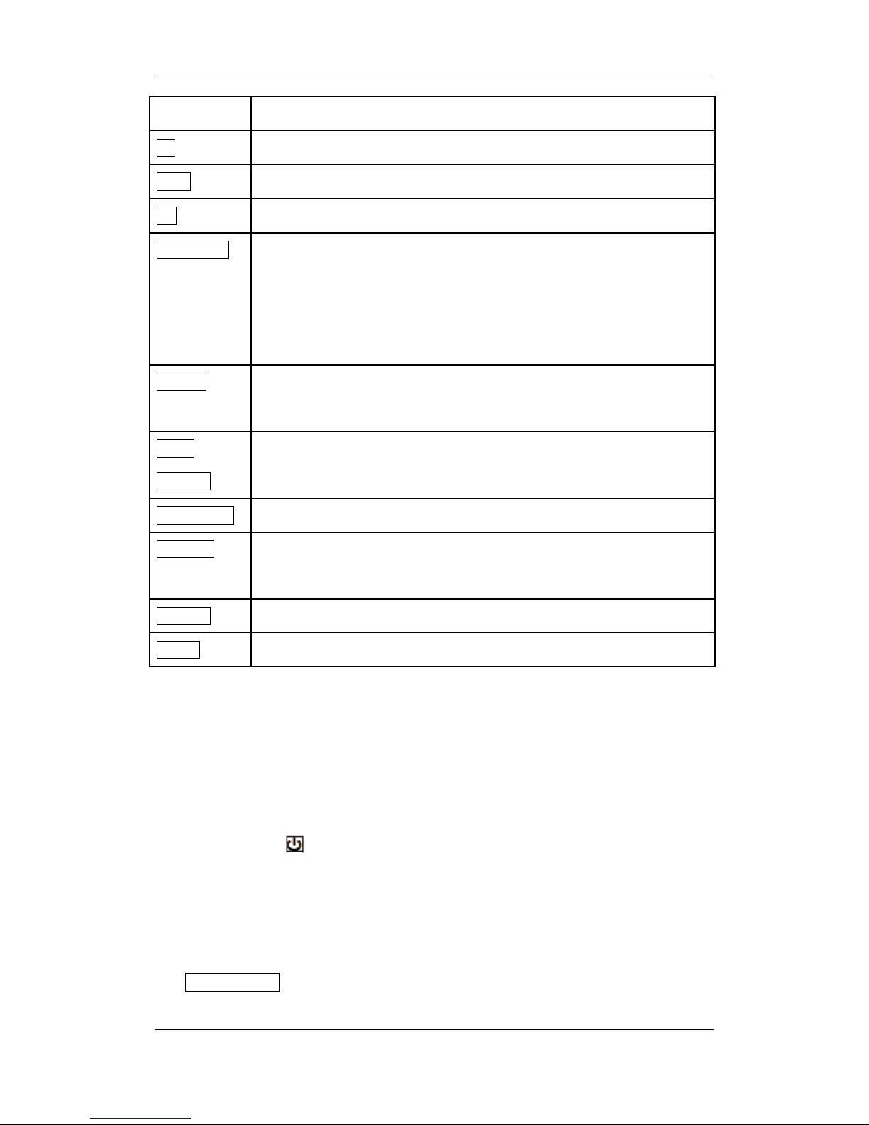
1.3.1 Front Panel Function Keys
Table 1-2 Function keys description
Control Keys
Description
FREQ
Set frequency, frequency offset, phase offset and other related
parameters.
LEVEL
Set level, level offset, ALC state, flatness and other parameters, power
sensor display and control functions.
SWEEP
Setsweep state, step sweep, list sweep, direction and other related
SIGLENT
SSG3000X User Manual 5
parameters.
LF
Set LF state, LF level, LF frequency and other related parameters.
MOD
Set various modulation parameters (AM, FM, PM and PULSE).
I/Q
Set IQ related parameters
ESC/Close
During the parameter or editing process, pressing this key will clear the
input of the active function area and exit the parameter input state.
Press this button to return to local control of previously operating the
instrument remotely.
Trigger
When the trigger type is set to Key, press this button to perform one
operation.
MOD
ON/OFF
The main switch of various modulation modes.
RF ON/OFF
RF signal output switch
PRESET
Press this button to revert to the default parameter. The default
parameters refer to the default parameter table.
UTILITY
System and file related operations
HOME
You can get back to the main interface quickly
1.3.2 Front Panel Key Backlight
The on/off state and the color of the backlights of some keys at the front panel indicate the
working state of the SSG. The states are as listed below.
1. Power Switch
Light on and off alternatively, in breathing state: indicate the unit is in stand-by state.
Constant on: indicate the instrument is in normal operating state.
2. Mode ON/OFF
When the Mode ON/OFF is set to turn on the modulation, the light will turn on, turn off the
SIGLENT
SSG3000X User Manual 6
modulation, and the lights will turn off.
3. RF ON/OFF
When the RF signal is turned on, the back light is on, and the radio signal is turned off.
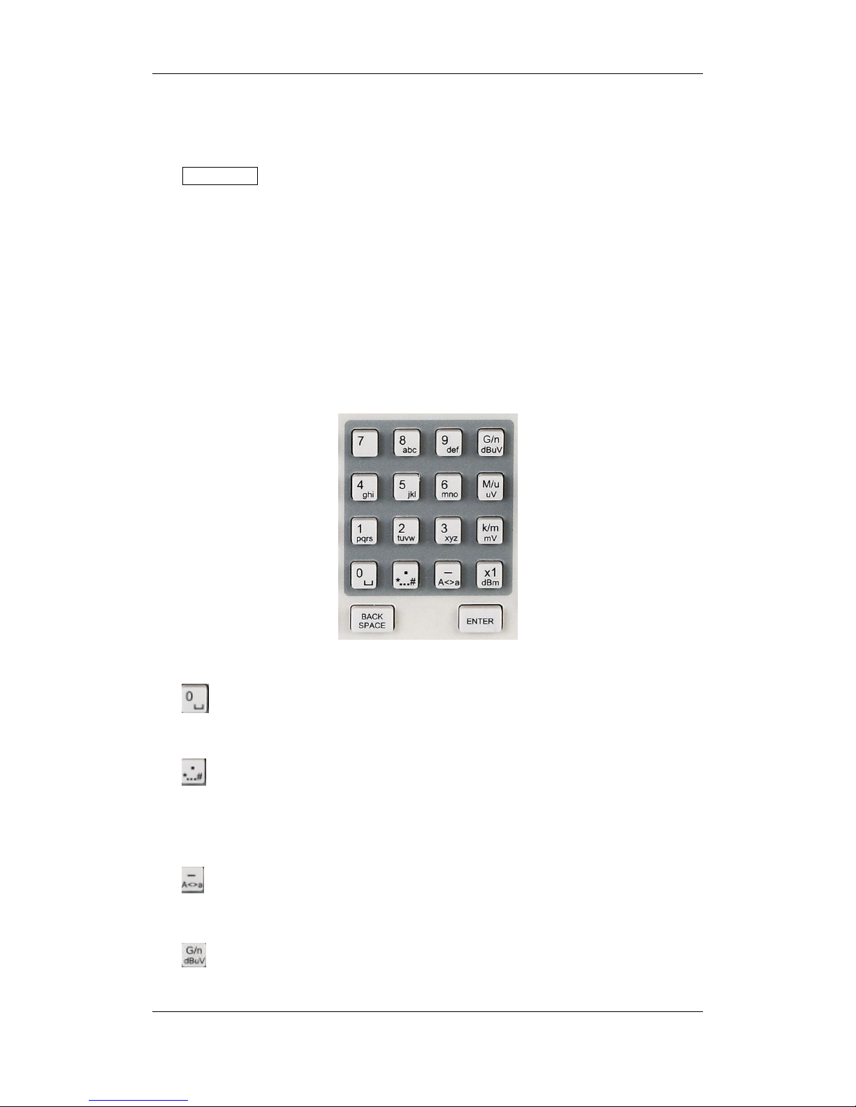
1.3.3 Digital keyboard
The front panel of the RF signal source provides a numeric keypad (as shown below). The
keyboard supports English uppercase and lowercase characters, numbers, and common
symbols (including decimal points, blanks, spaces, and + /), mainly for editing the name of
files or folders and setting parameters (refer to the "parameter setting" section).
Figure 1-8 Digital keyboard
1.
Digit 0 and space bar switch.
2.
In the English state, enter the special symbol!, @, #, $, %, ^, &, *) In the digital state, enter
the decimal point.
3.
In the digital state, enter the "-" number, in the English state input for case switching.
4.
When setting the amplitude, press this key to set the unitsas dBuV. When setting the
SIGLENT
SSG3000X User Manual 7
frequency, press this key to set the units as GHz, if the input is a time-related parameter,
press this key to set the unit tons.
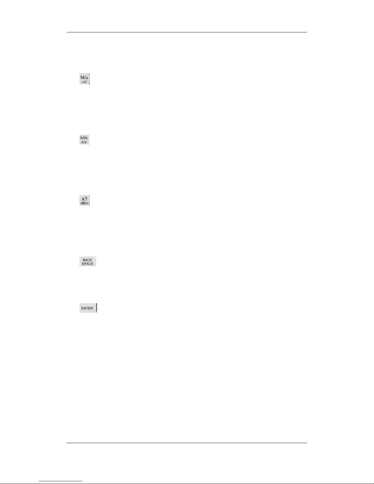
5.
When setting the amplitude, press this key to set the units as uV.When setting the
frequency, press this key to set the units as MHz, if the input is a time-related parameter,
press this key to set the unit to us.
6.
When setting the amplitude, press this key to set the units asmV. When setting
thefrequency, press this key to set kHz. If the input is a time-related parameters, press this
key to set the unitstoms.
7.
When setting the amplitude, press this key to set the units asdBm unit, whensetting a
frequency, the unit is Hz, if the input is a time correlation parameter, press this key to set
the units as s.
8.
During the parameter or editing process, pressing this key will clear the input of the active
function area and exit the parameter input state.
9.
In the parameter input process, pressing this key will end the parameter input and add the
currently set units for the parameter.
SIGLENT
SSG3000X User Manual 8
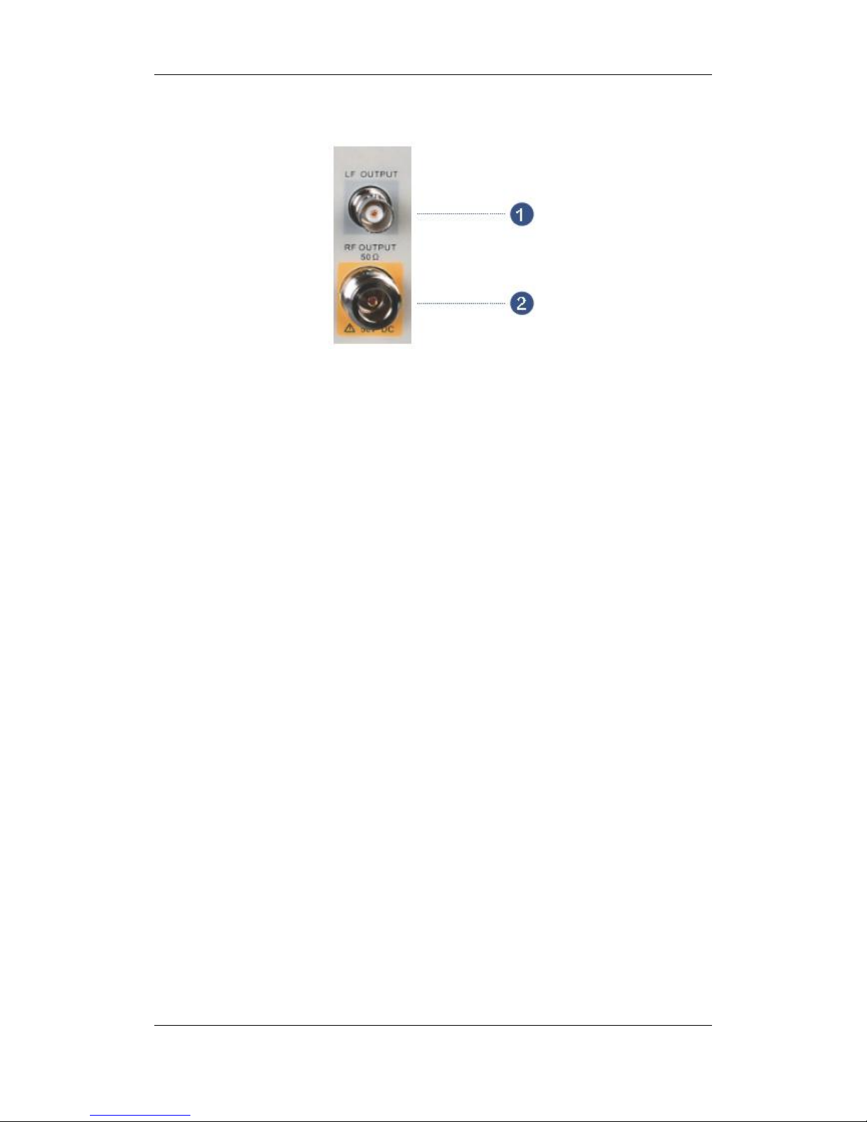
1.3.4 Front Panel Connectors
Figure 1-9 front panel connectors
1. LF (low frequency) output
Output the low frequency signal. This is a BNC connection .The output can also be
configured to source the modulation waveform for FM and PM modulation types.
2. RF(Radio frequency) output terminal
RF signal output N-type connector with an impedance of 50 ohms.
SIGLENT
SSG3000X User Manual 9
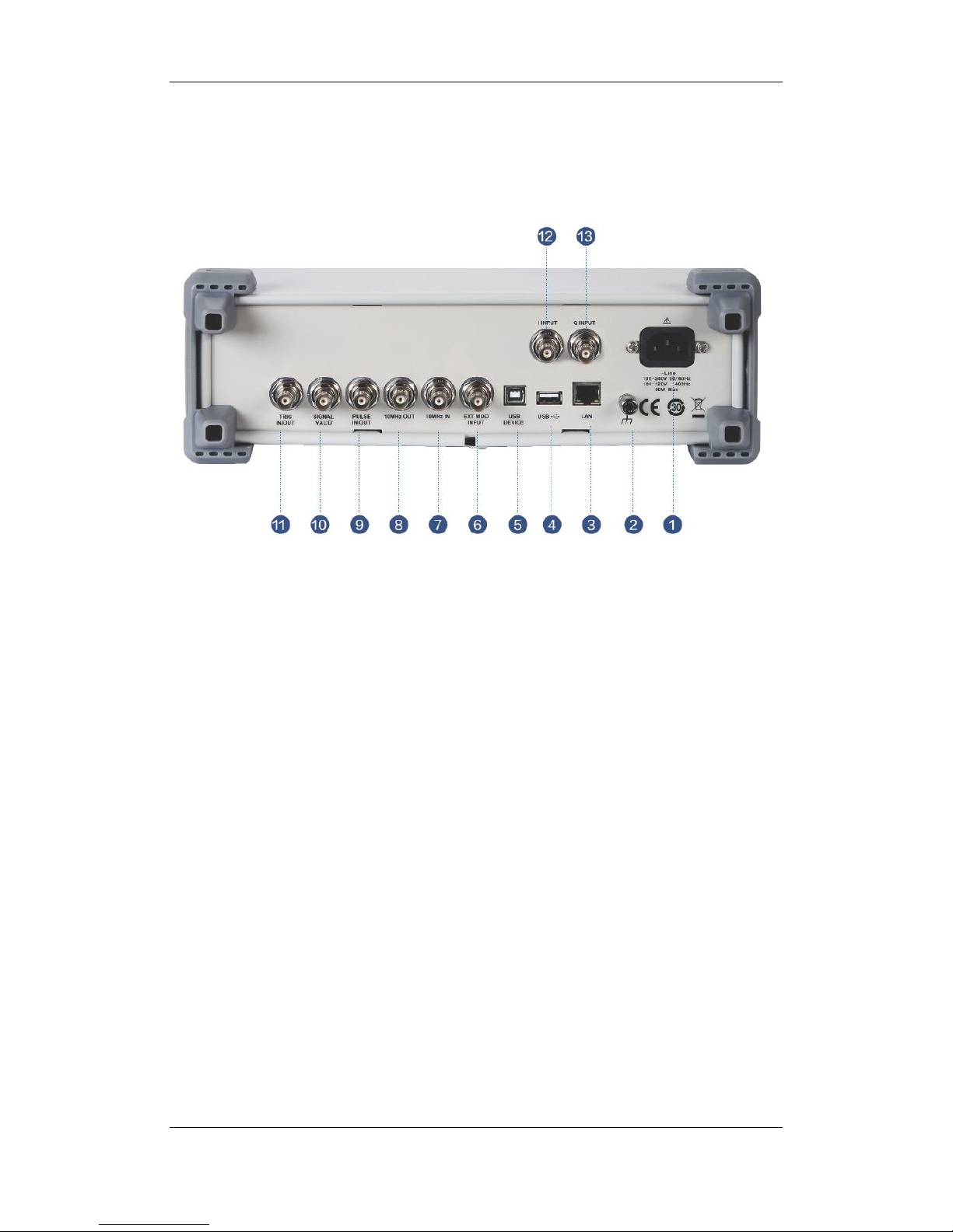
1.4 Rear Panel
Figure 1-10 Rear Panel
1. AC power input terminal
The RF signal source can operate with AC power from specifications of the AC power
supply supported by RF signal source are 100 V - 240 Vat 45 Hz - 440 Hz. Please connect
the RF signal source to the AC power supply with the supplied power cord.
2. Ground
System groundterminal.
3. LAN interface
Used to link the RF signal source to the computer or computer network, the SSG3000X is
VXI-11 compliant, supports remote commands based on Socket and Telnet, and uses
WEB for remote control. It can quickly build test systems with other standard equipment.
4. USB host

SIGLENT
SSG3000X User Manual 10
The RF signal source can be used as the "main device" to connect to the external USB
device. The interface reads the trace or state file from the U disk, or stores the current
instrument state or trace to the U disk, and can also save the content displayed on the
current screen in .BMP format to the U disk.
5. USB Device interface
The interface can be connected to a compatible computer and controlled by software on
the host computer
6. EXT MOD INPUT
Input BNC connection for an external modulation.
7. 10MHz IN
The [10MHz IN] and [10MHz OUT] connectors are commonly used to
establishsynchronization between multiple instruments.The RF source can use an internal
reference source or an external reference source.
If the instrument detects that there is a valid 10MHz IN signal at the 10MHz In connector, it
will used it as an external reference source. At this point the user interface status bar
shows "Ext Ref". When an external reference is lost, exceeded, or disconnected, the
instrument automatically switches to the internal reference, and the screen status bar will
no longer display "Ext Ref".
8. 10MHz OUT
The [10MHz IN] and [10MHz OUT] connectors are commonly used to
establishsynchronization between multiple instruments.The RF source can use an internal
reference source or an external reference source.

SIGLENT
SSG3000X User Manual 11
If the instrument uses an internal reference source, the [10MHz OUT] connector can
output a 10MHz clock signal generated by the instrument and can be used to synchronize
other devices.
9. PULSE IN/OUT
The function of the connector is determined by the current mode of pulse modulation.
1) PULSE IN:
When the pulse source is "Ext", it is used to input external pulse signals.
2) PULSE OUT:
When the Pulse modulation source is "Int" and the pulse output switch is turned on, it is
used to output the pulse signal generated by the internal generator. The output signal is
related to "Pulse Mode", and can be set to "Single", "Double" or "Train".
10. SIGNAL VALID
When the RF output frequency or amplitude is modified, the RF output connector of the
front panel outputs the RF signal at the specified frequency and amplitude after a certain
response and processing time in the internal circuit of the instrument. In this process, the
[SIGNAL VALID] connector outputs an impulse synchronization signal to indicate the
validity of the RF output signal:
High level (3.3 V): Indicates that the RF signal is being configured;
Low level (0 V): Indicates that the RF signal is stable (effective).
11. TRIG IN/OUT
When PULSE trigger mode is "Int ", the connector can be used to output the trigger signal.
When the RF Sweep, LF Sweep, or PULSE trigger mode is "Ext", the connector is used to
input the external trigger signal.
12. I INPUT

SIGLENT
SSG3000X User Manual 12
Used to input an external modulated I baseband signal when the external IQ modulation
mode is on.
13. Q INPUT
Used to input an external modulated Q baseband signal when the external IQ modulation
mode is on.
Note: [I INPUT] and [Q INPUT] connectors are only available on models equipped with IQ
modulation.
SIGLENT
SSG3000X User Manual 13
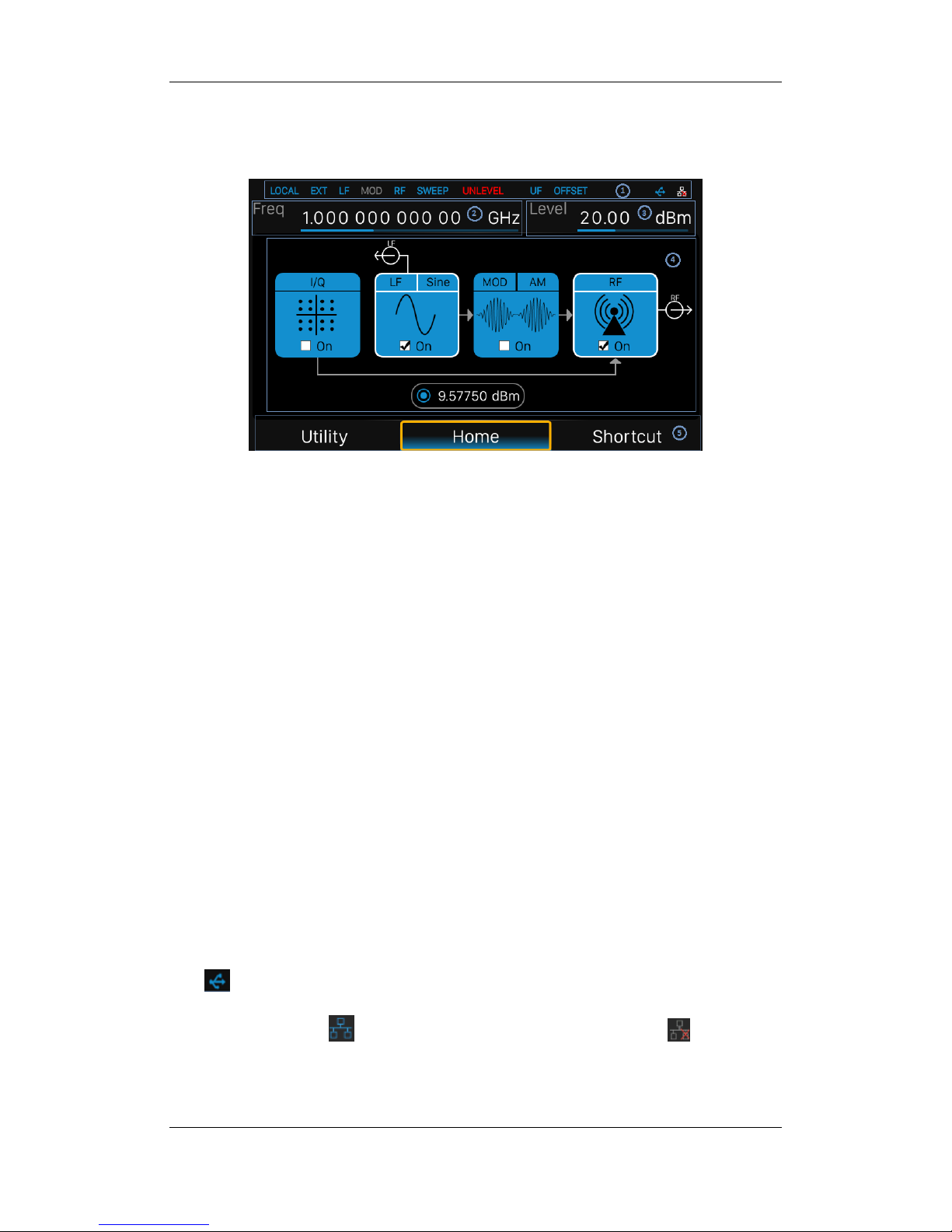
1.5 User interface
Figure 1-11 User Interface
1. Prompt status bar
Display Local (local), Remote (remote). When Remote is displayed, the instrument is
being controlled by a remote computer and the front panel input will be locked .To
unlock the front panel (enter Local mode).Esc/Close to quit.
Ext: Ext Ref shows that the SSG is using an external 10 MHz reference.
LF: Low frequency signal generator state.
MOD: The modulation state mode is turned off, the blue is turned on, and the gray is
closed.
RF: The RF output state.
SWEEP: The status of the sweep state.UNLEVEL: Indicates that the amplitude
accuracy may not be within the scope of the specification index.
UF: Amplitude flatness function enable.
OFFSET: Amplitude offset enable.
:The identification is displayed when a USB disk is inserted
LAN:LAN state. Indicates that LAN is successfully connected. indicates that
there is no network connection or network connection failed

SIGLENT
SSG3000X User Manual 14
2. RF frequency
RF output frequency setting. When the scan type is "frequency" or "frequency &
amplitude", the frequency scanning progress bar is displayed.
3. RF level
RF output level setting. When the scan type is "amplitude" or "frequency &litude", the
level scanning progress bar is displayed.
4. Touch screen display area: Display the settings under each menu
I/Q:I/Q output state
LF:LF output state and LF waveform displayed. Sine, Square, Sawtooth, Triangle
and DC can be set up.
MOD: Modulation state. Amplitude modulation, frequency modulation, phase
modulation, or pulse can be set.
RF:RF output state.
Power sensor:Display the current reading of the power sensor after accessing the
power sensor.
5. Menu
Switch menu and display menu after entering each function.

SIGLENT
SSG3000X User Manual 15
1.6 Touch operation
The RF signal source provides a 5 inch capacitive touch screen to support various gesture
operations. Including:
Click on the screen parameters or menu to edit the parameters.
Left or right slide switches menus.
Up and down slides the display menu
Note: Only when you click on the screen, the scrollbar appears on the right to slide down
the menu. If there is no scrollbar, it means that only the current page exists.
SIGLENT
SSG3000X User Manual 16
1.7 Parameter setting
Parameter input can be performed through touch screen, keypad and digital keys, knob or
direction keys. This section introduces an example of three parameter setting methods by
setting the center frequency to 100 MHz.
1. Using the digital keyboard
1) Press FREQ;
2) Use the numeric key to input the value "100";
3)Then press to select unit MHz;
2. Usingthe touch screen
1) Click the Freq input box on the screen to display the keypad.
2) Enter 100 on the keypad, then select unit MHz on the keypad.
3. Using the knob and the direction key
1) Bring the Focus Cursor on the Freq input box by using the knob.
2) Press the knob and adjust the left and right arrow keys to select the digit you wish
toadjust.
3) Then turn the knob or press the up and down arrow keys to change the parameters until
the desired value is obtained.
SIGLENT
SSG3000X User Manual 17
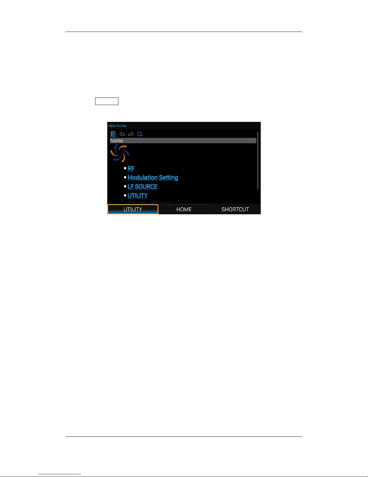
1.8 Help information
The built-in help system of RF signal source provides help information for each function
and menu option on the front panel.
Press UTILITYbutton and select help. The center of the screen will pop up to help.
Click to enter the corresponding directory.
Figure 1-12 help information

SIGLENT
SSG3000X User Manual 18
Chapter 2 Front Panel Operation
This chapter describes in detail the function keys at the front panel and the associated
functions.
Subjects in this chapter:
Frequency Setting
LevelSetting
Sweep Setting
Modulation Setting
LF Setting
Utility
Power Sensor
IQ modulation
Shortcut Keys
SIGLENT
SSG3000X User Manual 19
2.1 Frequency Setting
The value of the RF frequency is displayed in the header of the display (―Freq‖). This field
provides the direct input of the RF frequency. Alternatively, you can enter the RF
frequency in the ―Freq‖ dialog.
Note that the displayed RF frequency in the header and the RF output frequency, entered
in the ―FREQ‖ dialog can be different, as explained in the following section.
If you working with a downstream instrument, e.g. a mixer, you can enter related
parameter value in the frequency settings dialog (―Offset‖).
The correlation between the RF frequency, the RF output frequency and the frequency
offset is as follows:
―FREQ‖ (in header) = ―RF output frequency‖ (frequency in dialog) + ―Freq offset‖ (offset in
dialog)
2.1.1 RF output Frequency
Setting the RF output frequency
1. Keypad operation
Press FREQ->Frequency to make the focus fall on this parameter item.
Use the numeric keypad to input the desired value and press the unit button to select
the desired unit. Optional units are GHz, MHz, kHz, and Hz. Press ENTER to select
the current unit.
Press ENTER or press the knob to enter the parameter editing state, and then use
the left and right direction keys to move the cursor to the desired position. Press the
up and down direction keys, rotate the knob or press the numeric keypad to modify
the value. Press ENTER, knob or ESC to exit the editing mode.
SIGLENT
SSG3000X User Manual 20
2. Touch screen operation
Click on SHORTCUT->FREQ->Frequency to enter the interface of RF output frequency
setting.
Click the frequency parameter, then pop up the keypad interface, then click the
number symbol in the keypad to change the value. Click the unit to modify the unit.
Click the tick to confirm the modified value and selected unit.
Long press edit box to enter the edit mode. Press the up and down direction keys,
rotate the knob or press the numeric keypad to modify the value, and press the
ENTER key, knob or ESC key to exit the edit mode.
Note: The maximum RF output frequency is 3.2 GHz, and 9 kHz is the minimum.
2.1.2 Freq Offset
This setting the displayed frequency offset from the RF output signal.
This can be useful if the circuit or device shifts or alters the output frequency .such as an
external mixer, by setting an offset; you can read the mixer signal’s frequency directly on
the RF generator front panel.
1. Keypad operation
Press FREQ->Freq Offset to make the focus fall on this parameter item.
Use the numeric keypad to input the desired value and press the unit button to select
the desired unit. Optional units are GHz, MHz, kHz, and Hz. Press ENTER to select
the current unit.
Press ENTER or press the knob to enter the parameter editing state, and then use
the left and right direction keys to move the cursor to the desired position. Press the
up and down direction keys, rotate the knob or press the numeric keypad to modify
the value. Press ENTER, knob or ESC to exit the editing mode.
 Loading...