


SDS1000X-E Series
Digital Oscilloscope
User Manual
UM0101E-E03B

SDS1000X-E User Manual
Copyright and Declaration
Copyright
SIGLENT TECHNOLOGIES CO., LTD. All Rights Reserved.
Trademark Information
SIGLENT is the registered trademark of SIGLENT TECHNOLOGIES CO., LTD.
Declaration
SIGLENT products are protected by patent law in and outside of P.R.C.
SIGLENT reserves the right to modify or change parts of or all the specifications or pricing policies at company’s sole decision.
Information in this publication replaces all previously corresponding material.
Any way of copying, extracting or translating the contents of this manual is not allowed without the permission of SIGLENT.
Product Certification
SIGLENT guarantees this product conforms to the national and industrial stands in China and other international stands conformance certification is in progress.
Contact Us
If you have any problem or requirement when using our products, please contact SIGLENT TECHNOLOGIES CO., LTD
Add 3//F, Bldg No.4, Antongda Industrial Zone, 3rd Liuxian Road, Bao’an District, Shenzhen,
518101, P.R.China
Tel 400-878-0807 E-mail sales@siglent.com http://www.siglent.com
I
WWW.SIGLENT.COM

SDS1000X-E User Manual
Safety Information
General Safety Summary
Carefully read the following safety precautions to avoid any personal injury or damage to the instrument and any products connected to it. To avoid potential hazards, please use the instrument as specified.
Use Proper Power Line
Only the power cord designed for the instrument and authorized by local country could be used.
Ground the Instrument
The instrument is grounded through the protective earth conductor of the power line. To avoid electric shock, please make sure the instrument is grounded correctly before connecting its input or output terminals.
Connect the Signal Wire Correctly
The potential of the signal wire is equal to the earth, so do not connect the signal wire to a high voltage.
Look Over All Terminals’ Ratings
To avoid fire or electric shock, please look over all ratings and sign instruction of the instrument. Before connecting the instrument, please read the manual carefully to gain more information about the ratings.
Use Proper Overvoltage Protection
Make sure that no overvoltage (such as that caused by a thunderstorm) can reach the product, or else the operator might expose to danger of electrical shock.
Electrostatic Prevention
Operate in an electrostatic discharge protective area environment to avoid damages induced by static discharge. Always ground both the internal and external conductors of the cable to release static before connecting.
Keep Well Ventilation
Inadequate ventilation may cause increasing of temperature, which will eventually damage the instrument. So keep well ventilation and inspect the intake and fan regularly.
Avoid Circuit or Components Exposed
Do not touch exposed contacts or components when the power is on.
Use proper Fuse
Use only the specified fuse.
Do Not Operate Without Covers
Do not operate the instrument with covers or panels removed.
Do Not Operate With Suspected Failures.
If you suspect damage occurs to the instrument, have it inspected by qualified service personnel before further operations. Any maintenance, adjustment or replacement especially to circuits or accessories must be performed by SIGLENT authorized personnel.
II
WWW.SIGLENT.COM

SDS1000X-E User Manual
Do Not Operate in Wet Conditions.
In order to avoid short circuiting to the interior of the device or electric shock, please do not operate in a humid environment.
Do Not Operate in an Explosive Atmosphere.
In order to avoid damages to the device or personal injuries, it is important to operate the device away from an explosive atmosphere.
Keep Product Surfaces Clean and Dry.
To avoid the influence of dust and/or moisture in air, please keep the surface of device clean and dry.
Handling Safety
Please handle with care during transportation to avoid damages to buttons, knob interfaces and other parts on the panels.
Only probe assemblies which meet the manufacturer’s specifications shall be used.
When use 2X/…/10000X probe assemblies, the probe assemblies shall be insulated from the measured circuits by double or reinforced insulation.
All probe assemblies should meet the requirements of UL 61010-031 and CAN/CSA-C22.2 No. 61010-031-07.
Not to position the equipment so that it is difficult to operate the disconnecting device (detachable plug).
If the equipment is used in a manner not specified by the manufacturer, the protection provided by the equipment may be impaired
III
WWW.SIGLENT.COM

SDS1000X-E User Manual
Safety Terms and Symbols
Terms in this Manual. These terms may appear in this manual:
WARNING
Warning statements indicate the conditions or practices that could result in injury or loss of life.
CAUTION
Caution statements indicate the conditions or practices that could result in damage to this product or other property.
Terms on the product. These terms may appear on the product:
DANGER Indicates direct injuries or hazards that may happen. WARNING Indicates potential injuries or hazards that may happen.
CAUTION Indicates potential damages to the instrument or other property that may happen.
Symbols on the product. These symbols may appear on the product:
Hazardous |
protective Earth |
Warning |
Test |
Power Switch |
Voltage |
Terminal |
|
Ground |
|
If find such symbols on the product, consult the manual to find out the nature of the potential hazard and the actions which have to be taken
IV
WWW.SIGLENT.COM

SDS1000X-E User Manual
Measurement Category
Measurement Categories
This oscilloscope can make measurements in other circuits that are not directly connected to mains.
WARNING
This oscilloscope can only be used for measurements within its specified measurement categories.
Not to use the product for measurements within other measurement categories, such as CAT II, CAT III, CAT IV.
Not to use the equipment for measurements on mains circuits
Measurement Category Definitions
Measurement category II is for measurements performed on circuits directly connected to the low voltage installation. Examples are measurements on household appliances, portable tools and similar equipment.
Measurement category III is for measurements performed in the building installation. Examples are measurements on distribution boards, circuit-breakers, wiring, including cables, bus-bars, junction boxes, switches, socket-outlets in the fixed installation, and equipment for industrial use and some other equipment, for example. Stationary motors with permanent connection to the fixed installation.
Measurement category IV is for measurements performed at the source of the low-voltage installation. Examples are electricity meters and measurements on primary over current protection devices and ripple control units.
V
WWW.SIGLENT.COM
SDS1000X-E User Manual
Working Environment
Temperature
Operating: 10 to +40 Non-operation:-20 to +70 Humidity
Under +35 :≤90% relative humidity +35 to +40 : ≤60% relative humidity
WARNING
To avoid short circuit inside the instrument or electric shock, please do not operate in humid environment.
Altitude
Operating: less than 3 Km
Non-operation: less than 15 Km
Degree of protection
IP20
Installation (overvoltage) Category
This product is powered by mains conforming to installation (overvoltage) category II.
WARNING
Make sure that no overvoltage (such as that caused by thunderbolt) can reach the product, or else the operator might expose to danger of electric shock.
Installation (overvoltage) Category Definitions
Installation (overvoltage) category I refers to signal level which is applicable to equipment measurement terminals connected to the source circuit. In these terminals, precautions are done to limit the transient voltage to the corresponding low level.
Installation (overvoltage) category II refers to the local power distribution level which is applicable to equipment connected to the AC line (AC power).
Ventilation Requirement
This oscilloscope uses fan to force cooling. Please make sure that the air intake and exhaust areas are free from obstructions and have free air. When using the oscilloscope in a bench-top or rack setting, provide at least 10 cm clearance beside, above and behind the instrument for adequate ventilation.
WARNING
Inadequate ventilation may cause temperature increase which would damage the instrument. So please keep the instrument well ventilated during operation and inspect the intake and fan regularly.
VI
WWW.SIGLENT.COM

SDS1000X-E User Manual
General Care and Cleaning
Care
Do not store or leave the instrument in direct sunshine for long periods of time.
WARNING
To avoid damages to the instrument or probe, please do not leave them in fog, liquid, or solvent.
Cleaning
Please perform the following steps to clean the instrument and probe regularly according to its operating conditions.
1.Disconnect the instrument from all power sources, and then clean it with a soft wet cloth.
2.Clean the loose dust on the outside of the instrument and probe with a soft cloth. When cleaning the LCD, take care to avoid scarifying it.
WARNING
To avoid damages to the surface of the instrument and probe, please do not use any corrosive liquid or chemical cleanser.
WARNING
Make sure that the instrument is completely dry before restarting it to avoid short circuits or personal injuries.
VII
WWW.SIGLENT.COM

SDS1000X-E User Manual
L'information de sûreté
Résumé général de sûreté
Lisez soigneusement les mesures de sécurité suivantes pour éviter n'importe quelles blessures ou les dommages à l'instrument et à tous les produits se sont reliés à eux. Pour éviter des risques, utilisez svp l'instrument comme indiqué.
Employez la ligne à haute tension appropriée
Seulement le cordon de secteur conçu pour l'instrument et autorisé par le pays local a pu être employé.
A rectifié l'instrument.
L'instrument est fondu par le conducteur protecteur de terra de la ligne à haute tension. Pour éviter la décharge électrique, le conducteur moulu doit être relié à la terre. Assurez-vous que l'instrument est fondu correctement avant de relier ses bornes d'entrée ou de rendement.
Reliez le fil de signal correctement.
Le potentiel de l'au sol de fil de signal est égal à la terre, ainsi ne relie pas le fil de signal à une tension.
Regardez estimations au-dessus de toutes les bornes des'
Pour éviter le feu ou la décharge électrique, regardez svp au-dessus de toutes les estimations et instruction de signe de l'instrument. Avant de relier l'instrument, lisez svp le manuel soigneusement pour obtenir plus d'informations sur les estimations.
Employez la protection appropriée de surtension
Assurez-vous qu'aucune surtension (comme cela provoqué par un orage) ne peut atteindre le produit, ou bien l'opérateur pourrait exposer au danger du choc électrique.
Empêchement électrostatique
Fonctionnez dans un environnement protecteur de secteur de décharge électrostatique pour éviter des dommages induits par décharge statique. A toujours rectifié les conducteurs internes et externes du câble pour libérer la charge statique avant de se relier.
La ventilation insatisfaisante de ventilation
bonne de subsistance peut causer l'augmentation de la température, qui endommagera par la suite l'instrument. Gardez ainsi la ventilation bonne et inspectez la prise et éventez régulièrement.
Évitez le circuit ou les composants exposés
ne touchent pas les contacts ou les composants exposés quand le courant passe.
Employez l'utilisation appropriée de fusible seulement le fusible indiqué.
Ne fonctionnez pas sans couvertures
n'actionnent pas l'instrument des couvertures ou des panneaux étant coupés.
Ne fonctionnez pas avec des échecs suspectés.
Si vous suspectez les dommages se produisent à l'instrument, l'ont inspecté par le personnel de
VIII
WWW.SIGLENT.COM

SDS1000X-E User Manual
service qualifié avant d'autres opérations. N'importe quel entretien, ajustement ou remplacement particulièrement aux circuits ou aux accessoires doivent être exécutés par le personnel autorisé par SIGLENT.
Ne fonctionnez pas en conditions humides.
Afin d'éviter de court-circuiter à l'intérieur du dispositif ou de la décharge électrique, svp ne fonctionnez pas dans un environnement humide.
Do Not Operate in an Explosive Atmosphere.
Ne fonctionnez pas dans une atmosphère explosive.
Afin d'éviter d'endommager le dispositif ou les blessures, il est important d'utiliser le dispositif loin à partir d'une atmosphère explosive.
Maintenez les surfaces de produit propres et sèches.
Pour éviter l'influence de la poussière et/ou de l'humidité en air, maintenez svp la surface du dispositif propre et sèche.
En manipulant la sûreté
manipulez svp avec soin pendant le transport pour éviter d'endommager des boutons, des interfaces de bouton et d'autres parties sur les panneaux.
Sondez seulement les ensembles qui répondent aux caractéristiques du fabricant seront employés.
Quand des sondes de l'utilisation 5X/10X/50X/100X/500X/1000X, les sondes seront isolées des circuits mesurés par le double ou l'isolation renforcée.
Toutes les sondes devraient répondre aux exigences de l'UL 61010-031 et du CAN/CS A-C22.2 No. 61010-031-07
Le corps ou l'opérateur responsable devrait se référer au manuel d'instruction pour préserver la protection se permettent par l'équipement. Si l'équipement est utilisé en quelque sorte non indiqué par le fabricant, la protection fournie par l'équipement peut être altérée.
On ne permet à aucune pièce du dispositif et de ses accessoires d'être changé ou remplacé, autre qu'autorisé par le fabricant ou son agent.
Pas placez l'équipement de sorte qu'il soit difficile d'utiliser le dispositif débranchant (prise détachable).
IX
WWW.SIGLENT.COM
SDS1000X-E User Manual
Limites et symboles de sûreté
Limites en ce manuel. Ces limites peuvent apparaître en ce manuel :
Les rapports
d'avertissement D'AVERTISSEMENT indiquent les conditions ou les pratiques qui pourraient avoir
comme conséquence les dommages ou la perte de la ie.
Les rapports
d'attention d'ATTENTION indiquent les conditions ou les pratiques qui pourraient avoir comme consequence les dommages à ce produit ou à toute autre propriété.
Limites sur le produit. Ces limites peuvent apparaître sur le produit :
Le DANGER indique les dommages ou les risques directs qui peuvent se produire. Dommages ou risques potentiels de WARNINGIndicates qui peuvent se produire. L'ATTENTION indique des dommages potentiels à l'instrument ou à toute autre propriété qui peuvent se produire.
Si la trouvaille de tels symboles sur le produit, consultent le manuel pour découvrir la nature du risque et des actions qui doivent être pris.
Symboles sur le produit. Ces symboles peuvent apparaître sur le produit :
Dangereux |
Protecteur |
Avertissement |
Châssis |
Puissance |
Tension |
Au sol de la terre |
|
Ground |
Switch |
X
WWW.SIGLENT.COM

SDS1000X-E User Manual
Catégorie de mesure
Les oscilloscopes peuvent faire des mesures dans d'autres circuits qui ne sont pas directement reliés aux forces. Pour ne pas employer le produit pour des mesures dans d'autres catégories de mesure, telles que le CAT II, CAT III, CAT IV.
Ne pas utiliser l'équipement pour des mesures sur des forces circuite, pour ne pas utiliser l'équipement pour des mesures sur la tension excèdent la gamme de tension décrivent dans le manuel.
cet oscilloscope peut seulement être employé pour des mesures dans ses catégories indiquées de mesure.
La catégorie II de mesure
de définitions de catégorie de mesure est pour des mesures effectuées sur des circuits directement reliés à l'installation de basse tension. Les exemples sont des mesures sur des appareils électroménagers, des outils portatifs et l'équipement semblable.
La catégorie III de mesure est pour des mesures effectuées dans l'installation de bâtiment. Les exemples sont des mesures sur des conseils de distribution, des disjoncteurs, le câblage, y compris des câbles, des barres omnibus, des boîtes de jonction, des commutateurs, des douille-sorties dans l'installation fixe, et l'équipement à l'utilisation industrielle et à un autre équipement,
par exemple. Moteurs stationnaires avec le raccordement permanent à l'installation fixe.
La catégorie IV de mesure est pour des mesures effectuées à la source d'installation de basse tension.Les exemples sont des mètres et des mesures de l'électricité sur les dispositifs de protection d'excédent primaire et les unités de commande courants d'ondulation.
XI
WWW.SIGLENT.COM

SDS1000X-E User Manual
Environnement de fonctionnement
Opération
de la température : 10 au non-fonctionnement de +40 : - 20 à l'humidité
de +70
sous +35 : humidité relative +35
de ≤90% à +40 : humidité relative de ≤60%
EN AVERTISSANT
d'éviter le court-circuit à l'intérieur de l'instrument ou de la décharge électrique, svp ne fonctionnez pas dans l'environnement humide.
Opération
d'altitude : moins de 3 kilomètres
de non-fonctionnement : moins de 15 kilomètres
La catégorie d'installation (surtension)
ce produit est actionnée par des forces conformément à la catégorie II. d'installation (surtension).
EN AVERTISSANT
assurez-vous qu'aucune surtension (comme cela provoqué par coup de foudre) ne peut atteindre le produit, ou bien l'opérateur pourrait exposer au danger de la décharge électrique.
La catégorie II d'installation de définitions de catégorie d'installation
(surtension) (surtension) se rapporte au niveau local de distribution d'énergie qui est applicable à l'équipement relié à la ligne à C.A. (courant alternatif).
XII
WWW.SIGLENT.COM

SDS1000X-E User Manual
Condition de ventilation
This oscilloscope uses fan to force cooling. Please make sure that the air intake and exhaust areas are free from obstructions and have free air. When using the oscilloscope in a bench-top or rack setting, provide at least 10 cm clearance beside, above and behind the instrument for adequate ventilation.
Cet oscilloscope utilise le ventilateur pour forcer le refroidissement. Veuillez s'assurer que les secteurs d'entrée et d'échappement d'air sont exempts des obstructions et ont l'air libre. À l'aide de l'oscilloscope dans un mettre hors jeu-dessus ou un arrangement de support, fournissez au moins le dégagement de 10 centimètres près, au-dessus et derrière de l'instrument pour à ventilation proportionnée.
La ventilation insatisfaisante peut causer l'augmentation de la température qui endommagerait l'instrument. Veuillez ainsi la subsistance l'instrument bien aéré lors du fonctionnement et inspectez la prise et éventez régulièrement.
XIII
WWW.SIGLENT.COM

SDS1000X-E User Manual
Soin général et nettoyage
Ne stockez pas ou ne laissez pas l'instrument en soleil direct pendant de longues périodes.
Pour éviter d'endommager l'instrument, svp ne les laissez pas dans le brouillard, le liquide, ou le dissolvant.
nettoyage
Veuillez exécuter les étapes suivantes pour nettoyer l'instrument régulièrement selon ses conditions de fonctionnement.
1.Démontez l'instrument de toutes les sources d'énergie, et puis nettoyez-le avec un tissu humide mou.
2.Nettoyez la poussière lâche sur l'extérieur de l'instrument avec un tissu mou. En nettoyant l'affichage à cristaux liquides, salut pour éviter de le scarifier.
Pour éviter d'endommager la surface de l'instrument, svp n'utilisez aucune épierreuse corrosive de liquide ou de produit chimique.
Assurez-vous que l'instrument est complètement sec avant de le remettre en marche pour éviter des courts-circuits ou des blessures.
XIV
WWW.SIGLENT.COM

SDS1000X-E User Manual
Document Overview
This manual introduces how to use the digital oscilloscope in details.
Quick Start |
Provide information about preparations before |
|
using the instrument and a brief introduction of |
|
the instrument. |
Vertical System |
Introduce the functions of the vertical system of |
|
the oscilloscope. |
Horizontal System |
Introduce the functions of the horizontal system |
|
of the oscilloscope. |
Sample System |
Introduce the functions of the sample system of |
|
the oscilloscope. |
Trigger |
Introduce the trigger mode, trigger coupling, |
|
trigger hold off, external trigger and various |
|
trigger types of the oscilloscope. |
Serial Trigger and Decode |
Introduce the functions of the sample system of |
|
the oscilloscope. |
Reference Waveform |
Introduce how to save and display REF |
|
waveform. |
Math |
Introduce the math operation function of the |
|
oscilloscope. |
Cursors |
Introduce how to use cursors to make |
|
measurements. |
Measure |
Introduce how to use measure function to |
|
measure the waveform parameters. |
Display |
Introduce how to set the display of the |
|
oscilloscope. |
Save and Recall |
Introduce how to save and recall the |
|
measurement result and the setting of the |
|
oscilloscope. |
Digital Channels(Option) |
Introduce the oscilloscope's digital channel |
System Setting |
Introduce how to set the system setup. |
Bode Plot II |
Introduce how to set the Bode Plot II. |
Search |
Introduce the oscilloscope search function |
Navigate |
Introduce Describe how to use the waveform |
|
navigation function of the oscilloscope |
History |
Introduce how to use and set historical |
|
waveform functions. |
|
XV |
|
WWW.SIGLENT.COM |

SDS1000X-E User Manual |
|
Table of Content |
|
Copyright and Declaration ............................................................................................................. |
I |
Safety Information .......................................................................................................................... |
II |
General Safety Summary........................................................................................................... |
II |
Safety Terms and Symbols....................................................................................................... |
IV |
Measurement Category ........................................................................................................... |
V |
Working Environment ............................................................................................................. |
VI |
Ventilation Requirement......................................................................................................... |
VI |
General Care and Cleaning..................................................................................................... |
VII |
L'information de sûreté.............................................................................................................. |
VIII |
Résumé général de sûreté..................................................................................................... |
VIII |
Limites et symboles de sûreté................................................................................................... |
X |
Catégorie de mesure ................................................................................................................ |
XI |
Environnement de fonctionnement........................................................................................ |
XII |
Condition de ventilation......................................................................................................... |
XIII |
Soin général et nettoyage ..................................................................................................... |
XIV |
Document Overview.................................................................................................................... |
XV |
Quick Start....................................................................................................................................... |
1 |
General Inspection .................................................................................................................... |
2 |
Appearance and Dimensions .................................................................................................... |
3 |
Prepare for Using....................................................................................................................... |
5 |
Adjust the Supporting Legs........................................................................................... |
5 |
Connect the Power Supply ........................................................................................... |
5 |
Power-on Inspection ...................................................................................................... |
6 |
Connect the Probe ......................................................................................................... |
6 |
Function Inspection ........................................................................................................ |
6 |
Probe Compensation ..................................................................................................... |
8 |
Front Panel Overview................................................................................................................ |
9 |
Rear Panel Overview ............................................................................................................... |
11 |
Front Panel Function Overview............................................................................................... |
13 |
Horizontal....................................................................................................................... |
13 |
Vertical ........................................................................................................................... |
14 |
Trigger ............................................................................................................................ |
15 |
Run Control ................................................................................................................... |
16 |
Universal Knob.............................................................................................................. |
17 |
Menu............................................................................................................................... |
18 |
Help......................................................................................................................................... |
19 |
User Interface.......................................................................................................................... |
20 |
Security Lock ........................................................................................................................... |
23 |
Vertical System............................................................................................................................. |
24 |
Enable the Channel ................................................................................................................. |
25 |
Adjust Scale ............................................................................................................................. |
26 |
XVI |
|
|
WWW.SIGLENT.COM |

SDS1000X-E User Manual |
|
Vertical Position ...................................................................................................................... |
27 |
Coupling .................................................................................................................................. |
27 |
Bandwidth Limit ...................................................................................................................... |
28 |
Probe....................................................................................................................................... |
28 |
Input Impedance..................................................................................................................... |
29 |
Unit.......................................................................................................................................... |
29 |
Deskew .................................................................................................................................... |
29 |
Invert....................................................................................................................................... |
30 |
Trace Visible/Hidden............................................................................................................... |
30 |
Horizontal System ........................................................................................................................ |
30 |
Horizontal Scale....................................................................................................................... |
31 |
Trigger Delay............................................................................................................................ |
32 |
Roll Mode................................................................................................................................ |
33 |
Zoom Mode............................................................................................................................. |
34 |
Sample System............................................................................................................................. |
36 |
Run Control ............................................................................................................................. |
37 |
Overview ................................................................................................................................. |
38 |
Sampling Theory.............................................................................................................. |
38 |
Sample Rate .................................................................................................................... |
38 |
Bandwidth and Sample Rate ........................................................................................... |
39 |
Memory Depth........................................................................................................................ |
40 |
Sampling Mode ....................................................................................................................... |
41 |
Interpolation Method ............................................................................................................. |
41 |
Acquisition Mode .................................................................................................................... |
44 |
Normal ............................................................................................................................ |
44 |
Peak Detect ..................................................................................................................... |
45 |
Average............................................................................................................................ |
46 |
Eres.................................................................................................................................. |
47 |
Horizontal Format ................................................................................................................... |
49 |
Sequence Mode ...................................................................................................................... |
51 |
Trigger ............................................................................................................................................ |
53 |
Trigger Source ......................................................................................................................... |
55 |
Trigger Mode........................................................................................................................... |
56 |
Trigger Level ............................................................................................................................ |
58 |
Trigger Coupling ...................................................................................................................... |
59 |
Trigger Holdoff ........................................................................................................................ |
60 |
Noise Rejection ....................................................................................................................... |
61 |
Trigger Type............................................................................................................................. |
63 |
Edge Trigger.................................................................................................................. |
64 |
Slope Trigger................................................................................................................. |
65 |
Pulse Trigger ................................................................................................................. |
67 |
Video Trigger................................................................................................................. |
69 |
Window Trigger............................................................................................................. |
72 |
|
XVII |
|
WWW.SIGLENT.COM |

SDS1000X-E User Manual |
|
Interval Trigger .............................................................................................................. |
75 |
DropOut Trigger ............................................................................................................ |
77 |
Runt Trigger................................................................................................................... |
79 |
Pattern Trigger .............................................................................................................. |
81 |
Serial Trigger and Decode .......................................................................................................... |
83 |
I2C Trigger and Serial Decode ................................................................................................. |
84 |
Setup for I2C Signals ................................................................................................... |
84 |
I2C Trigger..................................................................................................................... |
85 |
I2C Serial Decode ........................................................................................................ |
89 |
SPI Trigger and Serial Decode.................................................................................................. |
90 |
Setup for SPI Signals................................................................................................... |
90 |
SPI Trigger..................................................................................................................... |
92 |
SPI Serial Decode ........................................................................................................ |
93 |
UART Trigger and Serial Decode.............................................................................................. |
94 |
Setup for UART Signals .............................................................................................. |
94 |
UART Trigger ................................................................................................................ |
96 |
UART Serial Decode.................................................................................................... |
97 |
CAN Trigger and Serial Decode ............................................................................................... |
98 |
Setup for CAN Signals................................................................................................. |
98 |
CAN Trigger................................................................................................................... |
99 |
CAN Serial Decode .................................................................................................... |
101 |
LIN Trigger and Serial Decode ............................................................................................... |
102 |
Setup for LIN Signals ................................................................................................. |
102 |
LIN Trigger................................................................................................................... |
103 |
LIN Serial Decode ...................................................................................................... |
105 |
Reference Waveform ................................................................................................................. |
107 |
Save REF Waveform to Internal Memory .............................................................................. |
108 |
Display REF Waveform .......................................................................................................... |
108 |
Adjust REF Waveform............................................................................................................ |
109 |
Clear REF Waveform.............................................................................................................. |
109 |
Math.............................................................................................................................................. |
111 |
Units for Math Waveforms.................................................................................................... |
112 |
Math Operators..................................................................................................................... |
113 |
Addition or Subtraction .............................................................................................. |
113 |
Multiplication and Division......................................................................................... |
114 |
FFT Operation............................................................................................................. |
115 |
Math Function Operation........................................................................................... |
120 |
Cursors......................................................................................................................................... |
125 |
X Cursors ............................................................................................................................... |
125 |
Y Cursors................................................................................................................................ |
125 |
Make Cursor Measurements................................................................................................. |
127 |
Measure ....................................................................................................................................... |
129 |
Type of Measurement ........................................................................................................... |
130 |
|
XVIII |
|
WWW.SIGLENT.COM |

SDS1000X-E User Manual |
|
Voltage Measurements ................................................................................................. |
130 |
Time Measurements ..................................................................................................... |
131 |
Delay Measurements .................................................................................................... |
132 |
Automatic Measurement ...................................................................................................... |
134 |
All Measurement................................................................................................................... |
136 |
Gate Measurement ............................................................................................................... |
137 |
Clear Measurement............................................................................................................... |
137 |
Display ......................................................................................................................................... |
138 |
Display Type .......................................................................................................................... |
139 |
Color Display ......................................................................................................................... |
140 |
Persistence ............................................................................................................................ |
141 |
Clear Display.......................................................................................................................... |
142 |
Grid Type ............................................................................................................................... |
142 |
Intensity ................................................................................................................................ |
142 |
Grid Brightness...................................................................................................................... |
143 |
Transparence......................................................................................................................... |
143 |
Save and Recall ......................................................................................................................... |
144 |
Save Type............................................................................................................................... |
145 |
Internal Save and Recall ........................................................................................................ |
147 |
External save and recall......................................................................................................... |
148 |
Disk Management ................................................................................................................. |
151 |
Create a New File or Folder...................................................................................... |
152 |
Delete a File or Folder ............................................................................................... |
153 |
Rename a File or Folder............................................................................................ |
153 |
Digital Channels(Option) ........................................................................................................... |
154 |
Connect the Digital Probes.................................................................................................... |
155 |
Acquire Digital Waveform ..................................................................................................... |
156 |
Digital Channels Height ......................................................................................................... |
156 |
Digital Channels Position....................................................................................................... |
157 |
Single Digital Channel............................................................................................................ |
157 |
All Digital Channels................................................................................................................ |
158 |
Logic Threshold ..................................................................................................................... |
158 |
Digital Bus.............................................................................................................................. |
159 |
Deskew .................................................................................................................................. |
160 |
System Setting....................................................................................................................... |
161 |
Remove Device...................................................................................................................... |
162 |
System Setting............................................................................................................................ |
163 |
View System Status............................................................................................................... |
164 |
Do Self Cal ............................................................................................................................. |
164 |
Quick-Cal ............................................................................................................................... |
166 |
Sound .................................................................................................................................... |
166 |
Language ............................................................................................................................... |
166 |
Pass/Fail Test ......................................................................................................................... |
167 |
|
XIX |
|
WWW.SIGLENT.COM |
SDS1000X-E User Manual |
|
Set and Perform Pass/Fail Test................................................................................ |
167 |
Save and Recall Test Mask....................................................................................... |
168 |
Arbitrary Waveform Generator(Option)................................................................................ |
171 |
Output........................................................................................................................... |
172 |
Wave............................................................................................................................. |
172 |
Setting .......................................................................................................................... |
174 |
Systems ....................................................................................................................... |
175 |
Remove Device .......................................................................................................... |
177 |
IO Set..................................................................................................................................... |
178 |
USB Device ................................................................................................................. |
178 |
LAN............................................................................................................................... |
178 |
WLAN ........................................................................................................................... |
179 |
Web Server............................................................................................................................ |
181 |
Update Firmware and Configuration..................................................................................... |
182 |
Do Self-Test............................................................................................................................ |
183 |
Screen Test.................................................................................................................. |
183 |
Keyboard Test ............................................................................................................. |
184 |
LED Test ...................................................................................................................... |
184 |
Screen Saver.......................................................................................................................... |
186 |
Reference Position ................................................................................................................ |
187 |
Power On Line ....................................................................................................................... |
187 |
Option Management............................................................................................................. |
188 |
Bode Plot II.................................................................................................................................. |
190 |
Perform Bode Plot................................................................................................................. |
190 |
Setting ................................................................................................................................... |
190 |
Example................................................................................................................................. |
194 |
Simple Sweep Operation........................................................................................... |
194 |
Vari-level Sweep Operation ...................................................................................... |
196 |
Search.......................................................................................................................................... |
199 |
Setting ................................................................................................................................... |
199 |
Results ................................................................................................................................... |
200 |
Navigate....................................................................................................................................... |
202 |
Time Navigate ....................................................................................................................... |
202 |
History Frame Navigate......................................................................................................... |
202 |
Search Event Navigate........................................................................................................... |
202 |
History........................................................................................................................................... |
204 |
Factory Setup ................................................................................................................................ |
206 |
Troubleshooting ............................................................................................................................ |
207 |
XX
WWW.SIGLENT.COM

SDS1000X-E User Manual |
|
Content of Figure |
|
Figure 1 Front View (2-channel scope) ..................................................................................... |
3 |
Figure 2 Top View (2-channel scope)........................................................................................ |
3 |
Figure 3 Front View (4-channel scope) ..................................................................................... |
4 |
Figure 4 Top View (4-channel scope)........................................................................................ |
4 |
Figure 5 Adjust the Supporting Legs ......................................................................................... |
5 |
Figure 6 To Connect to Power Supply ....................................................................................... |
6 |
Figure 7 Function Inspection..................................................................................................... |
7 |
Figure 8 2-channel Scope Front Panel Overview....................................................................... |
9 |
Figure 9 4-Channel Scope Front Panel Overview .................................................................... |
10 |
Figure 11 4-channel Scope Rear panel Overview.................................................................... |
12 |
Figure 12 Help Message.......................................................................................................... |
20 |
Figure 13 User Interface.......................................................................................................... |
20 |
Figure 14 To Use The Security Lock......................................................................................... |
23 |
Figure 16 Display Type Set to Dots.......................................................................................... |
42 |
Figure 17 x Interpolation......................................................................................................... |
43 |
Figure 18 Sinx/x Interpolation................................................................................................. |
43 |
Figure 19 Acquisition System .................................................................................................. |
44 |
Figure 20 Pulse With 0.1% Duty, Normal Mode ..................................................................... |
45 |
Figure 21 Pulse With 0.1% Duty, Peak Detect Mode .............................................................. |
46 |
Figure 22 With Random Noise, Normal Mode........................................................................ |
47 |
Figure 23 With Random Noise, Average Mode....................................................................... |
47 |
Figure 24 SEQUENCE Function Menu ..................................................................................... |
51 |
Figure 25 HISTORY Function Menu......................................................................................... |
51 |
Figure 26 Turn off the Noise Reject......................................................................................... |
61 |
Figure 27 Turn on the Noise Reject......................................................................................... |
62 |
Figure 28 Edge Trigger............................................................................................................. |
64 |
Figure 29 Slope Trigger............................................................................................................ |
66 |
Figure 30 Pulse Trigger............................................................................................................ |
68 |
Figure 31 Video Trigger........................................................................................................... |
71 |
Figure 32 Absolute Window Trigger........................................................................................ |
73 |
Figure 33 Relative Window Trigger......................................................................................... |
74 |
Figure 34 Interval Trigger ........................................................................................................ |
76 |
Figure 35 Edge DropOut Trigger.............................................................................................. |
78 |
Figure 36 State DropOut Trigger ............................................................................................. |
78 |
Figure 37 Runt Trigger............................................................................................................. |
80 |
Figure 38 Pattern Trigger......................................................................................................... |
82 |
Figure 39 I2C DECODE Menu................................................................................................... |
84 |
Figure 40 I2C SIGNALLE Menu ................................................................................................ |
84 |
Figure 42 SINGAL Menu .......................................................................................................... |
90 |
Figure 43 CLK Menu ................................................................................................................ |
90 |
XXI |
|
|
WWW.SIGLENT.COM |

SDS1000X-E User Manual |
|
Figure 44 MISO Menu ............................................................................................................. |
91 |
Figure 45 MOSI Menu ............................................................................................................. |
91 |
Figure 46 SPI TRIG SET Menu .................................................................................................. |
92 |
Figure 48 BUS CONFIG Menu.................................................................................................. |
94 |
Figure 50 UART Trigger............................................................................................................ |
96 |
Figure 58 C1+C2 Waveform................................................................................................... |
113 |
Figure 59 C1*C2 Waveform................................................................................................... |
114 |
Figure 60 FFT Menu .............................................................................................................. |
115 |
Figure 61 FFT CONFIG Menu................................................................................................. |
115 |
Figure 63 HORIZONTAL Menu ............................................................................................... |
117 |
Figure 64 FFT Peaks Menu .................................................................................................... |
117 |
Figure 65 SEARCH Menu ....................................................................................................... |
117 |
Figure 66 FFT Markers Menu ................................................................................................ |
118 |
Figure 67 Marker Control Menu............................................................................................ |
118 |
Figure 69 Difference Function Operation.............................................................................. |
121 |
Figure 71 Integral with Offset ............................................................................................... |
123 |
Figure 72 Square Root........................................................................................................... |
124 |
Figure 74 Voltage Measurements ......................................................................................... |
130 |
Figure 75 Overshoot.............................................................................................................. |
131 |
Figure 76 Preshoot ................................................................................................................ |
131 |
Figure 77 Time Measurements ............................................................................................. |
132 |
Figure 78 Select the Measurement Parameter ..................................................................... |
134 |
Figure 79 Added the Measurement ...................................................................................... |
135 |
Figure 80 All Parameters Measurement ............................................................................... |
136 |
Figure 81 Gate Measurement ............................................................................................... |
137 |
Figure 82 Vectors Display...................................................................................................... |
139 |
Figure 83 Dots Display........................................................................................................... |
140 |
Figure 84 Color Temperature ................................................................................................ |
140 |
Figure 85 Persist Set to Infinite ............................................................................................. |
141 |
Figure 86 SAVE/RECALL File System...................................................................................... |
148 |
Figure 88 File Name Dialogue ............................................................................................... |
149 |
Figure 89 Input Keyboard...................................................................................................... |
152 |
Figure 91 Middle Display Type .............................................................................................. |
156 |
Figure 93 THRESHOLDS Function Menu................................................................................ |
158 |
Figure 94 DIGITALBUS Function Menu.................................................................................. |
159 |
Figure 95 Digital Bus.............................................................................................................. |
160 |
Figure 96 Digital System Information Interface .................................................................... |
161 |
Figure 97 Digital Update Interface ........................................................................................ |
162 |
Figure 98 System Status ........................................................................................................ |
164 |
Figure 99 Do Self Cal ............................................................................................................. |
165 |
Figure 100 Pass/Fail Test ....................................................................................................... |
167 |
Figure 101 AWG Menu Interface........................................................................................... |
172 |
Figure 102 Wave Type Interfac.............................................................................................. |
172 |
XXII |
|
|
WWW.SIGLENT.COM |

SDS1000X-E User Manual |
|
Figure 103 Built-in Arb Interface........................................................................................... |
174 |
Figure 92 AWG Setting Interface........................................................................................... |
174 |
Figure 105 AWG System Information Interface ............................................................. |
176 |
Figure 106 AWG Update Interface ........................................................................................ |
177 |
Figure 107 LAN Setting Interface .......................................................................................... |
179 |
Figure 108 WIFI Setting Menu .............................................................................................. |
180 |
Figure 109 Web Server Interface .......................................................................................... |
181 |
Figure 110 Screen Test .......................................................................................................... |
183 |
Figure 111 Keyboard Test...................................................................................................... |
184 |
Figure 112 LED Test ............................................................................................................... |
185 |
Figure 113 Screen Saver Interface ........................................................................................ |
186 |
Figure 114: OPTION Function Menu ..................................................................................... |
188 |
Figure 115 LABEL Function Menu ......................................................................................... |
188 |
Figure 117 BODE PLOT II Menu............................................................................................. |
190 |
Figure 118 CONFIGURE Menu............................................................................................... |
190 |
Figure 119 VARI-LEVEL Menu................................................................................................ |
191 |
Figure 121 DATA Menu.......................................................................................................... |
193 |
Figure 122 Bode Plot List On................................................................................................. |
193 |
Figure 123 Search Menu ....................................................................................................... |
199 |
Figure 124 Search in Run....................................................................................................... |
200 |
Figure 125 Search in Stop...................................................................................................... |
201 |
Figure 126 History................................................................................................................. |
204 |
XXIII
WWW.SIGLENT.COM

SDS1000X-E User Manual
Quick Start
This chapter introduces the preparations when using the oscilloscope for the first time, the front panel, rear panel and user interface of the oscilloscope,
The contents of this chapter:
General Inspection
Appearance and Dimensions
Prepare for Using
Front Panel Overview
Rear Panel Overview
Front Panel Function Overview
User Interface
Security Lock
1
WWW.SIGLENT.COM

SDS1000X-E User Manual
General Inspection
1.Inspect the shipping container for damage.
Keep the damaged shipping container or cushioning material until the contents of the shipment have been checked for completeness and the instrument has passed both electrical and mechanical tests.
The consigner or carrier shall be liable for the damage to instrument resulting from shipment. SIGLENT would not be responsible for free maintenance/rework or replacement of the unit.
2.Inspect the instrument.
In case of any damage, or defect, or failure, notify your SIGLENT sales representative.
3.Check the Accessories
Please check the accessories according to the packing lists. If the accessories are incomplete or damaged, please contact your SIGLENT sales representative.
2
WWW.SIGLENT.COM

SDS1000X-E User Manual
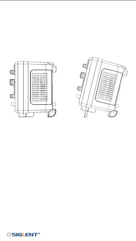
Appearance and Dimensions
Figure 1 Front View (2-channel scope)
Figure 2 Top View (2-channel scope)
3
WWW.SIGLENT.COM

SDS1000X-E User Manual
Figure 3 Front View (4-channel scope)
Figure 4 Top View (4-channel scope)
4
WWW.SIGLENT.COM
SDS1000X-E User Manual
Prepare for Using
Adjust the Supporting Legs
Adjust the supporting legs properly to use them as stands to tilt the oscilloscope upwards for stable placement of the oscilloscope as well as better operation and observation.
Figure 5 Adjust the Supporting Legs
Connect the Power Supply
The power requirements of the oscilloscope are 100-240 V, 50/60Hz or 100-120 V, 400Hz. Please use the power cord supplied with the accessories to connect the oscilloscope to the power source.
5
WWW.SIGLENT.COM

SDS1000X-E User Manual
2-channel scope 4-channel scope
Figure 6 To Connect to Power Supply
Power-on Inspection
When the oscilloscope is energized, press the power key at the lower-left corner of the front panel to start the oscilloscope. During the start-up process, the oscilloscope performs a series of self-tests and you can hear the sound of relay switching. After the self-test is finished, the welcome screen is displayed.
Connect the Probe
Connect the Probe:
1.Connect the BNC terminal of the probe to a channel BNC connector of the oscilloscope at the front panel.
2.Connect the probe tip to the circuit point to be tested and connect the ground alligator clip of the probe to the circuit ground terminal.
Function Inspection
1.Press the Default button on the front panel to restore the instrument to its default configuration.
2.Connect the ground alligator clip of the probe to the “Ground Terminal” under the probe compensation signal output terminal.
6
WWW.SIGLENT.COM
 Loading...