

Page 1

SSA3000X Plus
Spectrum Analyzer
User Manual
UM0703P-E01A
Page 2

SIGLENT
Copyright and Declaration
Copyright
SIGLENT TECHNOLOGIES CO., LTD All Rights Reserved.
Trademark Information
SIGLENT is the registered trademark of SIGLENT TECHNOLOGIES CO., LTD
Declaration
SIGLENT products are protected by patent law worldwide
SIGLENT reserves the right to modify or change parts of or all the specifications or
pricing policies at company’s sole decision.
Information in this publication replaces all previously corresponding material.
Any way of copying, extracting or translating the contents of this manual is not
allowed without the permission of SIGLENT.
SIGLENT will not be responsible for losses caused by either incidental or
consequential in connection with the furnishing, use or performance of this manual
as well as any information contained.
Product Certification
SIGLENT guarantees this product conforms to the national and industrial standards in
China as well as the ISO9001: 2008 standard and the ISO14001: 2004 standard.
Other international standard conformance certification is in progress.
II SSA3000X Plus User Manual
Page 3

SIGLENT
Safety Information
General Safety Summary
Carefully read the following safety precautions to avoid any personal injury or damage to the
instrument and any products connected to it. To avoid potential hazards, please use the
instrument as specified.
Use Proper AC Power Line
Only the power cord designed for the instrument and authorized by the local country should be used.
Ground the Instrument
The instrument is grounded through the protective earth conductor of the power line. To avoid electric
shock, please make sure the instrument is grounded correctly before connecting its input or output
terminals.
Connect the Probe Correctly.
If a probe is used, do not connect the ground lead to high voltage since it has an isobaric electric
potential as the ground.
Look Over All Terminals’ Ratings
To avoid fire or electric shock, please look over all ratings and sign instruction of the instrument. Before
connecting the instrument, please read the manual carefully to gain more information about the ratings.
Use Proper Overvoltage Protection
Make sure that no over-voltage (such as that caused by a thunderstorm) can reach the product, or else
the operator might be exposed to danger of electrical shock.
Electrostatic Prevention
Operate the instrument in an electrostatic discharge protective area environment to avoid damages
induced by static discharge. Always ground both the internal and external conductors of the cable to
release static before connecting.
Maintain Proper Ventilation
Inadequate ventilation may cause increasing of the instrument’s temperature, which will eventually
damage the instrument. So keep well ventilated and inspect the intake and fan regularly.
Avoid Exposed Circuit or Components
Do not touch exposed contacts or components when the power is on.
SSA3000X Plus User Manual III
Page 4
SIGLENT
Terms in this Manual. These terms may appear in this manual:
WARNING
Warning statements indicate the conditions or practices that could
result in injury or loss of life.
CAUTION
Caution statements indicate the conditions or practices that could result
in damage to this product or other property.
Do Not Operate Without Covers
Do not operate the instrument with covers or panels removed.
Use proper Fuse.
Use Only the Specified Fuse.
Keep Product Surfaces Clean and Dry.
To avoid the influence of dust and/or moisture in the air, please keep the surface of the device clean
and dry.
Do Not Operate in Wet Conditions.
In order to avoid short circuiting to the interior of the device or electric shock, please do not operate the
instrument in a humid environment.
Do Not Operate in an Explosive Atmosphere.
In order to avoid damage to the device or personal injury, it is important to operate the device away
from an explosive atmosphere.
Any parts of the device and its accessories are not allowed to be changed or replaced, other than
authorized by the manufacturer or his agent.
Make sure not to position the equipment so that it is difficult to operate the disconnecting device
(detachable plug).
Safety Terms and Symbols
Terms on the product:
DANGER Indicates direct injuries or hazards that may happen.
WARNING Indicates potential injuries or hazards that may happen.
CAUTION Indicates potential damages to the instrument or other property that may happen.
IV SSA3000X Plus User Manual
Page 5
SIGLENT
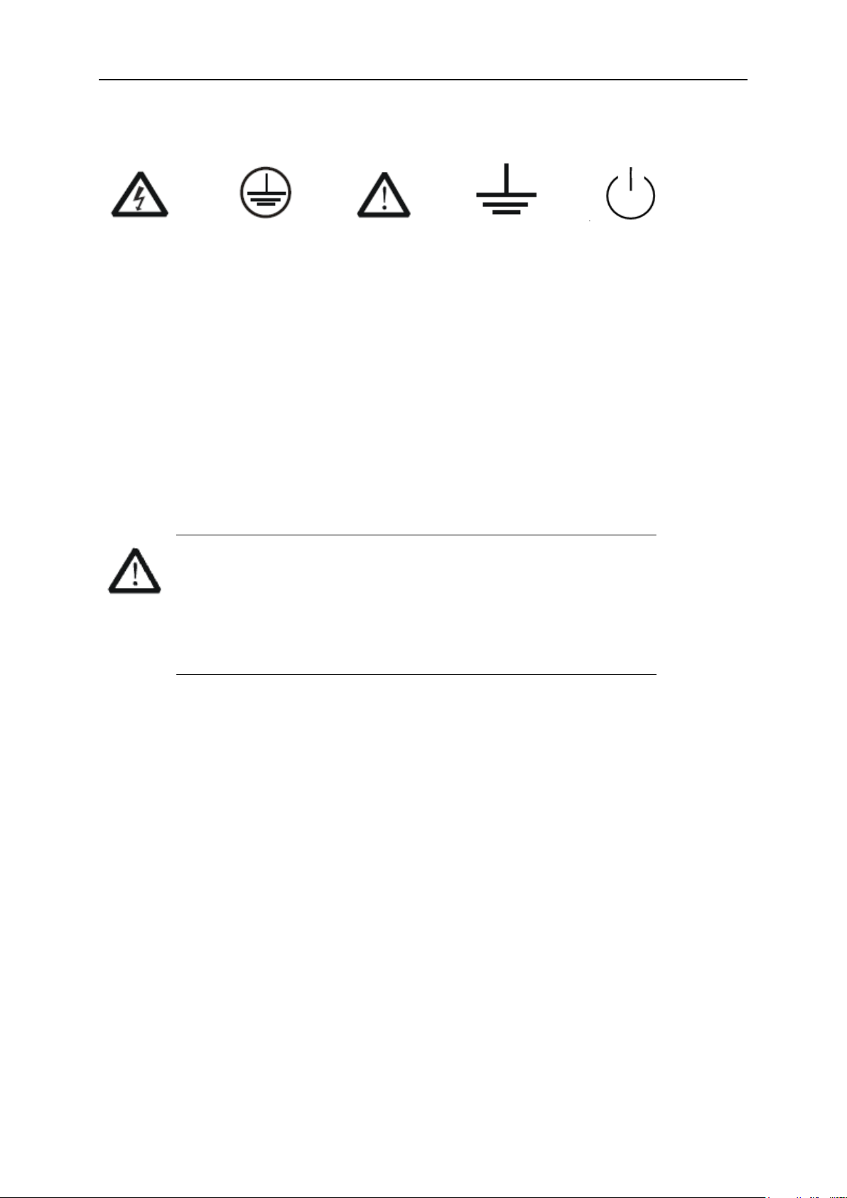
Symbols on the product:
Hazardous protective Earth Warning Test Power Switch
Voltage Terminal Ground
If find such symbols on the product, consult the manual to find out the nature of the potential
hazard and the actions which have to be taken.
Measurement Category
Measurement Categories
This analyzer can make measurements in other circuits that are not directly connected to mains.
WARNING
This analyzer can only be used for measurements within its specified measurement
categories.
Not to use the product for measurements within other measurement
categories, such as CAT II, CAT III, CAT IV.
Not to use the equipment for measurements on mains circuits
Measurement Category Definitions
Measurement category II is for measurements performed on circuits directly connected to the low
voltage installation. Examples are measurements on household appliances, portable tools and
similar equipment.
Measurement category III is for measurements performed in the building installation. Examples
are measurements on distribution boards, circuit-breakers, wiring, including cables, bus-bars,
junction boxes, switches, socket-outlets in the fixed installation, and equipment for industrial use
and some other equipment, for example. Stationary motors with permanent connection to the fixed
installation.
Measurement category IV is for measurements performed at the source of the low-voltage
installation. Examples are electricity meters and measurements on primary over current protection
devices and ripple control units.
SSA3000X Plus User Manual V
Page 6
SIGLENT
Working Environment
Temperature
Operating: 0℃ to +40℃
Non-operation: -20℃ to +70℃
Humidity
Under +35℃: ≤80% relative humidity
+35℃ to +40℃: ≤60% relative humidity
WARNING
To avoid short circuit inside the instrument or electric shock,
please do not operate in humid environment.
Altitude
Operating: less than 3 km
Non-operation: less than 15 km
Degree of protection
IP20
Installation (overvoltage) Category
This product is powered by mains conforming to installation (overvoltage) category II.
WARNING
Make sure that no overvoltage (such as that caused by thunderbolt) can reach the
product, or else the operator might expose to danger of electric shock.
Installation (overvoltage) Category Definitions
Installation (overvoltage) category I refers to signal level which is applicable to equipment
measurement terminals connected to the source circuit. In these terminals, precautions are done
to limit the transient voltage to the corresponding low level.
Installation (overvoltage) category II refers to the local power distribution level which is applicable
to equipment connected to the AC line (AC power).
VI SSA3000X Plus User Manual
Page 7
SIGLENT
Ventilation Requirement
This analyzer uses fan to force cooling. Please make sure that the air intake and exhaust areas
are free from obstructions and have free air. When using the analyzer in a bench-top or rack
setting, provide at least 10 cm clearance beside, above and behind the instrument for adequate
ventilation.
WARNING
Inadequate ventilation may cause temperature increase which would damage the
instrument. So please keep the instrument well ventilated during operation and inspect
the intake and fan regularly.
General Care and Cleaning
Care
Do not store or leave the instrument in direct sunshine for long periods of time.
WARNING
To avoid damages to the instrument or probe, please do not leave them in fog, liquid,
or solvent.
Cleaning
Please perform the following steps to clean the instrument and probe regularly according to its
operating conditions.
1. Disconnect the instrument from all power sources, and then clean it with a soft wet cloth.
2. Clean the loose dust on the outside of the instrument and probe with a soft cloth. When
cleaning the LCD, take care to avoid scarifying it.
WARNING
To avoid damages to the surface of the instrument and probe, please do not use any
corrosive liquid or chemical cleanser.
WARNING
Make sure that the instrument is completely dry before restarting it to avoid short
circuits or personal injuries.
SSA3000X Plus User Manual VII
Page 8

SIGLENT
L'information de sûreté
Résumé général de sûreté
Lisez soigneusement les mesures de sécurité suivantes pour éviter n'importe quelles blessures ou
les dommages à l'instrument et à tous les produits se sont reliés à eux. Pour éviter des risques,
utilisez svp l'instrument comme indiqué.
Employez la ligne à haute tension appropriée
Seulement le cordon de secteur conçu pour l'instrument et autorisé par le pays local a pu être
employé.
A rectifié l'instrument.
L'instrument est fondu par le conducteur protecteur de terra de la ligne à haute tension. Pour
éviter la décharge électrique, le conducteur moulu doit être relié à la terre. Assurez-vous que
l'instrument est fondu correctement avant de relier ses bornes d'entrée ou de rendement.
Reliez le fil de signal correctement.
Le potentiel de l'au sol de fil de signal est égal à la terre, ainsi ne relie pas le fil de signal à une
tension.
Regardez estimations au-dessus de toutes les bornes des'
Pour éviter le feu ou la décharge électrique, regardez svp au-dessus de toutes les estimations et
instruction de signe de l'instrument. Avant de relier l'instrument, lisez svp le manuel
soigneusement pour obtenir plus d'informations sur les estimations.
Employez la protection appropriée de surtension
Assurez-vous qu'aucune surtension (comme cela provoqué par un orage) ne peut atteindre le
produit, ou bien l'opérateur pourrait exposer au danger du choc électrique.
Empêchement électrostatique
Fonctionnez dans un environnement protecteur de secteur de décharge électrostatique pour
éviter des dommages induits par décharge statique. A toujours rectifié les conducteurs internes et
externes du câble pour libérer la charge statique avant de se relier.
La ventilation insatisfaisante de ventilation
bonne de subsistance peut causer l'augmentation de la température, qui endommagera par la
suite l'instrument. Gardez ainsi la ventilation bonne et inspectez la prise et éventez régulièrement.
Évitez le circuit ou les composants exposés
ne touchent pas les contacts ou les composants exposés quand le courant passe.
VIII SSA3000X Plus User Manual
Page 9

SIGLENT
Employez l'utilisation appropriée
de fusible seulement le fusible indiqué.
Ne fonctionnez pas sans couvertures
n'actionnent pas l'instrument des couvertures ou des panneaux étant coupés.
Ne fonctionnez pas avec des échecs suspectés.
Si vous suspectez les dommages se produisent à l'instrument, l'ont inspecté par le personnel de
service qualifié avant d'autres opérations. N'importe quel entretien, ajustement ou remplacement
particulièrement aux circuits ou aux accessoires doivent être exécutés par le personnel autorisé
par SIGLENT.
Ne fonctionnez pas en conditions humides.
Afin d'éviter de court-circuiter à l'intérieur du dispositif ou de la décharge électrique, svp ne
fonctionnez pas dans un environnement humide.
Do Not Operate in an Explosive Atmosphere.
Ne fonctionnez pas dans une atmosphère explosive.
Afin d'éviter d'endommager le dispositif ou les blessures, il est important d'utiliser le dispositif loin
à partir d'une atmosphère explosive.
Maintenez les surfaces de produit propres et sèches.
Pour éviter l'influence de la poussière et/ou de l'humidité en air, maintenez svp la surface du
dispositif propre et sèche.
En manipulant la sûreté
manipulez svp avec soin pendant le transport pour éviter d'endommager des boutons, des
interfaces de bouton et d'autres parties sur les panneaux.
Le corps ou l'opérateur responsable devrait se référer au manuel d'instruction pour préserver la
protection se permettent par l'équipement. Si l'équipement est utilisé en quelque sorte non indiqué
par le fabricant, la protection fournie par l'équipement peut être altérée.
On ne permet à aucune pièce du dispositif et de ses accessoires d'être changé ou remplacé, autre
qu'autorisé par le fabricant ou son agent.
Pas placez l'équipement de sorte qu'il soit difficile d'utiliser le dispositif débranchant (prise
détachable).
SSA3000X Plus User Manual IX
Page 10
SIGLENT
Limites en ce manuel. Ces limites peuvent apparaître en ce manuel :
Les rapports
d'avertissement D'AVERTISSEMENT indiquent les conditions ou les
pratiques qui pourraient avoir comme conséquence les dommages ou la
perte de la ie.
Les rapports
d'attention d'ATTENTION indiquent les conditions ou les pratiques qui
pourraient avoir comme consequenceles dommages à ce produit ou à
toute autre propriété.
Limites et symboles de sûreté
Limites sur le produit. Ces limites peuvent apparaître sur le produit :
Le DANGER indique les dommages ou les risques directs qui peuvent se produire.
Dommages ou risques potentiels de WARNINGIndicates qui peuvent se produire.
L'ATTENTION indique des dommages potentiels à l'instrument ou à toute autre propriété qui
peuvent se produire.
Si la trouvaille de tels symboles sur le produit, consultent le manuel pour découvrir la nature du
risque et des actions qui doivent être pris.
Symboles sur le produit. Ces symboles peuvent apparaître sur le produit :
Dangereux Protecteur Avertissement Châssis Puissance
Tension Au sol de la terre Ground Switch
X SSA3000X Plus User Manual
Page 11
SIGLENT
Catégorie de mesure
Les analyzers peuvent faire des mesures dans d'autres circuits qui ne sont pas directement reliés
aux forces. Pour ne pas employer le produit pour des mesures dans d'autres catégories de
mesure, telles que le CAT II, CAT III, CAT IV.
Ne pas utiliser l'équipement pour des mesures sur des forces circuite, pour ne pas utiliser
l'équipement pour des mesures sur la tension excèdent la gamme de tension décrivent dans le
manuel.
Les rapports
cet analyzers peut seulement être employé pour des mesures dans
ses catégories indiquées de mesure.
La catégorie II de mesure
de définitions de catégorie de mesure est pour des mesures effectuées sur des circuits
directement reliés à l'installation de basse tension. Les exemples sont des mesures sur des
appareils électroménagers, des outils portatifs et l'équipement semblable.
La catégorie III de mesure est pour des mesures effectuées dans l'installation de bâtiment. Les
exemples sont des mesures sur des conseils de distribution, des disjoncteurs, le câblage, y
compris des câbles, des barres omnibus, des boîtes de jonction, des commutateurs, des
douille-sorties dans l'installation fixe, et l'équipement à l'utilisation industrielle et à un autre
équipement,
par exemple. Moteurs stationnaires avec le raccordement permanent à l'installation fixe.
La catégorie IV de mesure est pour des mesures effectuées à la source d'installation de basse
tension.Les exemples sont des mètres et des mesures de l'électricité sur les dispositifs de
protection d'excédent primaire et les unités de commande courants d'ondulation.
SSA3000X Plus User Manual XI
Page 12
SIGLENT
Environnement de fonctionnement
Température
En fonctionnement: 0 à + 40
Non-fonctionnement: -20 à + 70
Humidité
Moins de + 35: humidité relative ≤80%
+ 35 à + 40 ℃: humidité relative ≤60%
EN AVERTISSANT
d'éviter le court-circuit à l'intérieur de l'instrument ou de la décharge électrique, svp ne
fonctionnez pas dans l'environnement humide.
Opération
d'altitude : moins de 3 kilomètres
de non-fonctionnement : moins de 15 kilomètres
Degré de protection
IP20
La catégorie d'installation (surtension)
ce produit est actionnée par des forces conformément à la catégorie II. d'installation (surtension).
EN AVERTISSANT
assurez-vous qu'aucune surtension (comme cela provoqué par coup de
foudre) ne peut atteindre le produit, ou bien l'opérateur pourrait
exposer au danger de la décharge électrique.
La catégorie II d'installation de définitions de catégorie d'installation (surtension) (surtension) se
rapporte au niveau local de distribution d'énergie qui est applicable à l'équipement relié à la ligne à
C.A. (courant alternatif).
Condition de ventilation
This analyzer uses fan to force cooling. Please make sure that the air intake and exhaust areas
are free from obstructions and have free air. When using the analyzer in a bench-top or rack
setting, provide at least 10 cm clearance beside, above and behind the instrument for adequate
ventilation.
XII SSA3000X Plus User Manual
Page 13
SIGLENT
Cet analyzer utilise le ventilateur pour forcer le refroidissement. Veuillez s'assurer que les
secteurs d'entrée et d'échappement d'air sont exempts des obstructions et ont l'air libre. À l'aide
de l'analyzer dans un mettre hors jeu-dessus ou un arrangement de support, fournissez au moins
le dégagement de 10 centimètres près, au-dessus et derrière de l'instrument pour à ventilation
proportionnée.
La ventilation insatisfaisante peut causer l'augmentation de la température qui
endommagerait l'instrument. Veuillez ainsi la subsistance l'instrument bien aéré lors
du fonctionnement et inspectez la prise et éventez régulièrement.
Soin général et nettoyage
Ne stockez pas ou ne laissez pas l'instrument en soleil direct pendant de longues périodes.
Pour éviter d'endommager l'instrument, svp ne les laissez pas dans le brouillard, le
liquide, ou le dissolvant.
nettoyage
Veuillez exécuter les étapes suivantes pour nettoyer l'instrument régulièrement selon ses
conditions de fonctionnement.
1. Démontez l'instrument de toutes les sources d'énergie, et puis nettoyez-le avec un tissu humide
mou.
2. Nettoyez la poussière lâche sur l'extérieur de l'instrument avec un tissu mou. En nettoyant
l'affichage à cristaux liquides, salut pour éviter de le scarifier.
Pour éviter d'endommager la surface de l'instrument, svp n'utilisez aucune épierreuse
corrosive de liquide ou de produit chimique.
Assurez-vous que l'instrument est complètement sec avant de le remettre en marche
pour éviter des courts-circuits ou des blessures.
SSA3000X Plus User Manual XIII
Page 14

SIGLENT
Allgemeine Sicherheitshinweise
Um Verletzungen oder Schäden am Gerät und den damit verbundenen Produkten zu
vermeiden, lesen Sie die folgenden Sicherheitshinweise sorgfältig durch.
Um mögliche Gefahren zu vermeiden, verwenden Sie bitte das Gerät wie angegeben.
Wartungsarbeiten an diesem Gerät dürfen nur von qualifiziertem Reparaturpersonal
durchgeführt werden.
Verwendung eines geeigneten Netzkabels
Verwenden Sie nur das für das Gerät vorgesehene und von den örtlichen Behörden
zugelassene Netzkabel.
Erdung des Gerätes
Das Gerät ist über den Schutzleiter des Netzkabels geerdet. Um einen elektrischen Schlag zu
vermeiden, vergewissern Sie sich bitte, bevor Sie seine Eingangs- oder Ausgangsklemmen
anschließen, dass das Gerät korrekt geerdet ist.
Anschluss der Signalleitung
Die Masse der Signalleitung ist auf dem gleichen Potential wie die Erdung des Gerätes.
Schließen Sie daher die Masseleitung nie an eine Hochspannung an. Berühren Sie keine
freiliegenden Kontakte oder Komponenten.
Verschaffen Sie sich einen Überblick über alle Anschluss-Ratings
Um Brände oder Stromschläge zu vermeiden, lesen Sie bitte alle Bemerkungen und
Anweisungen des Gerätes. Bevor Sie das Gerät anschließen, lesen Sie bitte das Handbuch
sorgfältig durch, um weitere Informationen über die Nennleistungen zu erhalten.
Betreiben Sie kein Gerät, bei dem der Verdacht besteht, dass es defekt ist.
Wenn Sie vermuten, dass das Produkt beschädigt ist, lassen Sie es bitte von qualifiziertem
Fachpersonal überprüfen. Vermeiden Sie den Kontakt mit freiliegenden Stromkreisen oder
Drähten. Berühren Sie keine freiliegenden Kontakte oder Komponenten, wenn das Gerät
eingeschaltet ist.
Verwenden Sie einen geeigneten Überspannungsschutz
Stellen Sie sicher, dass keine Überspannung (z.B. durch ein Gewitter) auf das Produkt
gelangen kann, da sonst der Bediener der Gefahr eines Stromschlags ausgesetzt sein kann.
Nicht ohne Abdeckungen betreiben
Betreiben Sie das Gerät nicht bei abgenommenen Abdeckungen oder Platten.
Halten Sie die Oberfläche des Gerätes sauber und trocken.
Nicht unter nassen/feuchten Bedingungen betreiben.
Betreiben Sie das Gerät nicht in einer explosiven Atmosphäre.
Vermeiden Sie es, dieses Gerät einem Feuer auszusetzen.
XIV SSA3000X Plus User Manual
Page 15
SIGLENT
Sicherheitshinweise und Symbole
In diesem Produkt verwendete Begriffe. Diese Begriffe können im Produkt erscheinen:
GEFAHR weist auf eine mögliche, sofortige und direkte Verletzung oder Gefährdung hin.
WARNUNG weist auf möglicherweise auftretende Verletzungen oder Gefahren hin
VORSICHT weist auf möglicherweise auftretende Schäden am Gerät oder anderen
Gegenständen
hin
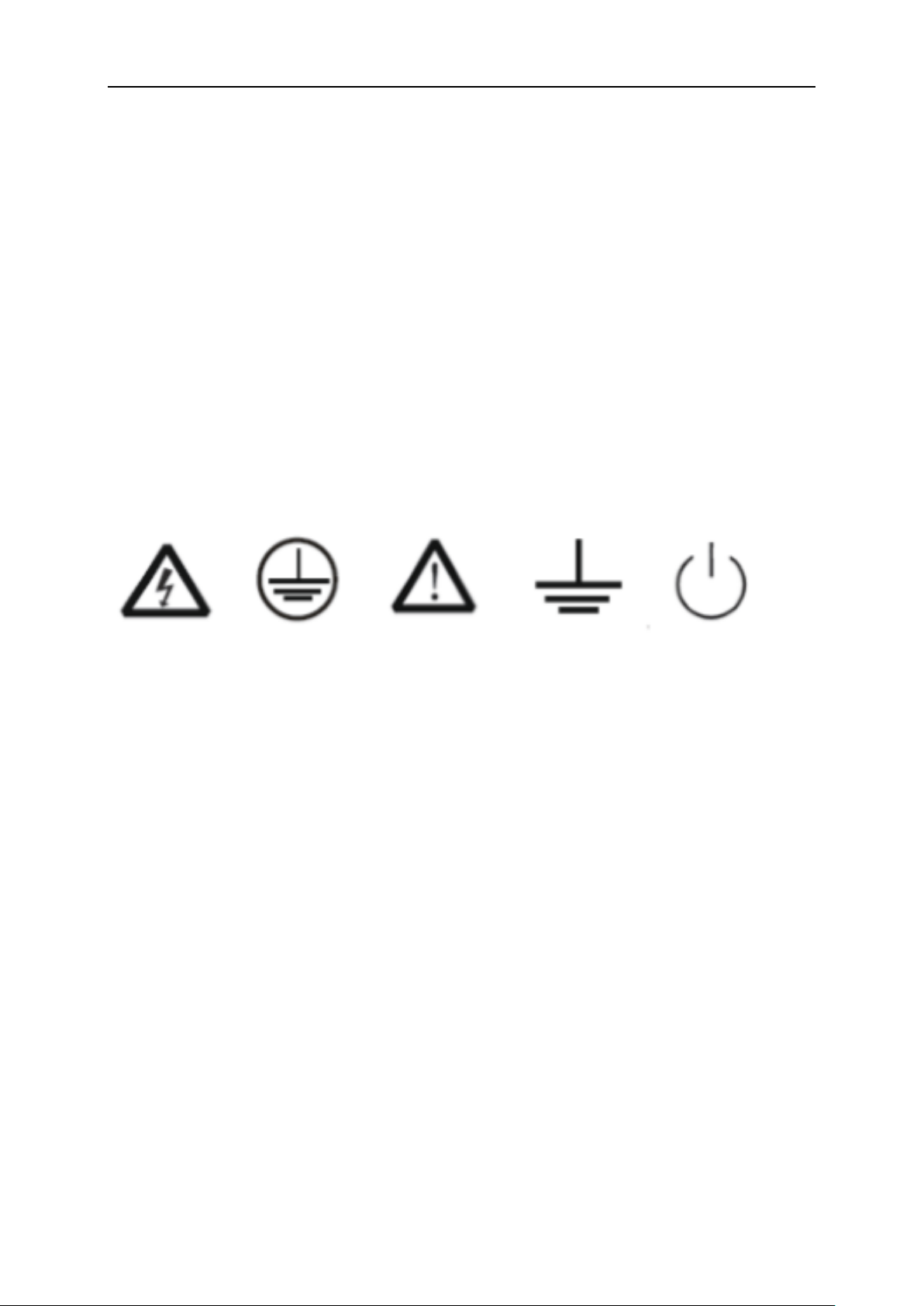
In diesem Produkt verwendete Symbole. Diese Symbole können auf dem Produkt
erscheinen:
Gefährliche Schutzerde Sicherheitswarnung Erdung Netzschalter
Spannung
SSA3000X Plus User Manual XV
Page 16

SIGLENT
Contents
Copyright and Declaration ............................................................................................................. II
Safety Information ......................................................................................................................... III
General Safety Summary .............................................................................................................. III
Safety Terms and Symbols........................................................................................................... IV
Measurement Category ................................................................................................................. V
Working Environment ................................................................................................................... VI
Ventilation Requirement .............................................................................................................. VII
General Care and Cleaning ......................................................................................................... VII
L'information de sûreté .............................................................................................................. VIII
Résumé général de sûreté ......................................................................................................... VIII
Limites et symboles de sûreté ...................................................................................................... X
Catégorie de mesure ..................................................................................................................... XI
Environnement de fonctionnement ............................................................................................ XII
Condition de ventilation .............................................................................................................. XII
Soin général et nettoyage .......................................................................................................... XIII
Allgemeine Sicherheitshinweise ............................................................................................... XIV
Sicherheitshinweise und Symbole .............................................................................................XV
Chapter 1 Quick Start ................................................................................................................. 2
1.1 General Inspection ............................................................................................................ 3
1.2 Appearance and Dimension ............................................................................................. 3
1.3 Preparing for Use .............................................................................................................. 4
1.3.1 Adjust the Supporting Legs ....................................................................................... 4
1.3.2 Connect to AC Power Supply .................................................................................... 4
1.4 Front Panel ....................................................................................................................... 5
1.4.1 Front Panel Function Keys ........................................................................................ 5
1.4.2 Front Panel Key Backlight ......................................................................................... 7
1.4.3 Using the Numeric Keyboard .................................................................................... 7
1.4.4 Front Panel Connectors ............................................................................................ 8
1.5 Rear Panel ...................................................................................................................... 10
1.6 User Interface ................................................................................................................. 12
1.7 Firmware Operation ........................................................................................................ 14
1.7.1 Check System Information ...................................................................................... 14
1.7.2 Load Option ............................................................................................................. 14
1.7.3 Firmware Upgrade .................................................................................................. 14
1.8 Touch Operation ............................................................................................................. 14
1.9 Remote Control ............................................................................................................... 15
1.10 Using Built-in Help .......................................................................................................... 15
1.11 Using the Security Lock .................................................................................................. 16
Chapter 2 Spectrum Analyzer ................................................................................................... 17
2.1 Basic Settings ................................................................................................................. 18
2.1.1 Frequency ............................................................................................................... 18
2.1.2 Span ........................................................................................................................ 23
2.1.3 Amplitude ................................................................................................................ 24
XVI SSA3000X Plus User Manual
Page 17

SIGLENT
2.1.4 Auto Tune ................................................................................................................ 28
2.2 Sweep and Functions ..................................................................................................... 30
2.2.1 BW ........................................................................................................................... 30
2.2.2 Trace ....................................................................................................................... 32
2.2.3 Detect ...................................................................................................................... 34
2.2.4 Sweep ..................................................................................................................... 35
2.2.5 Trigger ..................................................................................................................... 37
2.2.6 Limit ......................................................................................................................... 38
2.2.7 TG (Tracking Generator) ......................................................................................... 39
2.2.8 Demod ..................................................................................................................... 42
2.3 Marker ............................................................................................................................. 44
2.3.1 Marker ..................................................................................................................... 44
2.3.2 Marker -> ................................................................................................................. 47
2.3.3 Marker Fn ................................................................................................................ 48
2.3.4 Peak ........................................................................................................................ 50
2.4 Measurement .................................................................................................................. 53
2.4.1 Meas........................................................................................................................ 53
2.4.2 Meas setup .............................................................................................................. 54
Chapter 3 Modulation Analyzer ................................................................................................. 64
3.1 Basic Settings ................................................................................................................. 65
3.1.1 Frequency ............................................................................................................... 65
3.2 Measurement .................................................................................................................. 65
3.2.1 Digital Modulation Analysis ..................................................................................... 65
3.2.2 Analog Modulation Analysis .................................................................................... 69
3.3 Sweep and Functions ..................................................................................................... 70
3.3.1 Trigger ..................................................................................................................... 70
3.3.2 Sweep ..................................................................................................................... 71
Chapter 4 System Settings ....................................................................................................... 72
4.1 System ............................................................................................................................ 72
4.1.1 Language ................................................................................................................ 72
4.1.2 Power On/Preset ..................................................................................................... 72
4.1.3 Interface .................................................................................................................. 73
4.1.4 Calibration ............................................................................................................... 74
4.1.5 System Info ............................................................................................................. 74
4.1.6 Date and Time ......................................................................................................... 75
4.1.7 Self Test ................................................................................................................... 76
4.2 Display ............................................................................................................................ 76
4.2.1 Grid Brightness ....................................................................................................... 76
4.2.2 Screenshot .............................................................................................................. 76
4.2.3 Touch Settings ......................................................................................................... 77
4.2.4 Power Saving .......................................................................................................... 78
4.2.5 Annotation ............................................................................................................... 78
4.2.6 Display Line ............................................................................................................. 78
4.3 File .................................................................................................................................. 79
4.3.1 Browser ................................................................................................................... 79
SSA3000X Plus User Manual XVII
Page 18

SIGLENT
4.3.2 Open/Load .............................................................................................................. 79
4.3.3 Back ........................................................................................................................ 79
4.3.4 View Type ................................................................................................................ 79
4.3.5 Save Type ............................................................................................................... 79
4.3.6 Save ........................................................................................................................ 80
4.3.7 Create Folder .......................................................................................................... 80
4.3.8 Operate ................................................................................................................... 80
4.4 Shortcut Key ................................................................................................................... 81
4.4.1 Preset ...................................................................................................................... 81
4.4.2 Couple ..................................................................................................................... 87
4.4.3 Help ......................................................................................................................... 88
4.4.4 Save ........................................................................................................................ 88
Chapter 5 Programming Overview ........................................................................................... 89
5.1 Remotely Operating the Analyzer ................................................................................... 89
5.1.1 USB: Connecting the Analyzer via the USB Device port ........................................ 89
5.1.2 LAN: Connecting the Analyzer via the LAN port ..................................................... 89
5.1.3 GPIB: Connecting the Analyzer via the USB-Host port .......................................... 90
5.2 Build Communication ...................................................................................................... 91
5.2.1 Build Communication Using VISA ........................................................................... 91
5.2.2 Build Communication Using Sockets/Telnet ........................................................... 93
5.3 Remote Control Capabilities ........................................................................................... 94
5.3.1 User-defined Programming ..................................................................................... 94
5.3.2 Send SCPI Commands via NI MAX ........................................................................ 94
5.3.3 Easy Spectrum Software......................................................................................... 96
5.3.1 Web Control ............................................................................................................ 97
Chapter 6 Service and Support ................................................................................................ 98
6.1 Service Summary ........................................................................................................... 98
6.2 Troubleshooting .............................................................................................................. 98
6.3 Contact Us .................................................................................................................... 100
XVIII SSA3000X Plus User Manual
Page 19

Page 20

SIGLENT
Chapter 1 Quick Start
This chapter guides users to quickly get familiar with the appearance, dimensions, front/rear panel and
the user interface, as well as announcements during the first use of the analyzer.
Subjects in this chapter:
General Inspection
Appearance and Dimension
Preparing for Use
Front Panel
Rear Panel
User Interface
Firmware Operation
Touch Operation
Remote Control
Using Built-in Help
Using the Security Lock
2 SSA3000X Plus User Manual
Page 21
SIGLENT
1.1 General Inspection
1. Inspect the shipping container
Keep the damaged shipping container or cushioning material until the contents of the shipment have
been completely checked and the instrument has passed both electrical and mechanical tests.
The consigner or carrier will be responsible for damages to the instrument resulting from shipment.
SIGLENT will not provide free maintenance or replacement.
2. Inspect the instrument
If the instrument is found to be damaged, defective or fails in electrical or mechanical tests, please
contact SIGLENT.
3. Check the accessories
Please check the accessories according to the packing list in the box. If the accessories are incomplete
or damaged, please contact your SIGLENT sales representative.
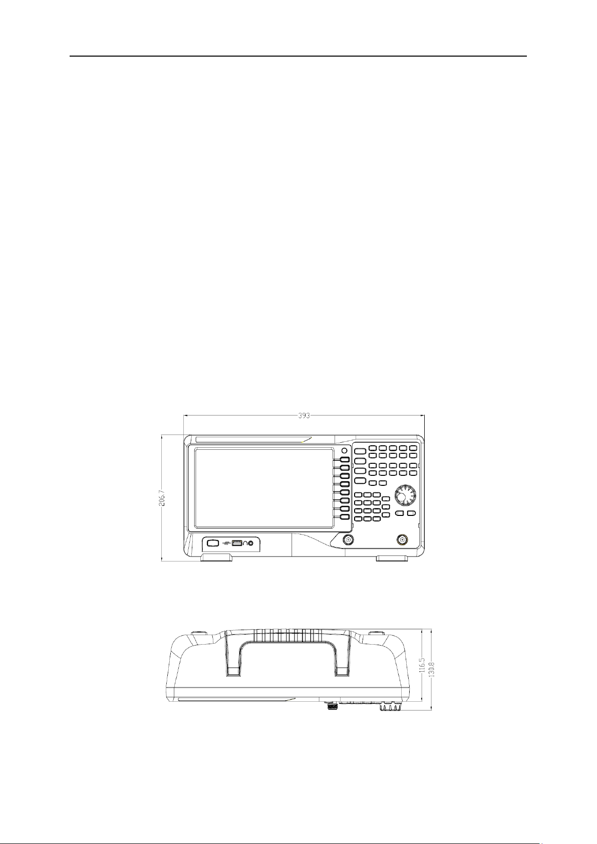
1.2 Appearance and Dimension
Figure 1-1 Front View
Figure 1-2 Top View
SSA3000X Plus User Manual 3
Page 22
SIGLENT
The Plug
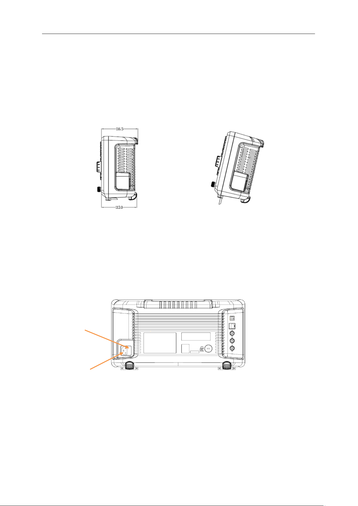
Fuse holder
1.3 Preparing for Use
1.3.1 Adjust the Supporting Legs
Adjust the supporting legs properly to use them as stands to tilt the analyzer upwards for stable
placement as well as easier operation and observation of the instrument display.
Figure 1-3 before adjusting Figure 1-4 after adjusting
1.3.2 Connect to AC Power Supply
The spectrum analyzer accepts 100-240V, 50/60Hz or 100-120V 400Hz AC power supply. Please use
the provided power cord to connect the instrument to the power source as shown in the figure below.
Before powering on, make sure the analyzer is protected by a fuse.
Figure 1-5 Power Cord Connection
4 SSA3000X Plus User Manual
Page 23
1.4 Front Panel
NO.
Description
NO.
Description
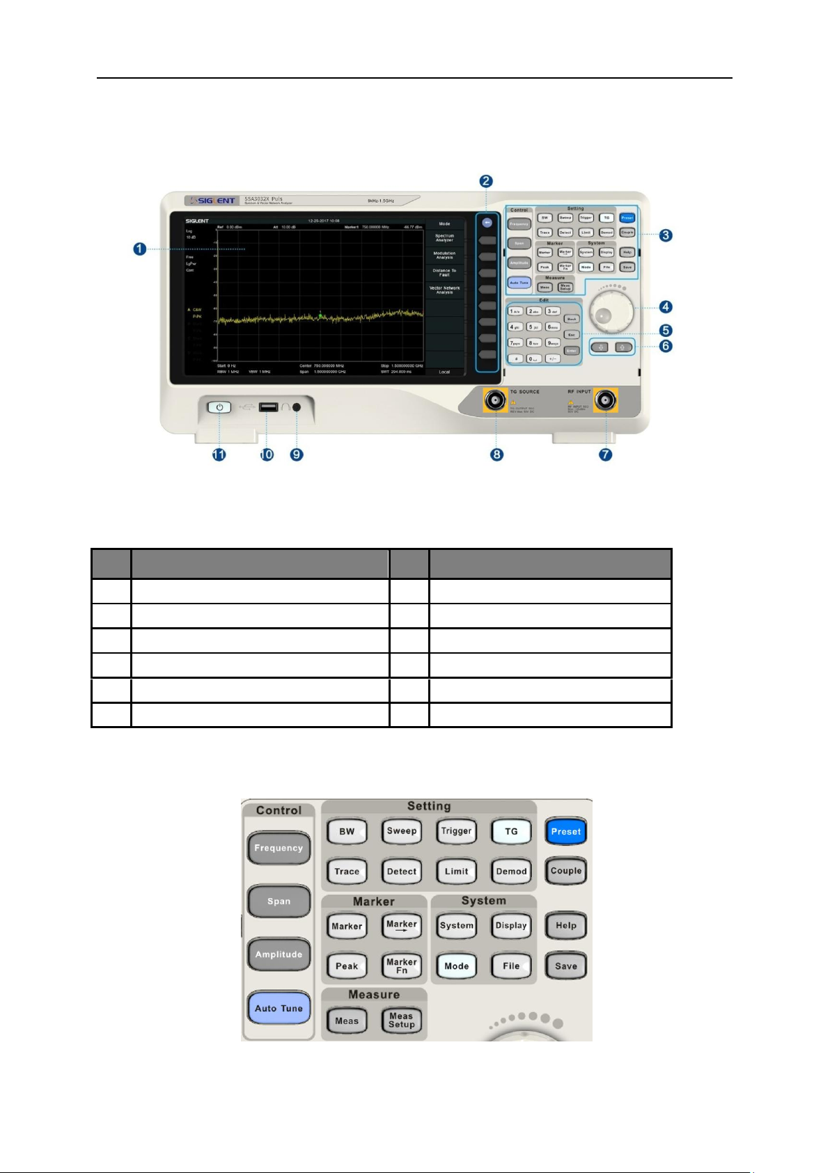
1
User Graphical Interface, touch support
7
RF Input
2
Menu Control Keys
8
TG Output
3
Function Keys
9
3.5 mm Earphone interface
4
Knob
10
USB Host
5
Numeric / Letter Keyboard
11
Power Switch
6
Arrow Keys
SIGLENT
Figure 1-6 the Front Panel
Table 1-1 Front Panel Description
1.4.1 Front Panel Function Keys
Figure 1-7 Function Keys area
SSA3000X Plus User Manual 5
Page 24
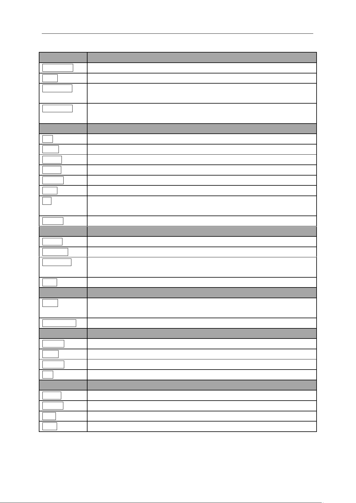
SIGLENT
Control Keys
Description
Frequency
Set the parameters of frequency, and Peak→CF, CF→Step.
Span
Set the parameters of span, and X-scale (Log-Linear) setup.
Amplitude
Set the parameters of amplitude, including Ref Level, Attenuator, Preamp, etc.; and
Correction setup.
Auto Tune
Scan the full span rapidly and move the biggest signal to center freq, and
automatically sets the optimal parameters according to the signal.
Setting Keys
Description
BW
Set the parameters of RBW and VBW, Average Type (Log power, Power, Voltage).
Trace
Select Trace, Trace setup and Trace math.
Sweep
Set the parameters of sweep, and EMI QPD Dwell Time.
Detect
Select the detector type for each trace independently.
Trigger
Select triggers in Free Trigger, Video Trigger and External Trigger.
Limit
Set the Pass\Fail Limit.
TG
Set the parameters of tracking generator. Including TG Level, TG Level offset
Normalization setup. The backlight LED is on when TG source is working.
Demod
Set the demodulation parameters of the AM and FM for audio listening.
Marker Keys
Description
Marker
Set the Markers and Marker Table.
Marker->
Set other system parameters on the basis of the current marker’s value.
Marker Fn
Special functions of the marker such as noise marker, N dB bandwidth measurement
and frequency counter.
Peak
Search for the peak signal, peak search configuration and peak table.
Meas Keys
Description
Meas
In spectrum analyzer mode, selects the Advanced Measurement function.
In non-spectrum analyzer mode, select corresponding settings.
Meas Setup
Set the measurement parameters.
System Keys
Description
System
Set the system parameters.
Mode
Select the working modes.
Display
Set the display parameters.
File
Use the file system and files.
Shortcut Keys
Description
Preset
Sets the system to certain status.
Couple
Set the parameters of some functions between auto and manual.
Help
Turn on the built-in help.
Save
Save Shortcut Key.
Table 1-2 Function keys description
6 SSA3000X Plus User Manual
Page 25
SIGLENT
1.4.2 Front Panel Key Backlight
The on/off state and the color of the backlights of some keys at the front panel indicate the working
state of the analyzer. The states are as listed below.
1. Power Switch
Flash on and off alternatively, in a “breathing” state: indicate the unit is in stand-by.
Constant on: indicates the instrument is in normal operating state.
2. Mode
When the function is Spectrum Analyzer, the backlight turns off. When in other modes, the backlight
turns on.
3. TG
When the TG source is on, the backlight of TG turns on and turns off when the function is off.
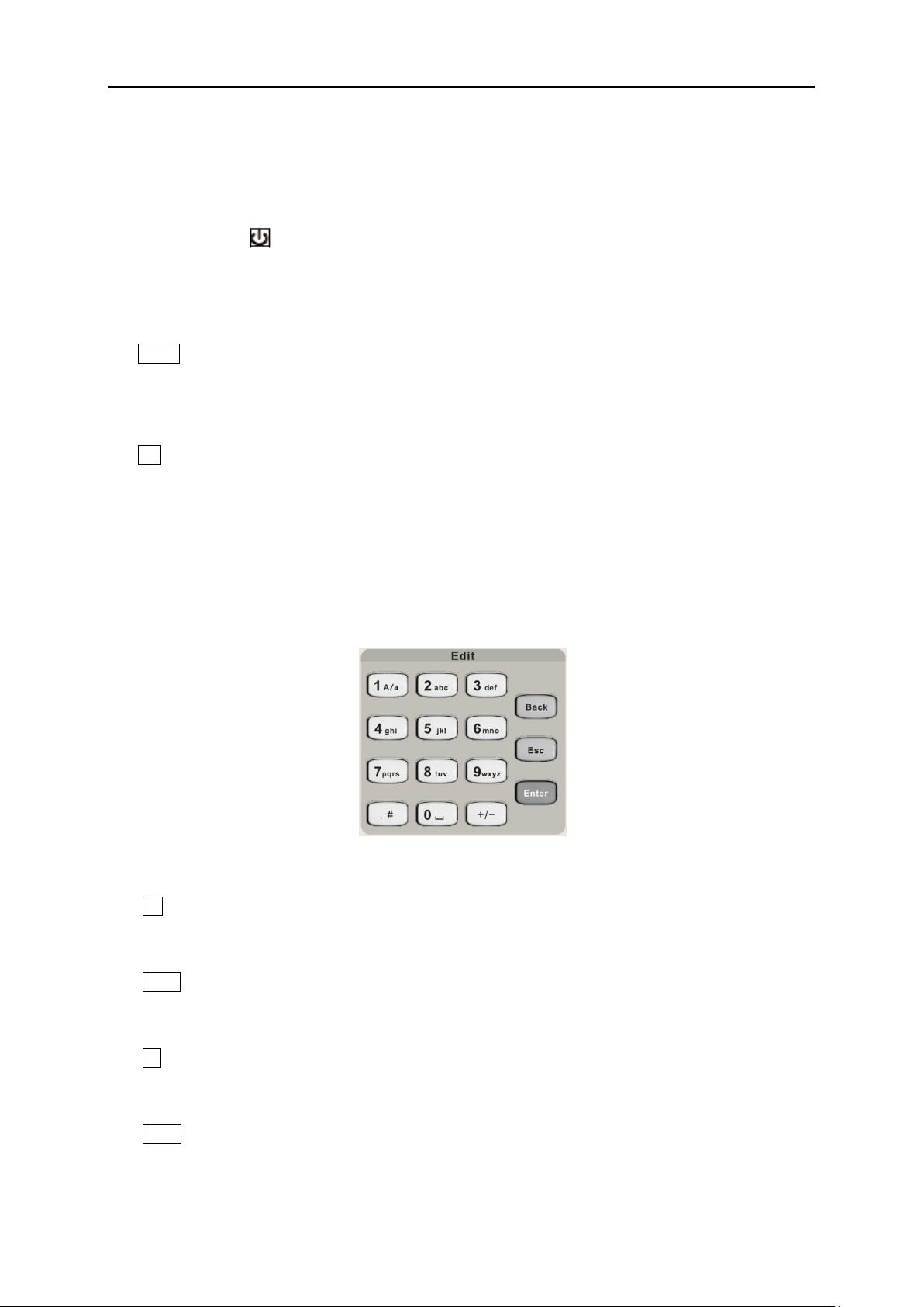
1.4.3 Using the Numeric Keyboard
The analyzer provides a numeric keyboard at the front panel. The numeric keyboard supports English
uppercase/lowercase characters, numbers and common symbols (including decimal point, #, space
and +/-) and are mainly used to edit file or folder names and set parameters.
Figure 1-8 Numeric Keyboards
1. +/-
In number input, set the sign of number; in file input, switch in number and letter.
2. 1 A/a
In number input, enter number 1; in file input, switch between uppercase and lowercase letter.
3. . #
In number input, enter a decimal point. In English input, enter special characters.
4. Back
In parameter editing, press this key to delete the character on the left of the cursor.
SSA3000X Plus User Manual 7
Page 26
SIGLENT
1 2 3
CAUTION
Protect your hearing. Please turn the volume down to zero before using the
earphone. Gradually turn the volume up to a comfortable level after putting
in the earphone.
5. Esc
During parameter editing process, press this key to clear the inputs in the active function area and
exit parameter input.
When the instrument is in remote mode, use this key to return to local mode.
6. Enter
In parameter editing, the system will complete the input and insert a default unit for the parameter.
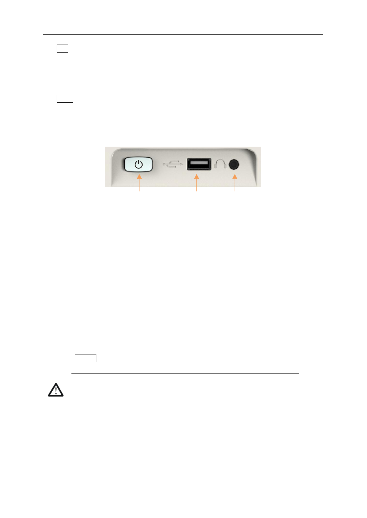
1.4.4 Front Panel Connectors
Figure 1-9 Front Panel Connectors (1)
1. Power Switch
Power on / Power down the instrument
2. USB Host
The analyzer can serve as a “host” device to connect external USB devices. This interface is
available for USB storage devices, the SIGLENT GPIB-USB adapter, wireless or wired mouse and
keyboard.
Read and write functions for an external USB storage device or store the contents currently
displayed on the screen in the USB storage device in .png or .jpg or .bmp format.
3. Earphone Jack
The analyzer can demodulate AM and FM signals. Insert a 3.5 mm earphone into to the jack to acquire
the audio output of the demodulated signal. You can turn on or off the earphone output and adjust the
volume via Demod ->Volume.
8 SSA3000X Plus User Manual
Page 27
SIGLENT
CAUTION
To avoid damaging to the tracking generator, the reverse DC voltage cannot
exceed 50 V
CAUTION
To avoid damaging to the instrument, the RF input signal must meet the
following: The DC voltage component and the maximum continuous power
of the AC (RF) signal component cannot exceed 50 V and +30 dBm
respectively.
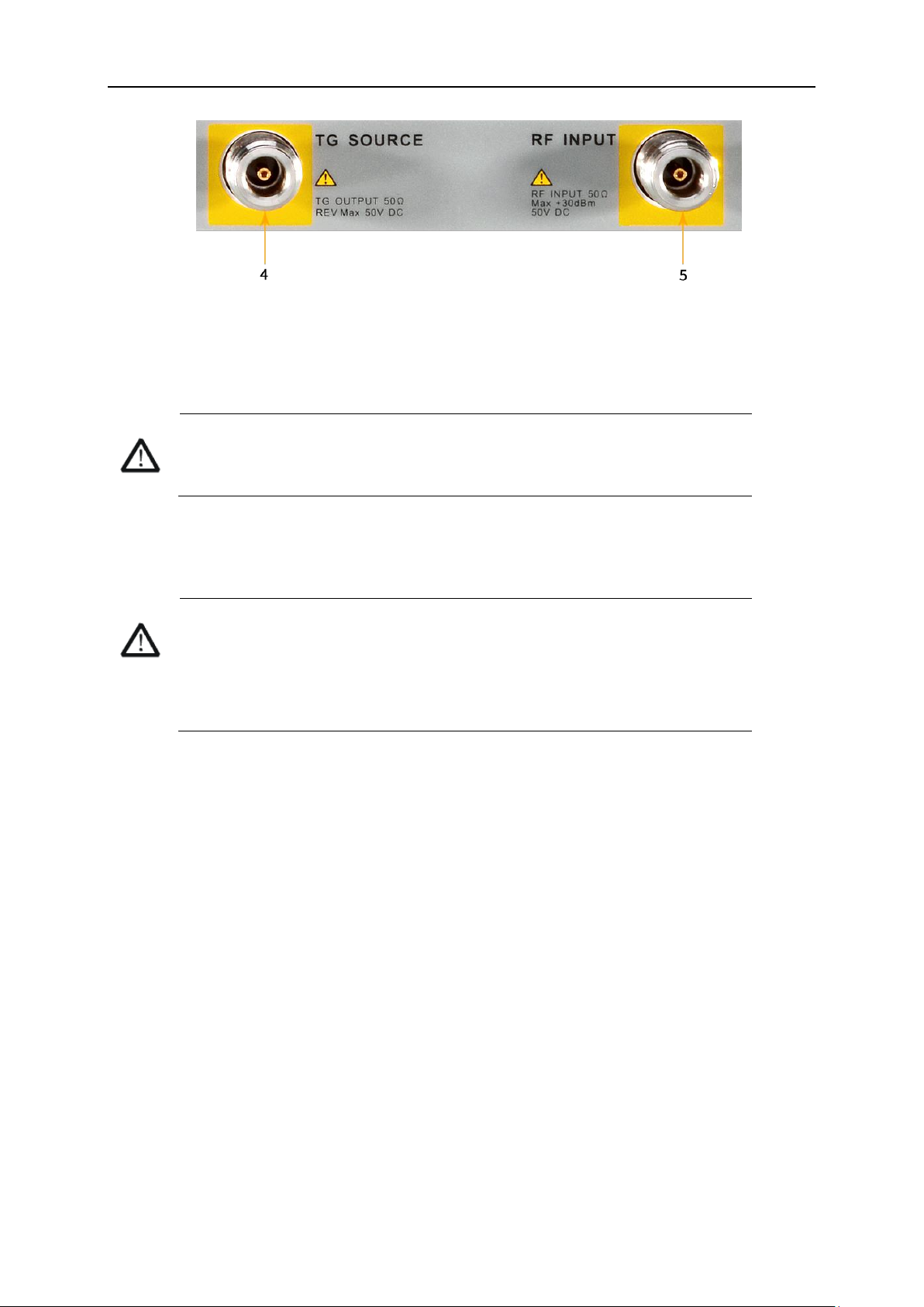
Figure 1-10 Front Panel Connectors (2)
4. TG SOURCE
The TG SOURCE can be connected to a device-under-test (DUT) through a cable with a male N-type
male connector.
5. RF INPUT
The RF INPUT can be connected to the DUT through a cable with a male N-type connector
SSA3000X Plus User Manual 9
Page 28
SIGLENT
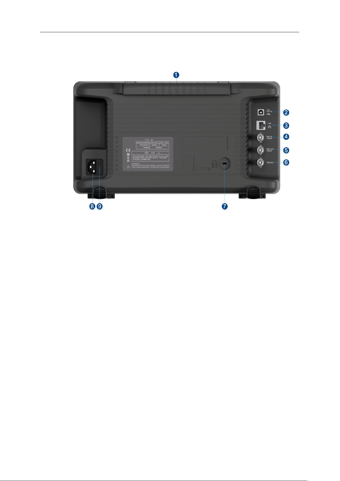
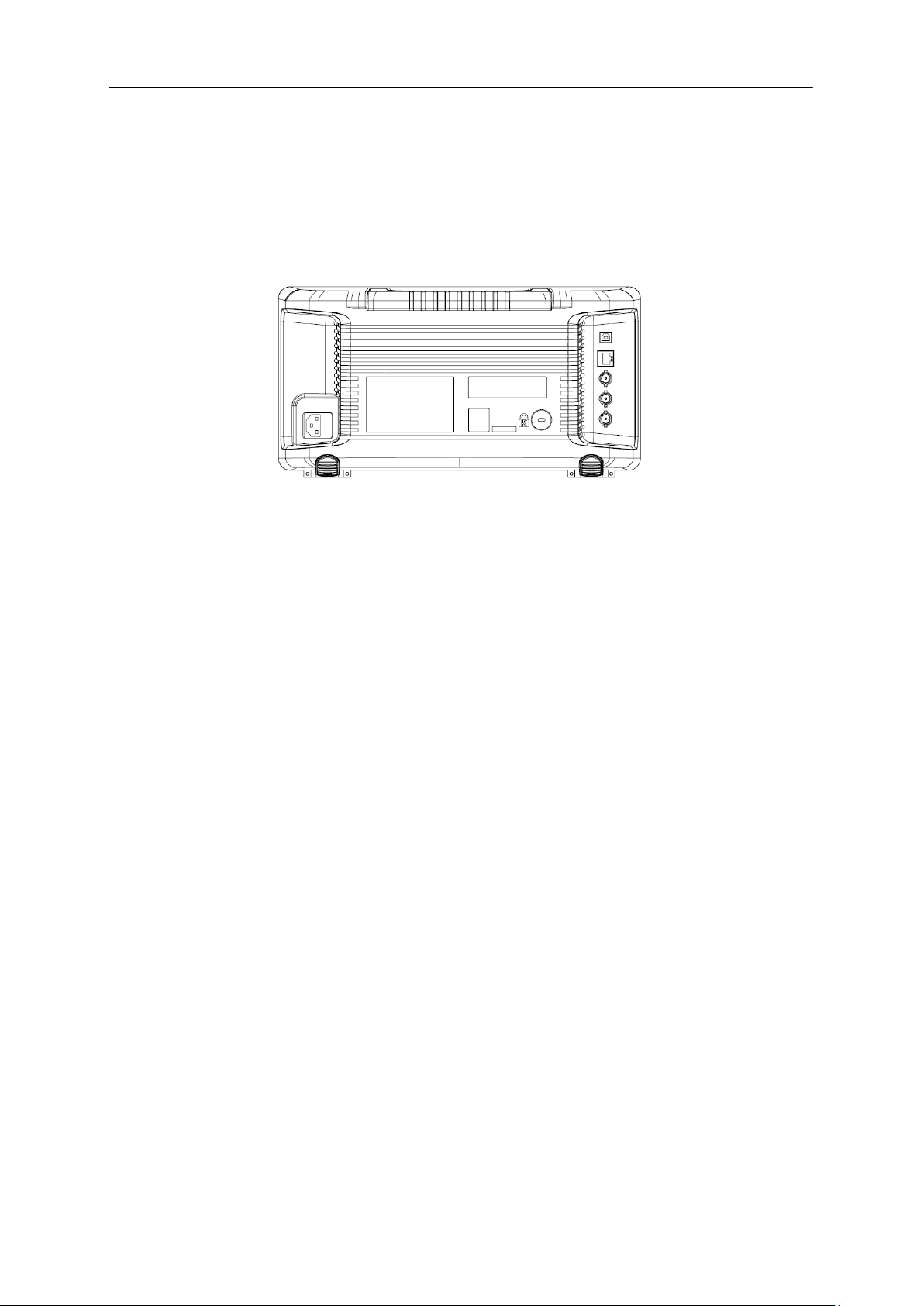
1.5 Rear Panel
Figure 1-11 Rear Panel
1. Handle
Pull up the handle vertically for easy carrying of the instrument. When you do not need the handle,
press it down.
2. USB Device Interface
The analyzer can serve as a “slave” device to connect external USB devices. Through this interface, a
PC can be connected to control the analyzer.
3. LAN Interface
Through this interface, the analyzer can be connected to your local network (LAN) for remote control.
4. REF IN 10 MHz
The analyzer can use the internal or an external reference source.
When a 10 MHz external clock signal is received through the [10 MHz IN] connector, this signal is
used as the external reference source and “Ext Ref” is displayed in the status bar of the user
interface. When the external reference is lost or not connected, the instrument switches to its
internal reference source automatically and “Ext Ref” on the screen disappears.
The [10 MHz IN] and [10 MHz OUT] connectors are usually used to build synchronization among
multiple instruments.
10 SSA3000X Plus User Manual
Page 29

SIGLENT
5. REF OUT 10 MHz
The analyzer can use the internal or an external reference source.
When an internal reference source is used, the [10 MHz OUT] connector can output a 10 MHz
clock signal generated by the analyzer. This signal can be used to synchronize other instruments.
The [10 MHz OUT] and [10 MHz IN] connectors are usually used to build synchronization among
multiple instruments.
6. Trigger in
In external trigger mode, the analyzer will update the trace scan after the Trigger In connector receives
an external trigger signal that meets the trigger input specifications.
7. Security Lock Hole
If needed, you can use a security lock(purchased separately) to lock the analyzer to a desired location.
8. AC Power Supply
The analyzer accepts 100-240V, 50/60 or 100-120VA 400Hz power supply. Please use the power cord
provided as accessories to connect the instrument.
9. Fuse
Before power on, make sure the analyzer is protected by the proper input fuse.
SSA3000X Plus User Manual 11
Page 30
SIGLENT
21
1 2 3 4 5 976 10
17
41
40
38
37
39
36
35
34
33
32
31
30
29
28 27 25 24 23 22 20 19 18
1614
13
1211
8
15
26
42
45
43
44
NO.
Name
Description
1
SIGLENT
SIGLENT logo
2
Ref
Reference level
3
UNCAL
Instrument setup is out of measurement calibration.
4
EXT REF
Valid Ext 10 MHz reference clock detected indicator
5
Att
Attenuator Value
6
Day and time
System time
7
Pass/Fail status
Limit Pass/Fail status
8
Marker
Current active marker
9
Trace
Active trace
10
Marker instruction
current marker, touch to open a new marker
11
Marker x value
Unit: frequency, frequency delta or time
12
State indication
Auto Tune: Automatically sets the optimal parameters
according to the characteristics of input signal
Waiting for Trigger: waiting for trigger
13
Marker y value
Amplitude value or amplitude delta value
14
USB identification
Displayed when a USB flash drive is inserted
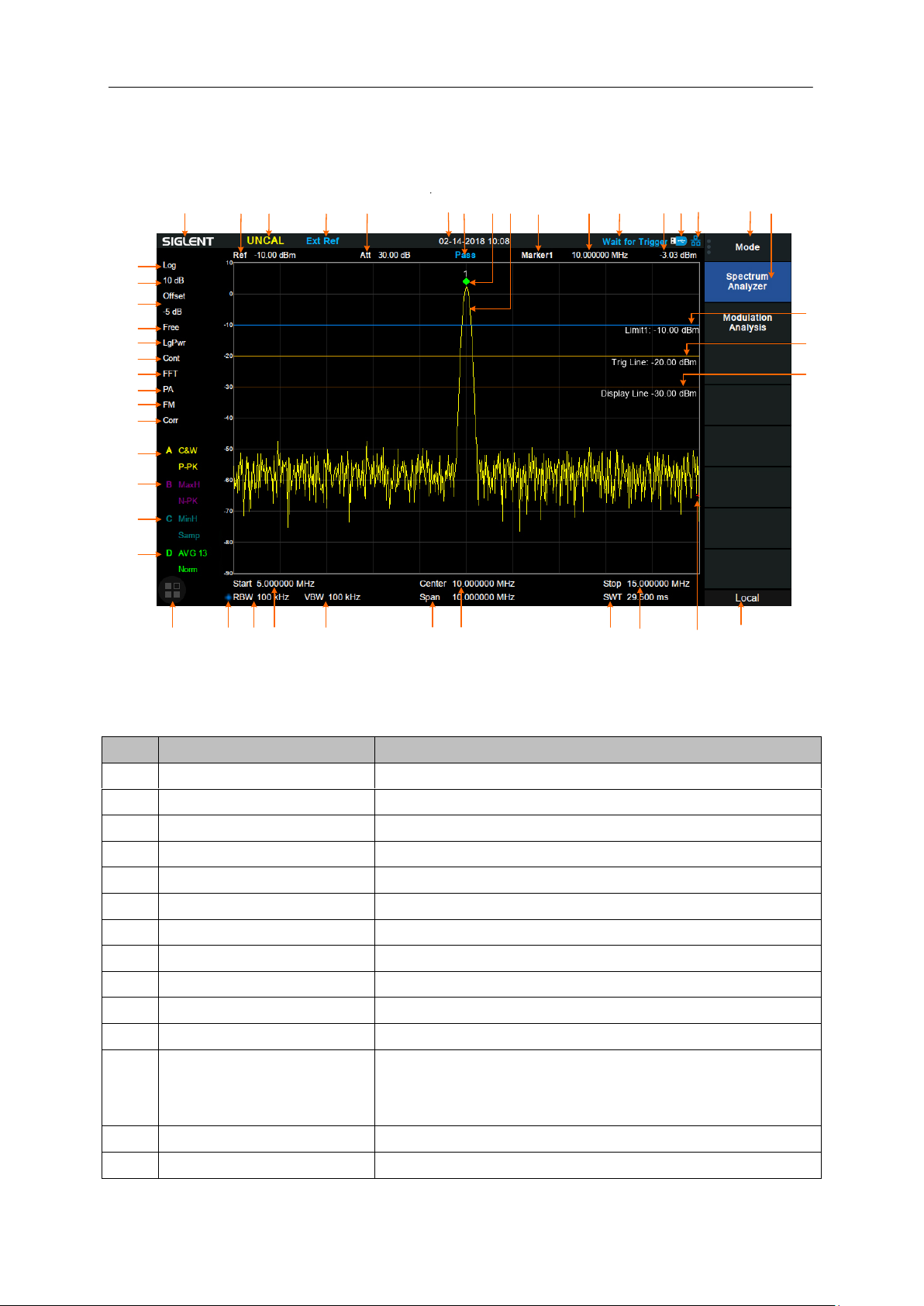
1.6 User Interface
Figure 1-12 User Interface
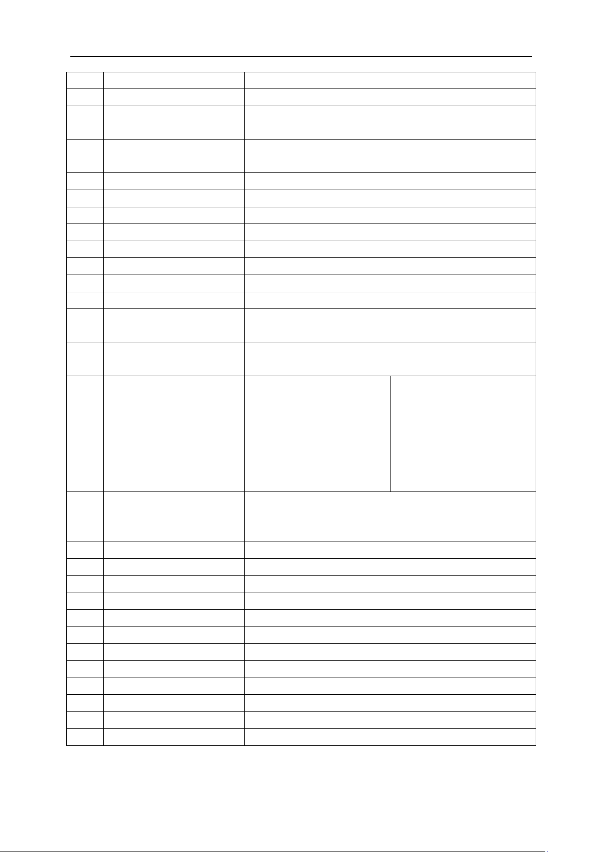
Table 1-3 User Interface labels
12 SSA3000X Plus User Manual
Page 31
SIGLENT
15
LAN identification
Displayed when a LAN cable is inserted
16
Menu title
Function of the current menu.
17
Menu items
Menu items of the current function. Front panel key menus may
be different in different modes.
18
Operation status
Local is local mode, Remote is remote mode, Upgrade
means the instrument is upgrading
19
Sweep progress
Indicates the currently scanned frequency position
20
Stop frequency
Stop frequency value
21
Sweep time
Time duration of a single sweep
22
Center frequency
Center frequency value
23
Span
Span value
24
VBW
Video bandwidth
25
Start frequency
The first frequency of a sweep
26
RBW
Resolution bandwidth
27
Manually instructions
When it appears, this parameter is not automatically coupled
but manually configured
28
Touch assistant
Click to open the commonly used functions for measurement,
such as peak search.
29
30
31
32
Trace
A\B\C\D
status
Trace type:
C&W: Clear Write
MaxH: Max Hold
MinH: Min Hold
View: View
AVG: Video average.
Detect type:
P-PK: Positive peak
N-PK: Positive peak
Samp: Sample
Norm: Normal
AVG: average
Q-PK: Quasi-peak
33
Correction
When present, indicates that there is a user-configured
amplitude correction table being mathematically applied to the
displayed trace data
34
AM or FM
AM or FM demodulation activated
35
PA
Enable or disable the Preamplifier
36
FFT
Sweep mode is FFT
37
Single or Continue
Sweep mode single or continuous
38
Average type
Log power\Power\Voltage power
39
Trigger type
Free\Video\External trigger
40
Ref offset
34:Ref offset identification;35:Ref offset value
41
Scale/Div
Scale value
42
Scale type
Logarithm or linearity
43
Limit line
Limit Pass/Fail level
44
Trigger level
Video trigger level
45
Display line
Reference display line
SSA3000X Plus User Manual 13
Page 32

SIGLENT
1.7 Firmware Operation
1.7.1 Check System Information
Users can get the system information by press System->“System Info”, including
Product Model, Serial and Host ID
Software Version and hardware Version
Option Information
1.7.2 Load Option
Refer to the procedures below to activate the options you have purchased.
1. Press System->“System Info”->“Load Option”
2. Enter the license key in the onscreen window. Press Enter to confirm your input and terminate the
license key input. Or
3. Load the .lic file provided by pressing File ->“Load” from internal memory or USB stick.
The option will be enabled after rebooting.
1.7.3 Firmware Upgrade
Follow this procedure to update the instrument firmware:
1. Download the firmware package from an official SIGLENT website, http://www.siglent.com/ens,
2. Extract and copy the .ADS file into the root directory of an USB stick.
3. Plug the USB stick into the USB Host connector. Press System->“System Info”-> “Firmware
Update”; find the .ADS file in USB stick.
4. Press the “Load”, the analyzer will perform the update process automatically.
The upgrade process will take several minutes. When the upgrade is completed, the machine will
reboot.
Any interruption during the update process will result in update failure and system data loss. This
is not covered under the warranty and the user will bear repair costs and shipping.
Do not remove the USB storage device until the update is finished.
1.8 Touch Operation
The analyzer has a 10.1 inch multi-touch screen and supports various gesture operations. Including:
Press or click on the upper-right-corner of the screen to enter the main menu;
Swipe up and down or left and right in the waveform area to change the X-axis center coordinate
or Y-axis reference level;
Perform two-points scaling in the waveform area to change the X-axis span;
14 SSA3000X Plus User Manual
Page 33
SIGLENT
Click on a screen parameter or menu for parameter selection or editing;
Open and drag the marker;
Use auxiliary shortcuts to perform common operations.
You can turn the touch screen function on and off via Display->’Touch Settings’.
1.9 Remote Control
The analyzer supports communication with computers via USB, LAN, and GPIB-USB interfaces. By
using these interfaces, in combination with programming languages and/or NI-VISA software, users
can remotely control the analyzer based on a SCPI (Standard Commands for Programmable
Instruments) compliant command set, LabView and IVI (Interchangeable Virtual Instrument), to
interoperate with other programmable instruments.
You can also remote monitor and control the analyzer in Web Browser or Easy Spectrum.
For more details, refer to the ‘Programming Guide’ or contact your nearest SIGLENT office.
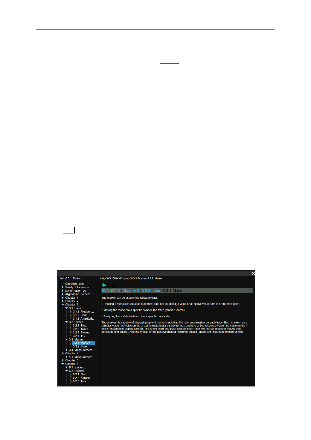
1.10 Using Built-in Help
The built-in help system provides information about every function key at the front panel and every
menu soft key.
Press Help and the embedded help would show up.
Click on the items in the contents tree on the left to navigate to any topics interested.
Click the green back or forward arrow to go back or forward to the contents just read.
Click the close sign button in the top right corner or press the Esc front-panel key to quit the help
system.
Figure 1-13 help information
SSA3000X Plus User Manual 15
Page 34
SIGLENT
1.11 Using the Security Lock
If needed, you can use the security lock (please buy it yourself) to lock the Spectrum Analyzer to a fixed
location. The method is as follows, align the lock with the lock hole and plug it into the lock hole
vertically, turn the key clockwise to lock the Spectrum Analyzer and then pull the key out.
Figure 1-14 Security Lock
16 SSA3000X Plus User Manual
Page 35

SIGLENT
Chapter 2 Spectrum Analyzer
Press Mode, select ‘Spectrum Analyzer’ to enter spectrum analyzer mode.
The ‘Spectrum Analyzer’ mode is the default mode of the machine. In this mode, the Mode backlight
does not light up; in other modes, the Mode backlight will light up.
This chapter introduces in detail the function keys and menu functions of the front panel in Spectrum
Analyzer Mode.
Subjects in this chapter:
Basic Settings
Sweep and Functions
Marker
Measurement
SSA3000X Plus User Manual 17
Page 36
SIGLENT
startstopspan
stopstartcenter
fff
)/2f(ff
span
f
Parameter
Parameter
Default
Full Span/2
Range
Zero Span, 0 Hz ~ Full Span
Nonzero Span, 50 Hz ~ (Full Span -50Hz)
Unit
GHz, MHz, kHz, Hz
Knob Step
Span > 0, step = Span/200, min 1 Hz
Span = 0, step = RBW/100, min 1 Hz
Direction Key Step
Freq Step
Related to
Start Freq, Stop Freq
2.1 Basic Settings
2.1.1 Frequency
Set the frequency-related parameters and functions of the analyzer. The sweep will restart every time
the frequency parameters are modified.
The frequency range of a channel can be expressed by three parameters: Start Frequency, Center
Frequency and Stop Frequency. If any of the parameters change, the others will be adjusted
automatically in order to ensure the coupling relationship among them:
, Where
is the span.
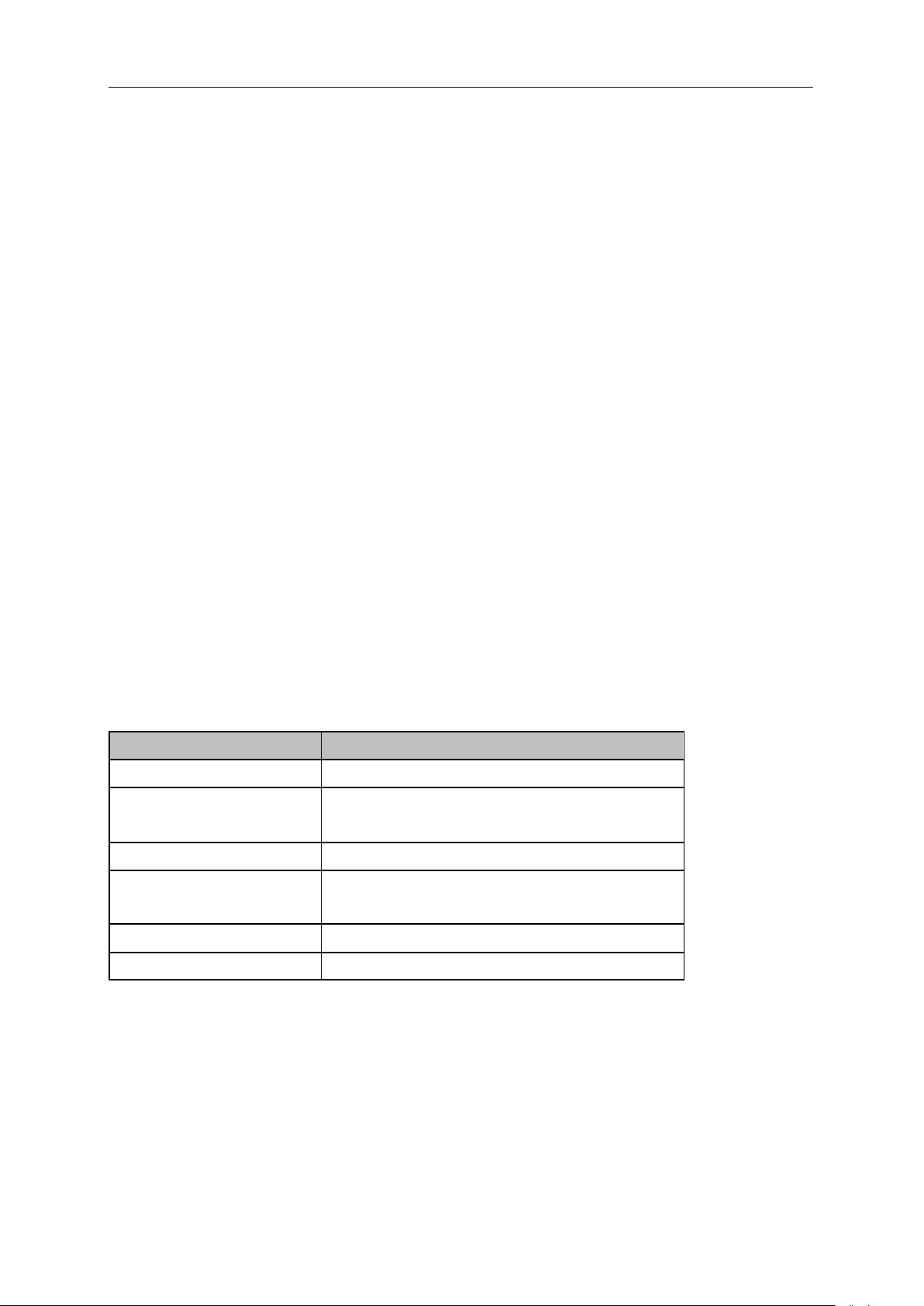
2.1.1.1 Center Frequency
Set the center frequency of the current sweep. The center frequency and span values are displayed at
the bottom of the grid respectively.
Modifying the center frequency will modify both the start frequency and stop frequency when the
span is constant (except when the start frequency or stop frequency reaches the boundary).
In Zero Span, the start frequency, stop frequency and center frequency are always the same
value.
Table 2-1 Center Frequency
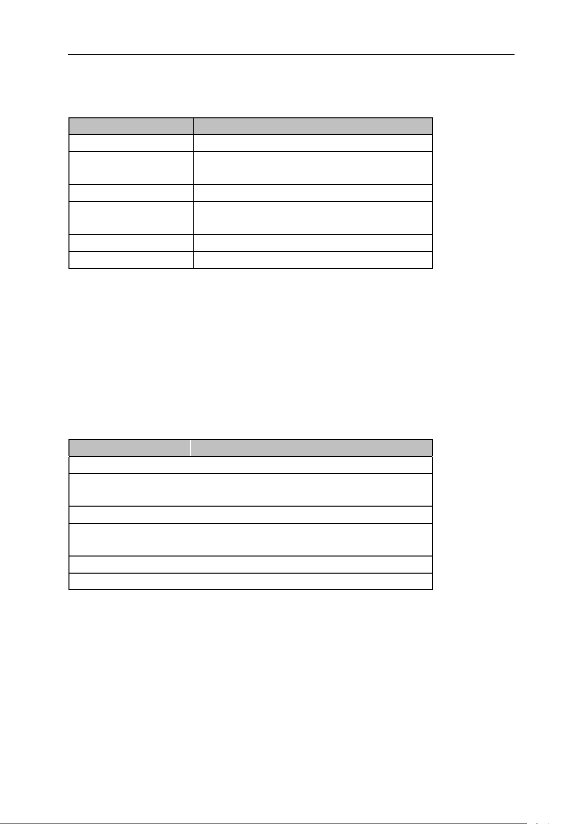
2.1.1.2 Start Frequency
Set the start frequency of the current sweep. The start and stop frequencies are displayed at the bottom
of the grid respectively.
The span and center frequency vary with the start frequency when the Span does not reach the
minimum. For more details, please refer to “Span”.
In Zero Span, the start frequency, stop frequency and center frequency are always the same
18 SSA3000X Plus User Manual
Page 37
SIGLENT
Parameter
Explanation
Default
0 Hz
Range
Zero Span, 0 Hz ~ Full Span
Nonzero Span, 0 Hz ~ (Full Span-100Hz)
Unit
GHz, MHz, kHz, Hz
Knob Step
Span > 0, step = Span/200, min 1 Hz
Span = 0, step = RBW/100, min 1 Hz
Direction Key Step
Freq Step
Related to
Center Freq, Span
Parameter
Explanation
Default
Full Span
Range
Zero Span: 0 Hz ~ Full Span
Nonzero Span: 100 Hz ~ Full Span
Unit
GHz, MHz, kHz, Hz
Knob Step
Span > 0, step = Span/200, min 1 Hz
Span = 0, step = RBW/100, min 1 Hz
Direction Key Step
Freq Step
Related to
Center Freq, Span
value.
Table 2-2 Start Frequency
2.1.1.3 Stop Frequency
Set the stop frequency of the current sweep. The start and stop frequencies are displayed at the lower
right sides of the grid respectively.
The span and center frequency vary with the stop frequency. The change of the span will affect
other system parameters. For more details, please refer to “Span”.
In Zero Span, the start frequency, stop frequency and center frequency are always the same
value.
Table 2-3 Stop Frequency
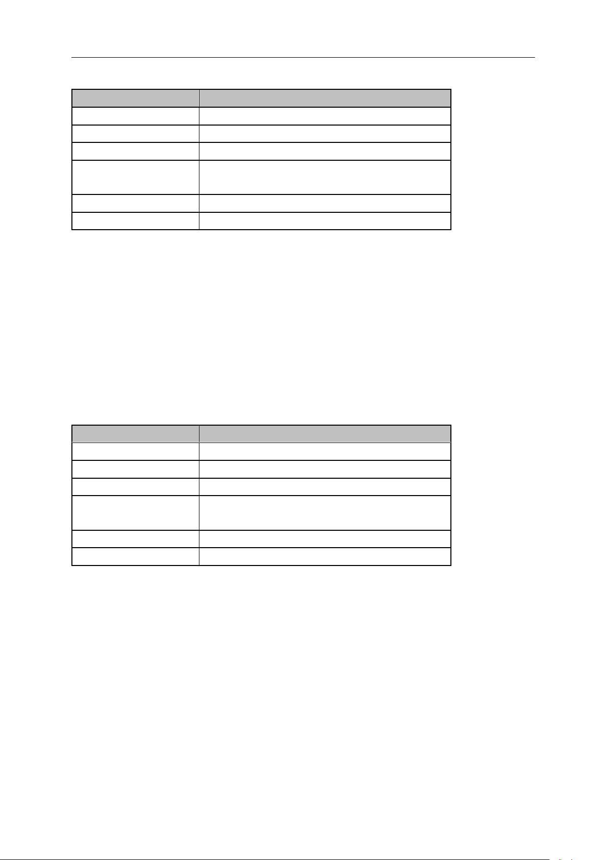
2.1.1.4 Freq Offset
Set the frequency offset value to illustrate the frequency conversion between the measured device and
the input of the spectrum analyzer.
This parameter does not affect any hardware settings of the spectrum analyzer, but only changes
the display values of center frequency, start frequency and stop frequency.
To eliminate the frequency offset value, the frequency offset value can be set to 0 Hz.
SSA3000X Plus User Manual 19
Page 38
SIGLENT
Parameter
Explanation
Default
0 Hz
Range
-100GHz ~ 100GHz
Unit
GHz, MHz, kHz, Hz
Knob Step
Span > 0, Step = Span/200, min 1 Hz
Span = 0, Step = RBW/100, min 1 Hz
Direction Key Step
Freq Step
Related to
Center Freq, Start Freq, Stop Freq
Parameter
Explanation
Default
Full Span/10
Range
1Hz ~ Full Span
Unit
GHz, MHz, kHz, Hz
Knob Step
Span > 0, Step = Span/200, min 1 Hz
Span = 0, Step = RBW/100, min 1 Hz
Direction Key Step
In 1-2-5 sequence
Related to
RBW, Span and related parameters
Table 2-4 Freq Offset
2.1.1.5 Freq Step
Setting the value of Freq Step will change the direction key step of center frequency, start frequency,
stop frequency and frequency offset.
At a fixed step change the value of the center frequency can reach the purpose of switching
measurement channels rapidly and continuously.
There are two kinds of frequency step modes:Auto and Manual. In Auto mode, the Freq step is
1/10 of the span in Non-zero span or equals the RBW while in Zero Span. In Manual mode, you
can set the step using the numeric keys.
Table 2-5 Freq Step
2.1.1.6 Signal Track
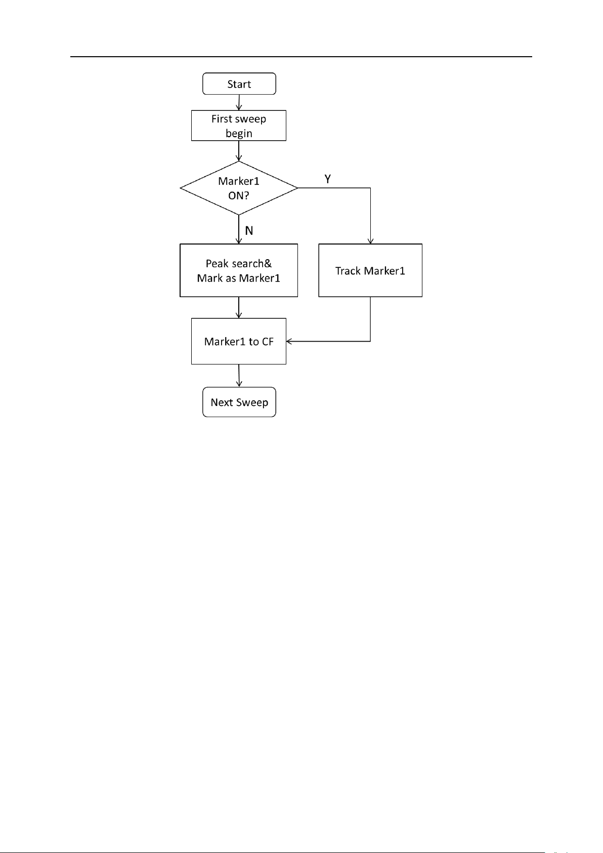
Turn on or off the signal tracking function. It is used to track the signal whose frequency is unstable and
the instantaneous change of the amplitude is less than 3 dB. By marking cursor 1 on the measured
signal, the change of the measured signal can be tracked and measured all the time.
The signal tracking process is shown in the following figure:
20 SSA3000X Plus User Manual
Page 39
SIGLENT
Figure 2-1 Signal Tracking Flow
When Marker1 is on, turn on signal tracking, a point whose amplitude does not change more than
3 dB near Marker1 will be searched and marked, and the frequency at that point will be set to
center frequency.
When Maker1 is off, turn on signal tracking, Marker1 will be activated, and a peak search will be
performed, and then the peak frequency will be set to center frequency.
Signal tracking function is only available in sweep analysis. Signal tracking function is turned off in
following cases:
Zero Span mode
Tracking Generator(TG) open
Traces are not updated, including single sweep mode or View mode.
Cont Peak function turned on
Other non-SA measurement modes
2.1.1.7 Peak -> CF
Executes a peak search and sets the center frequency (CF) of the display to the frequency of the
current peak. The function is invalid in Zero Span.
SSA3000X Plus User Manual 21
Page 40

SIGLENT
Figure 2-2 before Peak -> CF
Figure 2-3 after Peak -> CF
2.1.1.8 CF -> Step
Set the current center frequency as the Freq Step. At this point, the Freq Step will switch to “Manual”
mode automatically. This function is usually used in channel switching. For example, in harmonic
measurement, firstly locate the signal at the center frequency (CF) of the display, and then execute
22 SSA3000X Plus User Manual
Page 41
SIGLENT
Parameter
Explanation
Default
Full Span
Range
0 Hz ~ Full Span
Unit
GHz, MHz, kHz, Hz
Knob Step
Span/200, min 1 Hz
Direction Key Step
In 1-2-5 sequence
Related to
Start Freq, Stop Freq, Freq Step, RBW, Sweep time
CF->Step. Next you can press the upward direction key continuously to measure each order of
harmonic in sequence.
2.1.2 Span
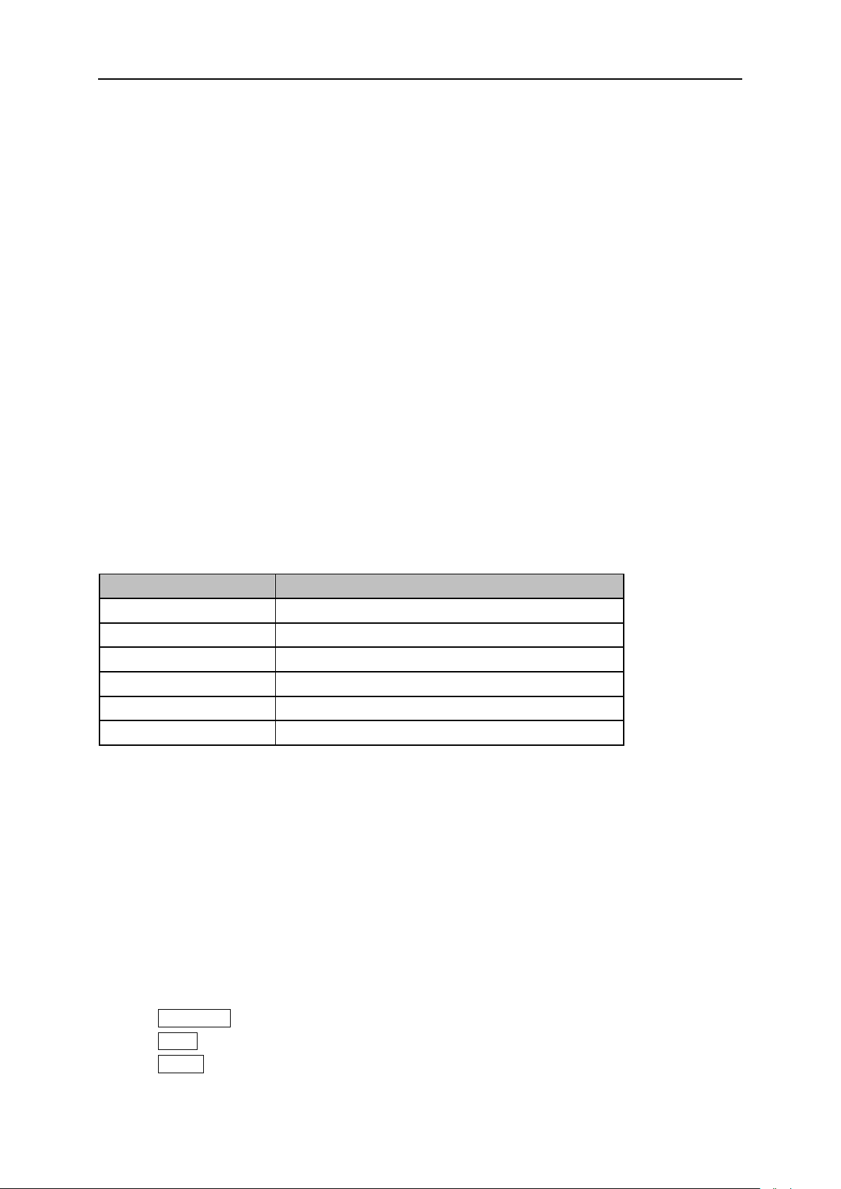
Set the span of the analyzer. Any change of this parameter will affect the frequency parameters and
restart the sweep.
2.1.2.1 Span
Set the frequency range of the current sweep. The center frequency and span are displayed at the
bottom of the grid respectively.
The start and stop frequency vary with the span when the center frequency is constant.
In non-zero span mode, the span can be set down to 100 Hz and up to the full span described in
Specifications. When the span is set to the maximum, the analyzer enters full span mode.
Modifying the span in non-zero span mode may cause an automatic change in both Freq Step and
RBW if they are in Auto mode. Besides, the change of RBW may influence VBW (in Auto VBW
mode).
Variation in the span, RBW or VBW would cause a change in the sweep time.
Table 2-6 Span
Note: 0 Hz is available only in zero span.
2.1.2.2 Full Span
Set the span of the analyzer to the maximum available frequency span.
2.1.2.3 Zero Span
Set the span of the analyzer to 0Hz. Both the start and stop frequencies will equal to center frequency
and the horizontal axis will denote time. The analyzer measures the time domain characteristics of the
amplitude of the corresponding frequency point of the input signal.
The following functions are invalid in Zero span:
Frequency: Peak->CF and Signal Track;
SPAN: Zoom In and Zoom Out;
Sweep: Sweep Mode;
SSA3000X Plus User Manual 23
Page 42
SIGLENT
Marker->: M->CF, M->CF step, M->Start Freq, M->Stop Freq, M->Span and M->CF;
Marker Fn: Read Out(default option: Time);
2.1.2.4 Zoom In
Set the span to half of its current value. At this point, the signal on the screen will be amplified to
observe signal details.
2.1.2.5 Zoom Out
Set the span to twice the current value. At this point, the signal on the screen will be reduced to gain
more information about the nearby spectrum.
2.1.2.6 Last Span
Set the span to the previous span setting.
2.1.2.7 X-Scale
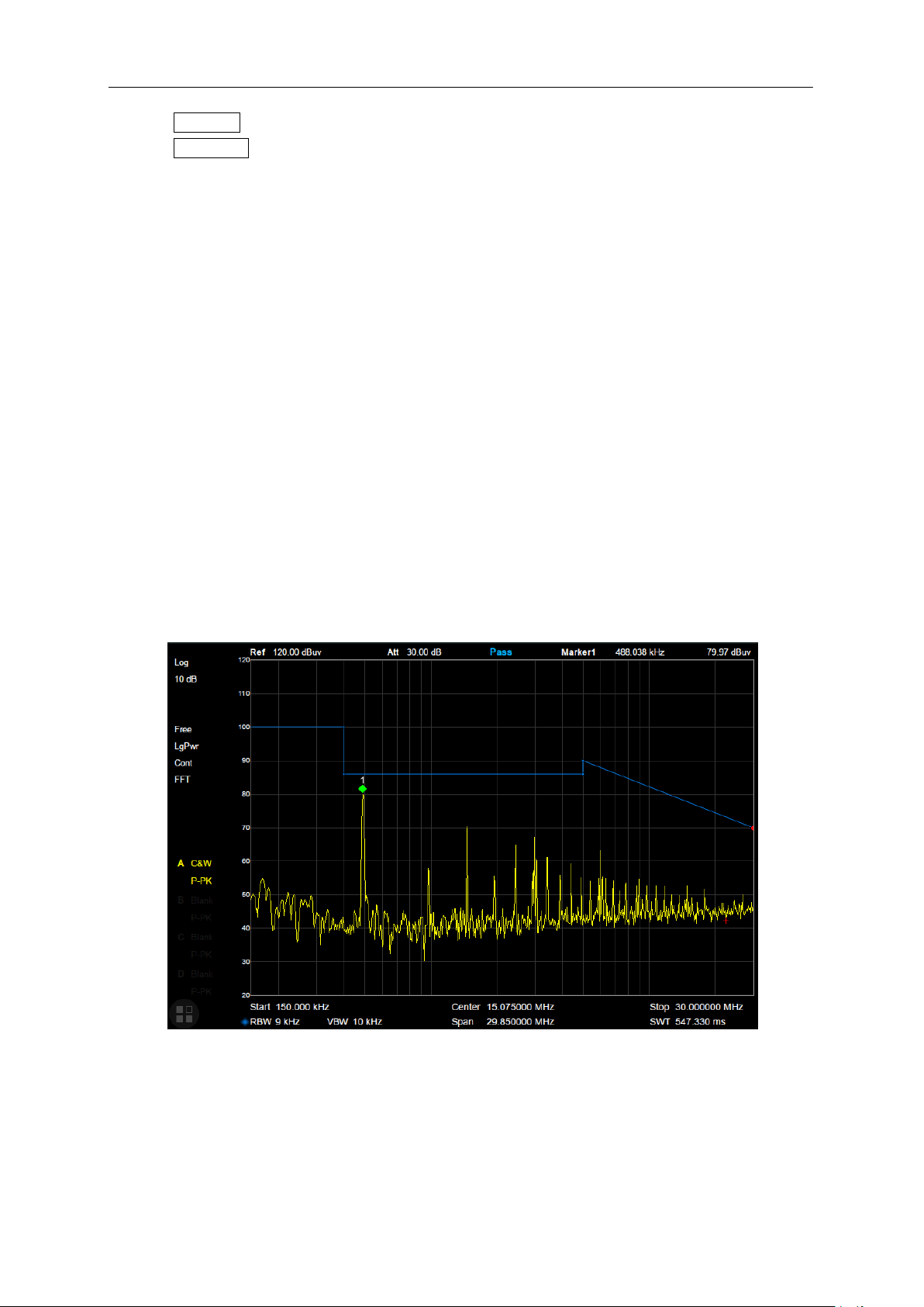
Set the scale type of X-axis to Linear (Lin) or Logarithmic (Log) scale.
In Log scale type, the frequency scale of X-axis is displayed in the logarithmic form, and Meas function
is invalid.
Figure 2-4 Logarithmic X Scale
2.1.3 Amplitude
Set the amplitude parameters of the analyzer. Through modifying these parameters, signals under
measurement can be displayed in a proper mode for easier observation and minimum error. Any
24 SSA3000X Plus User Manual
Page 43
SIGLENT
Parameter
Explanation
Default
0 dBm
Range
-200 dBm ~ 20 dBm
Unit
dBm, dBmV, dBuV, dBuA, V, W
Knob Step
In Log scale mode, step = Scale/10
In Lin scale mode, step = 0.1 dBm
Direction Key Step
In Log scale mode, step = Scale
In Lin scale mode, step = 1 dBm
Related to
Attenuator, Preamp, Ref Offset
change of Ref Level, Attenuator Value, Preamp mode and Ref Offset will restart sweep.
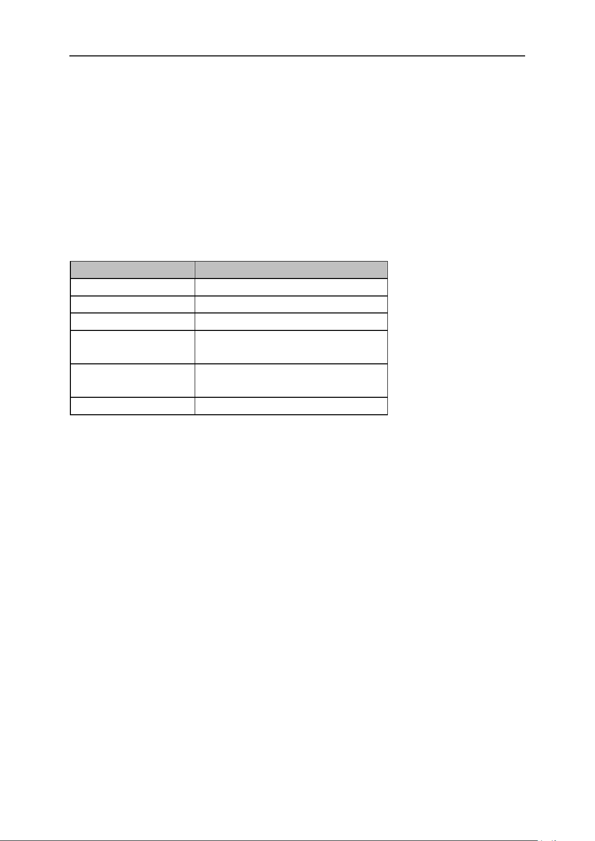
2.1.3.1 Ref Level
Set the maximum power or voltage that can be currently displayed in the trace window. The value is
displayed at the upper left corner of the screen grid.
The maximum reference (Ref) level available is affected by the maximum mixing level; input
attenuation is adjusted under a constant maximum mixing level in order to fulfill the following condition:
Ref <= ATT - PA - 20dBm, where ATT = Attenuation value, PA = Preamplifier value
Table 2-7 Ref Level
Note: the maximum reference level of different machine models may be different, please refer to the
data manual specifically.
2.1.3.2 Attenuator
Set the value for the internal attenuator of the RF input. So that the large signal can be low distortion
and the small signal can pass through the mixer with low noise.
Ref <= ATT - PA - 20dBm, where ATT = Attenuation value, PA = Preamplifier value
Input attenuation can be set up to auto or manual mode.
Auto mode: the attenuation value is automatically adjusted according to the state of preamplifier
and the current reference level.
The maximum input attenuation can be set to 31 dB. When the set parameters do not meet the
above formula, you can adjust the reference level.
SSA3000X Plus User Manual 25
Page 44
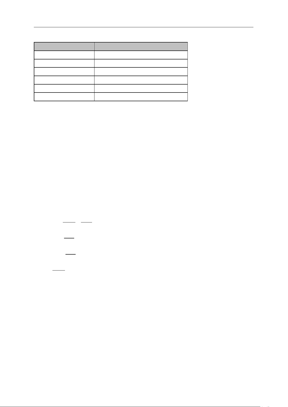
SIGLENT
Parameter
Explanation
Default
20 dB
Range
0 ~ 31 dB
Unit
dB
Knob Step
1 dB
Direction Key Step
5 dB
Related to
Preamp, Ref level
Table 2-8 Attenuator
Note: the maximum attenuator value of different machine models may be different, please refer to the
data manual specifically.
2.1.3.3 RF Preamp
Control the state of the internal preamplifier (PA) located in the RF input signal path. When the
signal-under-measurement is small, turning on the preamplifier can reduce the displayed noise level
and aid distinguishing small signals from the noise.
The corresponding icon “PA” will appear at the left side of the screen when the preamplifier is turned
on.
2.1.3.4 Units
Set the unit of the Y-axis to dBm, dBmV, dBuV, dBuA, Volts (RMS) or Watts. Default is dBm.
The conversion relationships between units are as follows.
Where, R denotes the reference impedance. The default value is 50Ω and can be adjusted by pressing
“Correction -> RF input”. The “75 Ω” impedance is just a numeric value, not a real impedance. Setting
the RF input to 75 Ω will not change the actual input impedance. A 75 Ω feed-through adapter is
required to match 75 Ω circuits to the 50 Ω input of the analyzer.
2.1.3.5 Scale
Set the logarithmic units per vertical grid division on the display. This function is only available when the
scale type is set to “log”.
By changing the scale, the displayed amplitude range is adjusted.
The Minimum range: Reference level –10 × current scale value.
The Maximum range: The reference level.
26 SSA3000X Plus User Manual
Page 45
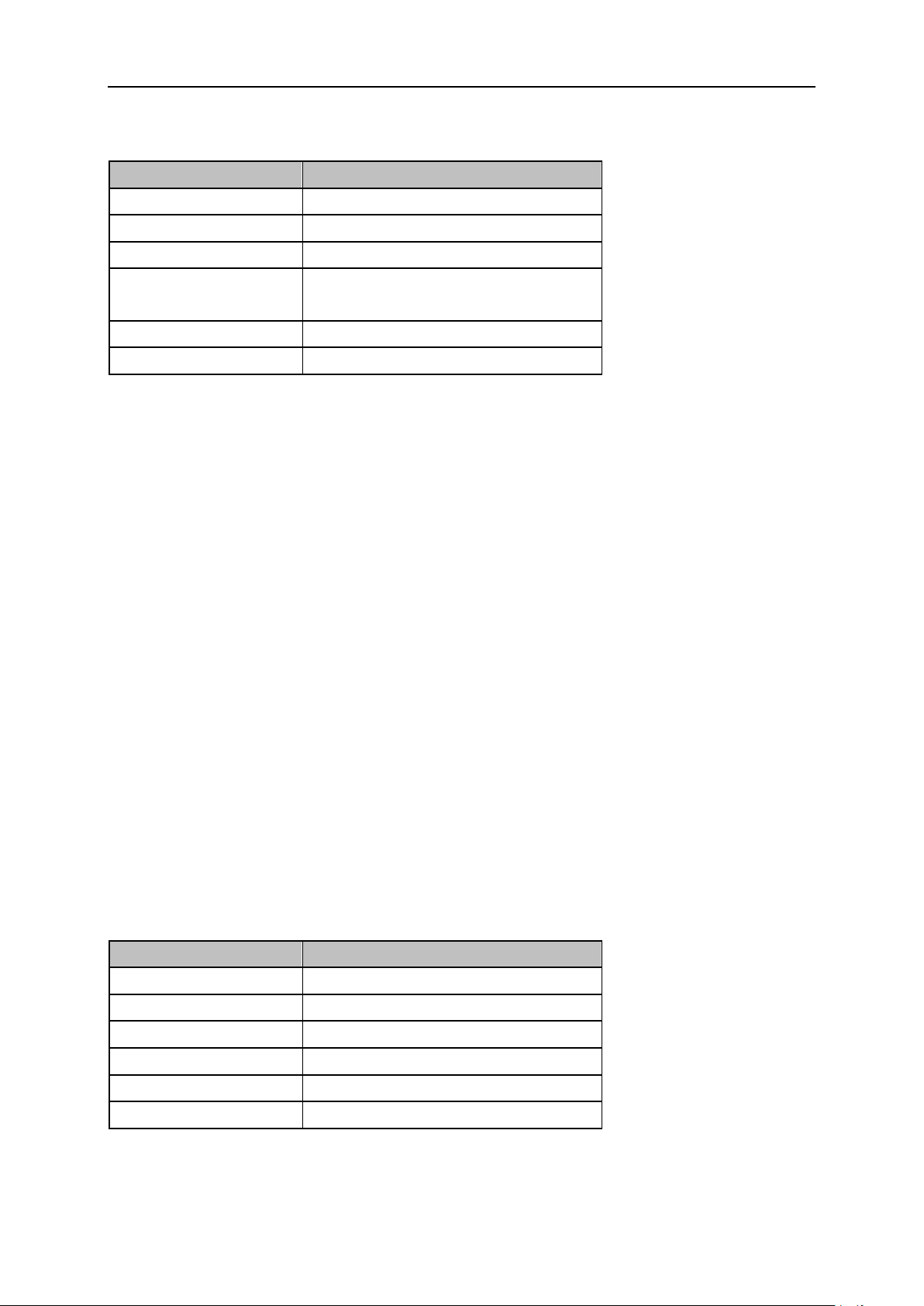
SIGLENT
Parameter
Explanation
Default
10 dB
Range
0.1 dB ~ 20 dB
Unit
dB
Knob Step
Scale>=1, 1 dB,
Scale<1, 0.1dB
Direction Key Step
1-2-5 sequence
Related to
Scale Type
Parameter
Explanation
Default
0 dB
Range
-100 dB ~ 100 dB
Unit
dB
Knob Step
Not support
Direction Key Step
Not support
Related to
Ref Level
Table 2-9 Scale/Div
2.1.3.6 Scale Type
Set the scale type of the Y-axis to Lin or Log. The default is Log.
In Lin mode, the vertical Scale value cannot be changed. The Display area is set for reference
level of 0%.
In Log scale type, the Y-axis denotes the logarithmic coordinate. The value shown at the top of the
grid is the reference level and each grid represents the scale value. The unit of Y-axis will
automatically switch to the default unit (dBm) in Log scale type when the scale type is changed
from Lin to Log.
In Lin scale type, the Y-axis denotes the liner coordinate; the values shown at the top of the grid
and the bottom of the grid are the reference level and 0 V. The scale setting function is invalid. The
unit of Y-axis will automatically switch to the default unit (Volts) in Lin scale type when the scale
type is charged from Log to Lin.
2.1.3.7 Ref Offset
Assign an offset to the reference level to compensate for gains or losses generated between the device
under measurement and the analyzer.
The change of this value changes both the reference level readout and the amplitude readout of the
marker; but does not impact the position of traces on the screen.
Table 2-10 Ref Offset
SSA3000X Plus User Manual 27
Page 46
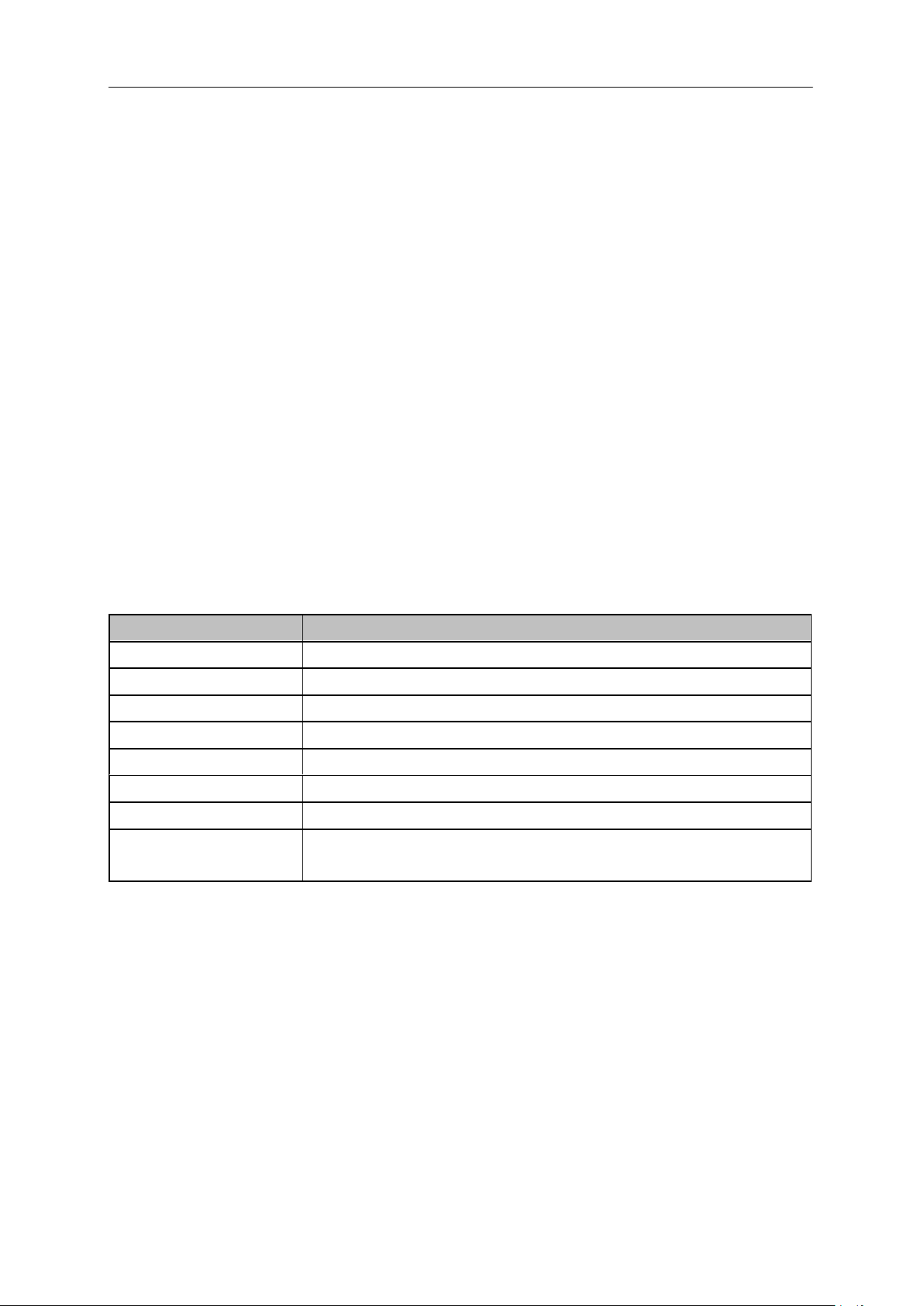
SIGLENT
Function
Explanation
Correction
Select the correction factor on or off.
Add Point
Add a point into correction table.
Point Num
Select a point to edit by point num.
Frequency
Edit the frequency value for the current selected point.
Amplitude
Edit the amplitude value for the current selected point.
Del Point
Delete the selected correction point.
Del All
Clear all data of the correction table.
Save/Load
Save or load correction data. You can save the current correction data
into or load correction data from a specified file.
2.1.3.8 Correction
Correct the displayed amplitude to compensate for gains or losses from external devices such as
antennas and cables. When using this function, you can view the correction data table and save or load
the current correction data. When amplitude correction is enabled, both the trace and related
measurement results will be mathematically corrected. Positive correction values are added to the
measured values. Negative (-) correction values are subtracted from the measured values.
1. RF Input
Set the input impedance for numeric voltage-to-power conversions. To measure a 75 Ω device, you
should use a 75 Ω to 50 Ω adapters to connect the analyzer with the system-under-test and then set the
input impedance to 75 Ω.
2. Apply Correction
Enable or disable amplitude corrections. Default is Off. The analyzer provides four correction factors
that can be created and edited separately, but they can be applied independently in any combination.
3. Edit Correction factors
Table 2-11 Edit Correction table
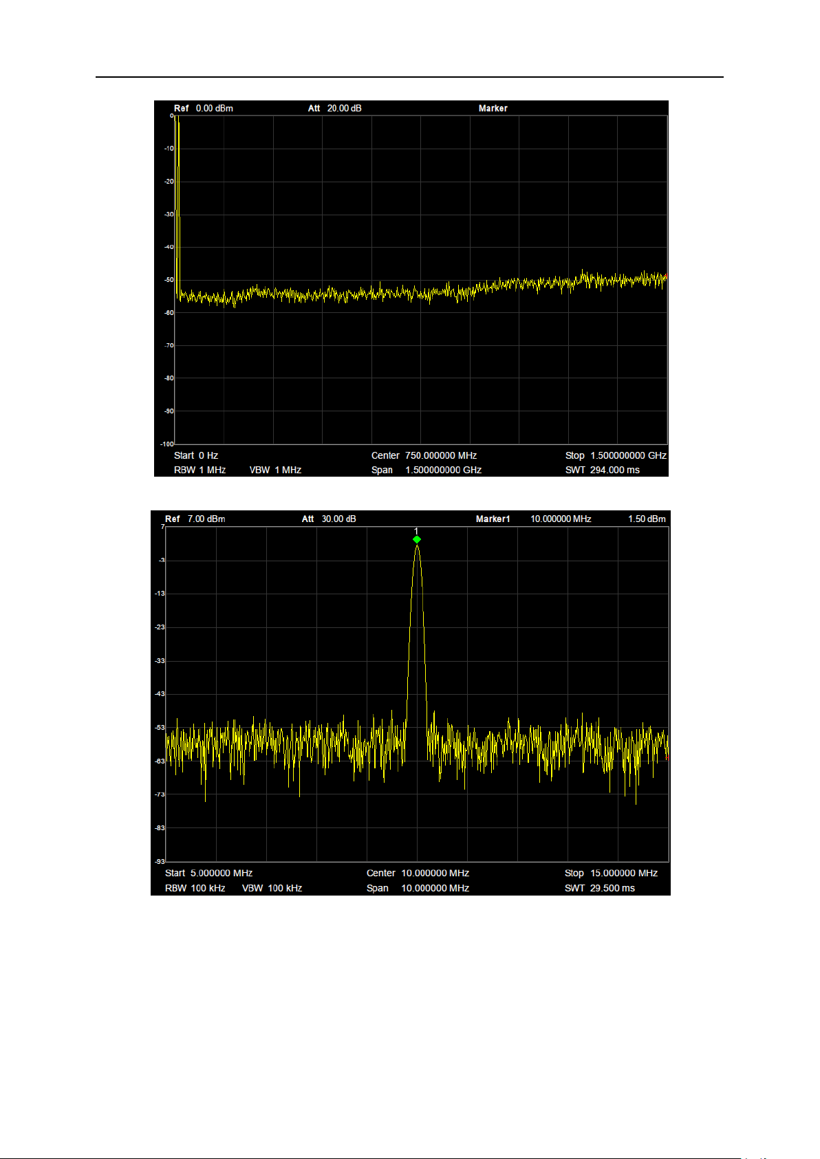
2.1.4 Auto Tune
The analyzer will search for signals automatically throughout the full frequency range and adjust the
frequency and amplitude settings for optimum display of the strongest signal.
In the process of auto search, The “Auto Tune” is shown in the status bar on the screen until the
search is finished.
Some parameters such as the reference level, scale, input attenuation and maximum mixing level
may be changed during the auto search.
28 SSA3000X Plus User Manual
Page 47
SIGLENT
Figure 2-5 before Auto Tune
Figure 2-6 after Auto Tune
SSA3000X Plus User Manual 29
Page 48
SIGLENT
Parameter
Explanation
Default
1 MHz
Range
1 Hz ~ 1 MHz
Unit
MHz, kHz, Hz
Knob Step
in 1, 3, 10 sequence
Direction Key Step
in 1, 3, 10 sequence
Relation
Span, VBW, V/R Ratio, Sweep Time
2.2 Sweep and Functions
2.2.1 BW
The bandwidth menu contains the RBW (Resolution Bandwidth), VBW (Video Bandwidth), average
type and filter type. Filter type includes the EMI filter type that enables EMI measurement controls.
2.2.1.1 Resolution Bandwidth
Set the resolution bandwidth in order to distinguish between signals which have frequency components
that are near one another.
Reducing the RBW will increase the frequency resolution, but will also increase the sweep time
dramaticlly (Sweep Time is affected by a combination of RBW and VBW when the analyzer is in
Auto mode).
Genrerally, the frequency resolution ability is affected by RBW, RBW Filter shape factor, LO Phase
noise, and LO Residual FM.
RBW varies with the span (non-zero span) in Auto RBW mode.
Under EMI filter, RBW can only be set to 200 Hz, 9 kHz, 120 kHz and 1 MHz with a 6dB shape
factor.
Table 2-12 RBW
Notes: RBW of above table is in Gauss filter type.
2.2.1.2 Video Bandwidth
Set the video bandwidth in order to filter out the noise outside the video band.
Reducing the VBW will smooth the trace and helps to highlight small signals from noise, but it will
also increase the sweep time (Sweep Time is affected by a combination of RBW and VBW when it
is in Auto mode).
VBW varies with RBW when it is in Auto mode. While in Manual mode, VBW is not affected by
RBW.
30 SSA3000X Plus User Manual
Page 49
SIGLENT
Parameter
Explanation
Default
1 MHz
Range
1 Hz ~ 1 MHz
Unit
MHz, kHz, Hz
Knob Step
in 1, 3 sequence
Direction Key Step
in 1, 3 sequence
Relation
RBW, V/R Ratio, Sweep Time
Parameter
Explanation
Default
1
Range
0.001 ~ 1000
Unit
N/A
Knob Step
in 1, 3 sequence
Direction Key Step
in 1, 3 sequence
Relation
RBW, VBW
Table 2-13 VBW
2.2.1.3 V/R Ratio
Set the ratio of VBW to RBW. This value is different while measuring different kinds of signals:
Sine/Continuous Wave (CW) signals: Use 1 to 3 (for faster sweeps)
Pulsed/transient signals: Use 10 (to reduce the influence on the amplitude of transient signals)
Noise signals: Generally use 0.1 (to obtain the average of noises)
Table 2-14 V/R Ratio
2.2.1.4 Average Type
Choose one of the following averaging types: log power (video), power (RMS), or voltage averaging.
When trace average is on, the average type is shown on the left side of the display.
1. Log Power
Select the logarithmic (decibel) scale for all filtering and averaging processes. This scale is "Video"
because it is the most common display and analysis scale for the video signal within analyzer. This
scale is excellent for finding Sine/CW signals near noise.
2. Power Average
In this average type, all filtering and averaging processes work on the power (the square of the
magnitude) of the signal, instead of its log or envelope voltage. This scale is best for real-time power
measurement of complex signals.
3. Voltage Average
In this Average type, all filtering and averaging processes work on the voltage of the envelope of the
SSA3000X Plus User Manual 31
Page 50
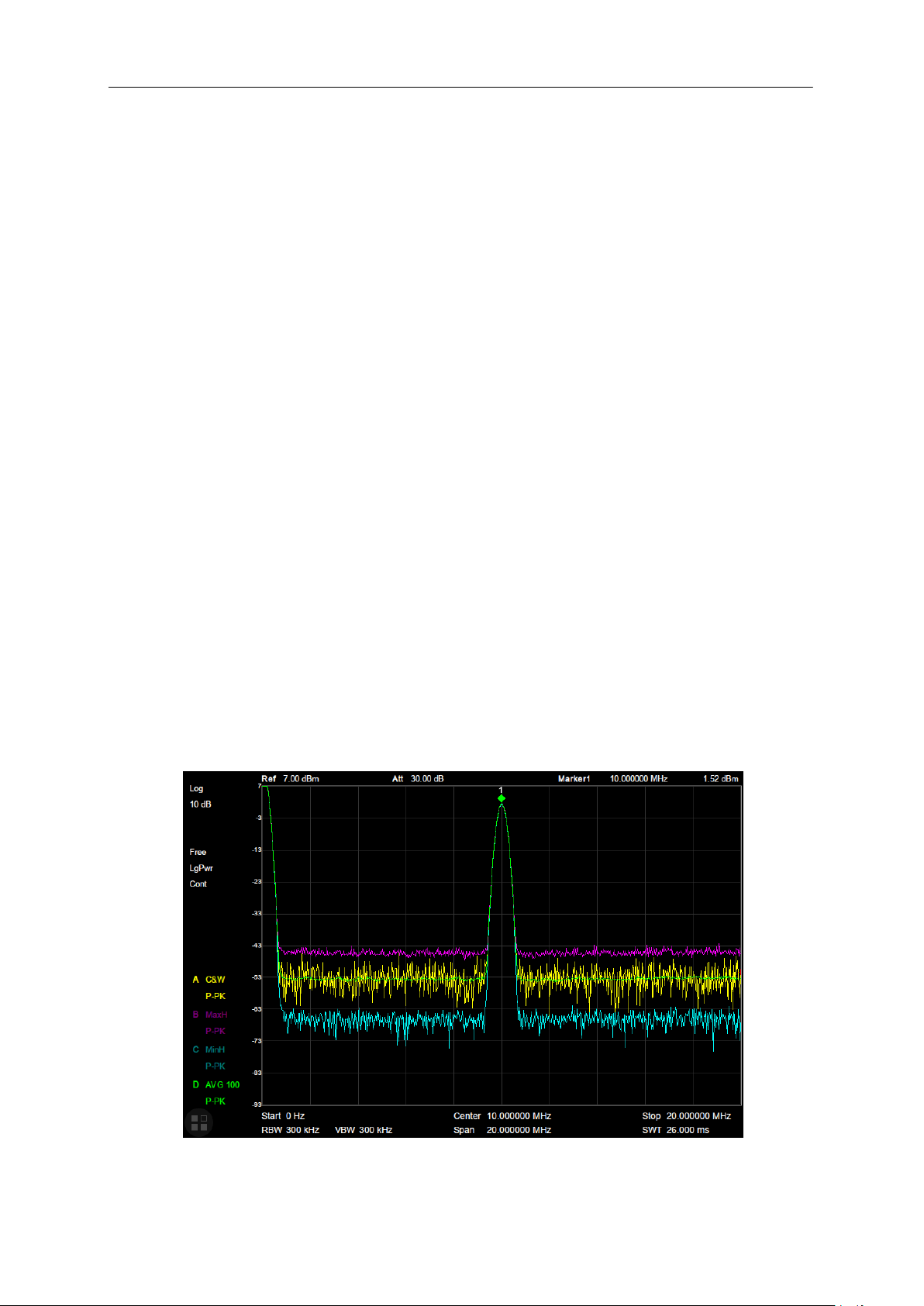
SIGLENT
signal. This scale is suitable for observing rise and fall behavior of AM or pulse-modulated signals such
as radar and TDMA transmitters.
2.2.1.5 Filter
Set the RBW filter type. The analyzer supports two kinds of RBW filters: “Gauss” (-3 dB bandwidth) and
“EMI” (-6 dB bandwidth).
When “EMI” is selected, resolution bandwidth can only be 200 Hz, 9 kHz, 120 kHz and 1 MHz
“Quasi-Peak” detector is available only when “EMI” filter is turned on.
2.2.2 Trace
The sweep signal is displayed as a trace on the screen.
2.2.2.1 Select Trace
The analyzer allows for up to four traces to be displayed at the same time. Each trace has its own color
(Trace A - Yellow, Trace B - Purple, Trace C - Light blue and Trace D - Green). All traces can be set
parameter independently. As a default, analyzer will choose Trace A and set the type of the trace as
Clear Write.
2.2.2.2 Trace Type
Set the type of the current trace or disable it. The system calculates the sampled data using a specific
operation method according to the trace type selected and displays the result. Trace types include
Clear Write, Max Hold, Min Hold, View, Average and Blank. The corresponding icon of the trace type
will be displayed in the status bar at the left of the screen, as shown in the figure below.
32 SSA3000X Plus User Manual
Figure 2-7 Trace Type
Page 51
SIGLENT
Parameter
Explanation
Default
100
Range
1 ~ 999
Unit
N/A
Knob Step
1
Direction Key Step
5
1. Clear Write
Erases any data previously stored in the selected trace, and display the data sampled in real-time of
each point on the trace.
2. Max Hold
Retain the maximum level for each point of the selected trace. Update the data if a new maximum level
is detected in successive sweeps. Max Hold is very effective when measuring events that may take
successive scans to measure accurately. Some common applications include FM Deviation, AM NRSC,
and frequency hopping or drift.
3. Min Hold
Display the minimum value from multiple sweeps for each point of the trace and update the data if a
new minimum is generated in successive sweeps.
4. View
Freezes and holds the amplitude data of the selected trace. The trace data is not updated as the
analyzer sweeps.
5. Blank
Disable the trace display and all measurements of this trace.
6. Average
Set the averages times of the selected trace.
More averages can reduce the noise and the influence of other random signals; thus highlighting the
stable signal characteristics. The larger the averages times is, the smoother the trace will be. Enabling
averaging will take more time to collect the full spectral information because the analyzer needs to
sweep the set average count. The displayed data is averaged in a first-in-first-out fashion.
Table 2-15 Average Times
2.2.2.3 Math
Set the computational method of the math trace.
1. Output Z
The Math result is denoted by the Z variable and can be displayed by trace A, B, C, or D.
SSA3000X Plus User Manual 33
Page 52
SIGLENT
Parameter
Explanation
Default
0 dB
Range
-100 dB ~ 100 dB
Unit
dB
Knob Step
1 dB
Direction Key Step
1 dB
2. Input X, Y
Input X, Y can be applied to trace A, B, C, or D.
3. Calculation Type
The analyzer provides the calculation types as shown below:
Power Diff: X-Y+Offset→Z
Power Sum: X+Y+Offset→Z
Log Offset: X+ Offset→Z
Log Diff: X-Y-Ref→Z
4. Offset value
Table 2-16 Offset value
2.2.3 Detect
The analyzer displays the sweep signal on the screen in the form of a trace. For each trace point, the
analyzer always captures all the data within a specific time interval and processes (Peak, Average, etc.)
the data using the detector currently selected, then it displays the processed data (a single data point)
on the screen.
Select an appropriate detector type according to the actual application in order to ensure the accuracy
of the measurement.
The available types are Pos Peak, Neg Peak, Sample, Normal, Average and Quasi Peak. The
default is Pos peak.
1. Positive Peak
For each trace point, Positive Peak detector displays the maximum value of data sampled within the
corresponding time interval.
2. Negative Peak
For each trace point, Negative Peak detector displays the minimum value of data sampled within the
corresponding time interval.
3. Sample
For each trace point, Sample detector displays the transient level corresponding to the central time
34 SSA3000X Plus User Manual
Page 53
SIGLENT
Parameter
Explanation
Default
N/A
Range
900 us ~ 1.5 ks (Quasi Peak: 900us ~ 15ks)
Unit
ks, s, ms, us
Knob Step
Sweep time/100, min =1 ms
Direction Key Step
in 1, 3 sequence
point of the corresponding time interval. This detector type is applicable to noise or noise-like signal.
4. Normal
Normal detector (also called ROSENFELL Detector) displays the maximum value and the minimum
value of the sample data segment in turn: Odd-numbered data points display the maximum value and
even-numbered data points display the minimum value. In this way, the amplitude variation range of the
signal is clearly shown.
5. Average
For each trace point, Average detector displays the average value of data sampled within the
corresponding time interval.
6. Quasi-Peak
Quasi-Peak (QP) detector, which is a weighted form of peak detector, is used for EMC pulse testing.
The QP detector is designed to follow CISPR-16 response specifications. For a single frequency point,
the detector detects the peaks within the QP dwell time.
The peaks detected are weighted using a digital model that follows a defined response curve as well as
the time constant specified in the CISPR 16 standards. The measurement time for QP is far longer than
Peak Detector.
2.2.4 Sweep
Sets parameters about the Sweep functions, including sweep time, sweep times, sweep mode, etc.
2.2.4.1 Sweep Time
Sets the time needed for the analyzer to finish a sweep within the span range. The sweep time can be
set in “Auto” or “Manual” mode and the default is “Auto”.
In non-zero span, the analyzer selects the shortest sweep time on the basis of the current RBW
and VBW settings if Auto is selected.
Decreasing the sweep time will decrease measurement time. However, an error may be caused if
the specified sweep time is less than the minimum sweep time in Auto coupling; at this point,
“UNCAL” is shown in the status bar on the screen. Measurements taken with “UNCAL” showing
may not meet the specifications of the instrument and can have significant error.
Table 2-17 Sweep Time
SSA3000X Plus User Manual 35
Page 54
SIGLENT
Parameter
Explanation
Default
1
Range
1 ~ 99999
Unit
N/A
Knob Step
1
Direction Key Step
1
2.2.4.2 Sweep Rule
The analyzer provides two sweep time rules to meet the different sweep time requirements:
Speed: Activates the default fast sweep time rule.
Accuracy: Activates the normal sweep time rule to ensure increased measurement accuracy.
The Speed sweep time rule provides a fast measurement function that decreases the sweep time.
While the Accuracy Sweep rule will increase the measurement accuracy.
2.2.4.3 Sweep
Set the sweep mode in single or continuous, the default is continuous. The corresponding icon of the
sweep will be displayed in the status bar at the left of the screen.
1. Single
Set the sweep mode to “Single”. The number on the parameter icon denotes the current sweep times.
2. Numbers
Set the sweeps times for a single sweep. In single sweep mode, the system executes the specified
sweeps times and the number shown on the icon in the status bar at the left of the screen varies with
the process of the sweep.
3. Continue
Set the sweep mode to “Continue”. The character Cont on the parameter icon denotes the analyzer is
sweeping continuously.
If the instrument is in single sweep mode and no measurement function is enabled, press this key
and the system will enter continuous sweep mode and sweep continuously if the trigger conditions
are satisfied.
If the instrument is in single sweep mode and a measurement function is on, press this key and the
system will enter continuous sweep mode and measure continuously if the trigger conditions are
satisfied.
In continuous sweep mode, the system will send a trigger initialization signal automatically and
enter the trigger condition judgment directly after each sweep.
Table 2-18 Sweep Times
36 SSA3000X Plus User Manual
Page 55
SIGLENT
Parameter
Explanation
Default
50 ms
Range
0 s ~ 10 s
Unit
ks, s, ms, us
Knob Step
1 ms
Direction Key Step
1 ms
2.2.4.4 Sweep Mode
Sweep mode includes auto mode, sweep mode and FFT mode.
1. Auto
When the sweep mode is auto, the analyzer selects the sweep mode automatically between Sweep
and FFT Mode in the shortest time.
2. Sweep
True swept operation including point-by-point scanning. The Sweep mode is available when the RBW
is in 30 Hz – 1 MHz.
3. FFT
The FFT mode is only available when RBW is in 1 Hz - 10 kHz.
When the tracking generator (TG) is on, the sweep mode is forced to Sweep.
2.2.4.5 QPD Dwell Time
Dwell time is the measurement time at a single frequency. QP detector gets its weighted envelope
response during this dwell time. The longer dwell time is, the more sufficiently the QP detector
responses to a single frequency, and the more accurate the QP detector envelope is.
Table 2-19 QPD Dwell Times
2.2.5 Trigger
The trigger type can be Free Run, Video or External.
2.2.5.1 Free Run
The trigger conditions are satisfied at any time and the analyzer generates trigger signals continuously.
2.2.5.2 Video Trigger
A trigger signal will be generated when the system detects a video signal of which the voltage exceeds
the specified video trigger level.
Set the trigger level with the video trigger menu entry. At this point, the trigger level line (Trig Line) and
SSA3000X Plus User Manual 37
Page 56
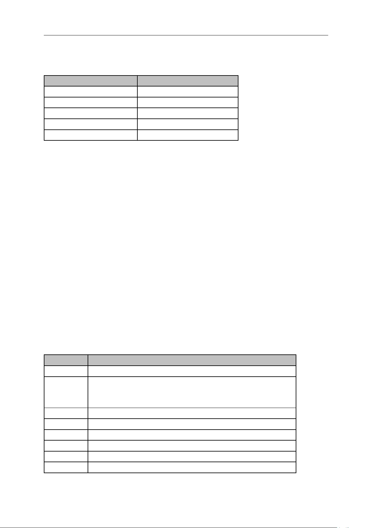
SIGLENT
Parameter
Explanation
Default
0 dBm
Range
-300 dBm ~ 50 dBm
Unit
dBm
Knob Step
1 dBm
Direction Key Step
10 dBm
Function
Explanation
Type
Select upper or lower limit type. The default value is Upper.
Mode
Select limit line or limit point. The default value is Line.
Set the number of the point to be edited if you selected the point type, and
the range is 1 ~ 100.
Add point
Add a new point for editing.
X-axis
Edit the X-axis value (frequency or time) of the current point.
Amplitude
Edit the amplitude of the current point or line.
Del Point
Delete the point whose number is selected in Mode.
Del All
Delete all the points.
Save/Load
Save or load the limit file.
value are displayed on the screen.
Table 2-20 Trigger Setup
2.2.5.3 External
In this mode, an external signal (TTL signal) is input from the [TRIGGER IN] connector at the rear panel
and trigger signals are generated when this signal fulfills the specified trigger edge condition.
Set the trigger edge in external trigger to the rising (Pos) or falling (Neg) edge of the pulse.
2.2.6 Limit
The analyzer supports Pass/Fail test function. In this function, the measured curve will be compared
with the pre-edited curve. If the related rules are met, the result is “Pass”, else the result is “Fail”.
2.2.6.1 Limit1
Enable or disable limit1.
2.2.6.2 Limit1 Edit
Edit the properties of limit1.
Table 2-21 Limit1 Edit Menu
38 SSA3000X Plus User Manual
Page 57
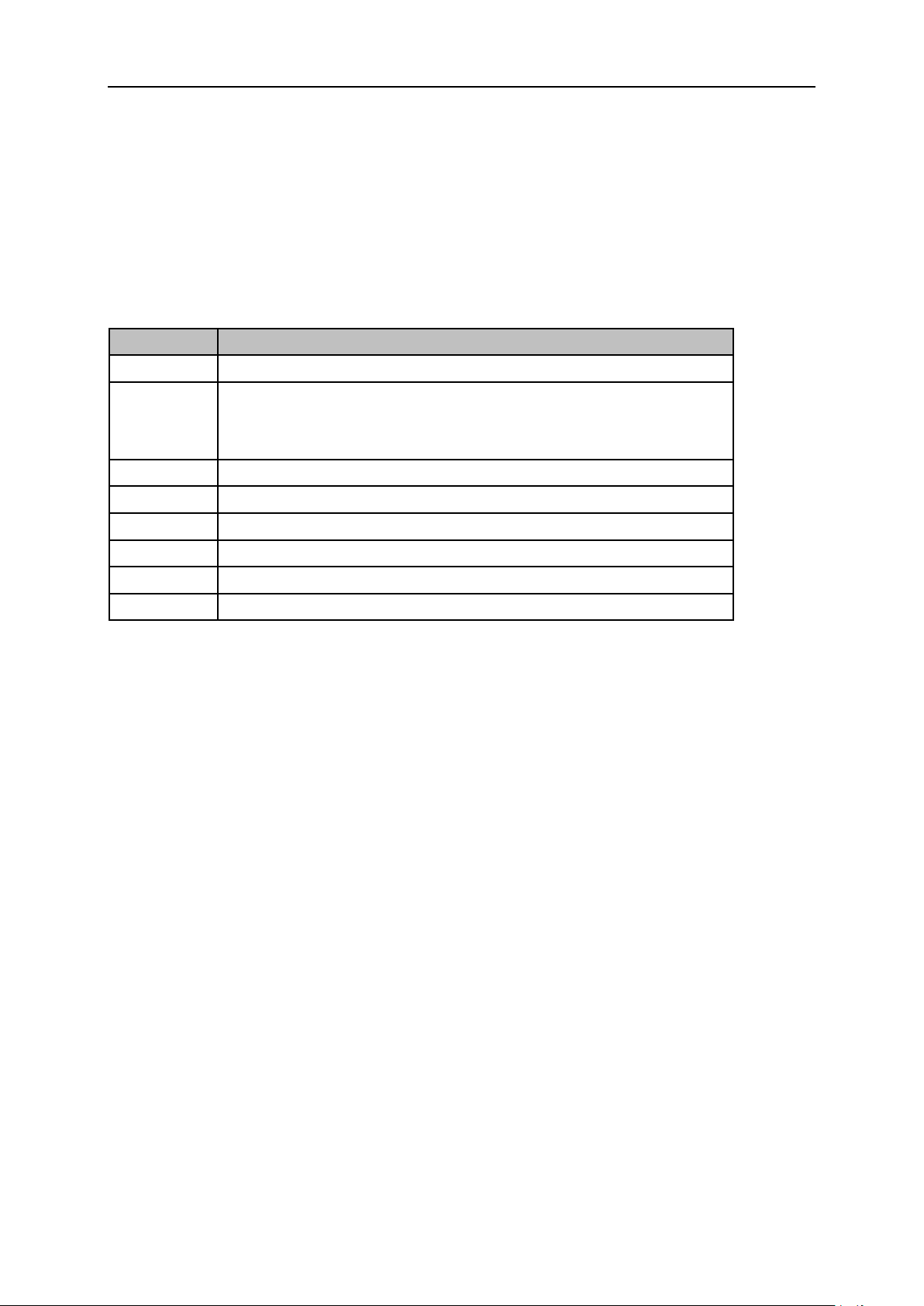
2.2.6.3 Limit2
Function
Explanation
Type
Select upper or lower limit type. The default value is Lower.
Mode
Select limit line or limit point. The default value is Line.
Set the number of the point to be edited if you selected the point type, and
the range is 1 ~ 100.
Add point
Add a new point for editing.
X-axis
Edit the X-axis value (frequency or time) of the current point.
Amplitude
Edit the amplitude of the current point or line.
Del Point
Delete the point whose number is selected in Mode.
Del All
Delete all points.
Save/Load
Save or load the limit file.
Enable or disable limit2.
2.2.6.4 Limit2 Edit
Edit the properties of limit2.
Table 2-22 Limit2 Edit Menu
SIGLENT
2.2.6.5 Test
Enable or disable the limit test function.
2.2.6.6 Setup
1. Fail to stop
Turn on or off the Fail to stop function. If the function is on, the analyzer will stop sweep and retain the
test result when the test result is “Fail”.
2. Buzzer
Turn on or off the buzzer. When the buzzer is on, it beeps when the test result is “Fail”.
3. X Axis
Set the X-axis to frequency or time domain. The default value is Freq.
Note that all the points of the current limit line will be deleted if the X-axis unit changes.
2.2.7 TG (Tracking Generator)
Set the parameters related to the tracking generator (TG) and normalize.
SSA3000X Plus User Manual 39
Page 58
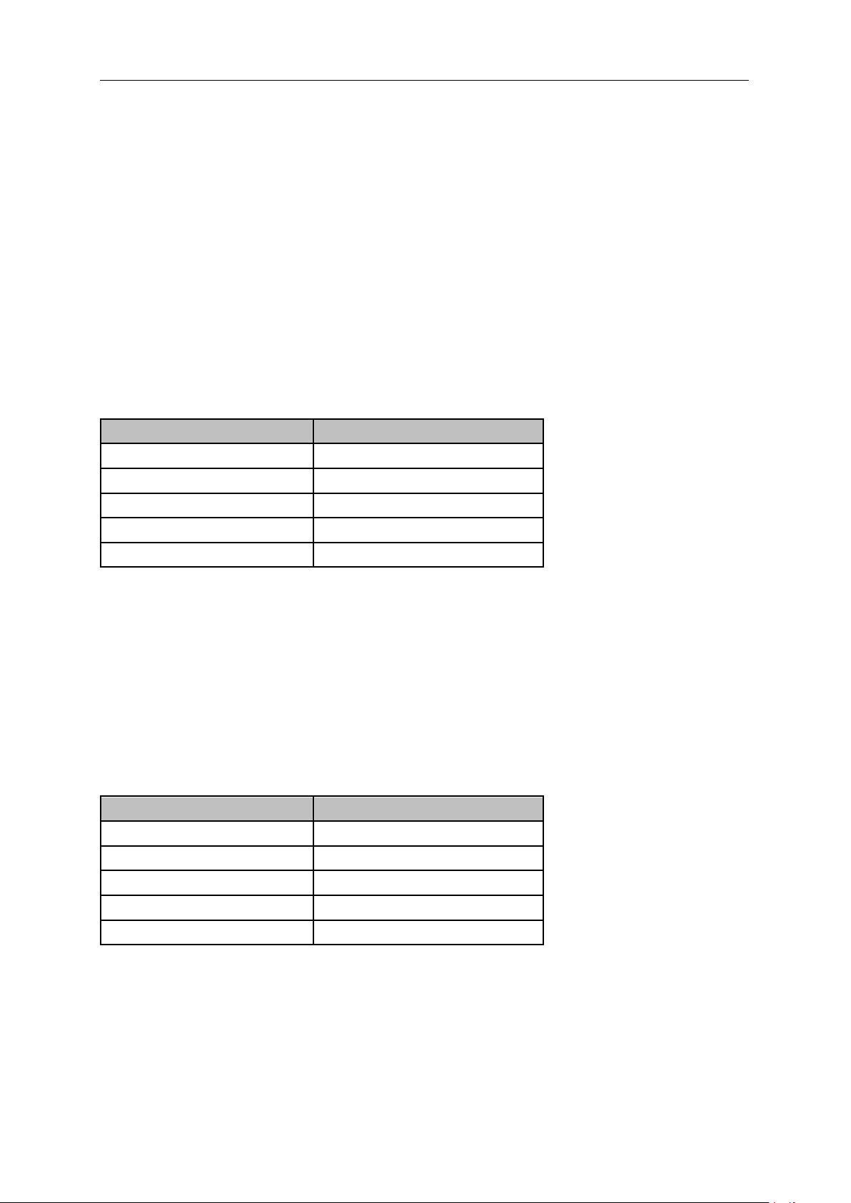
SIGLENT
Parameter
Explanation
Default
-20 dBm
Range
-20 dBm ~ 0 dBm
Unit
dBm
Knob Step
1 dBm
Direction Key Step
10 dBm
Parameter
Explanation
Default
0 dB
Range
-200 dB ~ 200 dB
Unit
dB
Knob Step
1 dB
Direction Key Step
10 dB
2.2.7.1 TG
The tracking generator is a signal source with an adjustable frequency and amplitude. When the TG is
enabled, a signal with the same frequency of the current sweep signal will be output from the [TG
SOURCE] connector at the front panel. The power of the signal could be set through the menu. The TG
output frequency follows the analyzer sweep frequency. For example, if the sweep is set to scan from 1
MHz to 10 MHz, the TG output frequency will change from 1 MHz to 10 MHz in coordinated steps with
the sweep. In Zero Span mode, the TG frequency will match the center frequency of the analyzer.
2.2.7.2 TG Level
Set the output power of the signal of the tracking generator.
Table 2-23 TG Level
2.2.7.3 TG Level Offset
Assigns a certain offset to the output power of the TG when gains or losses occur between the TG
output and external device in order to display the actual power value.
This parameter only changes the readout of the TG output power, rather than the actual value.
The offset could be either a positive (gain in the external output) or a negative (loss in the external
output).
Table 2-24 TG Level Offset
2.2.7.4 Normalize
Normalization can eliminate errors in the TG Level. Before using this function, connect the [TG
SOURCE] output terminal of the TG with the [RF INPUT] input terminal of the analyzer.
The reference trace can be stored by pressing the “Store Ref” button after the current sweep finished.
Then the normalize function can be enabled. When normalization is enabled, the corresponding value
40 SSA3000X Plus User Manual
Page 59
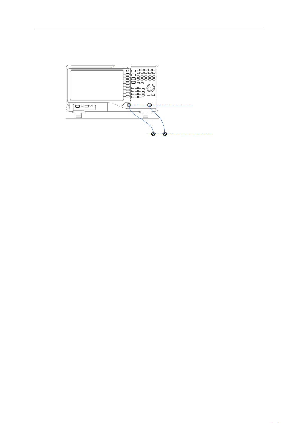
of the reference trace will be subtracted from the trace data after every sweep.
Default
reference plane
Normalized
reference plane
The reference trace must be stored before the normalize function can be used.
Figure 2-8 Normalize
2.2.7.5 Store Ref
SIGLENT
Before enable the normalize function, you should press the “Store Ref” button to store the data of Trace
A to Trace D. Then Trace D is the reference trace.
The tracking generator needs to be turned on first, and the reference trace can be saved only
when the first screen is scanned.
The normalization can be enabled only after the reference trace is stored.
After you stored the reference trace and enabled the normalization, if then you change some
parameters which will change the sweep frequency and sweep time, the "UNCAL" sign will be
displayed in the upper left corner of the screen, indicating that the reference trace is no longer
applicable to the new trace, and prompting you to save the reference trace again.
2.2.7.6 Ref Trace
Set whether to display the reference trace or not. If “View” is selected, the reference trace saved (Trace
D) will be shown in “View” type.
Note: When normalization is enabled, the unit of Y-axis is “dB” and will not be influenced by the
definition in AMPT->Units. At this point, “(dB)” is displayed under the Y-axis scale in the user interface.
2.2.7.7 Norm Ref Level
Adjust the vertical position of the trace on the screen by adjusting the reference level when
normalization is enabled.
This operation differs from the Ref Level function in the AMPT menu. This parameter has no influence
on the reference level of the analyzer.
SSA3000X Plus User Manual 41
Page 60
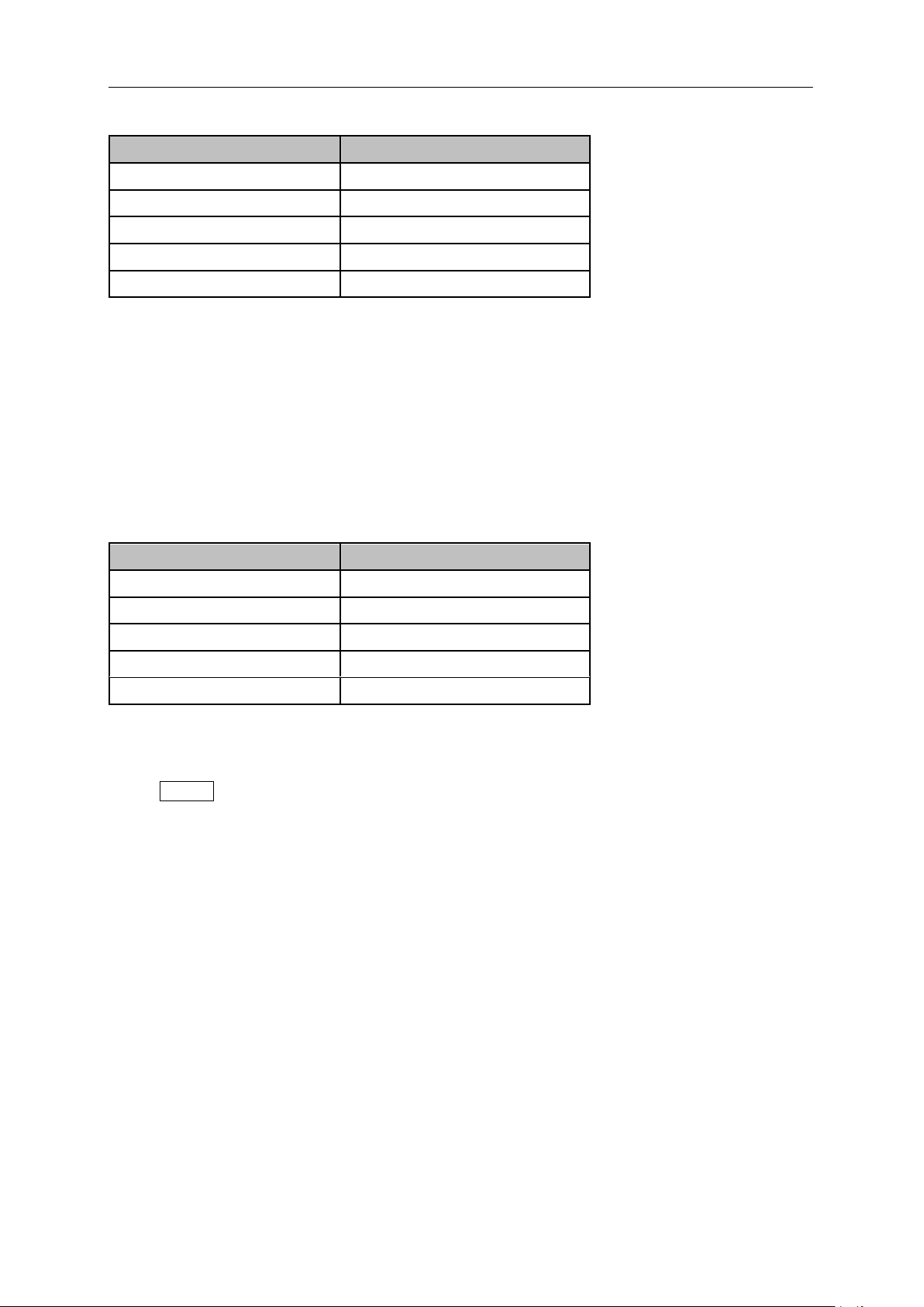
SIGLENT
Parameter
Explanation
Default
0 dB
Range
-200 dB ~ 200 dB
Unit
dB
Knob Step
1 dB
Direction Key Step
10 dB
Parameter
Explanation
Default
100%
Range
0 ~ 100%
Unit
100%
Knob Step
1%
Direction Key Step
10%
Table 2-25 Reference level under normalization
2.2.7.8 Norm Ref Pos
Adjust the vertical position of the normalization reference level on the screen by adjusting the reference
position when normalization is enabled.
The function of this menu is similar to that of Norm Ref Level. When it is set to 0%, the
normalization reference level is displayed at the bottom of the screen grid and at the top when it is
set to 100%.
Table 2-26 TG reference position under normalization
2.2.8 Demod
Press Demod at the front panel to enter the demodulation setting menu. Both AM and FM
demodulations are available on the analyzer.
2.2.8.1 Demod (AM/FM)
Set the demodulation type to AM or FM or off. The default is off.
The analyzer features an earphone jack and the demodulated signal can be output in audio
frequency (AF) mode through the earphone. The frequency and intensity of AF denotes the
frequency and amplitude of the signal respectively.
A marker would be enabled automatically, place it at the desired frequency and set a demod time.
The analyzer would demod at the marker frequency for the demod time, and then performs a
normal sweep.
Zero span and linear scale type amplitude can be used to see the time domain waveform of the
modulated signal.
More demodulation analysis, please refer to AM/FM modulation analyzer in MA option.
42 SSA3000X Plus User Manual
Page 61
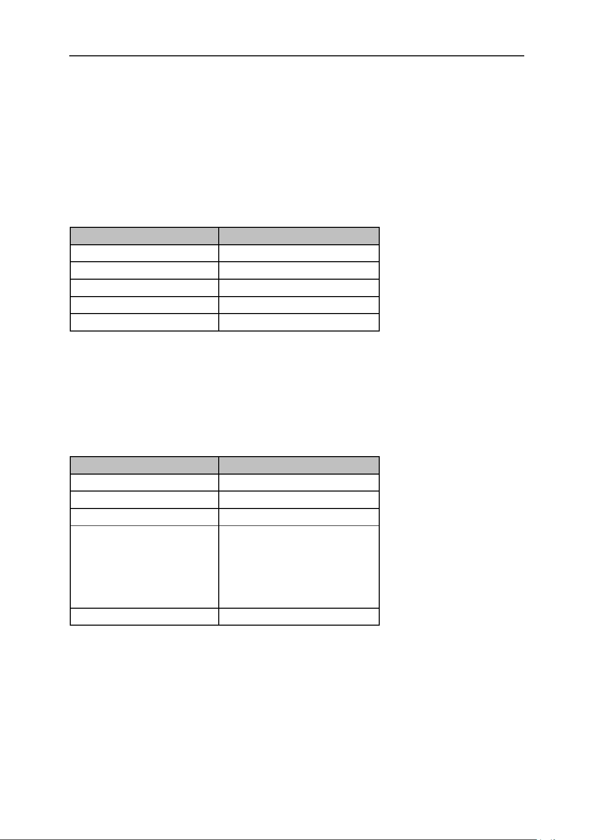
SIGLENT
Parameter
Explanation
Default
6
Range
0 ~ 10
Unit
N/A
Knob Step
1
Direction Key Step
1
Parameter
Explanation
Default
5 s
Range
5 ms ~ 1000 s
Unit
ks, s, ms, us
Knob Step
0 ms ~ 100 ms, step = 1 ms
100 ms ~ 1 s, step = 10 ms
1 s ~ 10 s, step = 100 ms
10 s ~ 100 s, step = 1 s
100 s ~ 1000 s, step = 10 s
Direction Key Step
In 1-2-5 step sequence
2.2.8.2 Earphone
Set the status of the earphone. When it is on, the demodulated signal can be heard through the
earphone during the demodulation. By default, it is off.
2.2.8.3 Volume
Set the volume of the earphone.
Table 2-27 Volume
2.2.8.4 Demod Time
Set the time for the analyzer to complete a signal demodulation after each sweep.
If the Earphone is set to “On”, you will hear the demodulated signal through the earphone during the
demodulation. A longer demod dwell time is recommended for demodulating audio signals.
Table 2-28 Demod time
SSA3000X Plus User Manual 43
Page 62
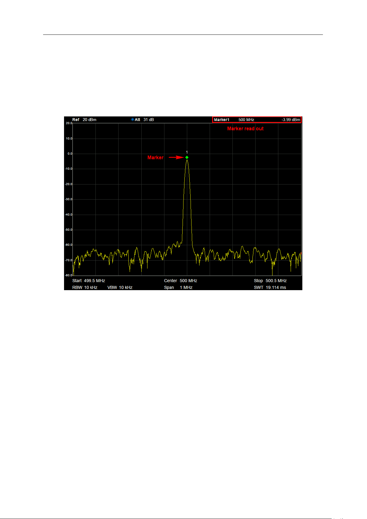
SIGLENT
2.3 Marker
2.3.1 Marker
The marker appears as a rhombic sign (as shown below) for identifying points on a trace. You can
easily read the amplitude, frequency and sweep time of the marked point on the trace.
Figure 2-9 Marker
The analyzer allows for up to eight/four pairs of markers to be displayed at one time, but only one
pair or a single marker is active every time.
You can use the numeric keys, knob or direction keys to modify the desired frequency or time as
well as view the readouts of different points on the trace.
2.3.1.1 Select Marker
Select one of the eight markers. The default is Marker1. When a marker is selected, you can set its type,
trace to be marked, readout type and other related parameters. The enabled marker will appear on the
trace selected through the Select Trace option and the readouts of this marker are also displayed in
the active function area and at the upper right corner of the screen.
44 SSA3000X Plus User Manual
Page 63
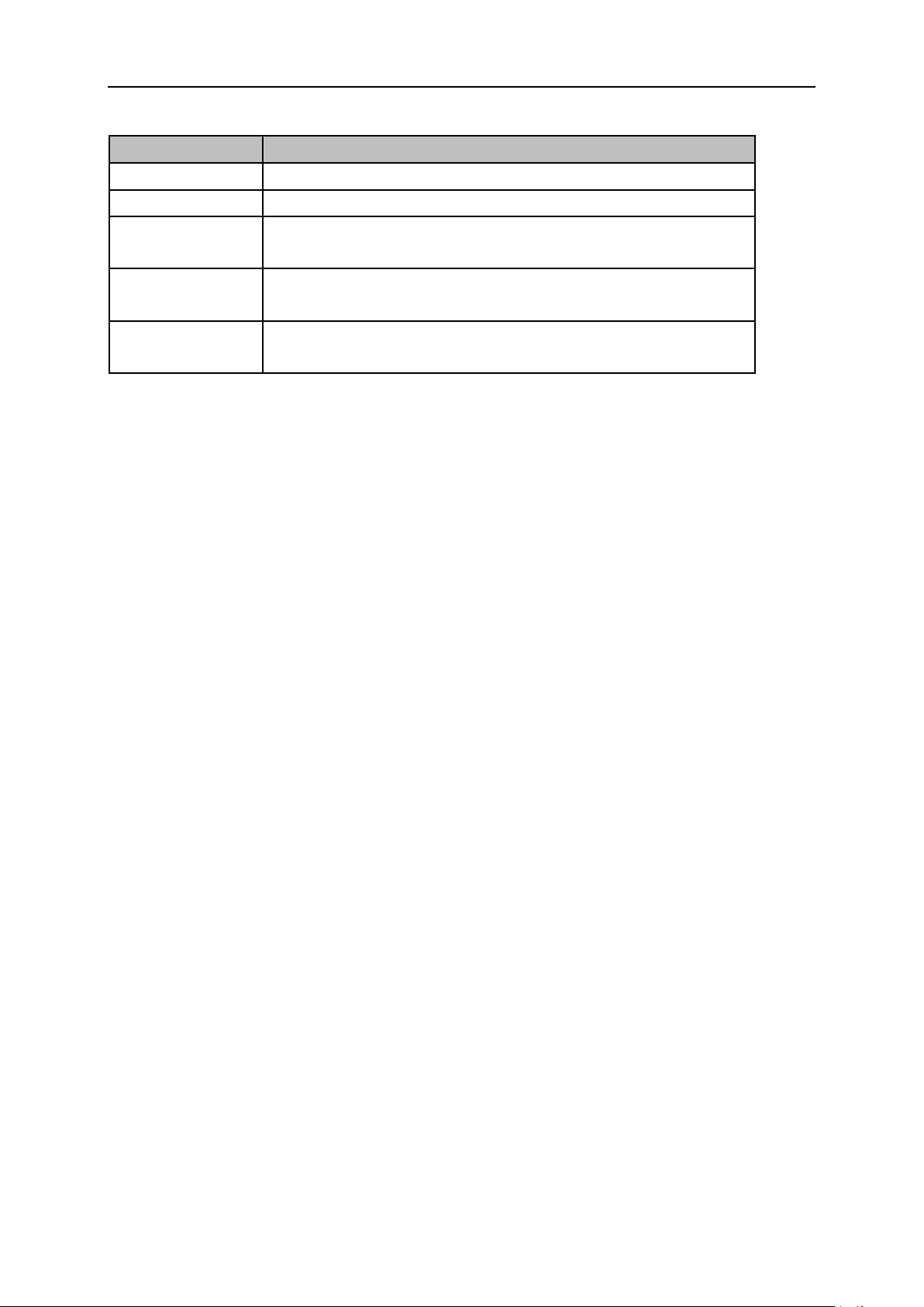
Table 2-29 Marker parameters
Parameter
Explanation
Default
Center Frequency
Range
0 ~ Full Span
Unit
Readout = Frequency: GHz, MHz, kHz, Hz
Readout = Time or Period: s, ms, us, ns, ps
Knob Step
Readout = Frequency, Step = Span/(Sweep Points - 1)
Readout = Time or Period, Step = Sweep Time/(Sweep Points - 1)
Direction Key Step
Readout = Frequency, Step = Span/10
Readout = Time or Period, Step = Sweep Time/10
2.3.1.2 Select Trace
Select the trace to be marked by the current marker. Valid selections include A, B, C, or D.
2.3.1.3 Normal
SIGLENT
One of the marker types. It is used to measure the X (Frequency or Time) and Y (Amplitude) values of a
certain point on the trace. When selected, a marker with the number of the current marker (such as “1”)
appears on the trace.
If no active marker exists currently, a marker will be enabled automatically at the center frequency
of the current trace.
You can use the numeric keys, knob or direction keys to move the marker. The readouts of the
marker will be displayed at the upper right corner of the screen.
The readout resolution of the X-axis (frequency or time) is related to the span. For higher readout
resolution, reduce the span.
2.3.1.4 Delta
One of the marker types. It is used to measure the delta values of X (Frequency or Time) and Y
(Amplitude) between the reference point and a certain point on the trace. When selected, a pair of
markers appears on the trace: Fixed Related Marker (marked by a combination of the marker number
and letter “+”, such as “2+”) and the Delta Marker (marked by the “∆”, such as “1∆2”).
After the marker selects “Delta”, the original marker will become the delta measurement marker,
and the related marker of the incrementing sequence number will become the reference “fixed”
marker
The delta marker is in the "relative to" state, and its X-axis position can be changed; the related
marker is in the "fixed" state by default (the X-axis and Y-axis positions are fixed), but the X-axis
can be adjusted by changing to the "normal" state.
The first row in the upper right corner of the trace area shows the frequency (or time) difference
and amplitude difference between the two markers; the second row in the upper right corner of the
trace area shows the X axis and amplitude value of the related marker.
SSA3000X Plus User Manual 45
Page 64
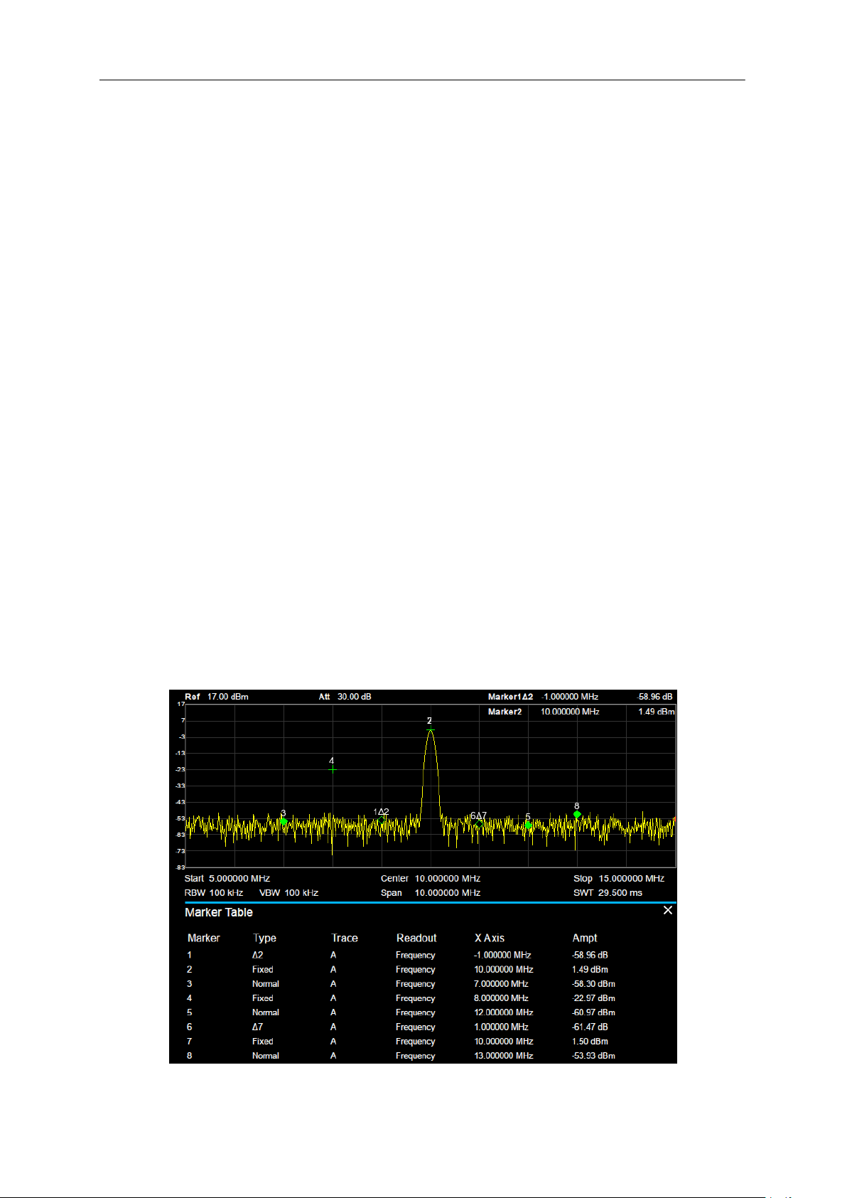
SIGLENT
2.3.1.5 Fixed
One of the marker types. When “Fixed” is selected, the X-axis and Y-axis of the marker will not change
by the trace and can only be changed through the menu. The fixed marker is marked with "+".
After the marker selects “Delta”, the original marker will become the delta measurement marker, and
the related marker of the incrementing sequence number will become the reference “fixed” marker
2.3.1.6 Off
Turn off the marker currently selected. The marker information displayed on the screen and functions
based on the marker will also be turned off.
2.3.1.7 Relative To
“Relative to” is used to measure the delta values of X (Frequency or Time) and Y (Amplitude) between
two markers which can mark on different traces.
After the marker selects “Delta”, the original marker will become the delta measurement marker, and
the related marker of the incrementing sequence number will become the reference “fixed” marker
2.3.1.8 Marker Table
Enable or disable the Marker Table.
Display all the markers enabled on the lower portion of the screen, including marker number, trace
number, marker readout type, X-axis readout and amplitude. Through this table you can view the
measurement values of multiple points. The table allows for up to eight markers to be displayed at one
time.
46 SSA3000X Plus User Manual
Figure 2-10 Marker table
Page 65

SIGLENT
2.3.2 Marker ->
1. M->CF
Set the center frequency of the analyzer to the frequency of the current marker.
If the Normal marker is selected, the center frequency will be set to the frequency of the current
marker.
If the Delta or Delta Pair marker is selected, the center frequency will be set to the frequency of
the Delta Marker.
The function is invalid in Zero span.
2. M -> CF Step
Set the center frequency step of the analyzer to the frequency of the current marker.
If the Normal marker is selected, the center frequency step will be set to the frequency of the
current marker.
If the Delta or Delta Pair marker is selected, the center frequency step will be set to the frequency
of the Delta Marker.
The function is invalid in Zero span.
3. M -> Start Freq
Set the start frequency of the analyzer to the frequency of the current marker.
If the Normal marker is selected, the start frequency will be set to the frequency of the current
marker.
If the Delta or Delta Pair marker is selected, the start frequency will be set to the frequency of the
Delta Marker.
The function is invalid in Zero span.
4. M -> Stop Freq
Set the stop frequency of the analyzer to the frequency of the current marker.
If the Normal marker is selected, the stop frequency will be set to the frequency of the current
marker.
If the Delta or Delta Pair marker is selected, the stop frequency will be set to the frequency of the
Delta Marker.
The function is invalid in Zero span.
5. M ->Ref Level
Set the reference level of the analyzer to the amplitude of the current marker.
If the Normal marker is selected, the reference level will be set to the amplitude of the current
marker.
If the Delta or Delta Pair marker is selected, the reference level will be set to the amplitude of the
Delta Marker.
6. ΔM->Span
Set the span of the analyzer to the frequency difference between the two markers in Delta marker type.
If the Normal marker is selected, this function is invalid.
SSA3000X Plus User Manual 47
Page 66

SIGLENT
The function is invalid in Zero span.
7. ΔM->CF
Set the center frequency of the analyzer to the frequency difference between the two markers in Delta
marker type.
If the Normal marker is selected, this function is invalid.
The function is invalid in Zero span.
2.3.3 Marker Fn
Special marker functions including Noise Marker, N dB BW and Freq Counter.
2.3.3.1 Select Marker
Select one of the eight markers (1, 2, 3, 4, 5, 6, 7 and 8) and the default is Marker1.
2.3.3.2 Noise Marker
Execute the Noise marker function for the selected marker and read the normalized noise power
spectral density.
If the current marker is “Off” in the Marker menu, pressing Noise Marker will first set it to Normal
type automatically; then measure the average noise level at the marked point and normalize this
value to 1 Hz bandwidth. During this process, certain compensation is always made on the basis
of the detection and trace types. The measurement will be more precise if RMS Avg or Sample
detection type is used.
This function can be used for measuring the C/N ratio.
2.3.3.3 N dB BW
Enable the N dB BW measurement or set the value of N dB. The N dB BW denotes the frequency
difference between two points that are located on both sides of the current marker and with N dB fall
(N<0) or rise (N>0) in amplitude as shown in the figure on the next page.
48 SSA3000X Plus User Manual
Page 67
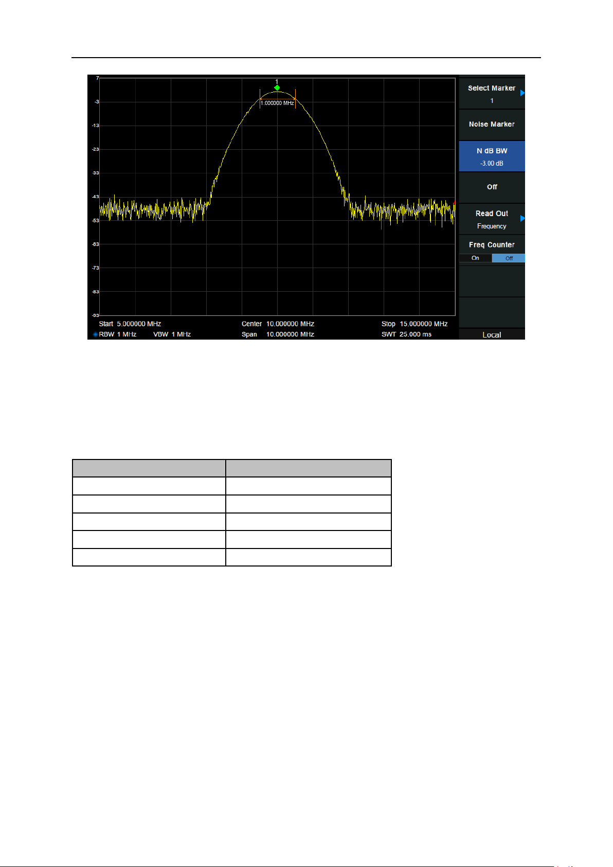
SIGLENT
Parameter
Explanation
Default
-3 dB
Range
-100 dB ~ 100 dB
Unit
dB
Knob Step
0.1 dB
Direction Key Step
1 dB
Figure 2-11 N dB BW
When the measurement starts, the analyzer will search for the two points which are located at both
sides of the current point with N dB fall or rise in amplitude and display the frequency difference
between the two points in the active function area. "----" would be displayed if the search fails.
Table 2-30 N dB Noise
2.3.3.4 Freq Counter
Turn on or off the frequency counter. The frequency readout is accuracy is up to 0.01 Hz.
The function is valid only when selecting marker 1.
If marker 1 is selected but not active, turning on the frequency counter will open marker 1 Normal
The frequency counter measures the frequency near the center frequency in Zero span.
2.3.3.5 Off
Turn off the noise marker, N dB BW measurement or Frequency Counter, but not the marker itself.
marker automatically.
SSA3000X Plus User Manual 49
Page 68

SIGLENT
2.3.3.6 Read Out
Select a desired readout type for the X-axis for the marker. Different markers can use different readout
types. This setting will change the readout type and affect the marker readings in the active function
area and at the upper right corner of the screen, but will not change the actual value.
1. Frequency
In this type, Normal marker shows the absolute frequency. Delta markers and Delta Pair markers show
the frequency difference between the delta marker and reference marker. The default readout mode in
non-zero span is “Frequency”.
Note: This type is invalid in Zero span.
2. Period
In this type, the Normal marker shows the reciprocal of frequency; while Delta marker and Delta Pair
marker show the reciprocal of frequency difference. When the frequency difference is zero, the
reciprocal is infinite and 100 Ts is displayed.
Note: This type is invalid in Zero span.
3. Δ Time
In this type, the Normal marker shows the time difference between the marker and the start of the
sweep; while Delta marker and Delta Pair marker show the sweep time difference between the delta
marker and reference marker.
The default readout mode in Zero span is Δ Time.
2.3.4 Peak
Open the peak search setting menu and execute peak search.
2.3.4.1 Peak -> CF
Execute peak search and set the center frequency of the analyzer to the frequency of the peak.
2.3.4.2 Next Peak
Search for and mark the peak whose amplitude is closest to that of the current peak and which meets
the peak search condition.
2.3.4.3 Next Left Peak
Search for and mark the nearest peak which is located at the left side of the current peak and meets the
peak search condition.
50 SSA3000X Plus User Manual
Page 69
SIGLENT
Parameter
Explanation
Default
-140 dBm
Range
-200 dBm ~ 200 dBm
Unit
dBm
Knob Step
1 dB
Direction Key Step
5 dB
2.3.4.4 Next Right Peak
Search for and mark the nearest peak which is located at the right side of the current peak and meets
the peak search condition.
2.3.4.5 Peak Peak
Execute peak search and minimum search at the same time and mark the results with delta pair
markers. Wherein, the result of peak search is marked with the delta marker and the result of minimum
search is marked with the reference marker.
2.3.4.6 Count Peak
Enable or disable continuous peak search. The default is Off. When enabled, the system will always
execute a peak search automatically after each sweep in order to track the signal under measurement.
2.3.4.7 Peak Table
Open the peak table (in the lower window) which lists the peaks (with frequency and amplitude) that
meet the peak search condition. Up to 16 peaks can be displayed in the table.
2.3.4.8 Search Config
Define the conditions of peak search for various peak searches. A real peak should meet the
requirements of both the “Peak Excursion” and “Peak Threshold”.
1. Peak Threshold
Assign a minimum for the peak amplitude. Peaks whose amplitudes are greater than the specified peak
threshold are treated as real peaks.
Table 2-31 Peak Threshold
2. Peak Excursion
Set the excursion between the peak and the minimum amplitude on both sides of it. Peaks whose
excursions are beyond the specified excursion are treated as real peaks.
SSA3000X Plus User Manual 51
Page 70
SIGLENT
Parameter
Explanation
Default
15 dB
Range
0 dB ~ 200 dB
Unit
dB
Knob Step
1 dB
Direction Key Step
5 dB
Table 2-32 Peak Excursion
3. Peak Type
Set the peak search condition. The available options are Maximum and Minimum.
52 SSA3000X Plus User Manual
Page 71

SIGLENT
2.4 Measurement
2.4.1 Meas
Provide optional measurement functions. When activated, the screen will be divided into two parts. The
above part is the measure screen which displays traces, and the other part is used to display
measurement results.
2.4.1.1 Channel Power
Measure the power and power density within the specified channel bandwidth. When this function is
enabled, the span and resolution bandwidth are automatically adjusted to smaller values. Select
Channel Power and press Meas Setup to set the corresponding parameters.
2.4.1.2 ACPR
Measure the power of the main channel and adjacent channels as well as the power difference
between the main channel and each of the adjacent channels. When this function is enabled, the span
and resolution bandwidth of the analyzer are adjusted to smaller values automatically.
Select ACPR and press Meas Setup to set the corresponding parameters.
2.4.1.3 Occupied BW
Integrates the power within the whole span and calculates the bandwidth occupied by this power
according to the specified power ratio. The OBW function also indicates the difference (namely
“Transmit Freq Error”) between the center frequency of the channel under measurement and the center
frequency of the analyzer. Select Occupied BW and press Meas Setup to set the corresponding
parameters.
2.4.1.4 T-Power
The system enters Zero span and calculates the power within the time domain. The types of powers
available include Peak, Average and RMS. Select T-Power and press Meas Setup to set the
corresponding parameters.
2.4.1.5 TOI
Automatic measurement of IP3 (Third order Intercept Point), including the power of fundamental wave
and the Third order in the power, and calculate the adjustable Intercept Point.
2.4.1.6 Spectrum Monitor
Display the power of the swept spectrum as an intensity color map commonly referred to as a waterfall
chart. Select Spectrum Monitor and press Meas Setup to set the corresponding parameters.
SSA3000X Plus User Manual 53
Page 72
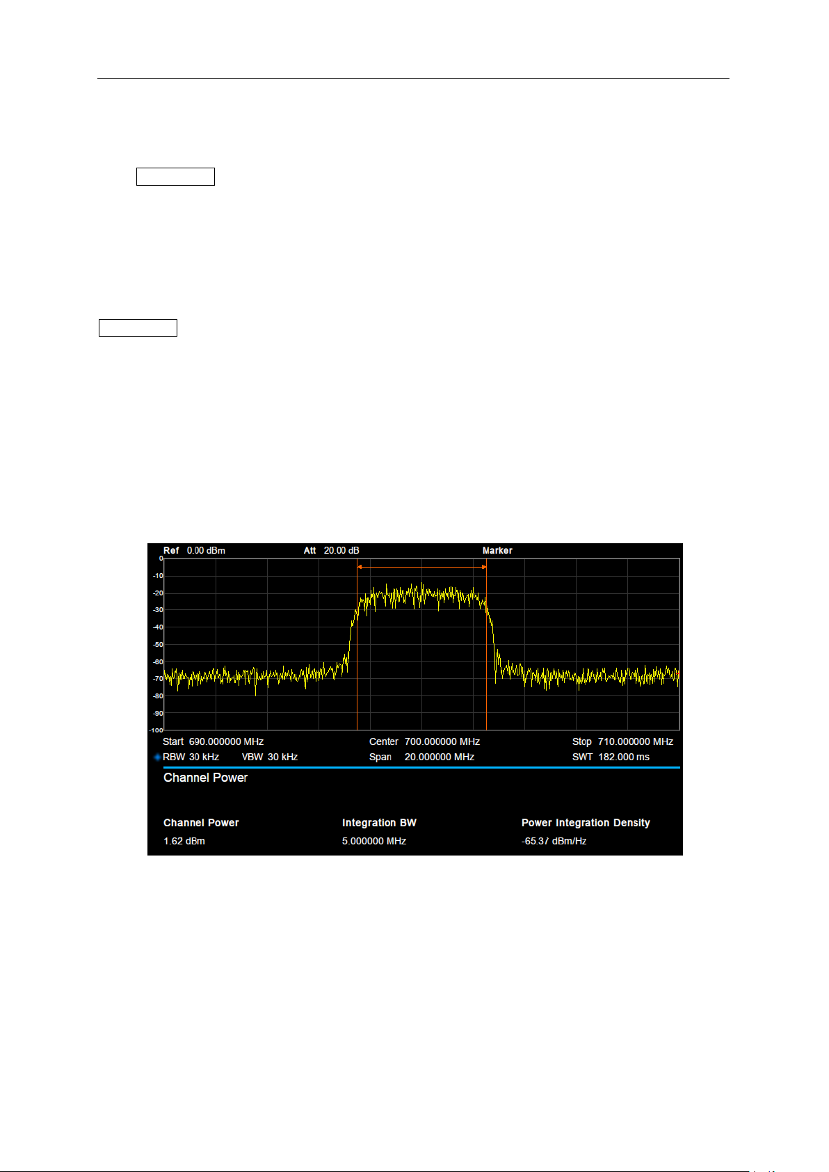
SIGLENT
2.4.1.7 CNR
Measure the power of the carrier and noise of the specified bandwidth and their ratio. Select CNR and
press Meas Setup to set the corresponding parameters.
2.4.1.8 Harmonics
The harmonic power and total harmonic distortion of carrier signal are measured. The maximum
measurable harmonic is 10th harmonic. The fundamental wave amplitude of carrier signal must be
greater than - 50 dBm, otherwise the measurement result is invalid. Select Harmonics and press
Meas Setup to set the corresponding parameters.
2.4.1.9 Meas Off
Turn off all the Meas functions.
2.4.2 Meas setup
2.4.2.1 Channel Power
Figure 2-12 Channel Power
Measurement Results: Channel power and power spectral density.
Channel Power: Power within the integration bandwidth.
Power Spectral Density: Power (in dBm/Hz) normalized to 1Hz within the integration bandwidth.
Measurement Parameters: Center Freq, Integration BW, Span, Span power.
1. Center Freq
54 SSA3000X Plus User Manual
Page 73
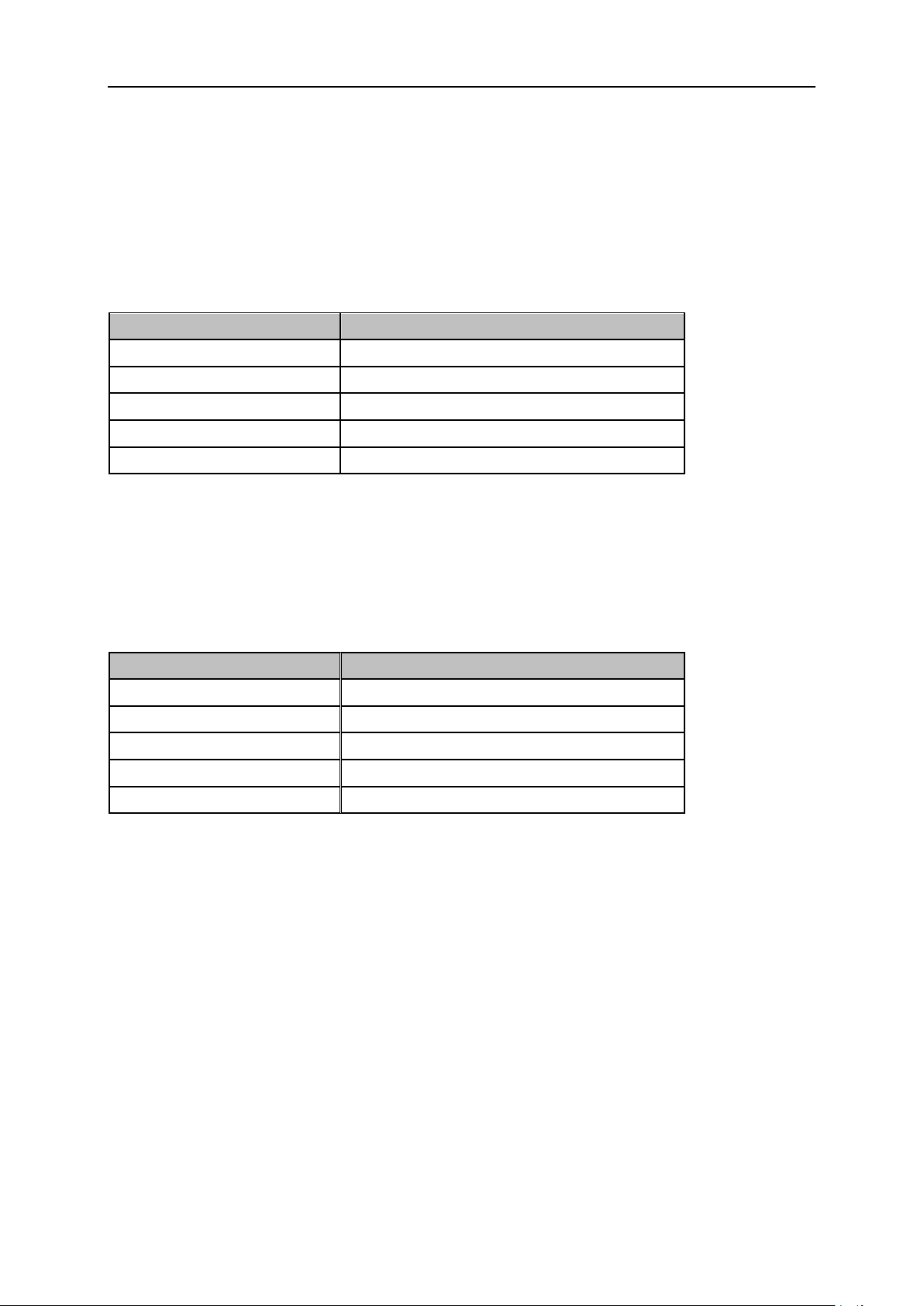
SIGLENT
Parameter
Explanation
Default
2 MHz
Range
100 Hz ~ Span
Unit
GHz, MHz, kHz, Hz
Knob Step
Integration BW/100, the minimum is 1 Hz
Direction Key Step
In 1-1.5-2-3-5-7.5 sequence
Parameter
Explanation
Default
current span
Range
100 Hz ~ Span
Unit
GHz, MHz, kHz, Hz
Knob Step
Channel Power Span/100, the minimum is 1Hz
Direction Key Step
In 1-1.5-2-3-5-7.5 sequence
Set the center frequency, this center frequency which is the same with the center frequency of the
analyzer. Modifying this parameter will change the center frequency of the analyzer.
2. Integration BW
Set the frequency width of the channel to be tested and the power of the channel is the power integral
within this bandwidth. You can use the numeric keys, knob or direction keys to modify this parameter.
Table 2-33 Integration BW
3. Span
Set the frequency range of the channel. This span which is the same with the span of the analyzer is
the frequency range of the sweep. Modifying this parameter will change the span of the analyzer.
The channel power span is related to the integration bandwidth.
Table 2-34 Channel Power Span for Chan Power Measurement
4. Span Power
Set the integrated bandwidth to the sweep span of display. The channel power and power spectral
density display on the screen simultaneously.
SSA3000X Plus User Manual 55
Page 74
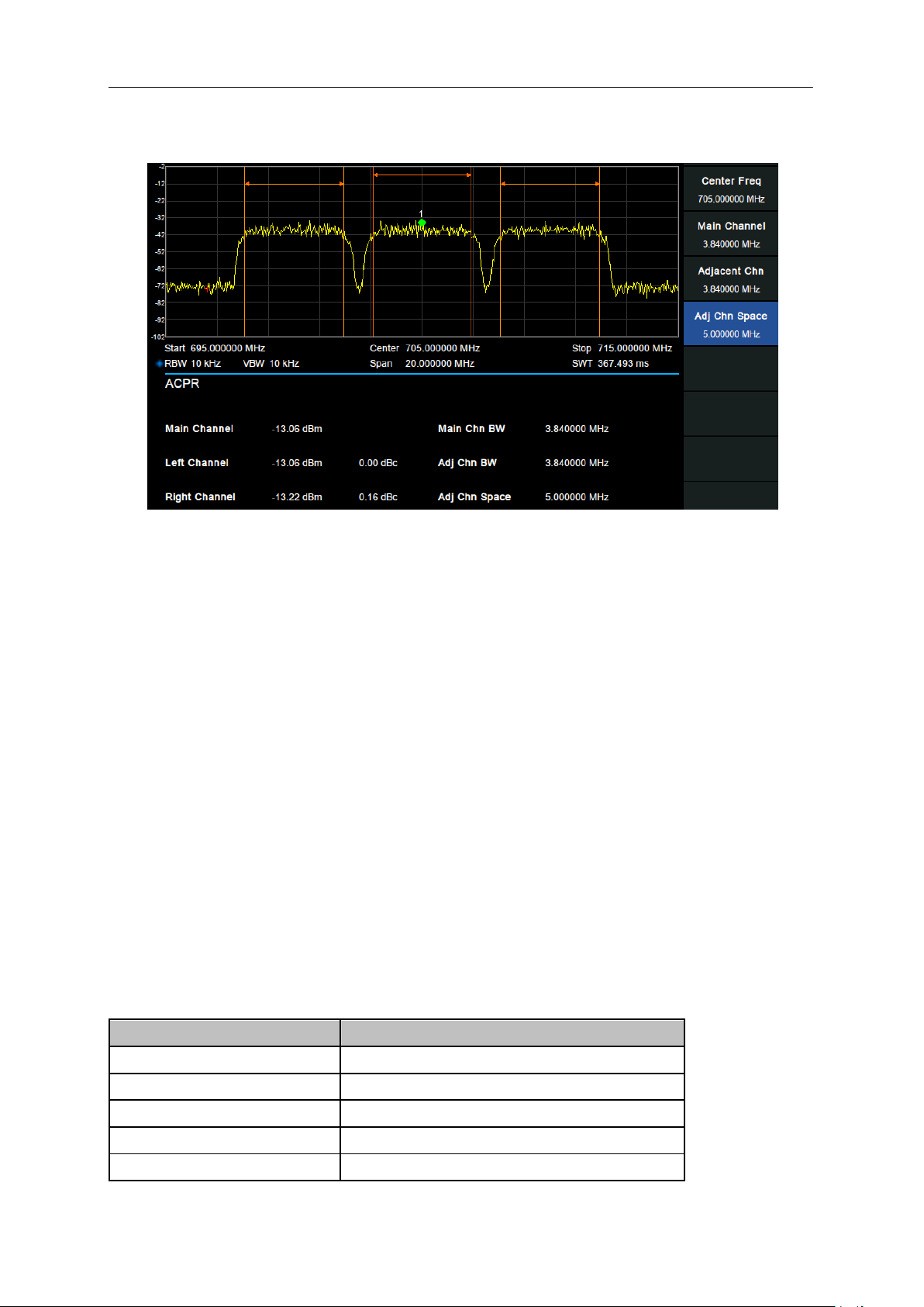
SIGLENT
Parameter
Explanation
Default
1 MHz
Range
100 Hz ~ full span
Unit
GHz, MHz, kHz, Hz
Knob Step
Main Channel /10, the minimum is 1 Hz
Direction Key Step
In 1-1.5-2-3-5-7.5 Sequence
2.4.2.2 ACPR
Figure 2-13 ACPR
Measurement Results: Main CH Power, Left channel power and Right channel power.
Main CH Power: Displays the power within the bandwidth of the main power
Left channel power : Displays the power of left channel and the power difference between the left
channel and the main channel (in dBc)
Right channel power: Display the power of the right channel and the power difference between the
right channel and the main channel(in dBc)
Measurement parameter: Center frequency, main channel bandwidth, adjacent channel bandwidth
and channel spacing
1. Center Freq
Set the center frequency. The center frequency is the same with the center frequency of the analyzer
display. Modifying this parameter will change the center frequency of the analyzer.
2. Main Channel
Set the bandwidth of the main channel and the power of the main channel is the power integral within
this bandwidth.
Table 2-35 Main Channel
56 SSA3000X Plus User Manual
Page 75
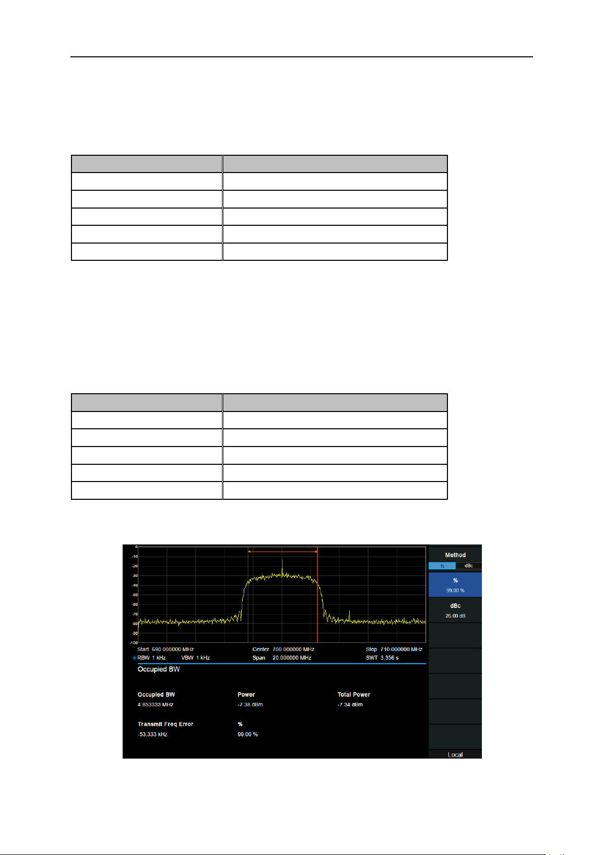
SIGLENT
Parameter
Explanation
Default
1 MHz
Range
100 Hz ~ (full span - 2*100 Hz)
Unit
GHz, MHz, kHz, Hz
Knob Step
Adjacent Chn/10, the minimum is 1 Hz
Direction Key Step
In 1-1.5-2-3-5-7.5 Sequence
Parameter
Explanation
Default
3 MHz
Range
100 Hz ~ (full span – 100 Hz) /2
Unit
GHz, MHz, kHz, Hz
Knob Step
Adj Chn space /10, the minimum is 1 Hz
Direction Key Step
In 1-1.5-2-3-5-7.5 Sequence
3. Adjacent Chn
Set the frequency width of the adjacent channels.
The adjacent channel bandwidth is related to the main channel bandwidth.
Table 2-36 Adjacent channel bandwidth
4. Adj Chn space
Set the difference between the center frequency of the main channel and the center frequency of the
adjacent channels.
Adjusting this parameter will also adjust the distance between the upper/lower channel and the main
channel.
Table 2-37 adjacent channel space
2.4.2.3 OBW
Figure 2-14 OBW
SSA3000X Plus User Manual 57
Page 76
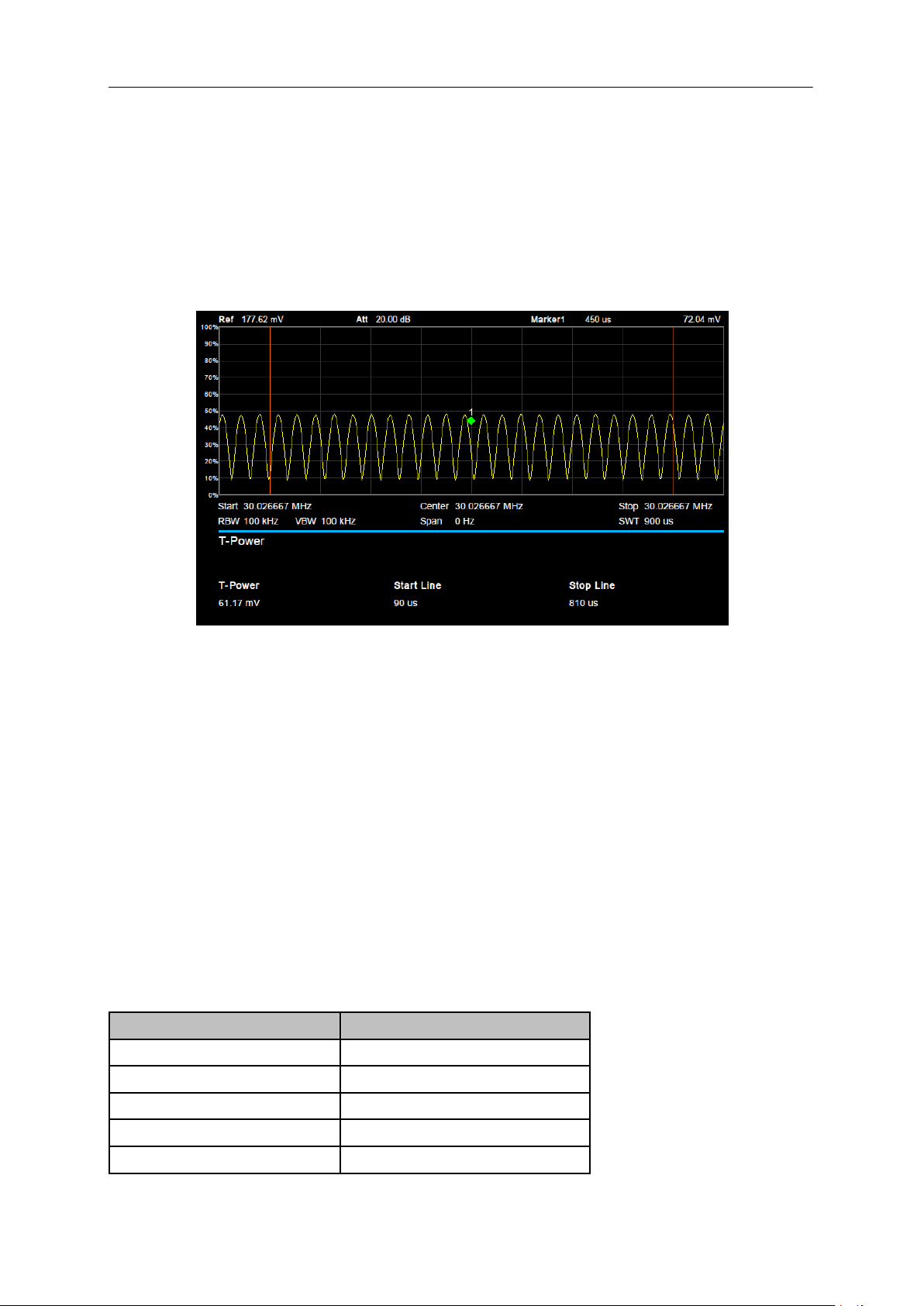
SIGLENT
Parameter
Explanation
Default
0 s
Range
0 s ~ stop line
Unit
ks, s, ms, us, ns
Knob Step
Sweep time/751
Direction Key Step
In 1-1.5-2-3-5-7.5 Sequence
Measurement Results: occupied bandwidth and transmit frequency error.
Occupied Bandwidth: Integrates the power within the whole span and then calculates the
bandwidth occupied by the power according to the specified power ratio.
Transmit Frequency Error: The difference between the center frequency of the channel and the
center frequency of the analyzer.
2.4.2.4 T-Power
Figure 2-15 T-Power
Measurement Results: T-Power
T-Power: The power of the signal from the start line to the stop line.
Measurement Parameter: Center frequency, start line, stop line.
1. Center Frequency
Set the center frequency, this center frequency which is the same with the center frequency of the
analyzer. Modifying this parameter will change the center frequency of the analyzer.
2. Start line
Set the left margin (in time unit) of T-Power measurement. The data calculated under this measurement
is between the start line and stop line.
Table 2-38 start line
58 SSA3000X Plus User Manual
Page 77
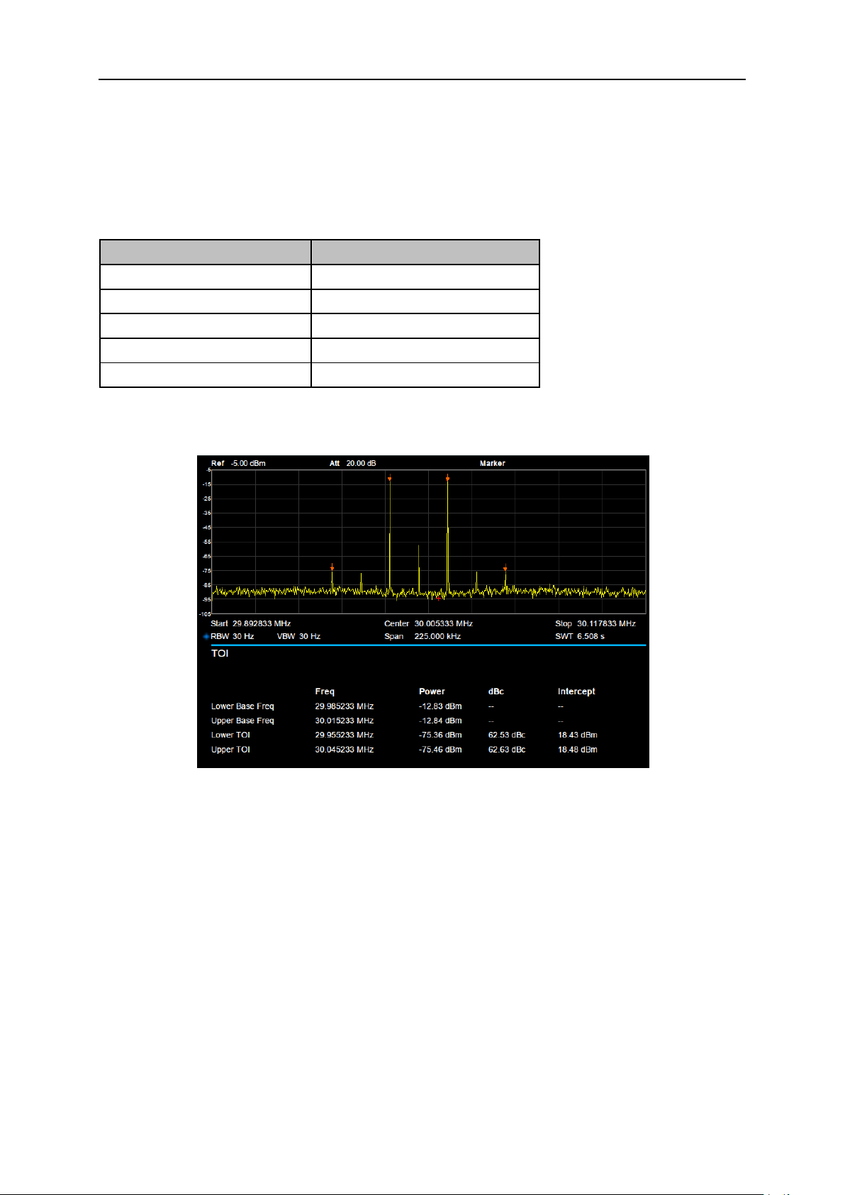
SIGLENT
Parameter
Explanation
Default
900 us
Range
Start line ~ sweep time
Unit
ks, s, ms, us, ns
Knob Step
Sweep time /751
Direction Key Step
In 1-1.5-2-3-5-7.5 Sequence
3. Stop line
Set the right margin (in time unit) of T-Power measurement. The data calculated under this
measurement is between the start line and stop line.
Table 2-39 stop line
2.4.2.5 TOI
Figure 2-16 TOI
TOI is an automatic measurement. There are no user controlled parameters.
SSA3000X Plus User Manual 59
Page 78
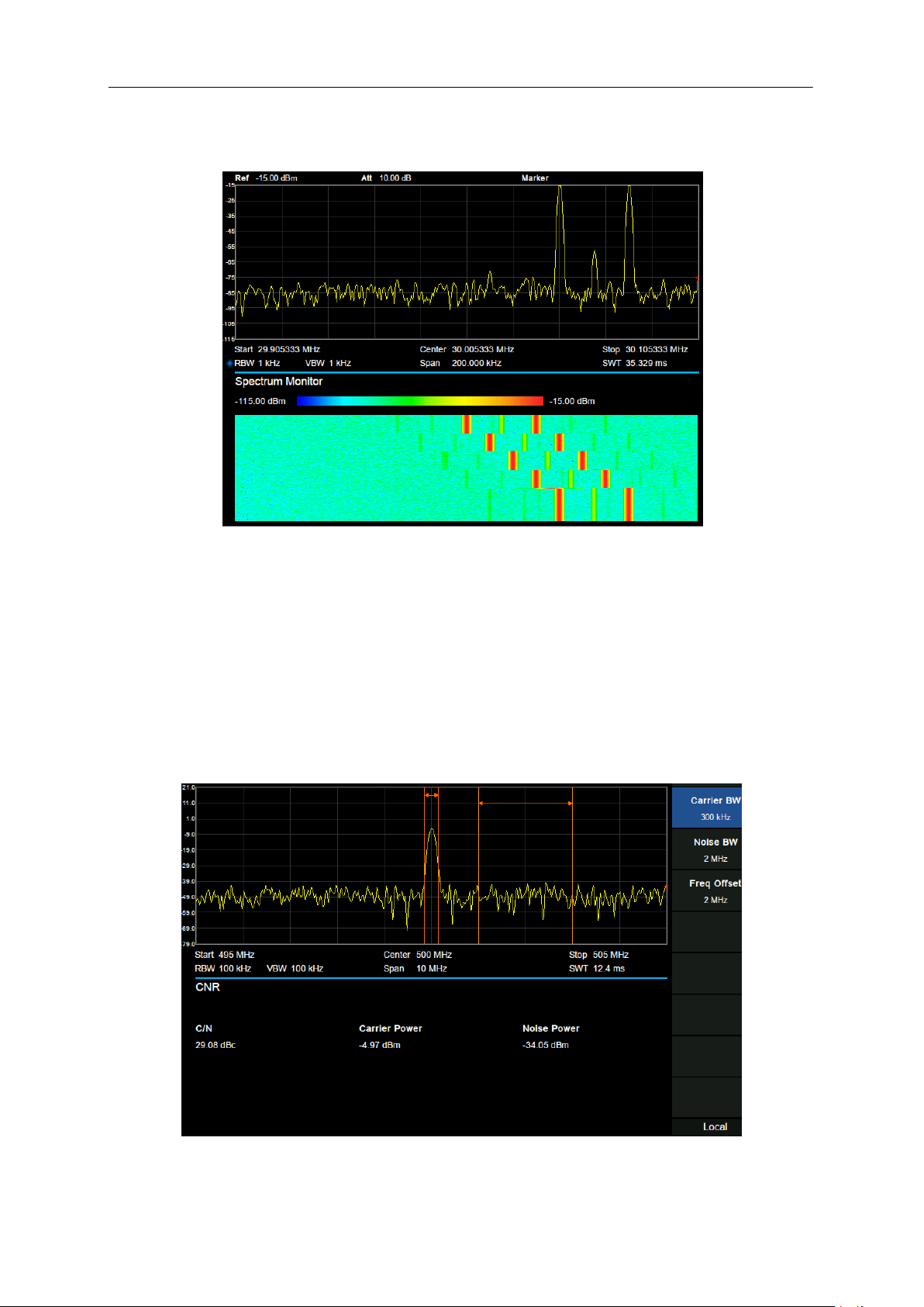
SIGLENT
2.4.2.6 Spectrum Monitor
Figure 2-17 Spectrum Monitor
Display the power of spectrum of successive scans as a color map. Also call a waterfall chart.
Measurement Parameter: Spectrogram, Restart.
1. Spectrogram: Sets the meas state of spectrum monitor.
2. Restart: clear the measurement and then restart it.
2.4.2.7 CNR
60 SSA3000X Plus User Manual
Figure 2-18 CNR
Page 79
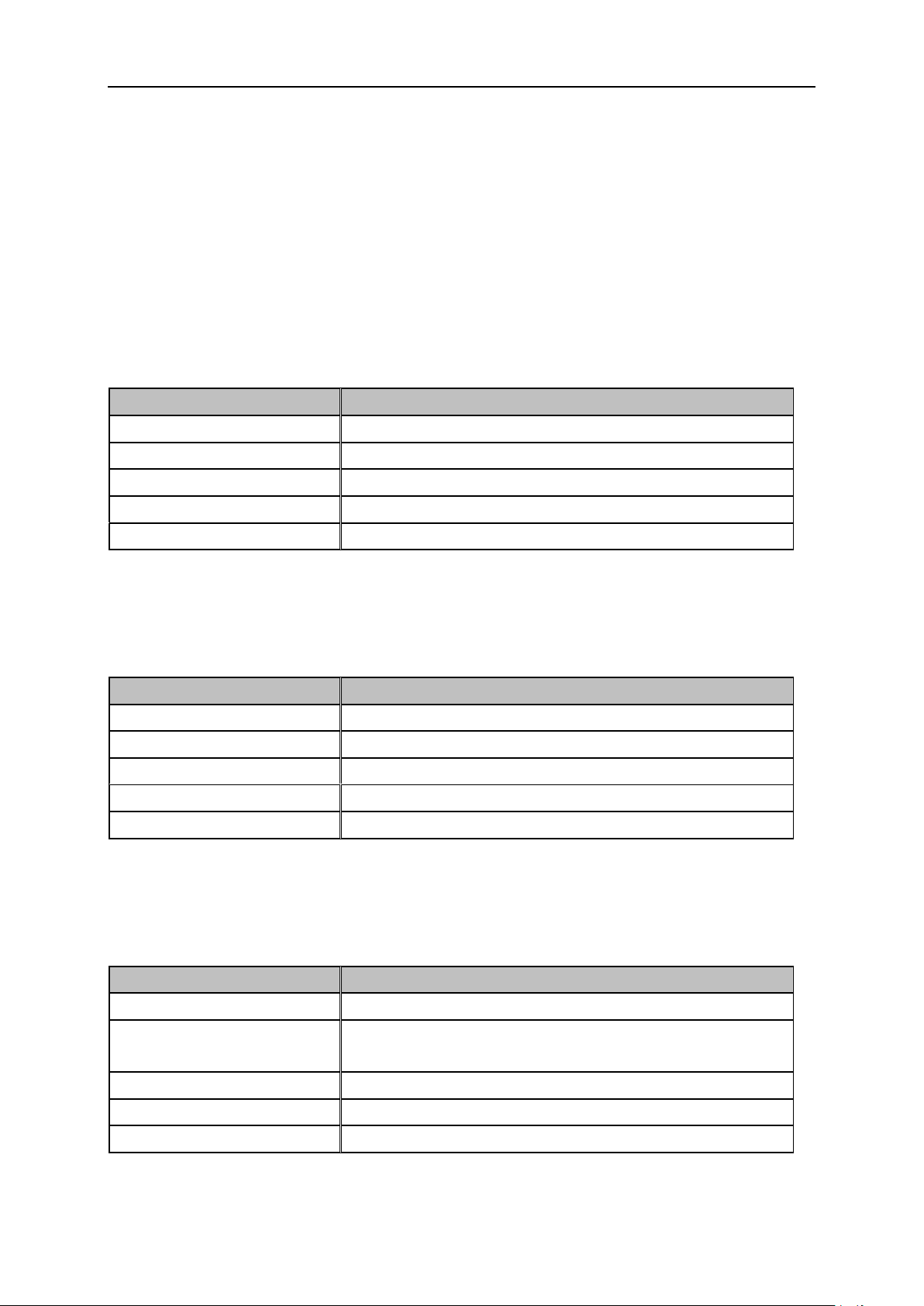
Measurement Results: C/N, Carrier Power, Noise Power.
Parameter
Explanation
Default
3 MHz
Range
100 Hz ~ (2*span - 2*|Freq Offset| - Noise BW)
Unit
GHz, MHz, kHz, Hz
Knob Step
Carrier BW /10, the minimum is 1 Hz
Direction Key Step
In 1-1.5-2-3-5-7.5 Sequence
Parameter
Explanation
Default
3 MHz
Range
100 Hz ~ (2*span - 2*|Freq Offset| - Carrier BW)
Unit
GHz, MHz, kHz, Hz
Knob Step
Noise BW /10, the minimum is 1 Hz
Direction Key Step
In 1-1.5-2-3-5-7.5 Sequence
Parameter
Explanation
Default
3 MHz
Range
-(span - (Carrier BW + Noise BW) /2) ~
(span - (Carrier BW + Noise BW) /2)
Unit
GHz, MHz, kHz, Hz
Knob Step
Freq Offset /10, the minimum is 1 Hz
Direction Key Step
In 1-1.5-2-3-5-7.5 Sequence
C/N: the ratio of Carrier Power to Noise Power.
Carrier Power: the total power of the carrier bandwidth.
Noise Power: the total power of the selected noise bandwidth.
Measurement Parameter: Carrier BW, Noise BW, Freq Offset.
1. Carrier BW
Set the bandwidth of the carrier to be measured.
Table 2-40 Carrier BW
SIGLENT
2. Noise BW
Set the bandwidth of the noise to be measured.
Table 2-41 Noise BW
3. Freq Offset
Set the difference between carrier center frequency and noise center frequency.
Table 2-42 Freq Offset
SSA3000X Plus User Manual 61
Page 80
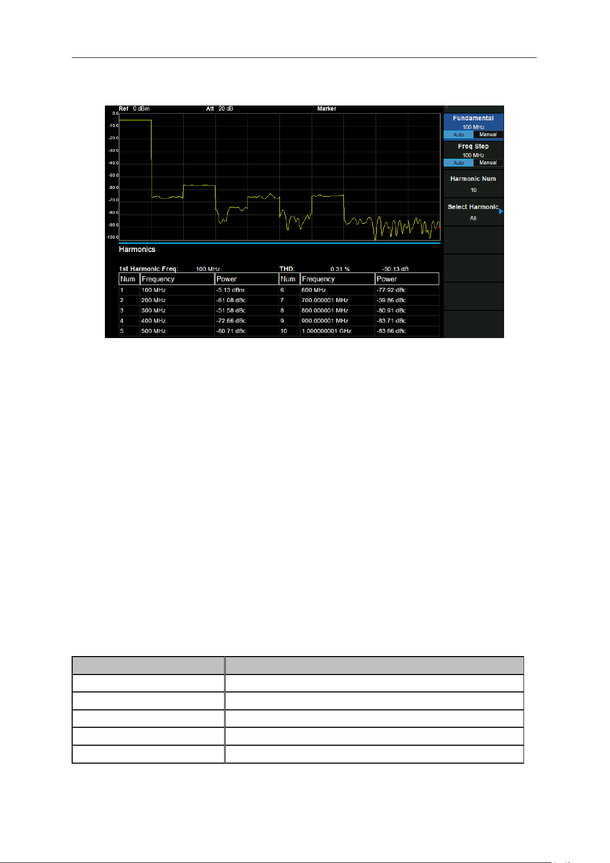
SIGLENT
Parameter
Explanation
Default
10
Range
2 ~ 10
Unit
None
Knob Step
1
Direction Key Step
1
2.4.2.8 Harmonics
Figure 2-19 Harmonics
Measurement Results: each harmonic amplitude and total harmonic distortion of carrier signal. It can
measure up to 10th harmonic.
Measurement Parameter:
1. Fundamental
Set the frequency of the fundamental wave.
If the automatic mode is turned on, the fundamental wave will be automatically found from the first scan.
If the automatic mode is turned off, the user can input the fundamental frequency manually.
2. Freq Step
Set the harmonic step. In auto mode, the frequency of a harmonic is a multiple of the fundamental
frequency.
3. Harmonic Num
Set the total number of the harmonics to be measured.
Table 2-43 Harmonic Num
62 SSA3000X Plus User Manual
Page 81

SIGLENT
4. Select Harmonic
When "All" is selected, the trace shows the fundamental wave and all harmonics in the sweep
bandwidth.
When 1-10 is selected, the trace shows a zero span trace corresponding to the fundamental wave or
the measured harmonic.
SSA3000X Plus User Manual 63
Page 82

SIGLENT
Chapter 3 Modulation Analyzer
This chapter introduces in detail the function keys and menu functions of the front panel under the
Modulation Analyzer Mode.
This mode enables modulation analysis of incoming signals. Modulation types are as follows:
AM analog modulation
FM analog modulation
ASK digital modulation
FSK digital modulation
2FSK, 4FSK, 8FSK, 16FSK
MSK digital modulation
PSK digital modulation
BPSK, QPSK, 8PSK, DBPSK, DQPSK, D8PSK, Pi/4 DQPSK, Pi/8 D8PSK, OQPSK
QAM digital modulation
16QAM, 32QAM, 64QAM, 128QAM, 256QAM
Meas menu may be different in different modulation types.
The modulation type can be re-selected by pressing the Meas key.
Subjects in this chapter:
Basic Settings
Measurement
Sweep and Functions
64 SSA3000X Plus User Manual
Page 83
SIGLENT
Parameter
Explanation
Default
100 MHz
Range
Full Span
Unit
GHz, MHz, kHz, Hz
Knob Step
Freq Step/10
Direction Key Step
Freq Step
Parameter
Explanation
Default
10 kHz
Range
1 Hz ~ 100 MHz
Unit
GHz, MHz, kHz, Hz
Knob Step
Freq Step/10, min 1 Hz
Direction Key Step
In 1-2-5 sequence
3.1 Basic Settings
3.1.1 Frequency
Switch to the Frequency Settings menu by pressing Frequency on the front panel. When entering the
frequency menu, the “Center Freq” is selected by default.
3.1.1.1 Center Freq
Set the modulated carrier frequency.
Table 3-1 Center Freq
3.1.1.2 Freq Step
Setting the value of Freq Step will change the direction key step and knob step of the center frequency.
Table 3-2 Freq Step
3.2 Measurement
3.2.1 Digital Modulation Analysis
When ASK, FSK, MSK, PSK or QAM modulation type is selected, digital modulation analysis is carried
out.
3.2.1.1 Format
Select the modulation format.
SSA3000X Plus User Manual 65
Page 84
SIGLENT
Parameter
Explanation
Default
10 ksps
Range
1 ksps ~ 2.5 Msps
Unit
Msps, ksps, sps
Knob Step
Symbol Rate/10
Direction Key Step
In 1-2-5 sequence
Parameter
Explanation
Default
128
Range
16 ~ 4096
Unit
1
Knob Step
1
Direction Key Step
Current value of Meas Length
3.2.1.2 Symbol Rate
Set the symbol rate of the signal to be analyzed. Press Meas Setup, then select "Symbol Rate", you
can input the symbol rate and change the symbol rate by the knob.
Table 3-3 Symbol Rate
3.2.1.3 Points/Symbol
Set the points/symbol of the modulated signal.
3.2.1.4 Meas Length
Set the number of symbols which will be used in calculating the measurement. As the length is longer,
the range for statistics is bigger, and the measure time is longer.
Table 3-4 Meas Length
3.2.1.5 Filter Setup
After entering into the "Filter Setup" sub-menu, you can choose the relative parameters of filters.
1. Measure Filter
Sqrt Nyquist
Nyquist
Gauss
Half Sine
Off
2. Reference Filter
Sqrt Nyquist
Nyquist
66 SSA3000X Plus User Manual
Page 85
SIGLENT
Transmitter Filter
Measure Filter
Reference Filter
Sqrt Nyquist
Sqrt Nyquist
Nyquist
Nyquist
Off
Nyquist
Gauss
Off
Gauss
Half Sine
Off
Half Sine
Parameter
Explanation
Default
0.35
Range
0 ~ 1
Unit
1
Knob Step
0.01
Direction Key Step
0.1
Parameter
Explanation
Default
64
Range
2 ~ 128
Unit
1
Knob Step
1
Direction Key Step
5
Gauss
Half Sine
Off
Note: The rule of common filter type selected
3. Filter Alpha/BT
For Sqrt Nyquist and Nyquist filter settings, you can set the alpha parameter. It can be set the
same as the transmitter.
For a Gauss filter, use the BT parameter. It can be set the same as the transmitter.
Table 3-5 Filter Parameter
4. Filter Length
Set the symbols number of the filter selected. It can be set the same as the transmitter.
Table 3-6 Filter Length
3.2.1.6 Statistic
1. Statistic
Turn on the statistical function, the measurement result will show the maximum and minimum of
statistics. Turn off the statistical function, the measurement result will only show the real-time
measurement value. Statistical function is turned off by default.
SSA3000X Plus User Manual 67
Page 86
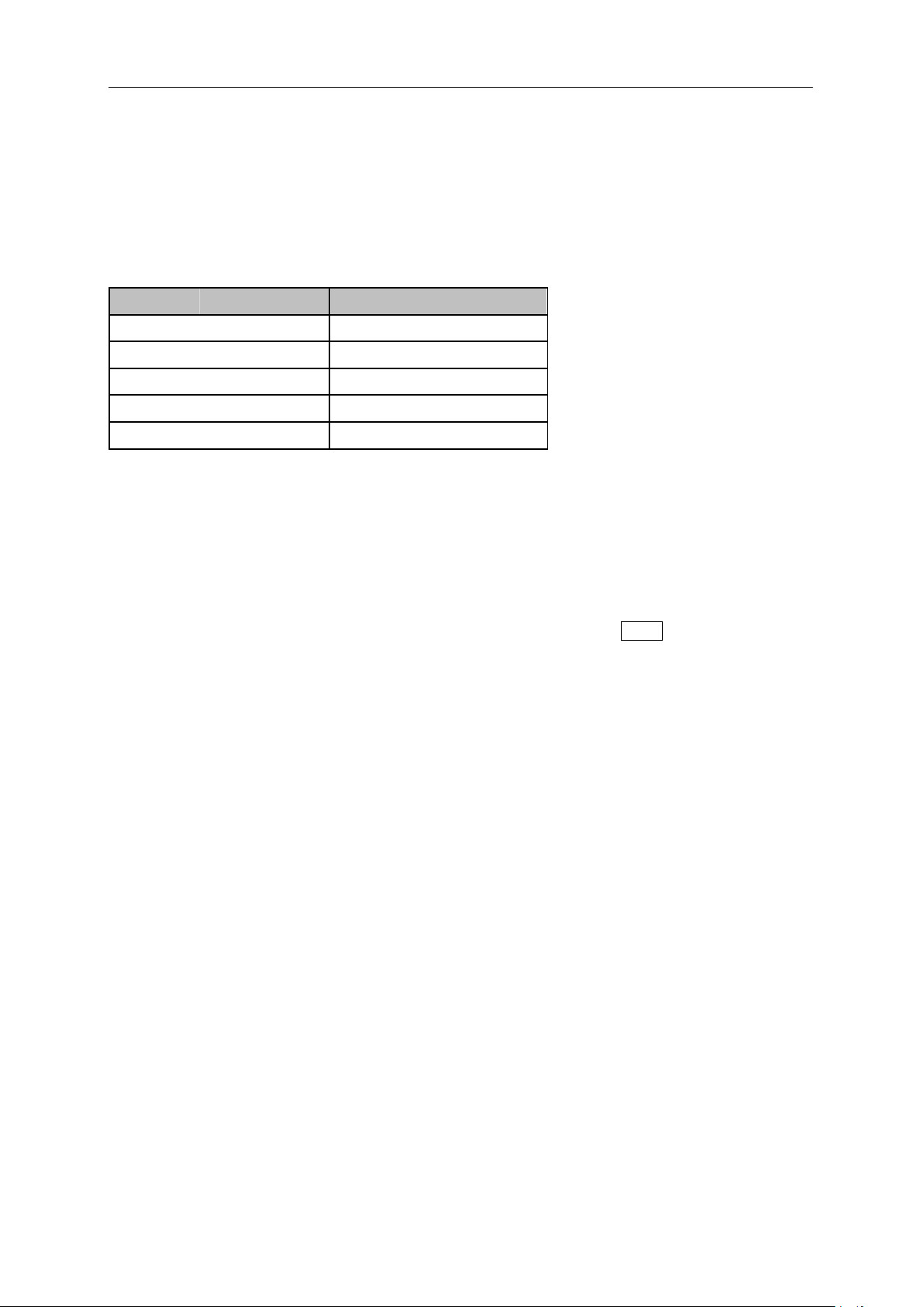
SIGLENT
Parameter
Explanation
Default
10
Range
1 ~ 1000
Unit
1
Knob Step
1
Direction Key Step
10
2. Avg
Open and close the average option for the measurement result. It can set the average number. When
the Avg Number is set to off, the column title "Average" in numerical results view will be changed to
"Current". The "Average" measurement result will be stable if the average number is set to larger
values.
Table 3-7 Avg Number
3. Restart Meas
After this function is performed, the statistics will be cleared and restarted. If the average function is
turned on, the average calculation of measurement results will be cleared and restarted as well.
3.2.1.7 Trace
The displayed data and format in the measurement windows can be set in Trace menu.
1. Select Trace
Select the trace in order to set the corresponding trace parameters. You can also select the trace by
clicking on the trace mark displayed in the left status bar of the screen.
2. Num of Traces
Set the upper limit of displayed trace numbers. Up to four traces can be displayed simultaneously in the
screen window.
3. Layout
Select the layout of the screen windows. The layout types are as follows:
Single
Stacked 2
Grid 1,2
Grid 2x2
4. Data
Select the displayed data of the trace.
5. Format
Select the displayed format of the trace.
68 SSA3000X Plus User Manual
Page 87
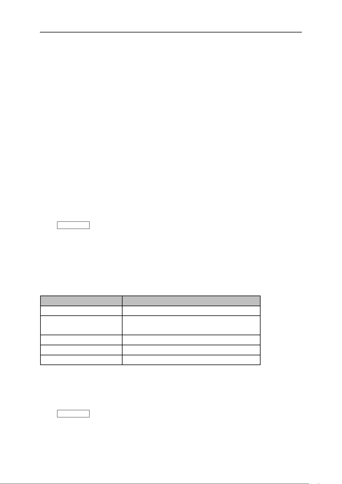
6. Copt to
Parameter
Explanation
Default
1.2 MHz
Range
1.2 MHz, 960 kHz, 600 kHz, 480 kHz, 300 kHz,
240 kHz, 120 kHz, 96 kHz, 60 kHz
Unit
MHz, kHz
Knob Step
Change to the next enumeration value
Direction Key Step
Change to the next enumeration value
Copy the currently selected trace to another trace.
7. Properties
Eye Length
Set the length of the Eye diagram.
Symbol Table
Display the demodulation digital symbols (binary or hex).
3.2.2 Analog Modulation Analysis
When AM or FM modulation type is selected, analog modulation analysis is carried out.
3.2.2.1 IFBW
SIGLENT
After entering into the mode AM or FM modulation analysis, set the intermediate frequency bandwidth
(IFBW).
Press Meas Setup, you can set the "IFBW" again.
It specifies the IFBW of the signal to be analyzed. The measurement accuracy will be impacted if this
value isn't set precisely. The IFBW should be as narrow as possible to improve the S/N ratio.
For AM modulation analysis, the IFBW should be larger than twice the modulation frequency. For FM
modulation analysis, the IFBW should be larger than twice the sum of the deviation frequency and the
modulation frequency.
Table 3-8 IFBW
3.2.2.2 EqLPF
After entering into the mode AM modulation analysis or FM modulation analysis, set the equivalent low
pass filter (EqLFP).
Press Meas Setup, you can set the "EqLFP" again.
It specifies the EqLPF bandwidth of the signal to be analyzed. The measurement accuracy will be
impacted if this value isn't set precisely. The EqLPF is an additional low pass filter. It can conveniently
SSA3000X Plus User Manual 69
Page 88
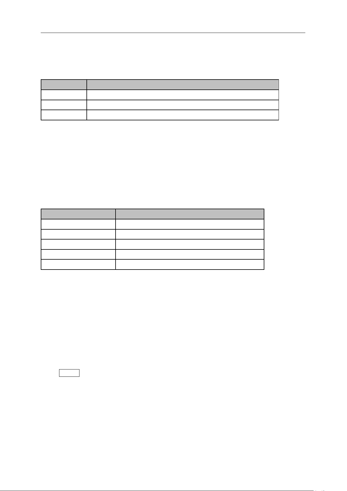
SIGLENT
Parameter
Explanation
Default
IFBW/6
Range
Off, IFBW/6, IFBW/20, IFBW/60, IFBW/200, IFBW/600, IFBW/2000
Unit
kHz、Hz
Parameter
Parameter
Default
10
Range
1 ~ 1000
Unit
1
Knob Step
1
Direction Key Step
10
measure the lower modulation frequency signal. The EqLPF bandwidth should be as narrow as
possible to improve the S/N ratio, but also need to be larger than the modulation frequency.
Table 3-9 EqLPF
3.2.2.3 Average
Open and close the average option for the measurement result. It can set the average number. When
the Avg Number is set to off, the column title "Average" in numerical results view will be changed to
"Current". The "Average" measurement result will be stable if the average number is set to larger
values.
Table 3-10 Avg Number
3.2.2.4 Restart Meas
After this function is performed, the statistics will be cleared and restarted. If the average function is
turned on, the average calculation of measurement results will be cleared and restarted as well.
3.3 Sweep and Functions
3.3.1 Trigger
Press Trigger to open the menu. The analyzer will begin a sweep only with the selected trigger
conditions are met. A trigger event is defined as the point at which your trigger source signal meets the
specified trigger level.
Free Run: New sweep starts as soon as possible after the current sweep ends.
RF Trigger: Activates the trigger condition that starts the next sweep if the detected RF envelops
voltage rises to a level set by the RF trigger level.
External: The trigger even is the rising or falling edge of the external trigger signal.
70 SSA3000X Plus User Manual
Page 89

SIGLENT
3.3.2 Sweep
Select "single" or "continue" type for sweep. Press Sweep into the menu. When "single" sweep type is
selected, it will start a new sweep if meets the trigger even, after press the menu button "single".
Single Sweep
Continue Sweep
SSA3000X Plus User Manual 71
Page 90

SIGLENT
Chapter 4 System Settings
4.1 System
4.1.1 Language
The analyzer supports a multi-language menu, Chinese and English built-in help and popup messages.
Press this key to select the desired display language.
4.1.2 Power On/Preset
4.1.2.1 Power On
Set the power on setting to Default, Last or User.
Def: Load the default settings, for more details please refer to Table 4-3.
Last: When Last is selected, instrument settings before the last power-off are recalled
automatically at power on.
User: If power on is set to user, the device will recall the specified configuration after power on.
4.1.2.2 Preset
Set the preset type to Default, Last or User.
Def: When press Preset, load the default settings, for more details please refer to Table 4-3.
Last: When press Preset, load the last power-off settings.
User: When press Preset, load the specified configuration type.
4.1.2.3 User Config
Save the current instrument settings as user-defined setting into the internal non-volatile memory.
4.1.2.4 Factory Reset
When Factory Reset is selected, the device will recall the initial config.
4.1.2.5 Reset & Clear
When Reset & Clear is selected, the device will recall the initial config and all user data and settings
will be erased.
4.1.2.6 Power on Line
Set whether the instrument will start automatically after power-on. Default does not automatically start.
72 SSA3000X Plus User Manual
Page 91
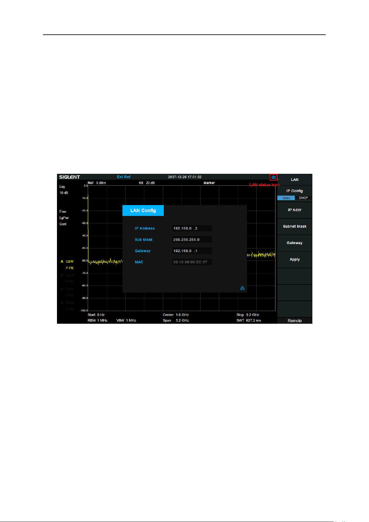
SIGLENT
4.1.3 Interface
The analyzer supports communications through LAN, USB and the SIGLENT USB-GPIB adapter as
standard remote computer control interfaces.
4.1.3.1 LAN
Configure the related parameters of the LAN connection by “Static” or “DHCP” method. As a default,
the IP config is DHCP.
Statically setting LAN parameters requires pressing the "Apply" button to make LAN parameters
effective.
When “DHCP” is pressed, the LAN parameters are dynamically allocated.
The LAN status icon will be displayed in the upper right corner of the screen if the cable is connected.
Figure 4-1 LAN Config
4.1.3.2 GPIB
Configure GPIB port number. The analyzer provides a digital interface for use with an optional
SIGLENT USB-GPIB module through the front USB port.
4.1.3.3 Web Server
Set web page parameters to use VNC.
1. Port
The port number can be set to 5900~5999. When the port number is set beyond the range, a prompt
pops up at the bottom of the screen, and the port number is automatically set to the maximum or
minimum value.
After modifying the port number, VNC needs to be reopened.
SSA3000X Plus User Manual 73
Page 92
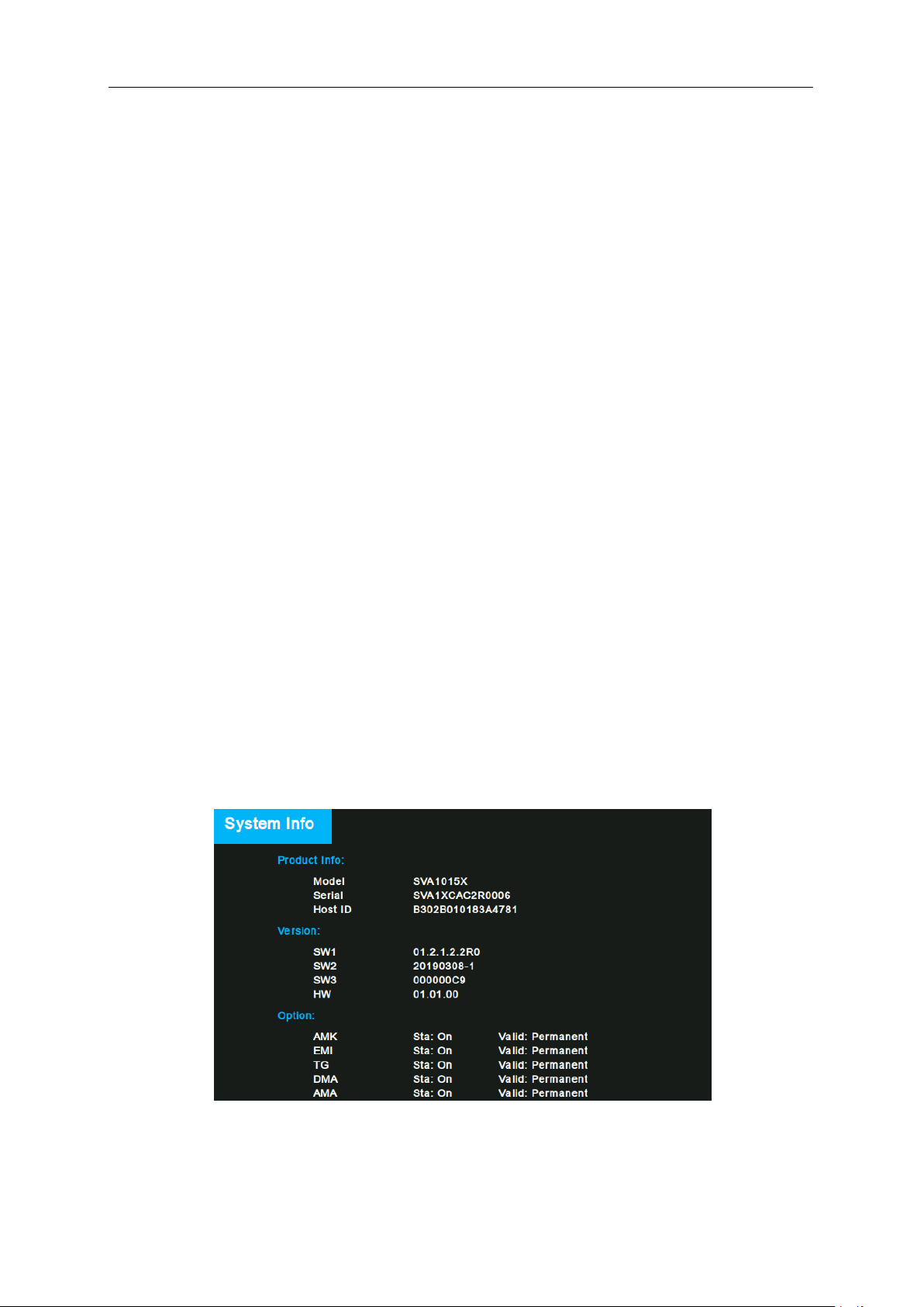
SIGLENT
2. Password
Set the password for login VNC.
3. View Only
Set whether the analyzer is in view-only mode on VNC.
When the view-only mode is turned on, the analyzer can only be viewed and cannot be operated on
VNC. When the view-only mode is turned off, the analyzer can be viewed and operated simultaneously
on VNC.
After modifying the view-only mode, VNC needs to be reopened.
4.1.4 Calibration
4.1.4.1 Auto Cal
Set whether to turn on the auto calibration or not and turn off by default. When Auto Cal is turned on,
the analyzer will process self-calibration according to the temperature difference. Half an hour after
startup, the device will query temperature itself every minute. If the temperature difference is greater
than 2°, the device will be self-calibrated.
4.1.5 System Info
4.1.5.1 System Info
Product Model, Serial and HOST ID
Software Version and Hardware Version
Option Information
74 SSA3000X Plus User Manual
Figure 4-2 System Info
Page 93
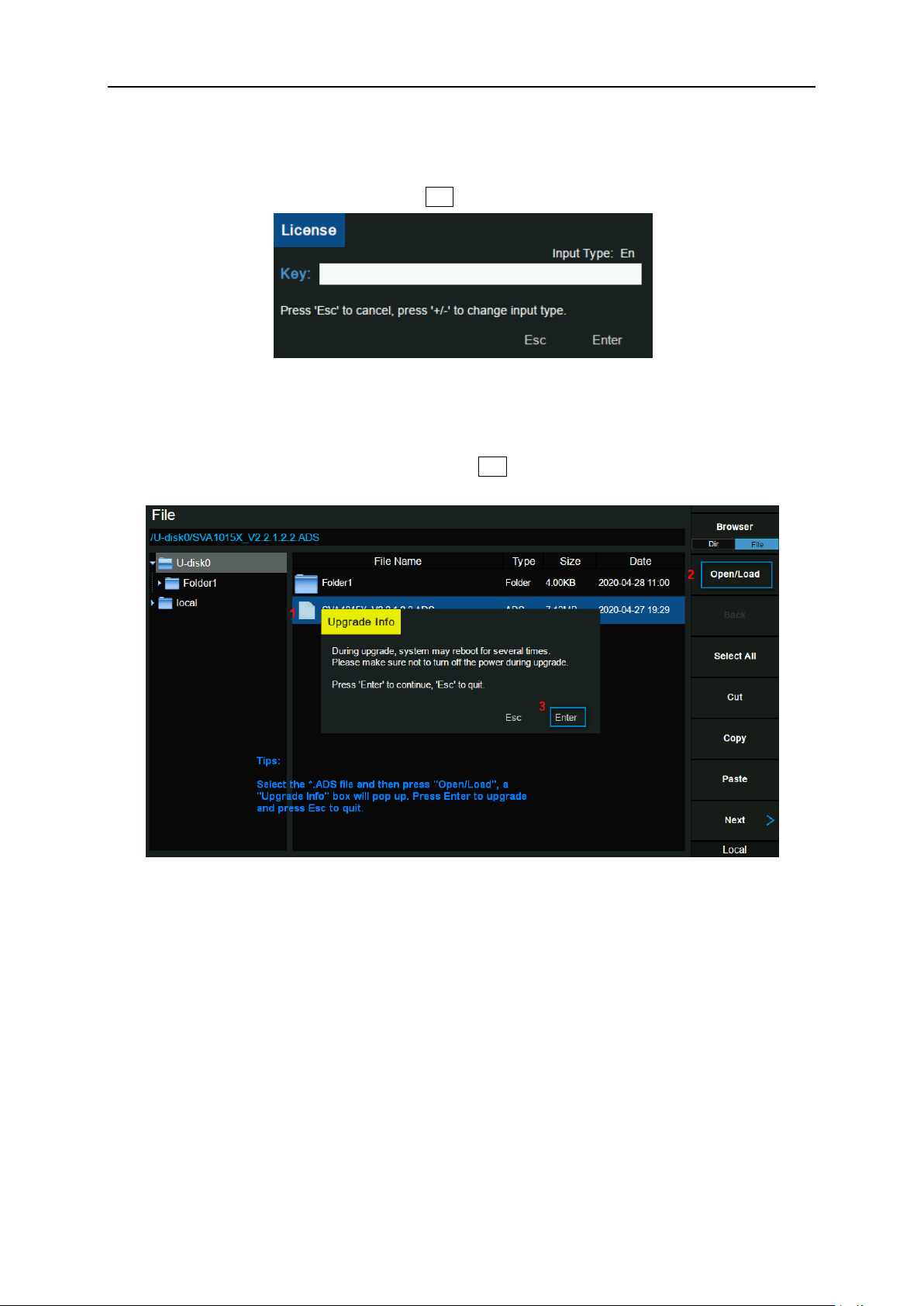
SIGLENT
4.1.5.2 Load Option
Press “Load Option” and then enter the sequence code in the pup-up box to load the options. Options
can also be loaded by loading License files in File ->”Open/Load”.
Figure 4-3 Load Option
4.1.5.3 Firmware Update
Press “Firmware Update” and you will enter into the File menu. Then you can select *.ADS file from
memory to upgrade firmware. After firmware upgrade, the machine will restart.
Figure 4-4 Firmware Update
4.1.5.4 System Message
Display system alarms and warnings.
4.1.6 Date and Time
Set system time, and the display status and display format of system time. System time can be set to
"ymd", "mdy" or "dmy" formats.
System time is displayed in "ymd" format in the middle of the status bar by default.
SSA3000X Plus User Manual 75
Page 94
SIGLENT
Parameter
Explanation
Default
30%
Range
0 ~ 100%
Unit
None
Knob Step
1%
Direction Key Step
1%
4.1.7 Self Test
1. Screen Test
Test whether the screen has any pixel defects by displaying five colors: White, Red, Green, Blue and
Black. Press ‘Preset’ key to switch the screen color and press ‘←’ key to exit the test.
2. Keyboard Test
Enter the keyboard test interface. Press the function keys at the front panel one-by-one and observe
whether the corresponding key is checked. If not, an error may have occurred in that key. To exit the
test, press ‘←’ four times.
3. LCD Test
If the keys at the front panel are transparent, when the key is pressed, the corresponding backlight will
turn on when testing it.
4. Touch Test
Test whether the touch screen has any defects by touching the test button at specific spots on screen.
4.2 Display
Control the display of the screen.
4.2.1 Grid Brightness
Control the display grid brightness.
Table 4-1 Grid brightness
4.2.2 Screenshot
Toggle between normal and inverse color for images of the display saved to storage.
The color of traces is not inversed in inverse mode.
76 SSA3000X Plus User Manual
Page 95
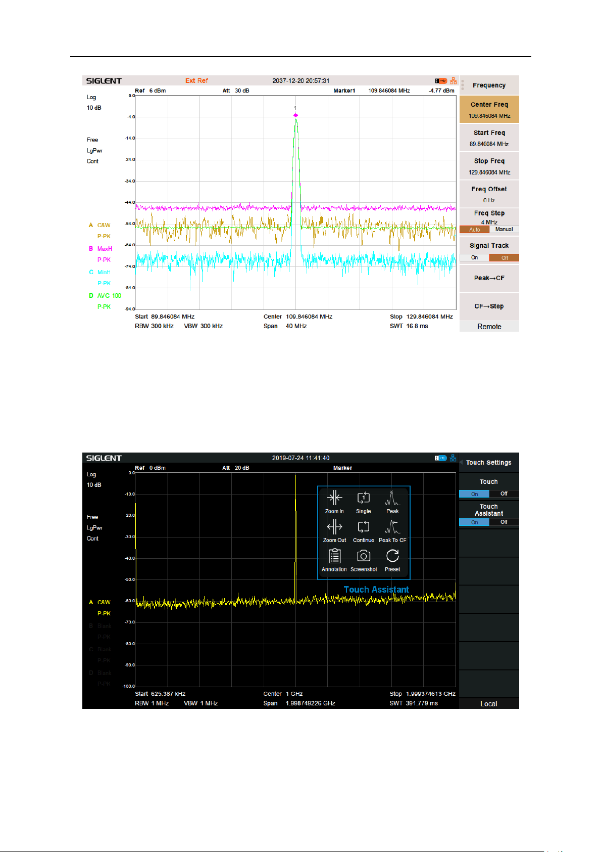
Figure 4-5 Inverse color Screenshot
SIGLENT
4.2.3 Touch Settings
You can turn on or off touch screen settings and touch assistance.
Touch assistance can be moved to any position on the screen after the touch screen settings are
opened.
Figure 4-6 Touch assistance
SSA3000X Plus User Manual 77
Page 96
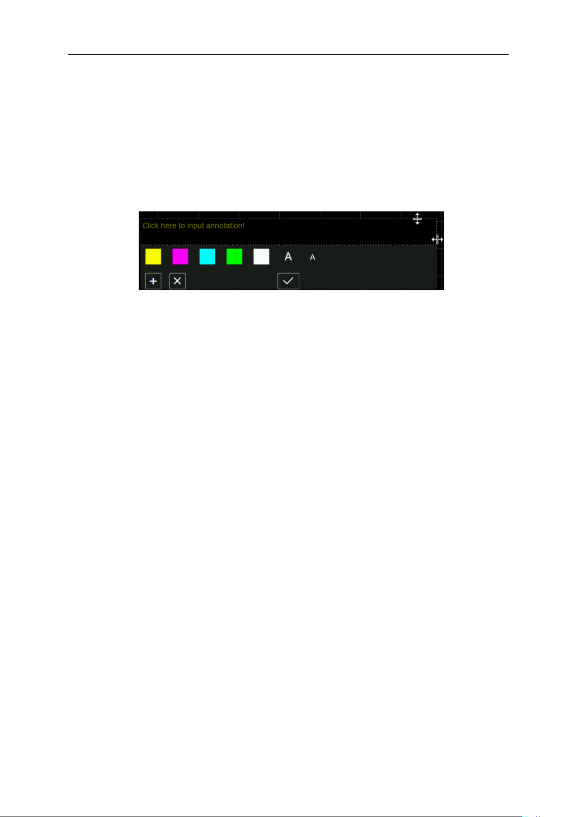
SIGLENT
4.2.4 Power Saving
After setting the power saving, the screen backlight can be turned off when there is neither touch
screen operation nor button operation for a certain period of time. The screen backlight will be turned
on after a touch screen operation or button operation.
4.2.5 Annotation
If turn on the annotation function, you can add annotations on the screen.
Figure 4-7 Annotation
Typical operation sequence is:
Turn on the annotation function: you could activate the annotation function in the Display menu, or
toggle the status of the function using the touch assistant.
Edit text: Click the input area to invoke the virtual keyboard. Use the virtual keyboard or the keys in
the Edit area on the front panel to enter text. During the editing, you could change the color and
size of the text using the color label and font size label respectively. Moreover, you could change
the size of the input area by dragging the two-way arrows on the top and right.
(Optional) Add or delete annotation by clicking the plus sign button and cross sign button. You
could add as many as ten annotations. When you delete the last one, it was not really deleted. In
fact, the annotation function is turned off.
Finish editing: click Enter or Esc button on the virtual keyboard to close the keyboard. Now you
could click in the blank space of the annotation widget and drag it to any places on the screen.
Click the tick button, only the text would be visible and an annotation is successfully added.
If you want to change one of the annotations, click the text and you could repeat the operation above.
Notice that if you change the mode of the analyzer or shut off the analyzer, all the annotations would be
removed. Toggling the status of the annotation function won’t do that, however.
4.2.6 Display Line
Open or Close Display Line or move the location. The display line can be used as a reference for
reading.
78 SSA3000X Plus User Manual
Page 97
SIGLENT
Parameter
Explanation
Default
0 dBm
Range
REF Level + REF Offset – 10*Scale/Div ~ REF Level + ref Offset
Unit
dBm
Knob Step
1
Direction Key Step
Scale/Div
Table 4-2 Display Line
4.3 File
4.3.1 Browser
Browser type including “Dir” and “File”,
Dir: When selected, use the knob or direction keys to change the highlighted directory.
File: When selected, use the knob or direction keys to switch among files or sub-folders under the
current directory.
4.3.2 Open/Load
Open the selected folder or load the selected file.
4.3.3 Back
If there is a previous directory, return to it.
4.3.4 View Type
Select the type of file to be browsed. Include: “All Type”, “STA”, “TRC”, “COR”, “CSV”, “LIM”, “PIC”
(JPG /BMP /PNG).
4.3.5 Save Type
Select the type of file to be saved. The corresponding storage data of various types of files are:
1. STA(Status)
STA files can be used to save and recall the instrument configuration. They are saved in ASCII format,
which can be read by humans.
2. TRC(Trace)
TRC files store the active (visible) trace data and scaling factors that were in place when the data was
saved. They are saved in ASCII format, which can be read by humans.
Note: When you first recall trace files, the instrument will adjust the display parameters (horizontal and
vertical scaling, for example) to match the settings used during data collection. The trace data will not
SSA3000X Plus User Manual 79
Page 98

SIGLENT
change, even if you adjust the parameters.
3. COR(Correction)
COR files store the data used to mathematically adjust the displayed input signal based on external
factors (Cable loss, Amplifier/Antenna gain, etc.). They are saved in ASCII format, which can be read
by humans.
4. CSV(Comma-Separated Variable)
CSV files store instrument configuration (scaling, units, etc.) and raw data (amplitude and frequency
values) in ASCII format, commonly viewed in spreadsheet programs like Microsoft® Excel®. This file
type can be read by humans
5. LIM(limit)
LIM files store the line or point data used to configure and display lines used for visual indication of a
user-defined limit. They are saved in ASCII format, which can be read by humans.
6. BMP(Bitmap) /JPG(JPEG) /PNG
Picture files capture the display of the instrument (screenshot) as an image file. All of the details of the
display are captured exactly. What you see on the display is in the file. These are readable using image
programs like Microsoft® Paint®.
4.3.6 Save
Save file in current directory, the file type is set in ‘Save Type’.
If there is an external memory, it will be saved to the external memory first.
Also used to set the save type of the Save shortcut, which can be used to quickly save the files.
4.3.7 Create Folder
Create a new folder in current directory.
4.3.8 Operate
1. Browser
Browse files or directories; use the knob or direction keys to select the corresponding item.
2. Open/Load
Open the selected folder or load the selected file.
3. Back
Return to previous directory
4. Select All
80 SSA3000X Plus User Manual
Page 99
Select all the files and folders in the current directory.
Parameter
Default
Frequency
Center Freq
750 MHz
Start Freq
0 Hz
Stop Freq
1.5 GHz
Freq Offset
0 Hz
Freq Step
Auto, Span /10
Signal Track
Off
Span
Span
1.5 GHz
X Scale
Linear
5. Cut
Cut the Selected file or folder, and delete the primary one after paste.
6. Copy
Copy the Selected file or folder for paste.
7. Paste
Paste the file cut or copied before into the current.
8. Delete
Delete the selected file or directory.
9. Rename
Rename the selected file or folder.
SIGLENT
4.4 Shortcut Key
4.4.1 Preset
Recall the preset setting and restore the analyzer to a specified status.
Press System ->”Pwr On/Preset” ->”Preset” to select “Def”, “Last” or “User”.
Press Preset to load the factory settings listed in the following table (except items marked with “**”)
or Last settings or User-defined settings.
Different modes have their own Presets. The following table shows the initial default state of the
Spectrum Analyzer Mode.
Table 4-3 Default Preset of Spectrum Analyzer Mode
SSA3000X Plus User Manual 81
Page 100

SIGLENT
Amplitude
Ref Level
0 dBm
Attenuator
Auto, 20 dB
Preamp
Off
Units
dBm
Scale/Div
10 dB
Scale Type
Log
Ref Offset
0 dBm
Corrections
Off
RF Input
50 Ω
Apply Corrections
Off
Correction x
Off
Correction x data
Null
BW
RBW
Auto, 1MHz
VBW
Auto, 1MHz
VBW/RBW
1
Avg Type
Log Pwr
Filter
Gauss
Sweep
Sweep Time
Auto
Sweep Rule
Speed
Sweep
Continue
Sweep Mode
Auto
Numbers
1
QPD Dwell Time
50 ms
Trig
Trigger Type
Free Run
Video Trigger
0 dBm
External Trigger
Rising
TG
TG
Off
TG Level
-20 dBm
TG Lvl Offset
0 dB
Normalize
Off
Norm Ref Lvl
0 dB
Norm Ref Pos
100%
Ref Trace
Blank
Trace
Select Trace
A
Trace Type of Trace A
Clear Write
82 SSA3000X Plus User Manual
 Loading...