

Page 1
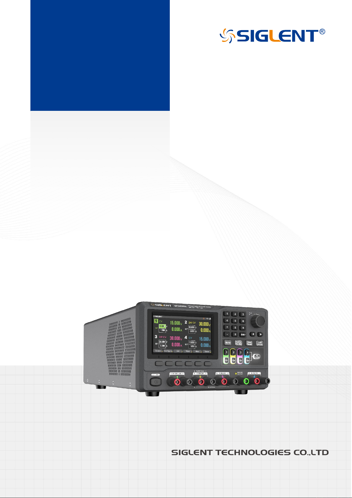
SPD4000X Series
Programmable Linear
DC Power Supply
QuickStart
EN01A
Page 2

Page 3

Copyright and Statement
Copyright
SIGLENT TECHNOLOGIES CO., LTD
. All rights reserved.
Trademark Information
SIGLENT
is registered trademark of
SIGLENT TECHNOLOGIES CO., LTD
.
Statement
SIGLENT
SIGLENT
Information in this publication replaces all previous corresponding published material.
Contents in this manual are not allowed to be copied, extracted or translated in any form or by any means
without
products are protected by patent laws in and outside of the P.R. China.
reserves the rights to change the specification and price.
SIGLENT
's permission.
Product Certification
SIGLENT
standards, and further certified that this product meets the relevant standards of other international
standards organization members.
certified that this product meets China's national product standards and industry product
Contact Us
SIGLENT TECHNOLOGIES CO., LTD.
Address: Blog No.4 & No.5, Antongda Industrial Zone, 3rd Liuxian Road,
Bao'an District, Shenzhen, 518101, China.
Tel: 400-878-0807
E-mail: [email protected]
Http://www.siglent.com
SPD4000X Series Quick Start 1
Page 4

Contents
Copyright and Statement ........................................................................................................ 1
General Safety Summary ....................................................................................................... 3
Safety Terms and Symbols ..................................................................................................... 4
General Care and Cleaning .................................................................................................... 5
General Inspection ................................................................................................................. 5
Considerations........................................................................................................................ 6
Mechanical Dimensions .......................................................................................................... 7
Preparation Before Use ................................................................ ................................ .......... 8
Panel Introduction ................................................................................................................... 9
User Interface ........................................................................................................................ 11
Basic Operation .................................................................................................................... 13
Remote Control .................................................................................................................... 20
More Information .................................................................................................................. 20
2 SPD4000X Series Quick Start
Page 5

General Safety Summary
Please review the following safety precautions carefully to avoid personal injury or damage to this product
or any product connected to it. To prevent potential danger, please use the instrument as specified.
Use proper power cord
Only the power cord designed for the instrument and authorized by local country could be used.
Power supply
AC Input Voltages: 100V/120V/220V/230V±10%, 50/60Hz.
Use proper fuse
The fuse type of SPD4323X: 100V/120V: T6.3A/250V; 220V/230V: T3.15A/250V.
The fuse type of SPD4121X: 100V/120V: T10A/250V; 220V/230V: T3.15A/250V.
The fuse type of SPD4306X: 100V/120V: T10A/250V; 220V/230V: T6.3A/250V.
Make sure to use the correct type of fuse before turning on the instrument.
Do not connect the power cord before replacing the fuse.
Find out the reason why the fuse burned out before replacing the fuse.
Ground the instrument
The instrument is grounded through the protective earth conductor of the power cord. To avoid electric
shock, the grounding conductor must be connected to the earth. Make sure that the instrument is properly
grounded before any inputs or outputs.
Observe all terminal ratings
To avoid fire or electric shock, please observe all ratings and symbols on the instrument. Read this guide
carefully to know more details about the ratings before connection.
Keep proper ventilation
Inadequate ventilation may cause an increase of temperature, which will lead to further damage. Please
keep proper ventilation and check the fan and air-vents regularly when using the instrument.
Do not operate when you suspect that the product is malfunctioning
If you suspect that this product is damaged, please have it inspected by qualified maintenance personnel.
SPD4000X Series Quick Start 3
Page 6
DANGER
Indicates direct injury or hazard that may happen.
WARNING
Indicates potential injury or hazard that may happen.
CAUTION
Indicates potential damage to the instrument or other property that may happen.
Hazardous
Voltage
Warning
Protective
Earth Ground
Earth
Ground
Power
Switch
Operate condition
Location: indoor, no strong light, almost no Interfering pollution
Comparative humidity: ≤ 80%
Altitude: ≤ 2000m
Temperature: 0℃ to 40℃
Do not operate in an explosive atmosphere
To avoid personal injury or damage to instrument, please do not operate in an explosive atmosphere.
Keep surface of the product clean and dry
To avoid dust or moisture in the air influence the performance of the instrument, please keep surface of the
product clean and dry.
Safety Terms and Symbols
Terms may appear on the product:
Symbols may appear on the product:
4 SPD4000X Series Quick Start
Page 7

General Care and Cleaning
Care:
Do not store or leave the instrument in direct sunshine for extended periods.
Cleaning:
Please perform the following steps to clean the instrument and joints.
1. Clean the loose dust on the outside of the instrument and joints with a soft cloth.
2. Disconnect the instrument from all power sources and then clean it with a soft damp cloth. For more
thorough cleaning, a 75% isopropanol water solvent can be used.
To avoid damage to the surface of the instrument and joints, please do not use any corrosive liquid or
chemical cleansers.
Make sure that the instrument is completely dry before restarting it to avoid potential short circuits or
personal injury.
General Inspection
Please check the instrument according to the following steps.
Inspect the shipping container
Keep the damaged shipping container or cushioning material until the contents of the shipment have been
completely checked and the instrument has passed both electrical and mechanical tests.
The consigner or carrier will be responsible for damages to the instrument resulting from shipment.
SIGLENT
If there are instruments found damaged, defective or have failed any electrical and/or mechanical tests,
please contact
Please check the accessories according to the packing list. If the accessories are incomplete or damaged,
please contact your
would not provide free maintenance or replacement.
Inspect the instrument
SIGLENT
.
Check the accessories
SIGLENT
sales representative.
SPD4000X Series Quick Start 5
Page 8
Warning
To switch to the wanted power voltage, please disconnect the power cord first.
Warning
To avoid electric shock, please make sure that the instrument is grounded correctly.
Considerations
To ensure that the instrument can work normally, please conduct necessary inspection before using it.
Input Power Requirement
The SPD4000X allows a 50Hz/60Hz frequency, and four levels of AC power: 100V/120V/220V/230V±10%.
You can select wanted power voltage with the "DIP Switch" at the rear panel according to the actual demand.
Electrical Check
Please use the power cord provided as accessory and connects the instrument to AC power. Check the
power as the following steps.
1. Connect the power supply
2. Turn on the power switch
Turn on the power switch to enter boot interface, and system return to the default settings after a while.
6 SPD4000X Series Quick Start
Page 9
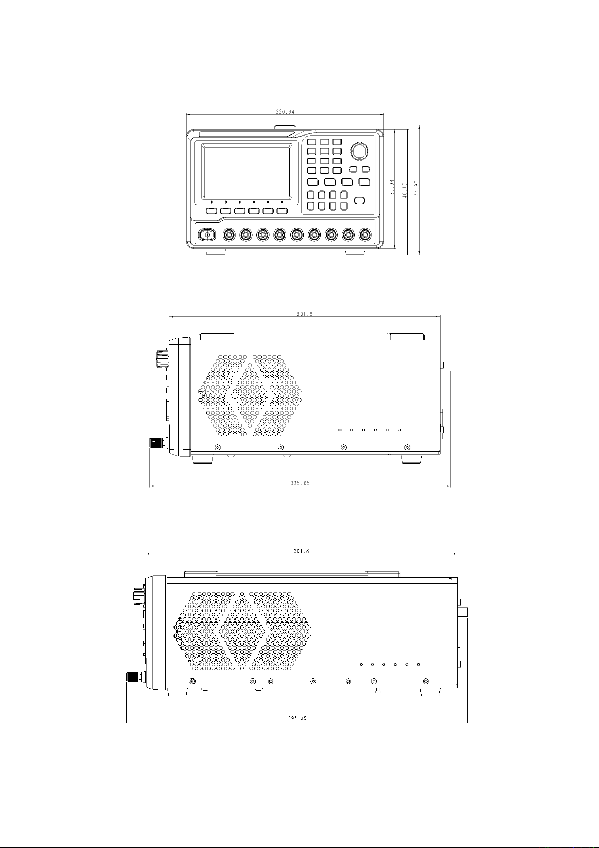
Mechanical Dimensions
Front View
Right View (SPD4323X)
Right View (SPD4121X/SPD4306X)
SPD4000X Series Quick Start 7
Page 10

Preparation Before Use
Connect AC Power
The SPD4000X allows a 50Hz/60Hz frequency, and four levels of AC power: 100V/120V/220V/230V±10%.
Please use the power cord provided as accessory and connects the instrument to AC power. Before
powering on, please confirm that the fuse is working properly.
Output Check
The output check includes voltage check in condition of all channels with no load and current check in
condition of short circuit so as to make sure that the instrument correctly responds to operation of the front
panel.
Voltage output check:
1. Within no load, turn on the power, and make sure the setting current values of all channels are not
zero.
2. Turn on CH1/CH2/CH3/CH4 and the instrument work in constant voltage mode. Check whether the
voltage value could be changed from 0V to rated output voltage.
Current output check:
1. Turn on the power, and make sure the setting voltage values of all channels are not zero.
2. Use an insulated wire to connect the positive and negative terminal of CH1/CH2/CH3/CH4.
3. Turn on CH1/CH2/CH3/CH4 and the instrument work in constant current mode. Check whether the
current value could be changed from 0A to rated output current.
8 SPD4000X Series Quick Start
Page 11
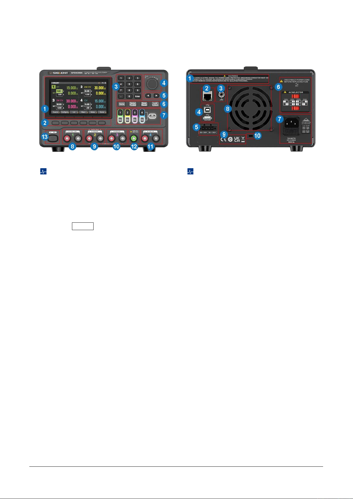
Panel Introduction
Front Panel
1. Display area
2. Menu buttons. Access the display
interface menu
3. Numeric keypad. Enter a value and
press Enter to confirm
4. Knob. Press the knob can quickly move
the cursor position, rotate the knob can
increase or decrease the value
5. Right/left direction button. Press the
button to move the cursor around
6. Shortcut function buttons
7. Channel control buttons
8. CH1 output terminals
9. CH2 output terminals
10. CH3 output terminals
11. CH4 output terminals
12. Ground terminal
13. Power switch
Rear Panel
1. Warning message
2. LAN port
3. Ground port
4. USB ports
5. CH2/3 sense port
6. The DIP switch of the AC power and its
identification
7. AC power socket and AC input voltage
description
8. Fan vents
9. Certification mark
10. Device lock
SPD4000X Series Quick Start 9
Page 12
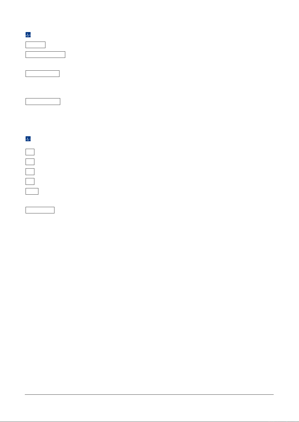
Shortcut Function Buttons
Home : Press this button to directly return to the main interface.
Parallel/Series : Set CH2/3 to parallel/series mode. The parallel or series logo of the corresponding mode
is displayed on the display area at the same time.
Save/Recall : Perform save/recall operations on internal storage or external U disk. When pressing and
holding this button for more than 3 seconds, the device will take a screenshot and save it to the U disk
connected to the device.
Lock/Unlock : Enable/disable the lock function. Short press the button to enable lock function, long press
to disable it, and the device will be automatically locked when remotely controlled.
Channel Control Buttons
1 : Press the button to select CH1 as the current channel.
2 : Press the button to select CH2 as the current channel.
3 : Press the button to select CH3 as the current channel.
4 : Press the button to select CH4 as the current channel.
On : Press the button to turn on/off the output of current channel. When this button is illuminated, it
indicates that the channel is in an open state.
All On/Off : Press the button to turn on/off all the channels. When this button is illuminated, it indicates
that all channels are in an open state.
10 SPD4000X Series Quick Start
Page 13
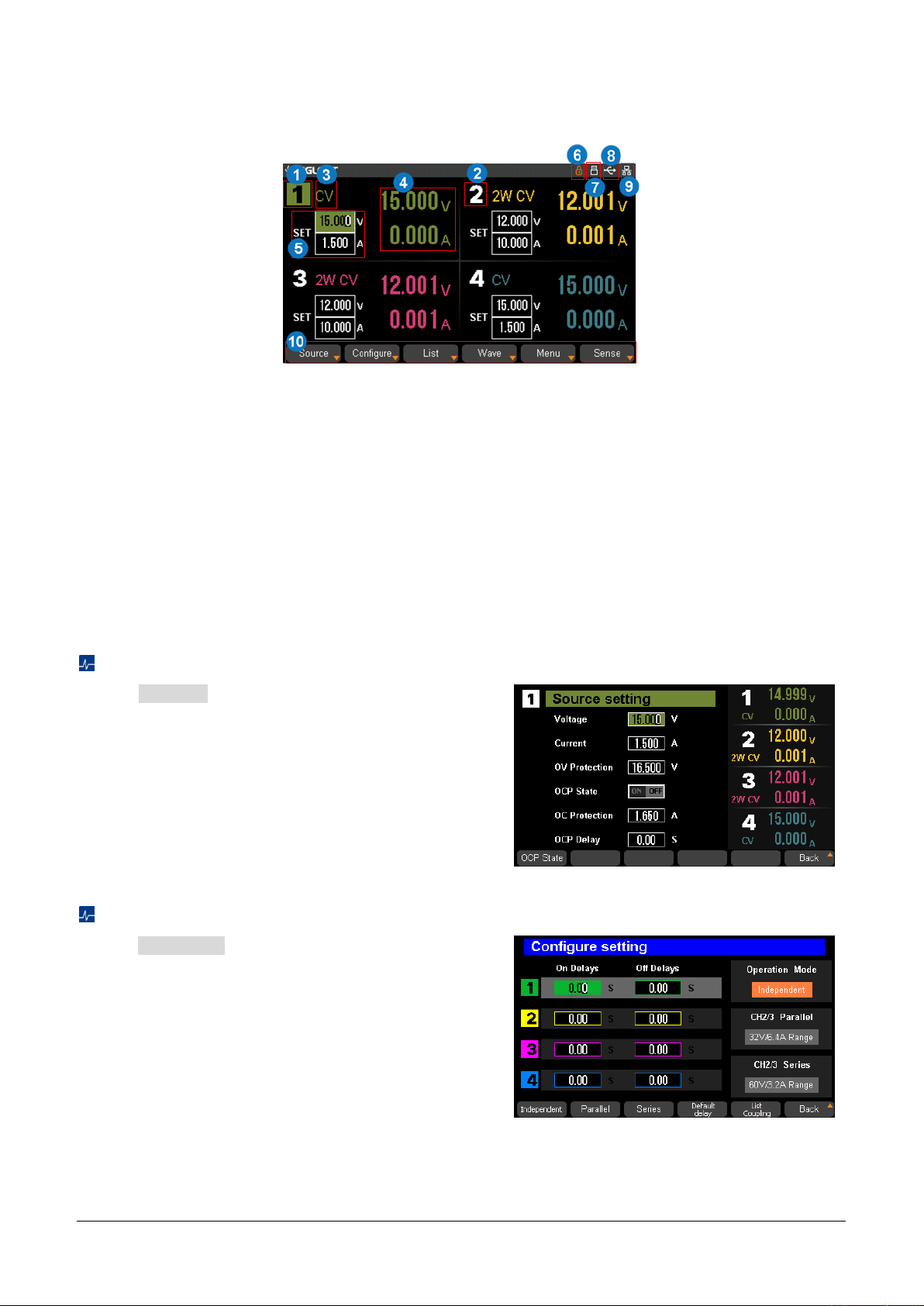
User Interface
1. Channel logo.
2. CH2/CH3 working state: 2W or 4W.
3. Operating mode logo. The corresponding logo
will display when working in CV or CC mode.
4. Output value. Display the current actual output
voltage and current.
5. Output settings. Display the current output
voltage and current settings, which can be
adjusted using the numeric keypad or turning
the knob on the front of the panel.
6. Lock logo. It will display when the
instrument is currently locked.
7. U disk logo. It will display when there is a
U-disk connection.
8. USB logo. It will display when there is a
USB connection.
9. LAN logo. It will display when there is a
LAN connection.
10. Front panel menu. Contains Source,
Configure, List, Wave, Menu, and Sense.
Press Source corresponding menu button on the
panel to enter the source setting interface, where you
can set the output voltage, output current, overvoltage
protection (OVP), overcurrent protection (OCP), etc.
Press Configure corresponding menu button on the
panel to enter the configure setting interface. The
following functions can be set:
Delays: Set the delay time for turning on/off the
output. 0-3600s can be set with a resolution of
0.01s
Operation mode: Set CH2/3 to
independent/parallel/series mode
Default delay: Set the delay time to zero after
confirming the setting in the pop-up window
List coupling
Source
Configure
SPD4000X Series Quick Start 11
Page 14
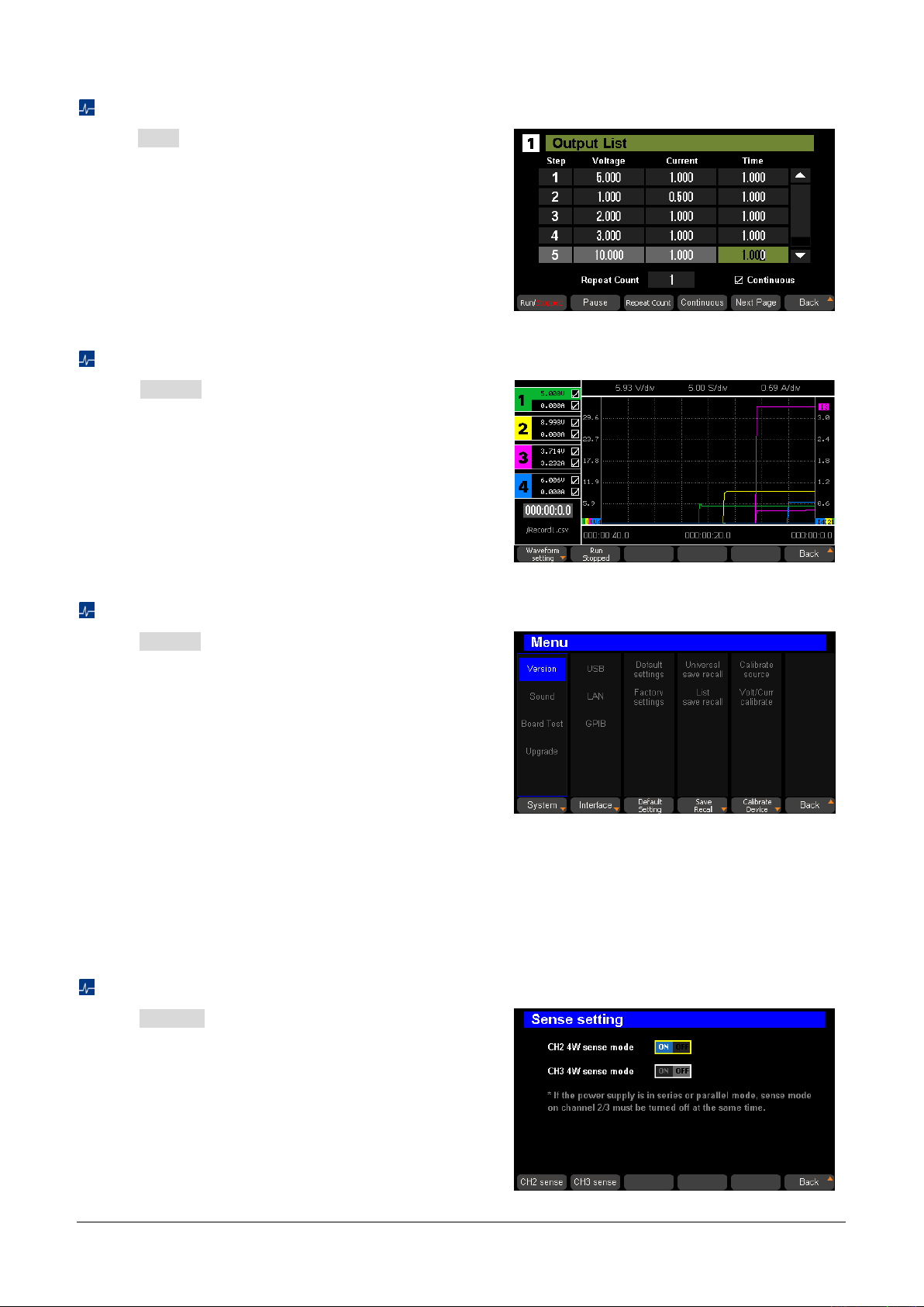
Press List corresponding menu button on the panel
to enter the list setting interface and set the list.
Press Wave corresponding menu button on the
panel to enter the list setting interface, where you can
observe the real-time change of output parameters
(voltage/current).
Press Menu corresponding menu button on the
panel to enter the menu interface. The following items
can be viewed or set:
System: Can perform operations such as viewing
version information, sound settings, board test,
upgrade.
Interface: USB, LAN, GPIB can be viewed or set.
Default Setting: Include default settings and
factory settings.
Save Recall: Include universal save/recall and list
save/recall.
Calibrate Device: Include calibrate source and
Volt/Curr calibrate.
Press Sense corresponding menu button on the
panel to enter the sense settings interface and set
CH2/CH3 4W sense mode to on or off.
List
Wave
Menu
Sense
12 SPD4000X Series Quick Start
Page 15

Basic Operation
Output Mode Setting
The SPD4000X has four sets of independently adjustable output sources, each output source supports
constant voltage mode and constant current mode. The CH1/CH4 of the SPD4000X have only one
independent output mode, when the CH2/CH3 have three output modes: independent, parallel and series.
In the independent mode, the output current and voltage are controlled respectively. In the parallel mode,
the current value is twice that of the single channel. In the series mode, the voltage value is twice that of
the single channel. When CH2 and CH3 are operating in independent mode, the 4W sense mode can be
activated.
Constant Voltage/Current Mode
The SPD4000X supports constant voltage and constant current mode. If the output load impedance value
is greater than the value obtained by dividing the voltage setting by the current setting, the instrument will
operate in constant voltage mode (CV). If the output load impedance is less than the value obtained by
dividing the voltage setting by the current setting, the instrument will operate in constant current mode (CC).
•
In constant voltage mode, the current value is less than the set value, and the voltage value is controlled
through the front panel. The user interface will display CV logo at this moment, and the voltage value
is maintained at the set value. It will return to constant current mode when the output current value
reaches the set value.
•
In constant current mode, the current value is rated and controlled through the front panel. The user
interface displays the CC logo, and the current is maintained at the set value. At this point, the voltage
value is under rating. It will return to constant voltage mode when the output current value is less than
the set value.
Independent Output Mode
CH1~CH4 are working in the independent mode, at the same time, they are insulated from the ground. The
withstand voltage of the output terminals to the ground is ± 240VDC.
Setting method:
1. Press Configure corresponding menu button on the panel to enter the configure setting interface.
2. Press Independent corresponding menu button on the panel, and the Independent under
Operation Mode of the interface lights up, indicating that independent mode is selected. At this point,
the Parallel/Series button light is off, and there is no serial or parallel logo on the user interface.
3. Connect the load to the terminals on the front panel: CH1 +/-, CH2 +/-, CH3 +/-, CH4 +/-.
4. Set voltage and current value of CH1/CH2/CH3/CH4:
SPD4000X Series Quick Start 13
Page 16

a) Press 1 / 2 / 3 / 4 button to select the wanted channel
b) Move the cursor through left/right direction button to select the wanted parameter (voltage, current)
c) Use the numeric keypad or knob to set the required value and then press Enter button to
complete the value setting
5. Turn on the output: Press ON button to turn on the output, the corresponding channel indicator light
activates immediately, and "CC" or "CV" logo is shown on the current interface.
CH2/CH3 Parallel Mode
In the parallel mode, the current value is twice as much as the single channel. CH2/3 are linked internally
into one channel which is controlled by CH2, and CH2 reads the parallel voltage and current values.
Setting method:
1. Press Configure corresponding menu button on the panel to enter the configure setting interface.
2. Press Parallel corresponding menu button on the panel to enable CH2/3 parallel mode, and the
range of CH2/CH3 parallel voltage/current values under CH2/3 Parallel light up, indicating that
parallel mode is selected. At this point, the Parallel/Series button light is on, and there is "CH2/3
Parallel" logo on the user interface.
3. Connect the load to the terminals on the front panel: CH2 +/-.
4. Set voltage and current value.
a) Press 2 button to select the channel 2
b) Move the cursor through left/right direction button to select the wanted parameter (voltage, current)
c) Use the numeric keypad or knob to set the required value and press Enter to complete the
value setting
5. Press On button corresponding CH2 to turn on the output.
CH2/CH3 Series Mode
In the series mode, the voltage value is twice compared with that of single channel. CH2/3 are linked
internally into one channel which is controlled by CH2, and CH2 reads the parallel voltage and current
values.
Setting method:
1. Press Configure corresponding menu button on the panel to enter the configure setting interface.
2. Press Series corresponding menu button on the panel to enable CH2/3 series mode, and the range
of CH2/CH3 series voltage/current values under CH2/3 Series light up, indicating that series mode
is selected. At this point, the Parallel/Series button light is on, and there is "CH2/3 Series" logo on
the user interface.
3. Connect the load to the terminals on the front panel: CH2+ & CH3-.
14 SPD4000X Series Quick Start
Page 17

4. Set voltage and current value.
a) Press 2 button to select the channel 2
b) Move the cursor through left/right direction button to select the wanted parameter (voltage, current)
c) Use the numeric keypad or knob to set the required value and press Enter to complete the
value setting
5. Press On button corresponding CH2 to turn on the output.
Note: Users can also use the Parallel/Series button on the front panel to select independent, parallel, or
series modes directly.
4W Sense Mode
Only CH2 and CH3 can activate 4W sense mode, and 4W sense mode is not supported in series or parallel
mode. When 4W sense mode is turned on and the wires are correctly connected, it can automatically
compensate for the voltage drop of the positive and negative output lines, ensuring that the voltage of the
remote device to be tested is equal to the set voltage of the power supply. To use this function, you need
to use the voltage sense connector in the attachment.
Save and Recall
The SPD4000X supports saving the current settings to native internal storage or an external U disk, users
can recall the saved file to restore the settings. If the external mode is selected, the data will be saved in
the external U disk and can be recalled in the recall mode.
Eight group setups can be saved in memory. The contents of the setup file including:
Independent/series/parallel mode
Output voltage/current value
Save/Recall include universal save/recall and list save/recall. The following describes the operation steps
for universal save/recall, with similar steps for list save/recall.
Save Setting
1. Set the state that you wanted.
2. Press Save/Recall button to enter the universal save interface.
SPD4000X Series Quick Start 15
Page 18
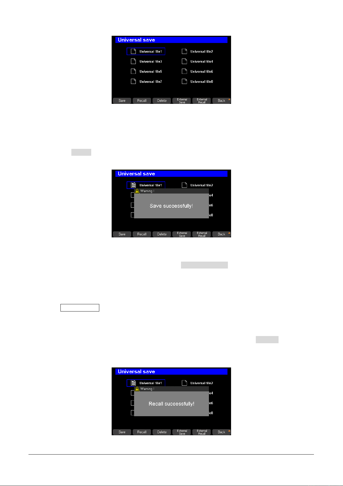
3. You can save the data to native internal storage or an external U disk by following steps.
Save the data to native internal storage:
Press the left/right direction button to select a file saving location (Universal file1 ~ Universal file8), and
press the Save corresponding menu button on the panel to save the current settings. The prompt
window "Save successfully" will pop up when the file is saved successfully.
Save the data to an external U disk:
After connecting a U disk to the SPD4000X, press External Recall corresponding menu button on
the panel,
and the data will be saved in the U disk.
Recall Setting
1. Press Save/Recall button to enter the universal save interface.
2. You can recall the data to native internal storage or an external U disk by following these steps.
Recall the data from native internal storage:
Select the saved file that you want to invoke by left/right direction button. Press Recall
corresponding menu button on the panel to recall the selected file. When the file is recalled
successfully, the prompt window "Save Successfully" will pop up.
16 SPD4000X Series Quick Start
Page 19
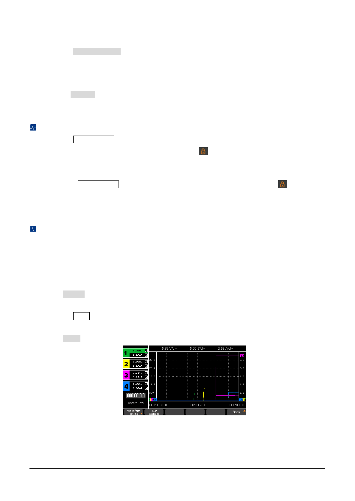
Recall the data from an external U disk:
Press the External Recall corresponding menu button on the panel to recall the selected file to recall
the data stored on an external U disk.
Note: If you want to delete a file that has been saved before, use the left/right direction button to select the
file and press Delete corresponding menu button on the panel to delete it.
Lock Function
1. Press the Lock/Unlock button on any interface to activate the lock function.
2. When the lock function is activated, a graphic symbol appears in the upper right corner of the
interface. At this point, the buttons on the front panel will not function, but the device can be remotely
controlled.
3. Long press Lock/Unlock button to turn off lock function, and the graphic symbol in the upper
right corner of the interface will disappear at the same time.
Waveform Display
SPD4000X can display the changes of the output voltage and current of the channel in real time through
the form of curve plotting.
Specific steps are below:
1. Set channel output parameters.
2. Press Wave corresponding menu button on the panel to enter the waveform display interface.
3. Select the parameter that you want to display the waveform.
4. Press the ON button corresponding to the selected channel to open the channel output, and then
you can observe the real-time change of output parameters (voltage/current).
5. Press Run to save waveform data to the U disk connected to the instrument.
Note: The color of the output parameter waveform curve corresponds to the color of the channel.
SPD4000X Series Quick Start 17
Page 20
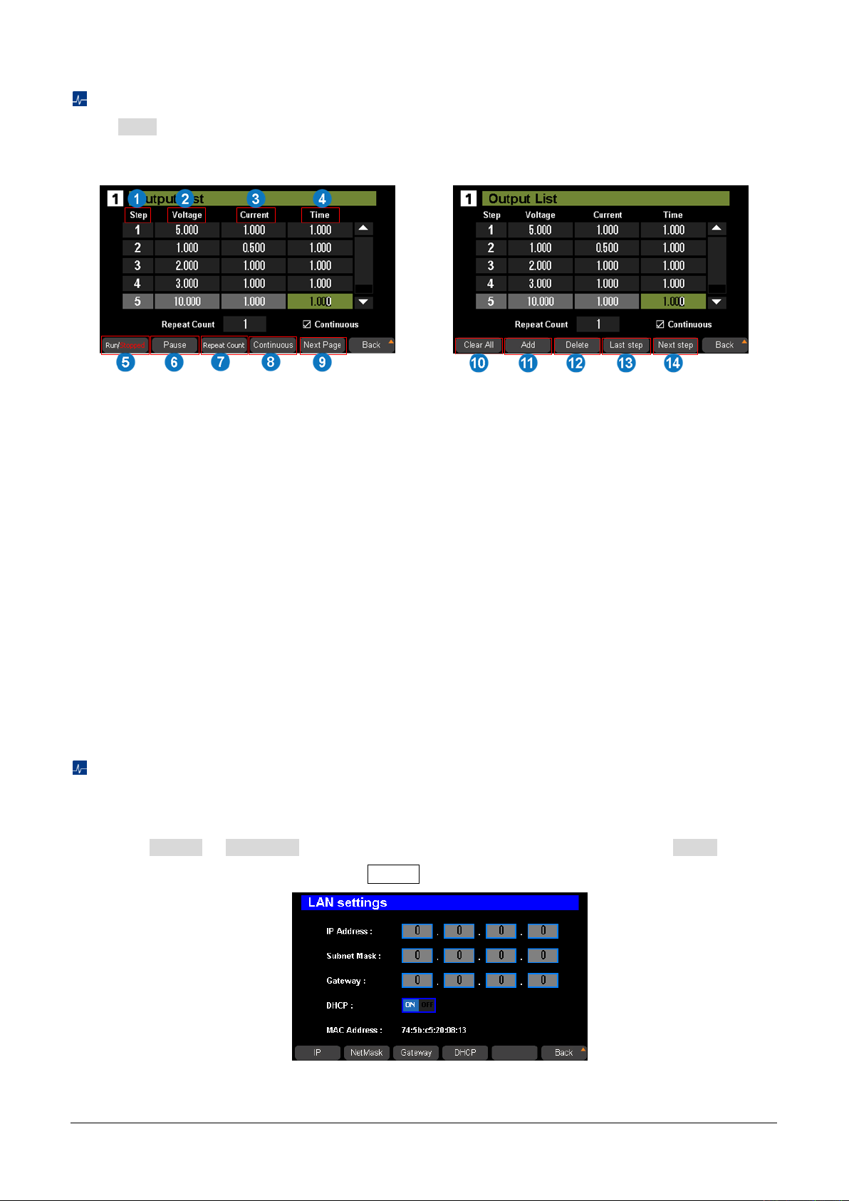
1. Step number
2. Voltage: Set the output voltage corresponding
to the number of steps. Select the number of
steps you want to set and use the numeric
keypad or knob to set the value
3. Current: Set the output current corresponding
to the number of steps. Select the number of
steps you want to set and use the numeric
keypad or knob to set the value
4. Time: Set the running time of the current step
5. Run/Stopped: Run/stopped the list
6. Pause: Pause the list
7. Repeat Court: The maximum is 9999
8. Continuous: Continuous loop the list
9. Next Page: Go to the next page
10. Clear All: Clear all steps in the list after
confirming the setting in the pop-up
window
11. Add: Add a step to the list
12. Delete: Delete the current selected step
in the list
13. Last step: Edit the last step
14. Next Step: Edit the next step
List Setting
Press List corresponding menu button on the panel to enter the output list setting interface and set the
list.
LAN Seting
Setting method:
1. Connect the LAN port on the rear panel of the power supply to the local network using a network cable.
2. Press Menu > Interface corresponding menu button on the panel, and select LAN through
the left/right direction button. Press the Enter button to enter the LAN setting interface.
18 SPD4000X Series Quick Start
Page 21
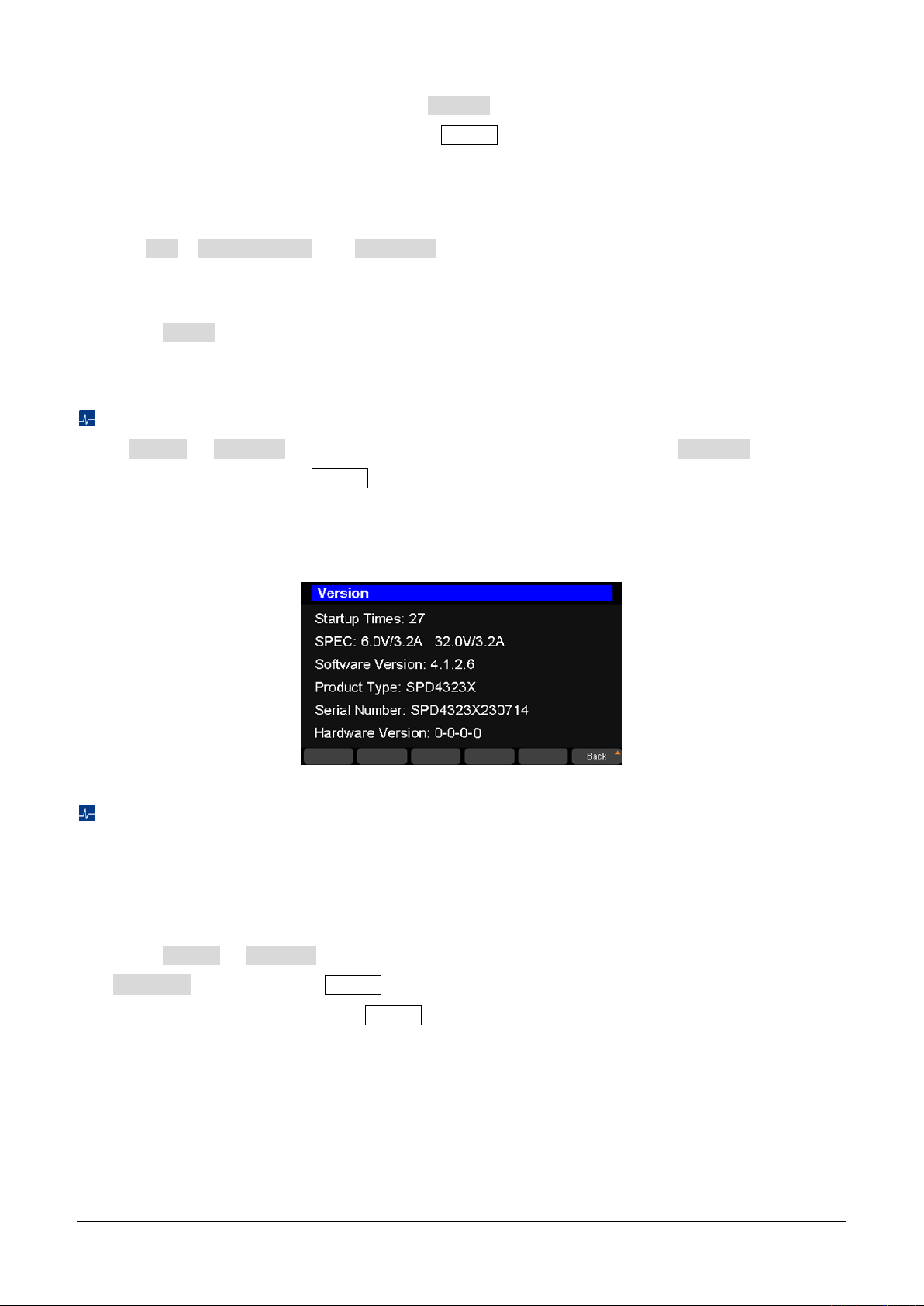
3. Press the right/left direction button or press DHCP corresponding menu button on the panel to keep
the cursor on the DHCP line, and then press Enter button to set DHCP to ON or OFF.
ON: The SPD4000X automatically sets IP address, subnet mask, and gateway based on the
network it is connected to.
OFF: User set the IP address, subnet mask address and gateway address manually by pressing
IP , Subnet Mask and Gateway corresponding menu button on the panel respectively,
and use the numeric keypad or the knob to complete the address setting.
4. Use one of the above two methods to complete the LAN setting.
5. Press Back corresponding menu button on the panel to exit the LAN setting interface and return to
menu interface. Press the button again to return to the main interface.
Version Imformation
Press Menu > System corresponding menu button on the panel to select Version through the
left/right direction button. Press Enter button to enter the version information display interface.
The version information includes: startup times, SPEC, software version, product type, serial number, and
hardware version.
System upgrade
Please follow the steps below to upgrade the firmware:
1. Download the firmware upgrade package from the official website.
2. Copy the .ADS file in the upgrade package to the root directory of the U disk.
3. Insert the U disk into the USB port of the rear panel.
4. Press Menu > System corresponding menu button, use left/right direction button to select
Upgrade , and then press Enter button to confirm the selection.
5. Select the upgrade file and press Enter button to confirm, and the upgrade progress bar will pop
up. The instrument will restart after successful upgrade. Otherwise, the upgrade failure information is
displayed in the pop-up window.
Any operation that interrupts the upgrade process may cause upgrade failure or even render the machine
unable to be restarted. Do not remove the U disk or make any changes to the power supply during the
upgrade process.
SPD4000X Series Quick Start 19
Page 22

Remote Control
Based on the SCPI (Standard Commands for Programmable Instruments) command set, the power supply
supports communication with the computer via USB and LAN to realize remote control. Please refer to the
SPD4000X Series Programmable Linear DC Power Supply user manual for remote control methods,
grammatical conventions, and related SCPI commands.
More Information
You can obtain the instrument information and installation status of all options through system menu, for
more information of this product, please refer to the following manuals (you can also download them from
the
SIGLENT
SPD4000X Series Programmable Linear DC Power Supply user manual:
Provides detailed introductions of the functions of this instrument, as well as detail introductions of the
SCPI commands and programming of this instrument.
SPD4000X Series Programmable Linear DC Power Supply data sheet:
Provides the main characteristics and specifications of this instrument.
web site).
20 SPD4000X Series Quick Start
Page 23

Page 24

Headquarters:
SIGLENT Technologies Co., Ltd
Add: Bldg No.4 & No.5, Antongda Industrial
Zone, 3rd Liuxian Road, Bao'an District,
Shenzhen, 518101, China
Tel: + 86 755 3688 7876
Fax: + 86 755 3359 1582
Email: [email protected]
Website: int.siglent.com
North America:
SIGLENT Technologies America, Inc
6557 Cochran Rd Solon, Ohio 44139
Tel: 440-398-5800
Toll Free: 877-515-5551
Fax: 440-399-1211
Email: [email protected]
Website: www.siglentna.com
Europe:
SIGLENT Technologies Germany GmbH
Add: Staetzlinger Str. 70
86165 Augsburg, Germany
Tel: +49(0)-821-666 0 111 0
Fax: +49(0)-821-666 0 111 22
Email: [email protected]
Website: www.siglenteu.com
Follow us on
Facebook: SiglentTech
 Loading...