

Page 1

User Manual
EN_01A
SHA852A
SHA851A
Spectrum Analyzer
Page 2

Page 3

SHA850A User Manual
www.siglent.com I
Copyright and Declaration
Copyright
SIGLENT TECHNOLOGIES CO., LTD. All Rights Reserved.
Trademark Information
SIGLENT is the registered trademark of SIGLENT TECHNOLOGIES CO., LTD.
Declaration
⚫ SIGLENT products are protected by patent law in and outside of P.R.C.
⚫ SIGLENT reserves the right to modify or change parts of or all the specifications or pricing
policies at company’s sole decision.
⚫ Information in this publication replaces all previously corresponding material.
⚫ Any way of copying, extracting or translating the contents of this manual is not allowed without the
permission of SIGLENT.
Product Certification
SIGLENT guarantees this product conforms to the national and industrial stands in China and other
international stands conformance certification is in progress.
Contact Us
If you have any problem or requirement when using our products, please contact SIGLENT
TECHNOLOGIES CO., LTD
Add : Blog No.4 & No.5, Antongda Industrial Zone, 3rd Liuxian Road, Bao’an District, Shenzhen,
518101, China
Tel : 400-878-0807
E-mail : [email protected]
http://www.siglent.com
Page 4

SHA850A User Manual
II www.siglent.com
General Safety Summary
Carefully read the following safety precautions to avoid any personal injury or damage the instrument
and avoid any products connected to it. To avoid potential hazards, please use the instrument as
specified.
Protection is impaired if used in a manner not specified by the manufacturer.
Precautions for Operation
Before operating this product, special training is required to ensure that the user is physically, mentally
and emotionally healthy and able to use the spectrum & network analyzer, otherwise it may cause
personal injury or material damage. Employers、operators are responsible for selecting suitable
personnel to operate this product.
Before moving or transporting this product. Please read and observe the "Safety Transportation
Matters" chapter.
As with all industrial products, the use of substances that cause allergic reactions such as nickel
cannot generally be ruled out. If you experience an allergic reaction while using this product, please
consult a doctor in time to determine the cause.
Before you perform mechanical or heat treatment or disassemble the spectrum & network analyzer,
please be sure to read and pay special attention to the "Waste Disposal/Environmental Protection"
chapter.
In the event of a fire, this product may release harmful substances (gas, liquids, etc.), causing health
problems. Therefore, appropriate measures must be taken, for example, protective masks and
protective clothing must be worn.
Page 5
SHA850A User Manual
www.siglent.com III
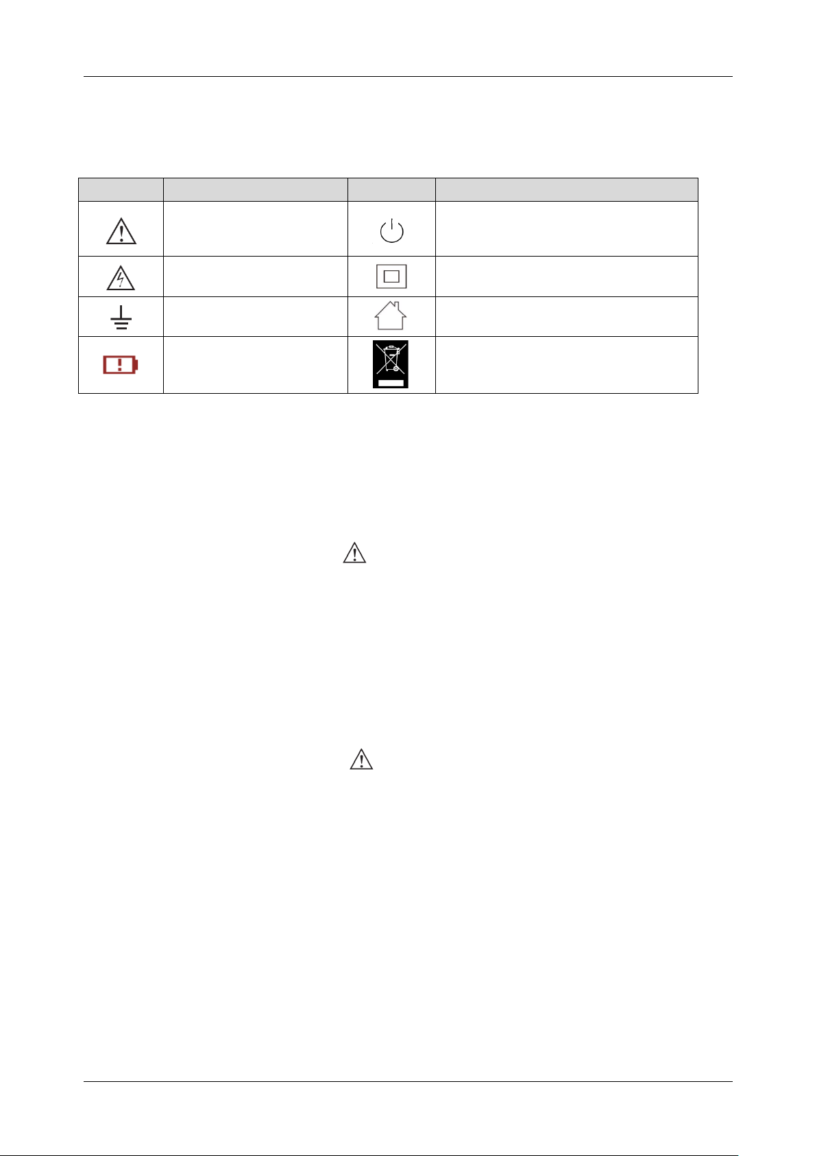
Safety Terms and Symbols
The meaning of symbols
symbol
meaning
symbol
meaning
Warning
Power Switch
Hazardous Voltage
Equipment meeting double
insulation or reinforced insulation
EarthGround
Indoor use only
Lithium battery failure
EU label for separately recycled
electrical and electronic equipment
Cue and its meaning
DANGER : Indicates direct injury or hazards that may happen.
WARNING : Indicates potential injury or hazards that may happen.
CAUTION : Indicates potential damage to the instrument or other property that may happen.
It must be consulted in all cases where is marked, in order to find out the nature of the potential
HAZARDS and any actions which have to be taken to avoid them.
Cue et sa signification
DANGER : Indique des blessures directes ou des dangers qui peuvent survenir.
WARNING : indique des blessures ou des dangers potentiels pouvant survenir.
CAUTION : indique des dommages potentiels à l'instrument ou à d'autres biens pouvant survenir.
Il doit être consulté dans tous les cas où est marqué, afin de connaître la nature des DANGERS
potentiels et les actions à entreprendre pour les éviter.
Page 6

SHA850A User Manual
IV www.siglent.com
Safety Operation Matters
The product can only be operated under the safe conditions and positions specified by the
manufacturer. Do not obstruct the ventilation of the spectrum & network analyzer during use. Failure
to comply with the manufacturer's specifications may result in electric shock, fire, serious personal
injury, or even death. Applicable local safety regulations and accident prevention rules must be
observed in all applications.
When powered by a power adapter, it can only be used indoors.
Do not place the product on surface, vehicle, cabinet or tables that for reasons of weight or stability
are unsuitable for this purpose. When installing the product and fastening it to the article or structures,
always follow the manufacturer's installation instructions. If the installation is not carried out in
accordance with the requirements of the document, it may cause personal injury or even death.
Do not use this product in or near a heat source, and the ambient temperature cannot exceed the
maximum temperature in the document or datasheet
Safety of Electricity
If you ignore the electrical safety methods, electric shock, fire and/or serious personal injury or death
may occur.
Only use the power adapter and battery specified by the manufacturer to power the spectrum &
network analyzer, and the power adapter can only work within its rated input voltage range.
Only the probe specified by the manufacturer can be used for testing. The use of non-manufacturer
probes for testing may result in electric shock accidents.
The user is not allowed to damage the insulation protection layer of the spectrum & network analyzer
and accessories. Doing so may cause electric shock. If an extension cord or terminal block is used for
power supply, it must be checked regularly to ensure safe use.
Before use, please check whether the power cord and probe are damaged. If the power cord and
probe are damaged, please do not continue to use the product.
Do not insert the AC plug of the power adapter into a dusty or dirty socket. Please make sure that the
plug is firmly inserted into the socket, otherwise it may cause fire and/or injury due to sparks.
Do not overload any sockets, extension cords or connectors. Doing so may cause fire or electric
shock.
When the measured voltage Vrms exceeds 30V, you should take appropriate measurement methods
to avoid any danger.
Unless expressly permitted, do not remove the cover or any part of the shell while the product is in
operation. Doing so will expose circuits and components, reduce the overvoltage level of the
measurement, and may cause personal injury, fire, or damage to the spectrum & network analyzer.
Page 7

SHA850A User Manual
www.siglent.com V
Anything that is not designed to be placed on the external interface of this product should not be
placed on the external interface, otherwise it will cause an internal short circuit and/or electric shock,
fire or injury to the spectrum & network analyzer.
Do not place this product in an environment exceeding IP51, otherwise the spectrum & network
analyzer will be damaged.
This product must be used in a dry environment, otherwise it may cause electric shock.
It is forbidden to use this product when condensation has formed or may form inside or on the surface
of this product. For example, when the spectrum & network analyzer moves from a cold environment
to a warm environment, the penetration of water increases the risk of electric shock.
Safety Transportation Matters
SIGLENT Technology provides handbags for the spectrum & network analyzer. For short-distance
transportation under supervision, please make sure that the spectrum & network analyzer is turned off
before putting it in the handbag. For long-distance transportation under unsupervised, please take out
the battery and put it in your handbag.
In order to facilitate the user to hold, SIGLENT Technology has installed a fabric handle on the
spectrum & network analyzer. This handle cannot be used as a focus point to be fixed on
transportation equipment, such as cranes, forklifts, trucks, etc. It is the user's responsibility to fasten
the product firmly to the transportation or lifting tool.
If you use this product in a vehicle, the driver is responsible for driving the vehicle safely and correctly.
The manufacturer is not responsible for any accidents or collisions. Do not use this product in a
moving vehicle to avoid distracting the driver. Use this product appropriately in the vehicle to prevent
injury or other damage in the event of an accident.
Battery Usage
This product contains a rechargeable lithium battery pack. If misused, there is a risk of explosion, fire
and / or serious personal injury, and even death in some cases.
The battery cannot be disassembled or crushed.
The battery or battery pack cannot be exposed to high temperature or fire, and it must be stored in
direct sunlight. Keep the battery clean and dry. Use a dry, clean cloth to clean contaminated
connectors.
The battery or battery pack cannot be short-circuited. Batteries or battery packs should not be stored
in an environment that can easily cause a short circuit, such as boxes and drawers containing metal
debris. The battery pack cannot be taken out of its original packaging before use.
Batteries and battery packs should not be exposed to any mechanical shock that exceeds the
allowable level.
If the battery leaks, do not let the liquid contact the skin or eyes. If contact occurs, wash the contact
Page 8

SHA850A User Manual
VI www.siglent.com
area with plenty of water and seek medical assistance.
The power adapter specified by SIGLENT Technology must be used for charging, otherwise it may
cause a fire or cause personal injury or death.
It must be charged in a well-ventilated room. During the charging process, the spectrum & network
analyzer should not be covered by objects (such as blankets, towels, clothes), which will affect the
heat dissipation effect and cause a serious fire.
Improper battery replacement may cause an explosion. For the reliability and safety of the spectrum &
network analyzer, the battery model specified by SIGLENT Technology must be replaced.
Used batteries and battery packs must be recycled and separated from residual waste. Batteries
contain hazardous waste, and local regulations on waste disposal and recycling must be followed.
Page 9

SHA850A User Manual
www.siglent.com VII
Waste Disposal
The used batteries in the product must not be disposed of together with unsorted municipal waste,
they must be collected separately and placed in designated recycling points.
If the product and its components are mechanically and/or thermally processed in a way beyond the
intended use, hazardous substances may be released. Therefore, this product can only be
disassembled by professional personnel. Improper disassembly may endanger your health. The local
waste disposal regulations must be followed.
Safety Compliance
This section lists the safety standards with which the product complies.
U.S. nationally recognized testing laboratory listing
◼ UL 61010-1:2012/R:2018-11. Safety Requirements for Electrical Equipment for Measurement,
Control, and Laboratory Use – Part 1: General Requirements.
◼ UL 61010-2-030:2018. Safety Requirements for Electrical Equipment for Measurement, Control,
and Laboratory Use – Part2-030: Particular requirements for testing and measuring circuits.
Canadian certification
◼ CAN/CSA-C22.2 No. 61010-1:2012/A1:2018-11. Safety Requirements for Electrical Equipment
for Measurement, Control, and Laboratory Use – Part 1: General Requirements.
◼ CAN/CSA-C22.2 No. 61010-2-030:2018. Safety Requirements for Electrical Equipment for
Measurement, Control, and Laboratory Use – Part 2-030: Particular requirements for testing and
measuring circuits.
Page 10

SHA850A User Manual
VIII www.siglent.com
General Care and Cleaning
Care
Do not store or leave the instrument in direct sunshine for extended periods of time.
To avoid damages to the instrument or probes, please do not expose them to fog, liquid, or solvents.
Cleaning
Please perform the following steps to clean the instrument and probes regularly in accordance with its
operating conditions.
Disconnect the instrument from all power sources and then clean with a soft wet cloth.
Clean the loose dust on the outside of the instrument and probe with a soft cloth. When cleaning the
LCD, take care to avoid scratching it.
To avoid damage to the surface of the instrument and probe, please do not use any corrosive liquid or
chemical cleansers.
Make sure that the instrument is completely dry before restarting it to avoid potential short circuits or
personal injury.
Page 11
SHA850A User Manual
www.siglent.com IX
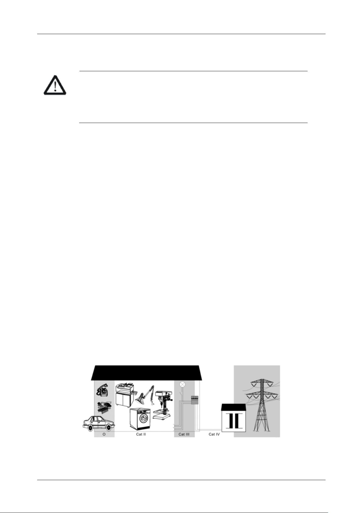
Measurement Category
WARNING
Make sure that no measurement overvoltage reach the product, or else the
operator might expose to danger of electric shock.
Assurez-vous qu'aucune surtension de mesure n'atteigne le produit, sinon
l'opérateur pourrait s'exposer à un risque de choc électrique.
IEC61010-2-030 defines the measurement category to rate the ability of measuring instruments to
withstand short-term transient overvoltage outside of the working voltage. This product and its
accessories can only be used in the environment of the nominal measurement category.
⚫ CAT Ⅰ:
0- An instrument with no rated measurement category is used to measure circuits that are not
directly connected to the mains, such as a circuit board powered by a battery or a secondary
circuit with special protection.
⚫ CAT II:
For measurements installed in buildings, such as junction boxes, circuit breakers, distribution
boards and equipment permanently connected to fixed installations.
⚫ CAT III:
Used for measurements installed in buildings, such as junction boxes, circuit breakers,
distribution boards and equipment that are permanently connected to fixed installations.
⚫ CAT IV:
It is used for measuring at the source of low-voltage devices, such as electricity meters and
primary overcurrent protection devices.
Page 12

SHA850A User Manual
X www.siglent.com
Working Environment
General requirement
Environment
This product is intended for indoor use and should be operated in a clean, dry environment.
It can be stored in an environment with a waterproof/dustproof rating better than IP51.
Temperature
Operating: 0℃ to +40℃
Non-operation:-20℃ to +60℃
Note: Direct sunlight, radiators, and other heat sources should be taken into account when assessing
the ambient temperature.
Humidity
Operating: 85% RH, 40 ℃, 24 hours
Non-operating: 85% RH, 65 ℃, 24 hours
Altitude
Operating: less than 2 km
Non-operation: less than 3 km
Installation (overvoltage) Category
This product is powered by mains conforming to installation (overvoltage) category II.
WARNING
Make sure that no overvoltage (such as that caused by thunderbolt) can
reach the product, or else the operator might expose to danger of electric
shock.
Assurez-vous qu'aucune surtension (comme celle causée par la foudre) ne
peut atteindre le produit, sinon l'opérateur pourrait s'exposer à un risque de
choc électrique.
Installation (overvoltage) Category Definitions
Page 13
SHA850A User Manual
www.siglent.com XI
Installation (overvoltage) category I refers to signal level which is applicable to equipment
measurement terminals connected to the source circuit. In these terminals, precautions are done to
limit the transient voltage to the corresponding low level.
Installation (overvoltage) category II refers to the local power distribution level which is applicable to
equipment connected to the AC line (AC power).
Degree of Pollution
The spectrum & network analyzers may be operated in environments of Pollution Degree II.
Note: Degree of Pollution II refers to a working environment which is dry and non-conductive pollution
occurs. Occasional temporary conductivity caused by condensation is expected.
IP Rating
IP51 (as defined in IEC 60529).
Ventilation Requirement
Please make sure that the air intake and exhaust areas are free from obstructions and have free air.
When using the spectrum & network analyzer in a bench-top or rack setting, provide at least 10 cm
clearance beside, above and behind the instrument for adequate ventilation.
WARNING
Inadequate ventilation may cause temperature increase which would
damage the instrument. So please keep the instrument well ventilated
during operation.
Une ventilation inadéquate peut entraîner une augmentation de la
température qui endommagerait l'instrument. Veuillez donc garder
l'instrument bien ventilé pendant le fonctionnement.
Page 14
SHA850A User Manual
XII www.siglent.com
AC Power Requirement
The power adapter operates with a single-phase, 100 to 240 Vrms (+/-10%) AC power at 50/60 Hz
(+/-5%).
No manual voltage selection is required because the instrument automatically adapts to line voltage.
Depending on the type and number of options and accessories (probes, PC port plug-in, charging
etc.), When powered by adapter, the scope can consume up to 35 W of power.
Note: The power adapter automatically adapts to the AC line input within the following ranges:
Voltage Range:
90 - 264 Vrms
Frequency Range:
47 - 63 Hz
Please use the power cord and adapter provided by the manufacturer. Use of other non-designated
products may cause personal injury.
WARNING
Electrical Shock Hazard!
Use of an adapter or power supply not specified by the manufacturer may
cause personal injury.
Risque de choc électrique !
L'utilisation d'un adaptateur ou d'un bloc d'alimentation non spécifié par le
fabricant peut entraîner des blessures.
To make the spectrum & network analyzer completely power off, unplug the instrument power cord
from the AC socket and remove the battery from the scope.
The battery should be removed from the scope when it is not to be used for an extended period of
time.
Page 15

SHA850A User Manual
www.siglent.com XIII
Maintenance and Services
Only authorized and specially trained personnel can open the spectrum & network analyzer. When
performing maintenance operations on the spectrum & network analyzer, you must remove the power
adapter and make sure that the spectrum & network analyzer is turned off, otherwise it may cause an
internal short circuit of the spectrum & network analyzer.
Adjustment, replacement of parts, maintenance and repair can only be performed by operators
authorized by SIGLENT Technology. Safety-related parts can only be replaced with original parts.
Safety tests must be carried out after replacing part.
Page 16

SHA850A User Manual
XIV www.siglent.com
CONTENTS
COPYRIGHT AND DECLARATION ............................................................................................. I
GENERAL SAFETY SUMMARY ................................................................................................. II
PRECAUTIONS FOR OPERATION ................................................................................................... II
SAFETY TERMS AND SYMBOLS ................................................................................................... III
SAFETY OPERATION MATTERS ................................................................................................... IV
SAFETY OF ELECTRICITY ............................................................................................................ IV
SAFETY TRANSPORTATION MATTERS .......................................................................................... V
BATTERY USAGE ........................................................................................................................ V
WASTE DISPOSAL ..................................................................................................................... VII
SAFETY COMPLIANCE ............................................................................................................... VII
GENERAL CARE AND CLEANING ......................................................................................... VIII
MEASUREMENT CATEGORY ................................................................................................... IX
WORKING ENVIRONMENT ........................................................................................................ X
GENERAL REQUIREMENT ............................................................................................................. X
VENTILATION REQUIREMENT ...................................................................................................... XI
AC POWER REQUIREMENT ........................................................................................................ XII
MAINTENANCE AND SERVICES............................................................................................ XIII
CONTENTS .............................................................................................................................. XIV
1 QUICK START .................................................................................................................. 1
1.1 GENERAL INSPECTION .................................................................................................. 1
1.2 PREPARING FOR USE ................................................................................................... 2
1.2.1 Appearance and Dimension ................................................................................... 2
1.2.2 Power Supply Information ...................................................................................... 3
1.3 FRONT PANEL .............................................................................................................. 4
1.4 REAR PANEL ................................................................................................................ 7
1.5 USER INTERFACE ....................................................................................................... 10
1.6 TOUCH SCREEN AND MOUSE OPERATION ..................................................................... 11
1.7 FIRMWARE OPERATION .............................................................................................. 12
1.7.1 Check System Information ................................................................................... 12
1.7.2 Load Option .......................................................................................................... 12
1.7.3 Firmware Upgrade ................................................................................................ 12
Page 17

SHA850A User Manual
www.siglent.com XV
1.8 COMMUNICATION AND REMOTE CONTROL ................................................................... 12
1.9 SERVICE AND SUPPORT .............................................................................................. 13
1.10 TROUBLESHOOTING ................................................................................................... 13
2 MODE & MEASUREMENT ............................................................................................. 16
3 SPECTRUM ANALYZER MODE .................................................................................... 19
3.1 FREQUENCY & SPAN .................................................................................................. 19
3.1.1 Frequency & Span ................................................................................................ 19
3.1.2 X Axis Scale.......................................................................................................... 21
3.1.3 Freq Offset ............................................................................................................ 21
3.1.4 Freq Step .............................................................................................................. 21
3.1.5 Auto Tune ............................................................................................................. 22
3.2 BW ............................................................................................................................ 22
3.2.1 Resolution Bandwidth ........................................................................................... 22
3.2.2 Video Bandwidth ................................................................................................... 23
3.2.3 V/R Ratio .............................................................................................................. 24
3.3 SWEEP ...................................................................................................................... 25
3.3.1 Sweep Points ........................................................................................................ 25
3.3.2 Sweep Time & Sweep Time Rules ....................................................................... 25
3.3.3 Sweep Time Estimate........................................................................................... 26
3.3.4 Sweep/Measure .................................................................................................... 27
3.4 AMPLITUDE ................................................................................................................ 27
3.4.1 Ref Level ............................................................................................................... 27
3.4.2 Attenuator ............................................................................................................. 28
3.4.3 RF Preamp ........................................................................................................... 29
3.4.4 Ref Offset .............................................................................................................. 29
3.4.5 Y Axis Scale.......................................................................................................... 29
3.4.6 Correction ............................................................................................................. 31
3.5 TRIGGER .................................................................................................................... 33
3.5.1 Trigger Source ...................................................................................................... 33
3.5.2 Trigger Level ......................................................................................................... 33
3.5.3 Trigger Slope ........................................................................................................ 34
3.5.4 Trigger Delay ........................................................................................................ 34
3.5.5 Zero Span Trigger Delay Compensation (external trigger only) .......................... 35
Page 18

SHA850A User Manual
XVI www.siglent.com
3.5.6 Period (periodic trigger only) ................................................................................ 35
3.5.7 Offset Time ........................................................................................................... 36
3.5.8 Reset Time Offset Display .................................................................................... 36
3.5.9 Sync Source (periodic trigger only) ...................................................................... 36
3.5.10 Gate Source.......................................................................................................... 37
3.5.11 Gate ...................................................................................................................... 37
3.6 TRACE ....................................................................................................................... 41
3.6.1 Select Trace.......................................................................................................... 41
3.6.2 Trace Type............................................................................................................ 42
3.6.3 Trace State ........................................................................................................... 42
3.6.4 Detect ................................................................................................................... 43
3.6.5 Math ...................................................................................................................... 44
3.6.6 Normalize .............................................................................................................. 46
3.6.7 Trace Function ...................................................................................................... 47
3.7 MARKER & PEAK ........................................................................................................ 47
3.7.1 Select Marker ....................................................................................................... 48
3.7.2 Select Trace.......................................................................................................... 48
3.7.3 Marker Type.......................................................................................................... 48
3.7.4 Marker Postion ..................................................................................................... 50
3.7.5 Relative To............................................................................................................ 51
3.7.6 Readout Type ....................................................................................................... 51
3.7.7 Marker Couple ...................................................................................................... 52
3.7.8 Marker Lines ......................................................................................................... 52
3.7.9 Marker Table......................................................................................................... 53
3.7.10 Marker -> .............................................................................................................. 53
3.7.11 Marker Fn ............................................................................................................. 55
3.7.12 Peak Search ......................................................................................................... 58
3.8 LIMIT .......................................................................................................................... 62
3.8.1 Limit State ............................................................................................................. 62
3.8.2 Limit Margin .......................................................................................................... 62
3.8.3 Limit Type ............................................................................................................. 63
3.8.4 Limit Edit ............................................................................................................... 63
3.8.5 Limit Test .............................................................................................................. 66
Page 19

SHA850A User Manual
www.siglent.com XVII
3.8.6 Setup .................................................................................................................... 67
3.9 MEAS & MEAS SETUP................................................................................................. 67
3.9.1 Swept SA .............................................................................................................. 68
3.9.2 Channel Power ..................................................................................................... 73
3.9.3 ACPR .................................................................................................................... 75
3.9.4 OBW ..................................................................................................................... 78
3.9.5 T-Power ................................................................................................................ 81
3.9.6 TOI ........................................................................................................................ 83
3.9.7 Spectrum Monitor ................................................................................................. 84
3.9.8 CNR ...................................................................................................................... 86
3.9.9 Harmonics ............................................................................................................. 88
3.9.11 IQ Acquisition ....................................................................................................... 90
4 CABLE AND ANTENNA MODE ..................................................................................... 93
4.1 MEAS SETTINGS ......................................................................................................... 93
4.1.1 Distance to Fault Measurement ........................................................................... 93
4.1.2 Return Loss Measurements ................................................................................. 95
4.1.3 1-Port Cable Loss Measurements ........................................................................ 95
4.1.4 2-Port Insertion Loss Measurement ..................................................................... 95
4.1.5 Time Domain Reflection Measurement ................................................................ 96
4.1.6 Output Power ........................................................................................................ 99
4.2 FREQ/DIST ............................................................................................................... 100
4.3 AMPLITUDE .............................................................................................................. 101
4.3.1 Scale/Reference level and Position ................................................................... 101
4.3.2 Automatic Scaling ............................................................................................... 102
4.4 SWEEP .................................................................................................................... 102
4.4.1 Points .................................................................................................................. 102
4.4.2 Sweep Time ........................................................................................................ 102
4.4.3 Sweep/Measure .................................................................................................. 103
4.5 AVERAGING .............................................................................................................. 104
4.6 TRACE ..................................................................................................................... 104
4.6.1 Select Trace........................................................................................................ 104
4.6.2 Display Trace ...................................................................................................... 105
4.6.3 Math .................................................................................................................... 105
Page 20

SHA850A User Manual
XVIII www.siglent.com
4.7 MARKER & PEAK ...................................................................................................... 106
4.7.1 Marker Settings .................................................................................................. 106
4.7.2 Peak Search ....................................................................................................... 109
4.7.3 Continue Peak/Valley ......................................................................................... 109
4.8 LIMIT ........................................................................................................................ 110
4.8.1 Limit Edit ............................................................................................................. 110
4.8.2 Limit Test ............................................................................................................ 113
4.9 CALIBRATION ........................................................................................................... 114
4.9.1 Definitions ........................................................................................................... 114
4.9.2 Calibration Kit ..................................................................................................... 115
4.9.3 Calibration Type ................................................................................................. 116
4.9.4 Ecal ..................................................................................................................... 119
5 VECTOR NETWORK ANALYZER MODE ................................................................... 121
5.1 MEAS SETTING ......................................................................................................... 121
5.1.1 Meas Type .......................................................................................................... 121
5.1.2 Format ................................................................................................................ 121
5.1.3 Output power ...................................................................................................... 123
5.1.4 Port extention ..................................................................................................... 124
5.2 FREQUENCE RANGE ................................................................................................. 125
5.3 BW .......................................................................................................................... 126
5.4 SWEEP .................................................................................................................... 127
5.4.1 Points .................................................................................................................. 127
5.4.2 Sweep Time &Sweep Time Rules ...................................................................... 127
5.4.3 Sweep/Measure .................................................................................................. 127
5.5 AMPLITUDE .............................................................................................................. 128
5.5.1 RF Atten .............................................................................................................. 128
5.5.2 Y Axis .................................................................................................................. 128
5.5.3 Auto Scaling........................................................................................................ 129
5.6 TRACE ..................................................................................................................... 130
5.6.1 Num of Traces .................................................................................................... 130
5.6.2 Select Trace........................................................................................................ 130
5.6.3 Memory Trace .................................................................................................... 131
5.6.4 Hold Trace .......................................................................................................... 132
Page 21

SHA850A User Manual
www.siglent.com XIX
5.7 MARKER & PEAK ...................................................................................................... 133
5.7.1 Marker Settings .................................................................................................. 133
5.7.2 Marker Function .................................................................................................. 135
5.7.3 Peak .................................................................................................................... 138
5.8 LIMIT ........................................................................................................................ 139
5.8.1 Limit Edit ............................................................................................................. 139
5.8.2 Limit Test ............................................................................................................ 142
5.9 CAIBRATION ............................................................................................................. 143
5.9.1 Definitions ........................................................................................................... 143
5.9.2 Calibration Kit ..................................................................................................... 144
5.9.3 Calibration Type ................................................................................................. 145
5.9.4 Ecal ..................................................................................................................... 148
6 MODULATION ANALYZER MODE ............................................................................. 150
6.1 DIGITAL MODULATION ANALYSIS (DMA) ................................................................... 150
6.1.1 Settings ............................................................................................................... 150
6.1.2 Demod ................................................................................................................ 151
6.1.3 Filter .................................................................................................................... 154
6.1.4 Burst/sync Search .............................................................................................. 155
6.1.5 BERT .................................................................................................................. 158
6.2 ANALOG MODULATION ANALYSIS (AMA) ................................................................... 159
6.2.1 Demod Type ....................................................................................................... 159
6.2.2 IFBW ................................................................................................................... 160
6.2.3 EqLPF ................................................................................................................. 160
6.2.4 Average .............................................................................................................. 160
6.3 FREQ ....................................................................................................................... 161
6.3.1 Freq & Span........................................................................................................ 161
6.3.2 CF Step ............................................................................................................... 161
6.4 BW .......................................................................................................................... 162
6.4.1 EQBW ................................................................................................................. 162
6.4.2 Window ............................................................................................................... 162
6.5 SWEEP .................................................................................................................... 163
6.5.1 Measure/Sweep Control (Single/Continue/Restart) ........................................... 163
6.6 TRIGGER .................................................................................................................. 164
Page 22

SHA850A User Manual
XX www.siglent.com
6.6.1 Trigger Source .................................................................................................... 164
6.6.2 Trigger Level ....................................................................................................... 164
6.6.3 Trigger Slope ...................................................................................................... 165
6.6.4 Trigger Delay ...................................................................................................... 165
6.6.5 Zero Span Trigger Delay Compensation (External Trigger ) ............................. 166
6.6.6 Period(Period) .................................................................................................... 166
6.6.7 Offset Time(Period) ............................................................................................ 166
6.6.8 Reset Offset Display(Period) .............................................................................. 166
6.6.9 Sync Source(Period) .......................................................................................... 167
6.6.10 Auto Trigger ........................................................................................................ 167
6.6.11 Hold Off ............................................................................................................... 168
6.7 AMPT ....................................................................................................................... 169
6.7.1 Attenuator & RF Preamp .................................................................................... 169
6.7.2 Ref Level & Scale ............................................................................................... 170
6.8 TRACE ..................................................................................................................... 171
6.8.1 Select Trace........................................................................................................ 171
6.8.2 Layout ................................................................................................................. 171
6.8.3 Trace Display and Layout(DMA) ................................................................... 172
6.8.4 Trace Display and Layout(AMA) ................................................................... 172
6.8.5 Select Trace........................................................................................................ 172
6.8.6 Num of Traces .................................................................................................... 172
6.8.7 Data .................................................................................................................... 172
6.8.8 Format ................................................................................................................ 173
6.8.9 Eye Length.......................................................................................................... 173
6.8.10 Symbol Table ...................................................................................................... 174
6.9 MARKER .................................................................................................................. 174
6.9.1 Select Marker & Select Trace ............................................................................. 174
6.9.2 Marker Type........................................................................................................ 174
6.9.3 Marker X ............................................................................................................. 176
6.9.4 Reset Delta ......................................................................................................... 176
6.9.5 Relative To.......................................................................................................... 176
6.9.6 Marker Couple .................................................................................................... 177
Page 23

SHA850A User Manual
www.siglent.com XXI
7 INPUT AND OUTPUT ................................................................................................... 178
7.1 FREQ REF INPUT ...................................................................................................... 178
7.2 INPUT Z CORRECTION .............................................................................................. 178
7.3 GPS ........................................................................................................................ 179
7.3.1 GPS Switch......................................................................................................... 179
7.3.2 Clock Synchronization Button ............................................................................ 180
7.4 BIAS ....................................................................................................................... 180
7.4.1 Bias switch .......................................................................................................... 180
7.4.2 Bias voltage ........................................................................................................ 180
8 SYSTEM SETTINGS ..................................................................................................... 181
8.1 SYSTEM ................................................................................................................... 181
8.1.1 About .................................................................................................................. 181
8.1.2 Hardware ............................................................................................................ 182
8.1.3 Log Record ......................................................................................................... 182
8.1.4 Language ............................................................................................................ 182
8.1.5 Connect Setting .................................................................................................. 183
8.1.6 Date and Time .................................................................................................... 185
8.1.7 Option ................................................................................................................. 185
8.1.8 Upgrade .............................................................................................................. 185
8.2 RESET ..................................................................................................................... 186
8.2.1 Preset ................................................................................................................. 186
8.2.2 Preset Type ........................................................................................................ 186
8.2.3 Save User Config ............................................................................................... 186
8.2.4 Power On ............................................................................................................ 186
8.2.5 Factory Reset ..................................................................................................... 187
8.2.6 Reset&Clear ....................................................................................................... 187
8.3 ALIGNMENTS ............................................................................................................ 187
8.4 FILE ......................................................................................................................... 188
8.5 DISPLAY ................................................................................................................... 189
8.6 POWER .................................................................................................................... 190
8.7 SELF TEST ............................................................................................................... 190
8.7.1 Screen Test ........................................................................................................ 190
8.7.2 Keyboard Test .................................................................................................... 190
Page 24

SHA850A User Manual
XXII www.siglent.com
8.7.3 LCD Test ............................................................................................................. 190
8.7.4 Touch Test .......................................................................................................... 190
9 REMOTE CONTROL .................................................................................................... 191
9.1 REMOTELY OPERATING THE ANALYZER..................................................................... 191
9.1.1 USB Device port ................................................................................................. 191
9.1.2 LAN port .............................................................................................................. 191
9.1.3 GPIB-USB Host port ........................................................................................... 192
9.2 BUILD COMMUNICATION ............................................................................................ 193
9.2.1 VISA .................................................................................................................... 193
9.2.2 Sockets/Telnet .................................................................................................... 195
9.3 REMOTE CONTROL CAPABILITIES.............................................................................. 195
9.3.1 User-defined Programming ................................................................................ 195
9.3.2 NI MAX ............................................................................................................... 196
9.3.3 Web browser....................................................................................................... 199
10 SCPI OVERVIEW .......................................................................................................... 200
10.1 COMMAND FORMAT .................................................................................................. 200
10.2 SYMBOL INSTRUCTION .............................................................................................. 200
10.3 PARAMETER TYPE .................................................................................................... 201
10.4 COMMAND ABBREVIATION ........................................................................................ 202
10.5 IEEE COMMON COMMANDS ..................................................................................... 202
10.6 SCPI LIST ............................................................................................................... 205
10.6.1 GPSA .................................................................................................................. 205
10.6.2 VNA .................................................................................................................... 209
10.6.3 CAT ..................................................................................................................... 212
10.6.4 MA....................................................................................................................... 214
10.6.5 Other ................................................................................................................... 216
11 SERVICE AND SUPPORT ........................................................................................... 217
11.1 SERVICE SUMMARY .................................................................................................. 217
11.2 TROUBLESHOOTING ................................................................................................. 217
Page 25

SHA850A User Manual
www.siglent.com 1
1 Quick Start
This chapter guides users to quickly get familiar with the appearance, panel and the user interface, as
well as announcements during the first use of the analyzer.
1.1 General Inspection
When you get a new analyzer, it is recommended that you proceed through the following steps.
Check to see if there is any damage caused by shipping problems
If the packing case or foam protective pad is seriously damaged, keep it until the whole machine and
accessories pass the electrical and mechanical tests.
Inspection machine
If you notice external damage, contact your SIGLENT dealer or local office, and SIGLENT will arrange
for a repair or replacement.
Check the accessories
Please check the accessories according to the packing list in the box. If the accessories are
incomplete or damaged, please contact your SIGLENT sales representative.
Page 26
SHA850A User Manual
2 www.siglent.com
1.2 Preparing for Use
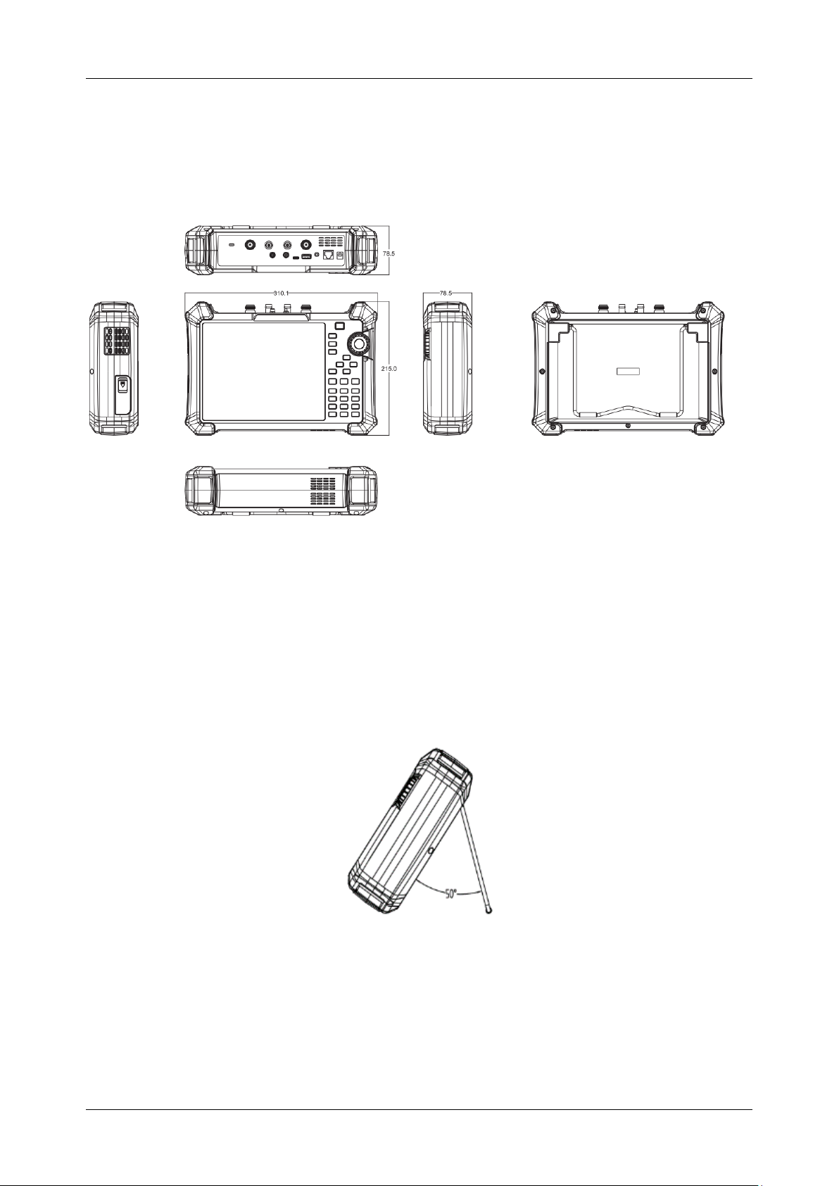
1.2.1 Appearance and Dimension
Figure 1-1 Front and lateral View
The included tilting stand is available for desktop operation. The tilting bracket provides a backward tilt
for improved stability. To deploy the tilt bracket, pull the bottom of the tilt bracket away from the back
of the instrument. To retract the tilting bracket, push the bottom of the bracket toward the back of the
instrument.
Figure 1-2 Side View
Unit:mm
Page 27
SHA850A User Manual
www.siglent.com 3
1.2.2 Power Supply Information
The battery that comes with the SHA800A may need to be recharged before use. The device can use
the supplied AC-DC adapter (refer to the product technical data sheet for ordering information). The
specifications of the input AC power supply are: 100-240V, 50/60Hz; Or charge through the on-board
DC adapter in the accessory.
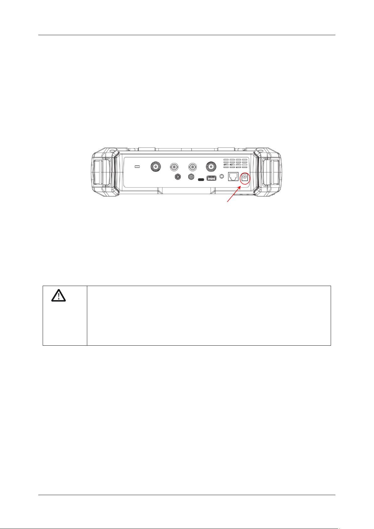
Specifically, the analyzer can be connected to the adapter according to the power socket shown in the
figure below.
Figure 1-3 Rear View and Power
◆ Adapter factory configuration is the 12V 4A
◆ Battery factory installed, the user can change itself
WARNING
This instrument can only use Siglent approved batteries, adapters and
chargers. When using an onboard DC adapter, always ensure that the power
supply is rated at least 75 W @ 15 VDC and that there is no dust or debris on
the socket. If the adapter plug becomes hot during operation, discontinue use
immediately. Siglent recommends taking out the batteries when devices aren't
used for too long.
Power socket
Page 28
SHA850A User Manual
4 www.siglent.com
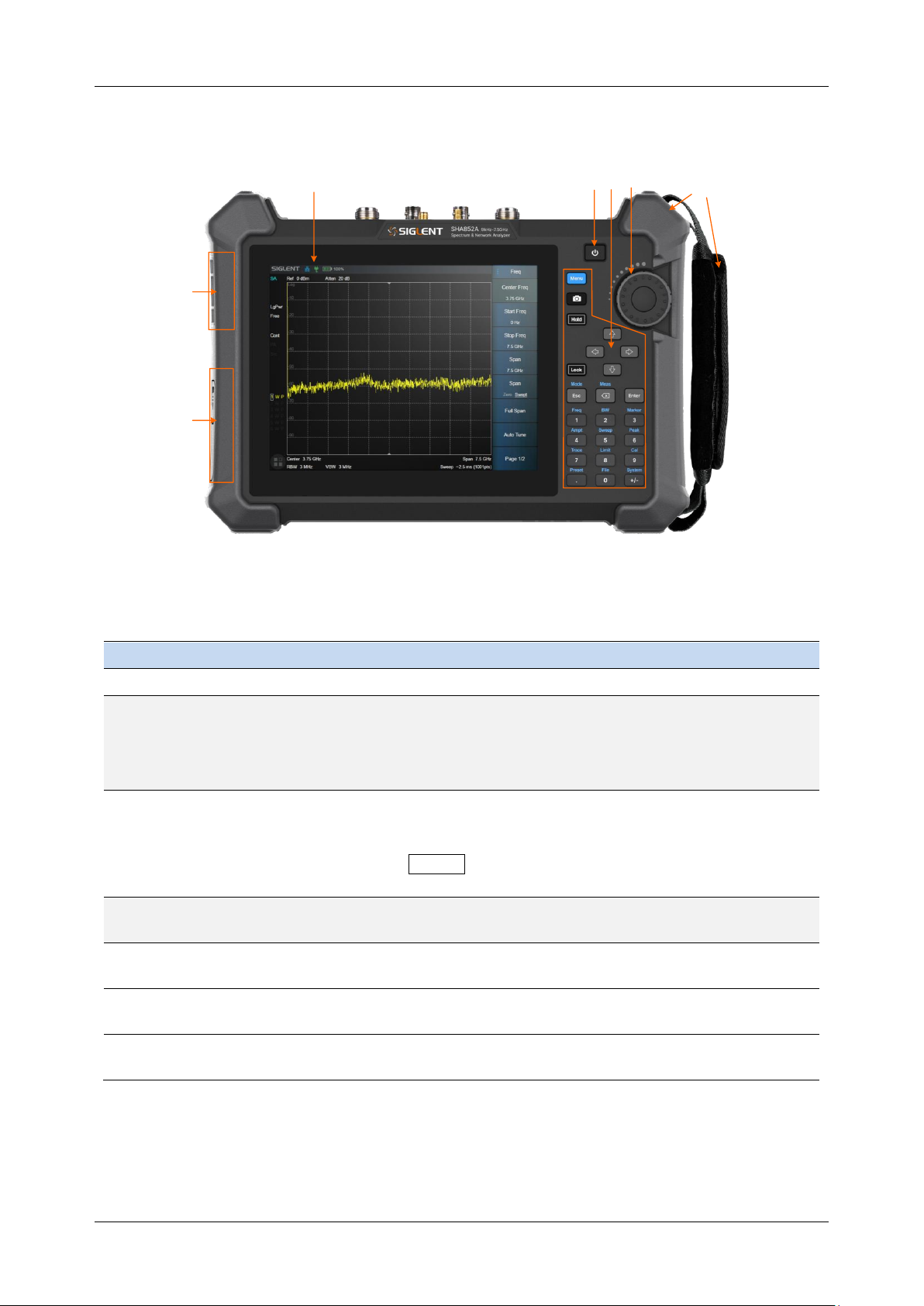
1.3 Front Panel
1
2 3 4
5
6
7
Figure 1-4 the Front Panel
Table 1-1 Front Panel Description
NO.
Name
Description
1
LCD Screen
8.4 inch multi-touch screen, resolution 800*600
2
Power Switch
Stand by status: Orange
Power on status: White
Short press: To Stand by status with current state saved
Long press: To Stand by status without current state saved
3
Function Keys
Complete the function control and parameter input of the
analyzer, and most operations can be completed by the touch
screen.
Press Lock to turn off/on the keyboard and touch
functions.
4
Three-dimensional
knob
Complete the quick adjustment and selection of parameters.
5
Fan vent
Built-in fan external exhaust port. Please ensure that this vent
is unblocked.
6
Battery case cover
Internal battery protection cover. Remove during battery
replacement.
7
Detachable
hand strap
Convenient hand force, can be installed on both sides.
Page 29
SHA850A User Manual
www.siglent.com 5
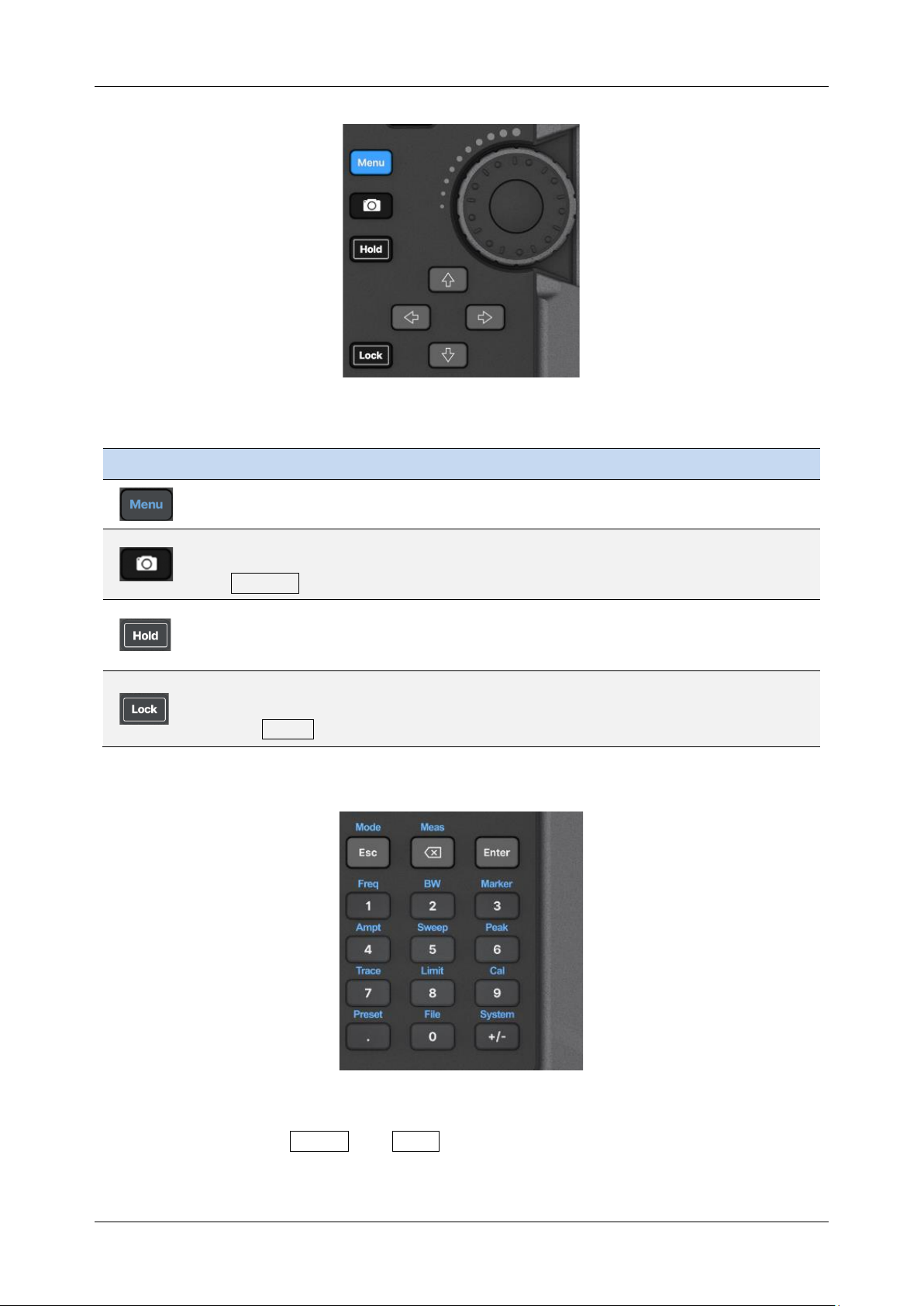
Table 1-2 Shorcut Keys Description
Name
Description
The menu selection window pops up on the screen, and you can use the touch
screen control to directly enter a function menu.
Shortcut screenshot button to save the current screen display as a picture. Save
parameters, such as path, reverse color, and screenshot area, to be set in
System > File.
Measurement control, pause or resume the current measurement process.
When the button light is on, the measurement is suspended. When the button
light is off, the measurement is resumed.
Key and touch screen lock control.
When the button light is on, all key pad buttons and touch screen buttons except
the Lock button are locked to prevent misoperation.
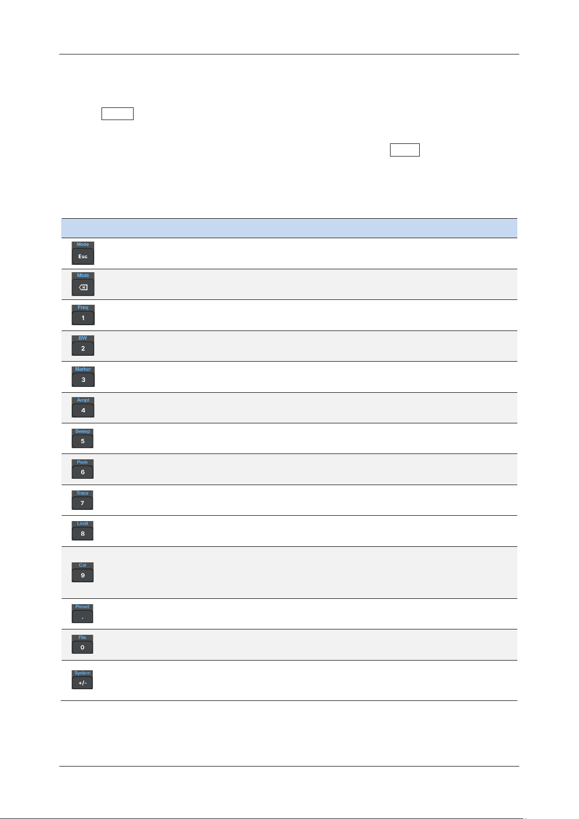
The function key part of the front panel is the reuse key of menu selection mode and value input mode,
which can be switched by Enter and Esc :
Page 30
SHA850A User Manual
6 www.siglent.com
◆ Under default reset, the operation interface is in menu selection mode, and function keys will
be identified as the blue silk screen function identifier on the upper side of the key. Use
Enter to switch from menu selection mode to value input mode.
◆ When the operation interface is in value input mode, the multiplex key will be identified as the
white silk screen digital identifier inside the key. You can use Esc to switch from value
input mode to menu selection mode.
Table 1-3 Function Keys Description
Name
Description
Menu selection mode, to select the analyzer operation mode, such as spectrum
analysis mode, antenna and cable test mode, network analyzer mode, etc.
In menu selection mode, control of mode measurement parameters, such as
average times, specific test items, etc.
In menu selection mode, frequency parameters are controlled. In time domain
analysis, length (distance) parameters are controlled.
Menu selection mode, bandwidth class parameter control, such as RBW, VBW,
IFBW and so on.
In menu selection mode, control cursor Marker parameters, such as cursor type,
cursor positioning, noise cursor, N dB bandwidth, etc.
Menu selection mode, for amplitude class parameters control, such as scale and
unit, as well as preattenuator, preamplifier, amplitude correction, etc.
In the menu selection mode, control the scanning parameters, such as scanning
time and type, scanning number, trigger, gating, etc.
In the menu selection mode, control the peak parameters, such as peak search,
peak rule setting, etc.
In menu selection mode, trace parameters are controlled, such as trace state,
detection, mathematical calculation, normalization, etc.
In menu selection mode, control the parameters of limit line, such as limit line
editing, margin, test state setting, etc.
In menu selection mode, port calibration of antenna and cable test mode and
network analysis mode is carried out, such as selecting the type of mechanical
calibration part, user-defined calibration part parameters, loading electronic
calibration part, etc.
In menu selection mode, reset parameters can be controlled, such as reset status
definition, power-on status definition, user status definition, etc.
In the menu selection mode, you can perform file operations, such as saving and
invoking files, and viewing file browsers.
In menu selection mode, the system general information view, version and
calibration operation, as well as input and output port Settings, screen display
Settings, etc.
Page 31
SHA850A User Manual
www.siglent.com 7
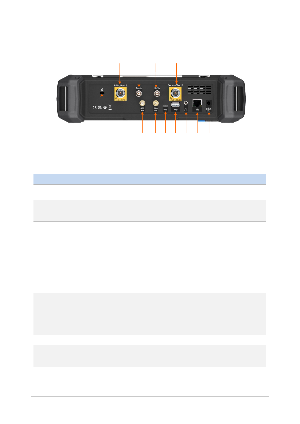
1.4 Rear Panel
1
2
4
5
6
8
9
10 11 12
3
7
Figure 1-5 Rear Panel
Table 1-4 Rear Panel Description
NO.
Name
Description
1
RF In/
Port 2
Signal input: 50Ω N female connector.
Maximum input ±50 VDC, + 30 dBm.
2
Trig In
Trigger input is a BNC female connector. When the analyzer uses an
external trigger mode, the connector receives a rising or falling edge of
an external trigger signal that is used to establish event synchronization.
3
Ref In
Reference clock input, BNC female connector. The analyzer can use an
internal reference clock or an external reference clock. If the instrument
detects a signal from an external 10 MHz reference clock, it
automatically uses the signal as the analyzer's reference clock source.
At this time the screen status bar frequency reference display external;
When the external 10 MHz reference signal is lost, exceeded, or not
connected, the analyzer's reference clock is automatically switched to
the internal 10 MHz reference clock, and the screen frequency
reference bar will display the internal.
[Ref In] is used to establish clock synchronization between multiple
instruments.
4
Source/
Port 1
The signal output and input terminals are 50Ω N female connectors.
In spectrum analysis mode, signal output as an independent signal
source.
In the network analysis mode, as the excitation and receiving interface,
this port built-in coupler, to achieve a single port vector network analysis
function.
5
K-groove
Slots are provided to accept Kensignton® cable locks.
6
GPS Ant
The GPS antenna port is a SMA female connector used to install the
GPS antenna and receive GPS satellite signals.
Can provide 3.3V DC feed for active GPS antenna.
Page 32
SHA850A User Manual
8 www.siglent.com
7
Bias Out
The offset voltage output port is a 50Ω female SMB connector.
Used to provide bias voltage for external signal amplifiers, such as
tower amplifiers.
8
USB
Device
The main USB port is TypeC. The analyzer can be used as a slave
device and connected to a PC via USB cable. The PC uses the
USB-TMC protocol to remotely control the analyzer.
9
USB
Host
USB slave port, TypeB. The analyzer can be used as the main device
and is connected to external USB devices through this port. For
example,
Connect external extended memory to read files in memory, or store the
current instrument state, data, or current screen display content into
memory;
Connect a USB keyboard, USB mouse, or other USB receiver; Connect
USB-GPIB adapter to realize GPIB remote control of analyzer;
Connect electronic calibration parts to realize automatic calibration of
analyzer.
10
Audio
output
3.5mm headphone jack. The analyzer provides AM and FM
demodulation functions.
The headphone jack is used to insert the headphone to listen to the
audio output of the demodulation signal. You can turn on or off the
headset and adjust the volume of the headset through the menu.
11
LAN
RJ45 ports. The analyzer is connected to the LAN through network
cable, and can be viewed and controlled remotely through VXI, Socket
protocol, or a web browser.
12
External
power
supply
2.5mm x 5.5mm barrel connector, connected to 12V 4A power adapter
charging port, center positive. Used to power devices and charge
batteries.
Page 33
SHA850A User Manual
www.siglent.com 9
WARNING
The analyzer does not support DC input. To avoid damage to the instrument,
the DC voltage component of the signal reaching the RF input must not exceed
50 V.
If possible, add an isolated DC component to the RF input of the analyzer
before signal measurement.
WARNING
In order to avoid damage to the instrument, the DC voltage component of the
signal input to the RF input should not exceed 50 V;
When the frequency is greater than 10 MHz, the maximum continuous power of
the RF signal shall not exceed +33 dBm.
When the frequency is less than 10 MHz, the maximum continuous power of
the RF signal should not exceed +20 dBm.
WARNING
Before connecting any signal, short connect the inner core of the test cable to
the housing floor to release the static electricity accumulated on the inner core
of the test cable.
Page 34
SHA850A User Manual
10 www.siglent.com
1.5 User Interface
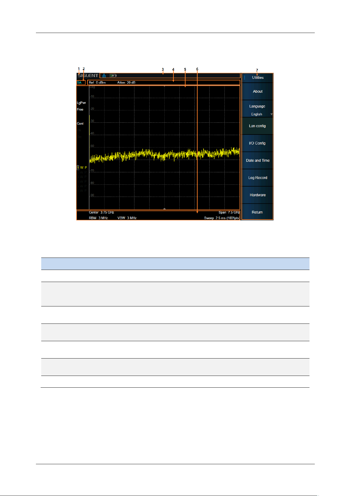
Figure 1-5 User Interface of spectrum analyzer mode
Table 1-5 Spectrum Analyzer Mode User Interface
No
Name
Description
1
SIGLENT
SIGLENT logo
2
Mode/Measure
Indicate the current working mode and measurement function of
the analyzer, and click to switch, such as spectrum analysis
mode, real-time spectrum mode, etc.
3
Hardware
status bar
Indicates the status of hardware, interfaces, etc.
4
Measurement
status bar
Indicates measurement status of reference level, attenuation,
cursor, etc.
5
Result display
area
The measurement results are displayed in various forms such as
spectral lines, cursors, tables and constellation charts.
6
Scan
parameter area
Indicates and controls major scan parameters.
7
Menu area
Used to configure measurement Settings.
Page 35
SHA850A User Manual
www.siglent.com 11
1.6 Touch screen and mouse operation
The analyzer provides a 8.4 inch multi-touch screen and supports various gesture operations
including:
◆ Slide the waveform left and right or up and down in the measurement result area to change the
X-axis center coordinate or Y-axis reference coordinatePerform two-points scaling in the
waveform area to change the X-axis span
◆ The waveform is scaled horizontally at two points in the measurement result area to change the
X-axis display range
◆ Click the shortcut menu area, working status area, scanning parameter area and menu area for
function selection
◆ Click editable parameters, virtual numeric keyboard or QWERT keyboard will pop up, parameter
or text editing
◆ Open and drag the cursor
◆ When the mouse is connected, clicking the left mouse button has the same effect as a single
touch
You can turn the touch screen function on and off via Lock .
Table 1-6 Touch Operations
No
Name
Description
1
Click
Most controls just need to be tapped, touched and released.
2
Double click
Some controls require double clicking.
If the second press is not detected within a specific time
period, the operation is cancelled or treated as a single press.
3
Press and drag
Some objects can be dragged.
This is done by gently holding down the action object and
dragging it to a new position while releasing it. For example,
you can drag items such as tags, limit line nodes, and center
frequencies by dragging tracks left or right.
4
Pinch or release
Some projects can be scaled down or expanded.
This is done by pressing down with two fingers at the same
time and gently holding the item as you pull the fingers closer
or further, then releasing. You can pull items in and out, such
as frequency spans, by touching and holding the trace in two
locations, then pulling your finger closer to narrow the span or
pulling your finger further to widen it.
Page 36
SHA850A User Manual
12 www.siglent.com
1.7 Firmware Operation
1.7.1 Check System Information
Users can get the system information by press System > “System” -> “About” , including
⚫ Product Model, Serial and Host ID
⚫ Software Version and hardware Version
⚫ Option Information
1.7.2 Load Option
Refer to the procedures below to activate the options you have purchased.
1 Press System > “System”-> “Load Option”
2 Enter the license key in the onscreen window. Press Enter to confirm your input and
terminate the license key input. Or
3 Load the .lic file provided by pressing File > “Load” from internal memory or USB stick.
The option will be enabled after rebooting.
1.7.3 Firmware Upgrade
Follow this procedure to update the instrument firmware:
1. Download the firmware package from an official SIGLENT website.
2. Extract and copy the .ADS file into the root directory of an USB stick.
3. Plug the USB stick into the USB Host connector. Press System > “System” -> “Update” ; find
the .ADS file in USB stick.
4. Press the “Load”, the analyzer will perform the update process automatically.
The upgrade process will take several minutes. When the upgrade is completed,
the machine will reboot.
Any interruption during the update process will result in update failure and system
data loss. This is not covered under the warranty and the user will bear repair
costs and shipping.
Do not remove the USB storage device until the update is finished.
1.8 Communication and Remote Control
The analyzer supports communication with computers via USB, LAN, and GPIB-USB interfaces. By
using these interfaces, in combination with programming languages and/or NI-VISA software, users
can remotely control the analyzer based on a SCPI (Standard Commands for Programmable
Instruments) compliant command set, LabView and IVI (Interchangeable Virtual Instrument), to
Page 37

SHA850A User Manual
www.siglent.com 13
interoperate with other programmable instruments.
You can also go to System > System > Interface Settings > Web Services and set the
corresponding communication port to view and control the analyzer directly on a PC or mobile
terminal using a web browser. For more details, refer to the ‘User Guide’.
1.9 Service and Support
SIGLENT warrants that the products that it manufactures and sells will be free from defects in
materials and workmanship for a period of three years (accessories for a period of one year) from the
date of shipment from an authorized Siglent distributor.
If the product proves defective within the respective period, SIGLENT will provide repair or
replacement as described in the complete warranty statement. To arrange for service or obtain a copy
of the complete warranty statement, please contact your nearest Siglent sales and service office.
Except as provided in this summary or the applicable warranty statement, SIGLENT makes no
warranty of any kind, express or implied, including without limitation the implied warranties of
merchantability and fitness for a particular purpose. In no event shall SIGLENT be liable for indirect,
special or consequential damages.
1.10 Troubleshooting
Troubleshoot the analyzer according to the following steps:
1. Switch on the power and the instrument will enter the charging state. The backlight of the power
switch on the front panel will light up orange (charging)/green (full).
If the power switch on the front panel is not on:
◆ Check that the power switch is turned on and that the power connector is properly connected
2. Press the power switch on the front panel, and the instrument will turn on. The color of the power
switch on the front panel will turn white. At the same time, the fan on the back will turn and the
screen will light up.
If the instrument does not enter the power on state normally:
◆ Check whether the fan and screen are loose or damaged
◆ If the fan and screen are normally powered on, but the screen stops in the startup screen, or
the button does not respond
If the above problems exist, do not disassemble the instrument and contact SIGLENT in time.
3. The analyzer enters the working state normally, and the buttons and touch screen should
respond to the measurement operation normally.
If the instrument does not work properly:
Page 38

SHA850A User Manual
14 www.siglent.com
◆ Check that the analyzer is working in the remote control lock state
◆ Check whether the analyzer can be controlled using the mouse and keyboard
◆ Check whether the analyzer can be controlled using VNC or remote commands
◆ Press System > Self-Test > Screen Test/Key Test /LED test/Touch test to check
whether there is any response or interference between the key and screen
◆ Check whether strong electromagnetic fields exist around the analyzer. Strong
electromagnetic fields will affect the response of the capacitor touch screen
If the above problems exist, do not disassemble the instrument and contact SIGLENT in time.
4. The analyzer should be in scanning or measuring state when working normally, and the screen
waveform and parameters are in updating state.
If the instrument screen waveform or parameters are not updated for a long time:
◆ Check whether the current trace is in View state or multiple averaging state
◆ Check whether the trigger conditions are not met and wait. Check the trigger Settings and
whether there is a trigger signal
◆ Check whether it is currently in a single scan state, or whether it is in a measurement
calculation state
◆ Check whether the current scan time is set too long or whether the measured dwell time is
set too long
5. Incorrect or inaccurate measurement:
Users can obtain detailed instructions on technical indicators from the back of this manual to
calculate systematic errors, check measurement results and accuracy problems. To achieve the
performance indicators listed in this manual, you need:
◆ The instrument is in the calibration cycle, stored in the working temperature of 20℃~30℃ for
at least two hours, and preheated for more than 40 minutes
◆ Have a certain understanding of the measured signal, and set the appropriate parameters for
the instrument
◆ Check that external devices are properly connected and working, and that line losses are
correctly compensated
◆ Check whether signal tracing, frequency offset, amplitude offset, or correction functions are
applied
◆ Check whether an external reference clock source is applied
◆ The instrument is measured and calibrated regularly to compensate for measuring errors
caused by aging and other factors. For calibration, contact SIGLENT, Inc., or an authorized
measurement provider for paid service.
Page 39

SHA850A User Manual
www.siglent.com 15
6. Pop-up message:
The instrument will give prompt message, error message or status message according to the
state it is in. These messages can help the user to use the device correctly, not the device failure.
Page 40
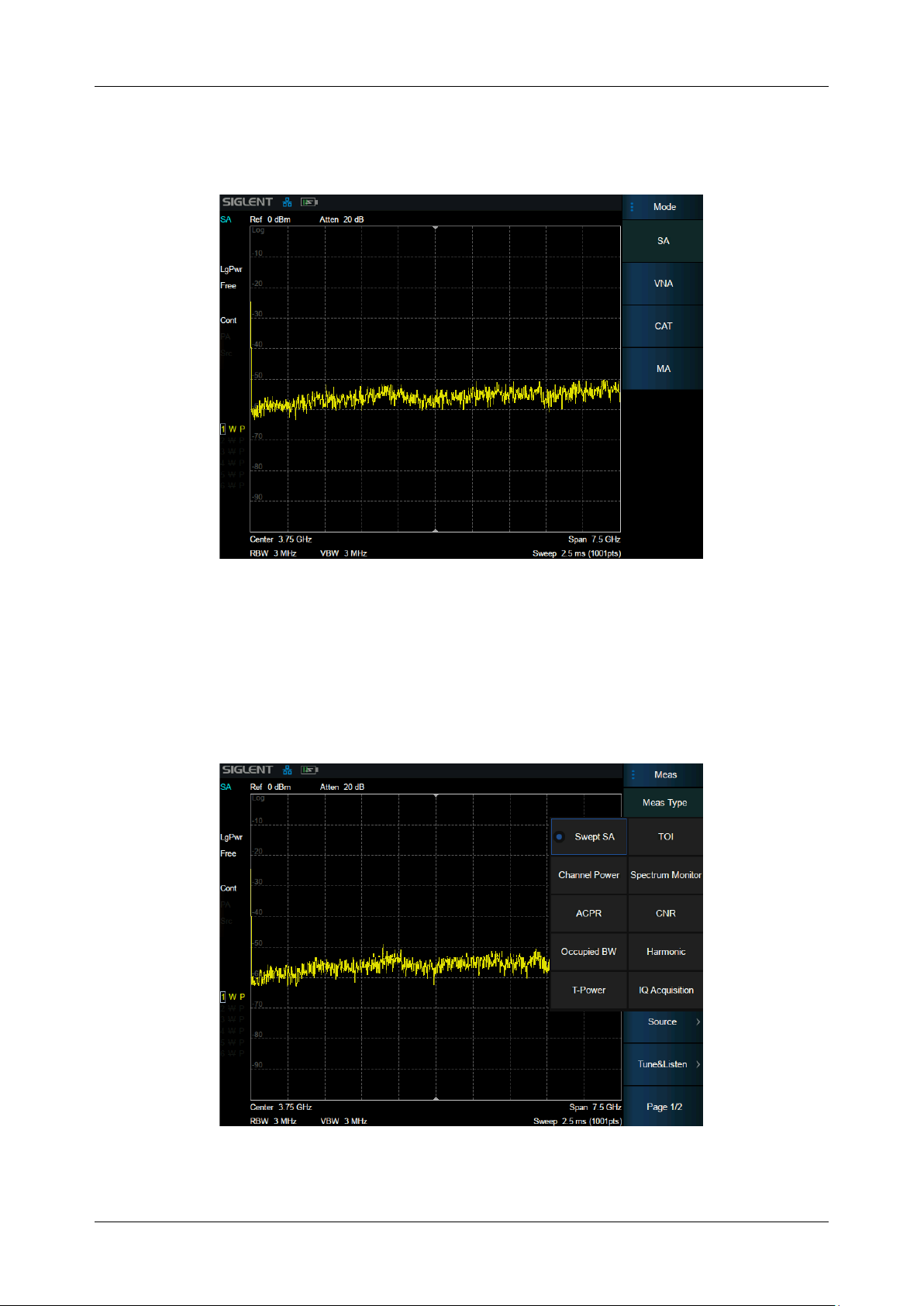
SHA850A User Manual
16 www.siglent.com
2 Mode & Measurement
The analyzer operates in multiple operating modes, each of which contains several measurements:
Figure 2-1 Mode selection
⚫ Spectrum Analyzer Mode (GPSA)
⚫ Cable and Antenna Mode (CAT)
⚫ Vector Network Analyzer Mode (VNA)
⚫ Modulation Analyzer Mode (MA)
Figure 2-2 GPSA measurement selection
Page 41
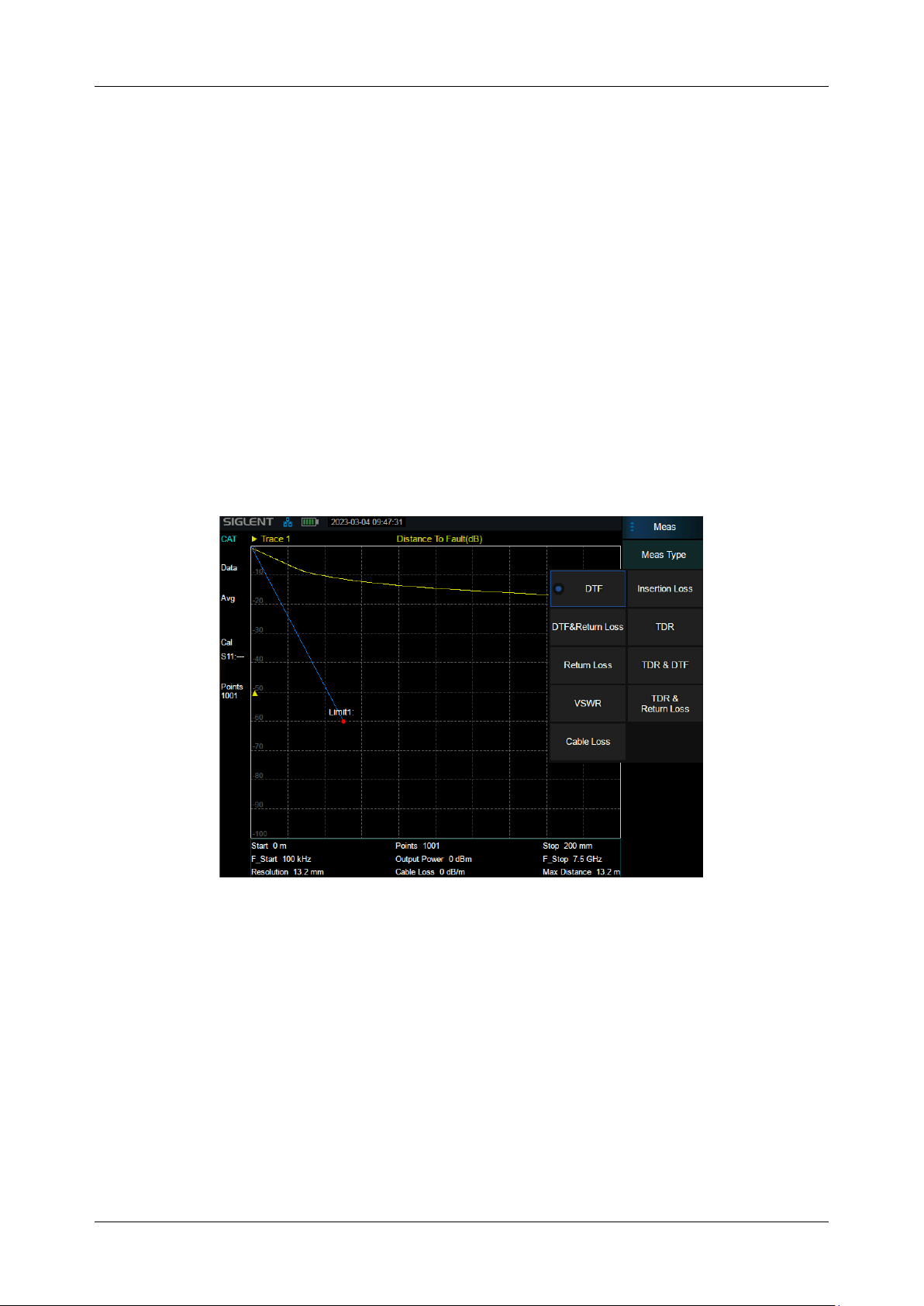
SHA850A User Manual
www.siglent.com 17
⚫ Spectrum Analyzer Mode(GPSA) :
Swept Spectrum Analyzer (Swept SA)
Channel Power (CH Power)
Adjacent Channel Power Ratio (ACPR)
Occupied BW (OBW)
T-Power (T-Power)
Third Order Intercept (TOI)
Spectrum Monitor (Spectrum Monitor)
Carrier Noise Ratio (CNR)
Harmonic Analysis (Harmonic)
IQ Acquisition
Figure 2-3 CAT measurement selection
⚫ Cable and Antenna Mode (CAT) :
Distance to Fault
Return Loss
VSWR
Cable Loss
Insertion Loss
Time Domain Reflectometry
DTF&Return Loss
Page 42

SHA850A User Manual
18 www.siglent.com
TDR&Return Loss
TDR&DTF
⚫ Vector Network Analyzer Mode (VNA)
⚫ Modulation Analyzer Mode (MA) :
Digital Modulation Analyzer (DMA)
Analog Modulation Analyzer (AMA)
The analyzer supports the creation of multiple independent modes / measurements, but only one of
them can be activated at the same time. Wait until the next activation to restore the state before
switching
Command Format
:INSTrument[:SELect]
:INSTrument[:SELect]?
Instruction
Select the working mode of the spectrum analyzer.
Parameter Type
Enumeration
Parameter Range
SA: Spectrum Analysis Mode
MA: Modulation Analysis
RTSA: Real-Time Spectrum Analysis
Return
Enumeration
Example
:INSTrument MA
Command Format
:INSTrument:MEASure
:INSTrument:MEASure?
Instruction
Get/Set the measurement mode.
Parameter Type
Enumeration
Parameter Range
SA: Spectrum Analysis
ACPR: Adjacent Channel Power Ratio
CHPower: Channel Power
OBW: Occupy Bandwidth
TPOWer: Time-Domain Power
SPECtrogram: Spectrogram
TOI: Third-Order Intermodulation
HARMonics: Harmonic Analysis
CNR: Carrier-to-Noise Ratio
Return
Enumeration: SA||ACPR|CHP|OBW|TPOW|SPEC|TOI|HARM|CNR
Example
:INSTrument:MEASure ACPR
Page 43

SHA850A User Manual
www.siglent.com 19
3 Spectrum Analyzer Mode
The Spectrum Analyzer Mode is the default mode of the analyzer.
3.1 Frequency & Span
3.1.1 Frequency & Span
Set the frequency-related parameters and functions of the analyzer. The sweep will restart every time
the frequency parameters are modified.
The frequency range of a channel can be expressed by these parameters: Start Frequency, Center
Frequency, Stop Frequency and Span. If any of the parameters change, the others will be adjusted
automatically in order to ensure the coupling relationship among them:
center
start
stop
/2
span
stop
start
, Where
is the span.
The LO will sweep from the Start Frequency to the Stop Frequency if the Span > 0, while the LO is
fixed at a constant frequency if Span = 0 ( Zero Span).
Span change, associated with BW and scan parameters.
After the frequency related parameters are changed, restart scanning \ measurement.
Last sweep sets the sweep width to the value before the last modification.
Zoom in sets the sweep width to half the current sweep width value.
Zoom out sets the sweep width to twice the current sweep width value.
Command Format
[:SENSe]:FREQuency:CENTer
[:SENSe]:FREQuency:CENTer?
Instruction
Sets the center frequency of the spectrum analyzer.
Gets the center frequency.
Parameter Type
Float, unit: Hz, kHz, MHz, GHz
Parameter Range
50 Hz~7.5 GHz
Zero Span: 0 ~ 7.5 GHz
Return
Float, unit: Hz
Example
:FREQuency:CENTer 0.2 GHz
Command Format
[:SENSe]:FREQuency:STARt
[:SENSe]:FREQuency:STARt?
Instruction
Sets the start frequency of the spectrum analyzer.
Gets the start Frequency.
Parameter Range
0 Hz ~ 7.5 GHz
Zero Span: 0 ~ 7.5 GHz
Example
:FREQuency:STARt 100 Hz
Page 44

SHA850A User Manual
20 www.siglent.com
Command Format
[:SENSe]:FREQuency:STOP
[:SENSe]:FREQuency:STOP?
Instruction
Sets the stop frequency of the spectrum analyzer.
Gets the stop frequency.
Parameter Type
Float, unit: Hz, kHz, MHz, GHz
Parameter
Range
100 Hz ~ 7.5 GHz
Zero Span: 0 ~ 7.5 GHz
Return
Float, unit: Hz
Example
:FREQuency:STOP 1.0 GHz
Command Format
[:SENSe]:FREQuency:SPAN
[:SENSe]:FREQuency:SPAN?
Instruction
Sets the frequency span. Setting the span to 0 Hz puts the analyzer into zero
span.
Gets span value.
NOTE
Channel Power Only : [:SENSe]:CHPower:REQuency:SPAN
OBW Only : [:SENSe]:OBWidth:REQuency:SPAN
ACPR Only : [:SENSe]:ACPower:REQuency:SPAN
TOI Only : [:SENSe]:TOI:REQuency:SPAN
CNR Only : [:SENSe]:CNR:REQuency:SPAN
Parameter Type
Float, unit: Hz, kHz, MHz, GHz
Parameter Range
0 Hz, 100 Hz ~ 28GHz
Return
Float, unit: Hz
Example
:FREQuency:SPAN 1 GHz
Command Format
[:SENSe]:FREQuency:SPAN:FULL
Instruction
Sets the frequency span to full scale.
Example
:FREQuency:SPAN:FULL
Command Format
[:SENSe]:FREQuency:SPAN:ZERO
Instruction
Sets the frequency span to zero span.
Example
:FREQuency:SPAN:ZERO
Command Format
[:SENSe]:FREQuency:SPAN:PREVious
Instruction
Sets the frequency span to the previous span setting.
Example
:FREQuency:SPAN:PREVious
Command Format
[:SENSe]:FREQuency:SPAN:HALF
Instruction
Sets the frequency span to half of the current span setting.
Example
:FREQuency:SPAN:HALF
Command Format
[:SENSe]:FREQuency:SPAN:DOUBle
Instruction
Sets the frequency span to double the current span setting.
Example
:FREQuency:SPAN:DOUBle
Page 45

SHA850A User Manual
www.siglent.com 21
3.1.2 X Axis Scale
Set the scale type of X-axis to Linear (Lin) or Logarithmic (Log) scale.
In Log scale type, the frequency scale of X-axis is displayed in the logarithmic form.
Command Format
:DISPlay:WINDow:TRACe:X[:SCALe]:SPACing
:DISPlay:WINDow:TRACe:X[:SCALe]:SPACing?
Instruction
Sets the The x type
Gets the The x type
Parameter Type
enumeration
Return
LOG/LIN
Example
:DISPlay:WINDow:TRACe:X:SPACing LOG
:DISPlay:WINDow:TRACe:X:SPACing?
3.1.3 Freq Offset
Set the frequency offset value to illustrate the frequency conversion between the measured device
and the input of the spectrum analyzer.
⚫ This parameter does not affect any hardware settings of the spectrum analyzer, but only changes
the display values of center frequency, start frequency and stop frequency.
⚫ To eliminate the frequency offset value, the frequency offset value can be set to 0 Hz.
Command Format
[:SENSe]:FREQuency:OFFSet
[:SENSe]:FREQuency:OFFSet?
Instruction
Sets the frequency offset of the spectrum analyzer.
Gets the frequency offset.
Parameter Type
Float, unit: Hz, kHz, MHz, GHz
Parameter Range
-100 GHz ~ 100 GHz
Return
Float, unit: Hz
Example
:FREQuency:OFFSet 1 GHz
3.1.4 Freq Step
Setting the value of Freq Step will change the direction key step of center frequency, start frequency,
stop frequency and frequency offset.
⚫ At a fixed step change the value of the center frequency can reach the purpose of switching
measurement channels rapidly and continuously.
⚫ There are two kinds of frequency step modes:Auto and Manual. In Auto mode, the Freq step is
1/10 of the span in Non-zero span or equals the RBW while in Zero Span. In Manual mode, you
can set the step using the numeric keys.
Page 46

SHA850A User Manual
22 www.siglent.com
Command Format
[:SENSe]:FREQuency:CENTer:STEP[:INCRement]
[:SENSe]:FREQuency:CENTer:STEP[:INCRement]?
Instruction
Specifies the center frequency step size.
Gets the center frequency step.
Parameter Type
Float, unit: Hz, kHz, MHz, GHz
Parameter Range
1 Hz ~ 7.5 GHz
Return
Float, unit: Hz
Example
:FREQuency:CENTer:STEP 2 MHz
Command Format
[:SENSe]:FREQuency:CENTer:STEP:AUTO OFF|ON|0|1
[:SENSe]:FREQuency:CENTer:STEP:AUTO?
Instruction
Specifies whether the step size is set automatically based on the span.
Gets center frequency step mode.
Parameter Type
Boolean
Parameter Range
OFF|ON|0|1
Return
0|1
Example
:FREQuency:CENTer:STEP:AUTO OFF
3.1.5 Auto Tune
Automatically search the signal in the full frequency band and adjust the frequency and amplitude
parameters to the best state. One key to perform signal search and automatic parameter setting.
⚫ When this function is enabled, Auto Tune is displayed in the status bar of the screen. After the
automatic search is complete, Auto Tune disappears.
⚫ Reference level, scale size, input attenuation and other parameters may be modified during
automatic search.
Command Format
[:SENSe]:FREQuency:TUNE:IMMediate
Instruction
Perform auto tune
Parameter Type
No parameter
Parameter Range
No parameter
Return
No return
Example
:FREQuency:TUNE:IMMediate
3.2 BW
The bandwidth menu contains the RBW (Resolution Bandwidth), VBW (Video Bandwidth), average
type and filter type. Filter type includes the EMI filter type that enables EMI measurement controls.
3.2.1 Resolution Bandwidth
Set the resolution bandwidth in order to distinguish between signals which have frequency
components that are near one another.
⚫ Reducing the RBW will increase the frequency resolution, but will also increase the sweep time
dramatically (Sweep Time is affected by a combination of RBW and VBW when the analyzer is in
Page 47

SHA850A User Manual
www.siglent.com 23
Auto mode).
⚫ Generally, the frequency resolution ability is affected by RBW, RBW Filter shape factor, LO
Phase noise, and LO Residual FM.
⚫ RBW varies with the span (non-zero span) in Auto RBW mode.
⚫ Under EMI filter, RBW can only be set to 200 Hz, 9 kHz, 120 kHz and 1 MHz with a 6dB shape
factor.
Command Format
[:SENSe]:BWIDth[:RESolution]
[:SENSe]:BWIDth[:RESolution]?
Instruction
Specifies the resolution bandwidth. For numeric entries, all RBW types choose
the nearest (arithmetically, on a linear scale, rounding up) available RBW to the
value entered.
Gets the resolution bandwidth.
NOTE
[:SENSe]:CHPower:BANDwidth[:RESolution]
[:SENSe]:OBWidth:BANDwidth[:RESolution]
[:SENSe]:ACPower:BANDwidth[:RESolution]
[:SENSe]:TOI:BANDwidth[:RESolution]
[:SENSe]:HARMonics:BANDwidth[:RESolution]
[:SENSe]:TPOWer:BANDwidth[:RESolution]
[:SENSe]:SPECtrogram:BANDwidth[:RESolution]
[:SENSe]:CNR:BANDwidth[:RESolution]
Parameter Type
Discrete
Parameter Range
1Hz , 3Hz , 10 Hz , 30 Hz , 100 Hz , 300 Hz , 1 kHz , 3 kHz , 10 kHz , 30 kHz ,
100 kHz , 300 kHz , 1 MHz , 3 MHz , 10 MHz
Return
Float, unit: Hz
Example
:BWIDth 1 kHz
Command Format
[:SENSe]:BWIDth[:RESolution]:AUTO OFF|ON|0|1
[:SENSe]:BWIDth[:RESolution]:AUTO?
Instruction
Turn on/off auto resolution bandwidth state.
Gets the resolution bandwidth auto state.
Parameter Type
Boolean
Parameter Range
OFF|ON|0|1
Return
0|1
Example
:BWID:AUTO On
3.2.2 Video Bandwidth
Set the video bandwidth in order to filter out the noise outside the video band.
⚫ Reducing the VBW will smooth the trace and helps to highlight small signals from noise, but it will
also increase the sweep time (Sweep Time is affected by a combination of RBW and VBW when
it is in Auto mode).
⚫ VBW varies with RBW when it is in Auto mode. While in Manual mode, VBW is not affected by
RBW.
Page 48

SHA850A User Manual
24 www.siglent.com
Command Format
[:SENSe]:BWIDth:VIDeo
[:SENSe]:BWIDth:VIDeo?
Instruction
NOTE
Specifies the video bandwidth.
Gets the video bandwidth.
[:SENSe]:OBWidth:BANDwidth[:RESolution]
[:SENSe]:ACPower:BANDwidth[:RESolution]
[:SENSe]:TOI:BANDwidth[:RESolution]
[:SENSe]:HARMonics:BANDwidth[:RESolution]
[:SENSe]:TPOWer:BANDwidth[:RESolution]
[:SENSe]:SPECtrogram:BANDwidth[:RESolution]
[:SENSe]:CNR:BANDwidth[:RESolution]
Parameter Type
Discrete
Parameter Range
1Hz , 3Hz , 10 Hz , 30 Hz , 100 Hz , 300 Hz , 1 kHz , 3 kHz , 10 kHz , 30 kHz ,
100 kHz , 300 kHz , 1 MHz , 3 MHz , 10 MHz
Return
Float, unit: Hz
Example
:BWIDth:VIDeo 10 kHz
Command Format
[:SENSe]:BWIDth:VIDeo:AUTO OFF|ON|0|1
[:SENSe]:BWIDth:VIDeo:AUTO?
Instruction
This command turns on/off auto video bandwidth state.
Gets the video bandwidth state.
Parameter Type
Boolean
Parameter Range
OFF|ON|0|1
Return
0|1
Example
BWIDth:VIDeo:AUTO OFF
3.2.3 V/R Ratio
Set the ratio of VBW to RBW. This value is different while measuring different kinds of signals:
⚫ Sine/Continuous Wave (CW) signals:Use 1 to 3 (for faster sweeps)
⚫ Pulsed/transient signals:Use 10 (to reduce the influence on the amplitude of transient signals)
⚫ Noise signals:Generally use 0.1 (to obtain the average of noises)
Command Format
[:SENSe]:BWIDth:VIDeo:RATio
[:SENSe]:BWIDth:VIDeo:RATio?
Instruction
Specifies the ratio of the video bandwidth to the resolution bandwidth.
Gets the ratio of the video bandwidth to the resolution bandwidth.
Parameter Type
Discrete, Float
Parameter Range
0.001, 0.003, 0.01, 0.03, 0.1, 0.3, 1.0, 3.0, 10.0, 30.0, 100.0, 300.0, 1000.0
Return
Float
Example
:BWIDth:VIDeo:RATio 30
Page 49

SHA850A User Manual
www.siglent.com 25
3.3 Sweep
3.3.1 Sweep Points
The number of sweep points represents the number of sweep and trace displayed points
(201~10001).
More sweep points will improve the resolution of waveform, but also affect the minimum sweep time,
and increase the time of data processing and remote access to data, and reduce the response rate.
Under the influence of the scheme, when the sweep type is FFT, the sweep points cannot remain
effective all the time, and the actual output points may be less than the sweep points in some states.
Command Format
[:SENSe]:SWEep:POINts
[:SENSe]:SWEep:POINts?
Instruction
Sets sweep points.
Gets sweep points.
Parameter Type
integer
Parameter Range
201-10001
Example
:SWEep:POINts 2001
:SWEep:POINts?
3.3.2 Sweep Time & Sweep Time Rules
When the sweep type is normal swept, you can change the sweep time (SWT) to control the time
required to sweep the current frequency range. The sweep time supports automatic mode and manual
mode:
AutoSWT refers to the appropriate sweep time of the analyzer according to the relevant configuration
line operation, which satisfies the following calculation logic:
When Span>0:
、
When Span=0:
Where velocity factor K =3 or 12, corresponding to two supported Sweep Time Rules:Speed or
Accuracy; Represents the DSP response time of a sweep point,it is inversely
correlated with RBW value.
Page 50

SHA850A User Manual
26 www.siglent.com
Users can also manually set the sweep time based on actual requirements.But it needs to be satisfied:
When Span>0: 1ms SWT 4ks
When Span=0: 1us SWT 6ks
In general, the manual sweep time should not be longer than the automatic sweep time in this
condition. Otherwise, unforeseeable anomalies may be caused and may be marked (UNCAL).
It should be pointed out in particular that under the influence of the scheme, when the sweep type is
FFT, the sweep time can only be calculated by the instrument itself, and any modification related to
the sweep time cannot take effect.
Command Format
[:SENSe]:SWEep:TIME
[:SENSe]:SWEep:TIME?
Instruction
Specifies the time in which the instrument sweeps the display. A span value of
0 Hz causes the analyzer to enter zero span mode. In zero span the X-axis
represents time rather than frequency.
Parameter Type
Float, unit: ks, s, ms, us
Parameter Range
1us ~ 6000s
Return
Float, unit: s
Example
:SWEep:TIME 5s
Command Format
[:SENSe]:SWEep:TIME:AUTO OFF|ON|0|1
[:SENSe]:SWEep:TIME:AUTO?
Instruction
This command turns on/off auto sweep time state.
Parameter Type
Boolean
Parameter Range
OFF|ON|0|1
Return
0|1
Example
:SWEep:TIME:AUTO ON
Command Format
[:SENSe]:SWEep:SPEed NORMal|ACCUracy
[:SENSe]:SWEep:SPEed?
Instruction
Toggles the sweep speed between normal and accuracy.
Parameter Type
Enumeration
Parameter Range
ACCUracy|NORMal
Example
:SWEep: SPEed NORMal
3.3.3 Sweep Time Estimate
The estimated sweep time represents the time actually consumed by each sweep, including data
sampling time (sweep time) and related scheduling time.
Page 51
SHA850A User Manual
www.siglent.com 27
The estimated sweep time cannot be modified。
3.3.4 Sweep/Measure
Sweep/Measure
Single/Continue controls analyzer to perform single or continuous sweep/measure,
Restart
Restart the current sweep or measure. In particular, if the sweep parameters are modified, a restart
will be performed.
Command format
:INITiate:CONTinuous OFF|ON|0|1
:INITiate:CONTinuous?
Instructions
Sets continuous sweep mode on-off.
Gets continuous sweep mode state.
Parameter Type
Boolean
Parameter Range
OFF|ON|0|1
Return
0|1
Example
:INITiate:CONTinuous OFF
Command Format
:INITiate[:IMMediate]
Instruction
Restarts the current sweep.
Example
:INITiate:IMMediate
Command Format
:INITiate:RESTart
Instruction
Restarts the current sweep.
Example
:INITiate:RESTart
3.4 Amplitude
Set the amplitude parameters of the analyzer. Through modifying these parameters, signals under
measurement can be displayed in a proper mode for easier observation and minimum error. Any
change of Ref Level, Attenuator Value, Preamp mode and Ref Offset will restart sweep.
3.4.1 Ref Level
Set the maximum power or voltage that can be currently displayed in the trace window. The value is
displayed at the upper left corner of the screen grid.
The maximum reference (Ref) level available is affected by the maximum mixing level; input
attenuation is adjusted under a constant maximum mixing level in order to fulfill the following
condition:
Page 52
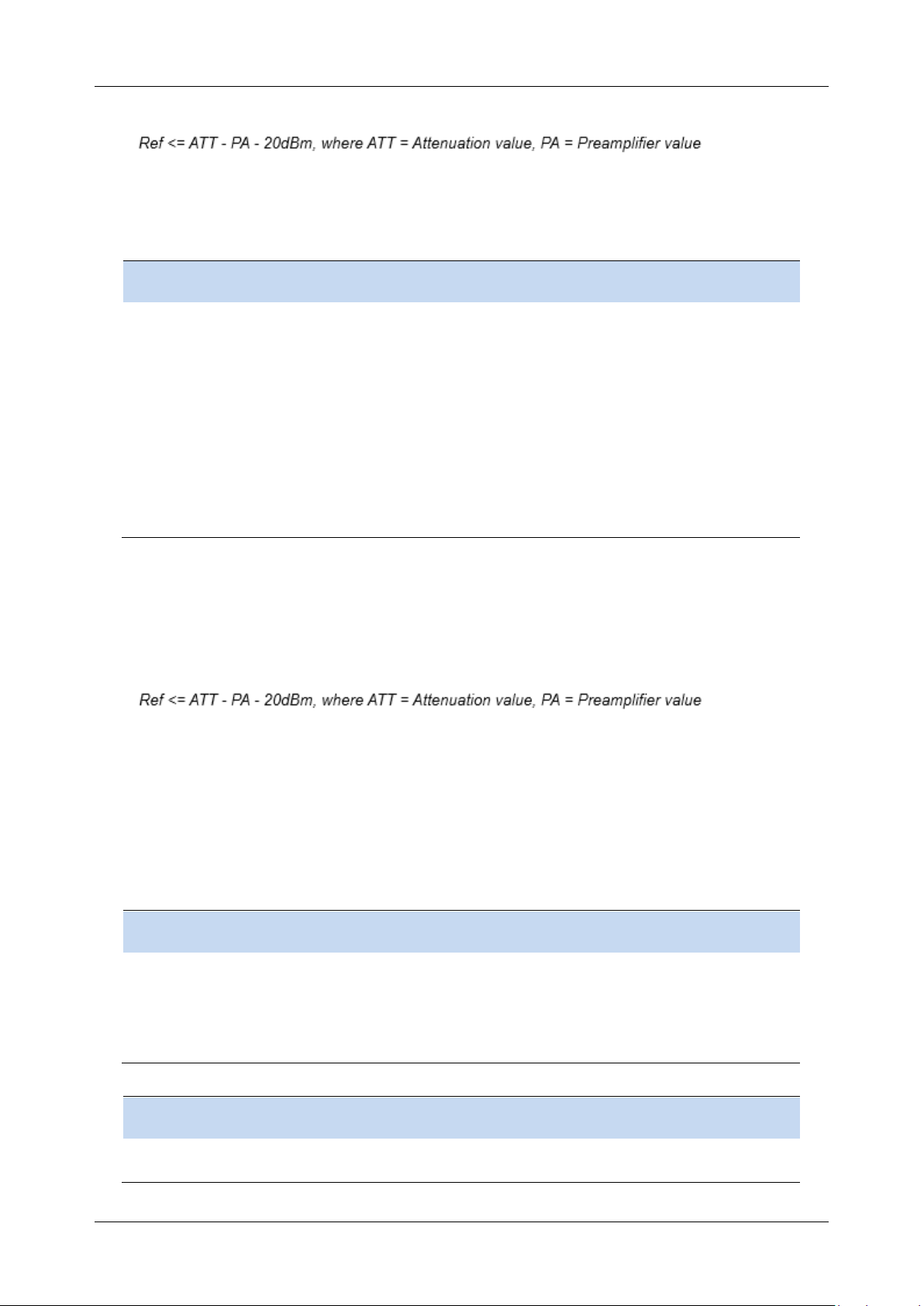
SHA850A User Manual
28 www.siglent.com
Note: the maximum reference level of different machine models may be different, please refer to the
data manual specifically.
Command Format
:DISPlay:WINDow:TRACe:Y[:SCALe]:RLEVel
:DISPlay:WINDow:TRACe:Y[:SCALe]:RLEVel?
Instruction
This command sets the reference level for the Y-axis.
Gets reference level.
Parameter Type
Float, unit: dBm, dBmV, dBuV, dBuA, V, W
Parameter Range
Unit is dBm : -170 dBm ~ 23 dBm
Unit is dBmV : -123.01 dBmV ~ 69.99 dBmV
Unit is dBuV : -63.01 dBuV ~ 129.99 dBuV
Unit is dBuA : -96.99 dBuA ~ 96.01 dBuA
Unit is Volts : 707.11pV ~ 3.16 V
Unit is Watts : 0W ~ 199.53m W
Return
Float , unit: dBm
Example
:DISPlay:WINDow:TRACe:Y:RLEVel 20 DBM
3.4.2 Attenuator
Set the value for the internal attenuator of the RF input. So that the large signal can be low distortion
and the small signal can pass through the mixer with low noise.
Input attenuation can be set up to auto or manual mode.
⚫ Auto mode: the attenuation value is automatically adjusted according to the state of preamplifier
and the current reference level.
⚫ The maximum input attenuation can be set to 50dB , resolution: 2dB. When the set parameters
do not meet the above formula, you can adjust the reference level.
Command format
[:SENSe]:POWer[:RF]:ATTenuation
[:SENSe]:POWer[:RF]:ATTenuation?
Instructions
Sets/gets the attenuation value
Parameter Type
Integer
Parameter Range
0 dB ~ 50 dB (Even gears only)
Return
Integer , unit dB
Example
:POWer:ATTenuation 10
Command format
[:SENSe]:POWer[:RF]:ATTenuation:AUTO OFF|ON|0|1
[:SENSe]:POWer[:RF]:ATTenuation:AUTO?
Instructions
Sets/gets the auto attenuation value switch
Parameter Type
Boolean
Page 53

SHA850A User Manual
www.siglent.com 29
Parameter Range
OFF|ON|0|1
Return
0|1
Example
:POWer[:RF]:ATTenuation:AUTO ON
3.4.3 RF Preamp
Control the state of the internal preamplifier (PA) located in the RF input signal path. When the
signal-under-measurement is small, turning on the preamplifier can reduce the displayed noise level
and aid distinguishing small signals from the noise.
The corresponding icon “PA” will appear at the left side of the screen when the preamplifier is turned
on.
Command format
[:SENSe]:POWer[:RF]:GAIN[:STATe] OFF|ON|0|1
[:SENSe]:POWer[:RF]:GAIN[:STATe]?
Instructions
Sets/gets the preset amplifier inside the switch spectrometer
Parameter Type
Boolean
Parameter Range
OFF|ON|0|1
Return
0|1
Example
:POWer:GAIN ON
3.4.4 Ref Offset
Assign an offset to the reference level to compensate for gains or losses generated between the
device under measurement and the analyzer.
The change of this value changes both the reference level readout and the amplitude readout of the
marker; but does not impact the position of traces on the screen.
Command format
:DISPlay:WINDow:TRACe:Y:SCALe:RLEVel:OFFSet
:DISPlay:WINDow:TRACe:Y:SCALe:RLEVel:OFFSet?
Instructions
Sets/gets the frequency offset
Parameter Type
Float
Parameter Range
-100 dB~100 dB
Return
Float , unitdB
Example
:DISPlay:WINDow:TRACe:Y:SCALe:RLEVel:OFFSet 2
3.4.5 Y Axis Scale
3.4.5.1 Scale
Users can change the display range of Y axis by adjusting the scale. The scaling is allowed only the
scale type is Log.
⚫ Setting different scales can adjust the display range of the current interface amplitude;
Page 54

SHA850A User Manual
30 www.siglent.com
Command format
:DISPlay:WINDow:TRACe:Y[:SCALe]:PDIVision
:DISPlay:WINDow:TRACe:Y[:SCALe]:PDIVision?
Instructions
Sets/gets the scale on which trace logarithms are displayed
Parameter Type
Float
Parameter Range
0.1 dB ~ 20 dB
Return
Float , unit dB
Example
:DISPlay:WINDow:TRACe:Y:PDIVision 10 dB
3.4.5.2 Scale Type
Set the scale type of the Y-axis to Lin or Log. The default is Log.
⚫ In Lin mode, the vertical Scale value cannot be changed. The Display area is set for reference
level of 0%.
⚫ In Log scale type, the Y-axis denotes the logarithmic coordinate. The value shown at the top of
the grid is the reference level and each grid represent the scale value. The unit of Y-axis will
automatically switch to the default unit (dBm) in Log scale type when the scale type is changed
from Lin to Log.
⚫ In Lin scale type, the Y-axis denotes the liner coordinate; the values shown at the top of the grid
and the bottom of the grid are the reference level and 0 V. The scale setting function is invalid.
The unit of Y-axis will automatically switch to the default unit (Volts) in Lin scale type when the
scale type is charged from Log to Lin.
⚫ The scale type does not affect the setting of Y-axis unit.
Command format
:DISPlay:WINDow:TRACe:Y[:SCALe]:SPACing LINear|LOGarithmic
:DISPlay:WINDow:TRACe:Y[:SCALe]:SPACing?
Instructions
Sets/Gets the scale display type
Parameter Type
Enumeration : LINear |LOGarithmic
Return
Enumeration : LIN|LOG
Example
:DISPlay:WINDow:TRACe:Y:SPACing LINear
3.4.5.3 Unit
Set the unit of the Y-axis to dBm, dBmV, dBuV, dBuA, Volts (RMS) or Watts. Default is dBm.
The conversion relationships between units are as follows.
Where, R denotes the reference impedance. The default value is 50Ω and can be adjusted by
pressing “Correction -> RF input”.
μ
μ
Page 55

SHA850A User Manual
www.siglent.com 31
Command format
:UNIT:POWer DBM|DBMV|DBUV|V|W
:UNIT:POWer?
Instructions
Sets/gets the display unit of magnitude
Parameter Type
Enumeration
Parameter Range
DBM|DBMV|DBUV|DBUA|V|W
Return
Enumeration:DBM|DBMV|DBUV|V|W
Example
:UNIT:POWer DBMV
3.4.6 Correction
Measured value can be corrected in specific x-axis and y-axis. Now, there are eight corrections, witch
enter into force at the same time.
Select Correction
Select a correction (1-8) to operating.
Correct Switch
If the selected switch enter into force.
Command Format
[:SENSe]:CORRection:CSET#[:STATe]
[:SENSe]:CORRection:CSET#[:STATe]?
Illustration
Set Correction Switch Status
Parameter Type
Boolean
Menu
Input/Output>Correction
Return Value
0|1
example
:CORRection:CSET1 0
:CORRection:CSET2 1
Edit Correction
Editing, preserving, loading the selected correction.
Command Format
[:SENSe]:CORRection:CSET[1]2|3|...|8:DATA {x1,y1 }
[:SENSe]:CORRection:CSET#:DATA?
Illustration
Get/Set correction points
Page 56

SHA850A User Manual
32 www.siglent.com
Parameter Type
Character String of Correction Data {Freq 1Hz, Amp 1dBm, Freq 2Hz, Amp
2dBm, ……}
Parameter Range
Menu
Input/Output>Correction>Edit Correction
example
:CORRection:CSET1:DATA 10000000,-15, 15000000, -15
:CORRection:CSET1:DATA 10000000,-15
Command Format
[:SENSe]:CORRection:CSET[1]2|3|...|8:ADD {x1,y1 }
Illustration
Add Correction Point
Parameter Type
Character String of Correction Data {Freq 1Hz, Amp 1dBm, Freq 2Hz, Amp
2dBm, ……}
Parameter Range
Menu
Input/Output>Correction>Edit Correction
example
:CORRection:CSET1:ADD 10000000,-15, 15000000, -15
:CORRection:CSET1:ADD10000000,15
Command Format
[:SENSe]:CORRection:CSET[1]2|3|...|8:POINt:DELete
Illustration
Delete a special correction point.
Parameter Type
Serial Number
Menu
Input/Output>Correction>Edit Correction
example
:CORRection:CSET1:POINt:DELete 0
Close All the Correction
All the correction is not effective.
Delet One/All the Correction
Empty all the points of a specail/all correction(s).
Command Format
[:SENSe]:CORRection:CSET[1]2|3|...|8:DELete
Illustration
Delete all points of a special correction.
example
CORRection:CSET1:DELete
Command Format
[:SENSe]:CORRection:CSET:ALL:DELete
Illustration
Delete all the corrections
example
:CORRection:CSET:ALL:DELete
Page 57

SHA850A User Manual
www.siglent.com 33
3.5 Trigger
The analyzer provides a variety of trigger functions, users can choose from the trigger menu.
3.5.1 Trigger Source
The analyzer provides a variety of trigger sources to suit different trigger requirements.
Free Run
Free trigger is the default mode of the analyzer, in which the spectrum analyzer sweeps circularly and
continuously.
Video
When the user wants to capture an instantaneous signal that appears for a very short time, the video
trigger mode can be adopted . In this working mode, only when the rising edge or falling edge of a
signal touches the Trigger Level, the signal will be triggered and displayed on the screen.
External
External trigger provides users with richer trigger functions. If users want to realize the periodic trigger
and delay trigger spectrum analyzer, they can choose the external trigger mode. In this mode, it is
triggered by the rising or falling edge of the external input signal. The square wave signal with a
certain frequencycan be periodically triggered, and the delay time can be adjusted by setting the
Trigger Delay option.
Periodic
When Periodic is selected, the analyzer uses the built-in period timer signal as the trigger. The trigger
event is set by the periodic timer parameter, which is modified by offset and periodic synchronization
Src.
You can synchronize periodic signals with external events (using periodic synchronization Src) to get
closer to a reliable trigger signal.
If the synchronization source is not selected (off state), the internal timer will not synchronize with any
external timed events.
Command format
:TRIGger[:SEQuence]:SOURce
:TRIGger[:SEQuence]:SOURce?
Instructions
sets the trigger source.
gets the trigger source.
Parameter Type
Enumeration
Parameter Range
"IMMediate ", "VIDeo ", "EXTernal ","FRAMe"
Return
"IMM", "VID", "EXT" ,"FRAMe"
Example
:TRIGger:SOURce VID
3.5.2 Trigger Level
Sets the amplitude level for the video trigger (absolute level only supported). When the video signal
Page 58

SHA850A User Manual
34 www.siglent.com
crosses the voltage level with the selected slope, it is triggered.
Command format
:TRIGger[:SEQuence]: {type}:LEVel
:TRIGger[:SEQuence]: {type}:LEVel?
Instructions
sets the trigger level.
gets the trigger level.
{type}: "VIDeo", "EXTernal"
Parameter Type
Float
Parameter Range
-300 dBm ~50 dBm
Return
Float
Example
:TRIGger:VIDeo:LEVel -20
3.5.3 Trigger Slope
Set the trigger polarity for external trigger, video trigger. The options are rising edge trigger and falling
edge trigger.
The same trigger source uses the same trigger edge for both gating and triggering.
Command format
:TRIGger[:SEQuence]: {type}:SLOPe
:TRIGger[:SEQuence]: {type}:SLOPe?
Instructions
sets the trigger edge.
gets the trigger edge.
{type}: " VIDeo ", " EXTernal "
Parameter Type
Enumeration
Parameter Range
"POS", "NEG"
Return
"POS", "NEG"
Example
:TRIGger: EXTernal:SLOPe
:TRIGger: VIDeo:SLOPe?
3.5.4 Trigger Delay
When scanning is at zero span, negative delay can be set . The time range of negative delay is related
to the number of sweep points and sweep time:
Maximum negative delay time = [ 496M / ( sweep points * 64 ) - 5] * sweep time
Maximum positive delay time =500ms
Command format
:TRIGger[:SEQuence]:{type}:DELay
:TRIGger[:SEQuence]:{type}:DELay?
Instructions
sets the trigger delay
gets the trigger delay
{type}:" VIDeo ", " EXTernal " ,"FRAMe"
Parameter Type
Float
Return
Float
Page 59

SHA850A User Manual
www.siglent.com 35
Example
:TRIGger:EXTernal:DELay 5e-3
:TRIGger:FRAMe:DELay?
Command format
:TRIGger[:SEQuence]:{type}:DELay:STATe
:TRIGger[:SEQuence]:{type}:DELay:STATe?
Instructions
sets the trigger delay state.
gets the trigger delay state.
{type}:" VIDeo ", " EXTernal " ,"FRAMe"
Parameter Type
Boolean
Parameter Range
OFF|ON|0|1
Return
0|1
Example
:TRIGger:EXTernal: DELay:STATe 1
3.5.5 Zero Span Trigger Delay Compensation (external trigger only)
In normal cases, after the trigger is generated, the data is displayed and the data is triggered at the
same time. However, the processing time of the trigger path and the data path is different. As a result,
the data displayed at the trigger time is the previous data. This does not affect the integrity of the data
and does not cause data loss at the trigger point. However, in some cases, it is necessary to display
the zero point of screen coordinate as the input signal information of trigger point, so the function of
zero span delay compensation is needed.
Command format
:TRIGger[:SEQuence]:EXTernal:DELay:COMPensation OFF|ON|0|1
:TRIGger[:SEQuence]:EXTernal:DELay:COMPensation?
Instructions
Enable /disable the external trigger zero sweep delay compensation
Parameter Type
Boolean
Parameter Range
OFF|ON|0|1
Return
0|1
Example
:TRIGger:EXTernal:DELay:COMPensation OFF
3.5.6 Period (periodic trigger only)
Set the trigger period. For gating and triggering, the same trigger source uses the same trigger cycle.
Command format
:TRIGger[:SEQuence]:FRAMe:PERiod
:TRIGger[:SEQuence]:FRAMe:PERiod?
Instructions
Set/Query Period Trigger period
Parameter Type
Float
Parameter Range
100ns~10s
Return
Float
Example
:TRIGger:FRAMe:PERiod 1s
Page 60
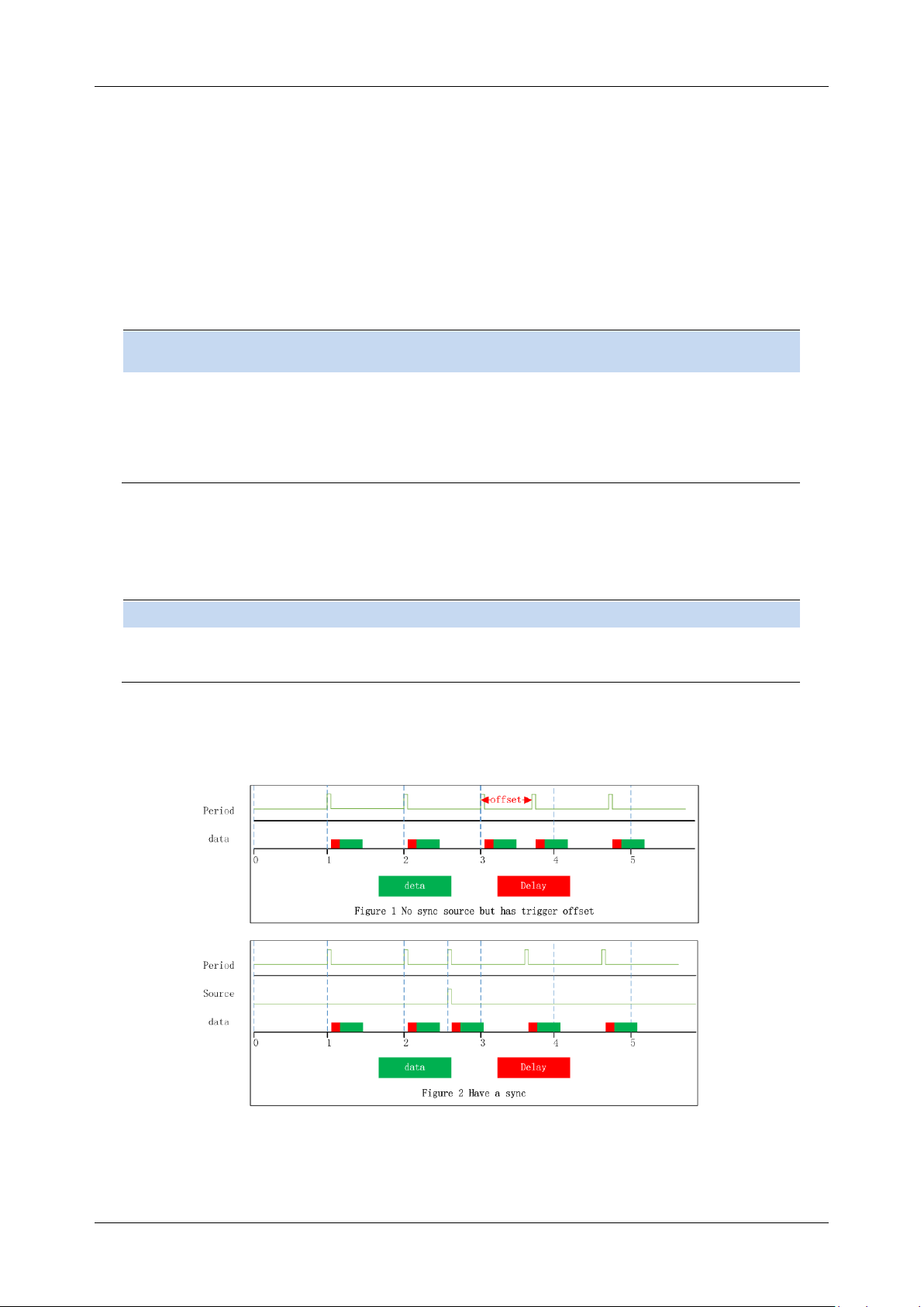
SHA850A User Manual
36 www.siglent.com
3.5.7 Offset Time
Adjust the cumulative offset between the periodic trigger clock and trigger events. The periodic trigger
clock cannot be viewed on the software, only the trigger event can be seen. Therefore, in order to
adjust the trigger event time, only the offset between the periodic triggering clock and the triggering
event can be adjusted. However, the absolute value of the internal offset is unknown, and each
modification of the offset is cumulative on the previous basis.
Command format
:TRIGger[:SEQuence]:FRAMe:OFFSet
:TRIGger[:SEQuence]:FRAMe:OFFSet?
Instructions
Set/Query Period Trigger period offset
Parameter Type
Float
Parameter Range
0s~10s
Return
Float
Example
:TRIGger:FRAMe:OFFSet 1s
3.5.8 Reset Time Offset Display
Reset the display of cycle trigger time offset.
Command format
:TRIGger[:SEQuence]:FRAMe:OFFSet:DISPlay:RESet
Instructions
Reset Period trigger offset return to zero
Example
:TRIGger:FRAMe:OFFSet:DISPlay:RESet
3.5.9 Sync Source (periodic trigger only)
Figure 3-1 Trigger of synchronization source
Page 61

SHA850A User Manual
www.siglent.com 37
Command format
:TRIGger[:SEQuence]:FRAMe:SYNC
:TRIGger[:SEQuence]:FRAMe:SYNC?
Instructions
Set/Query the type of periodic synchronization
Parameter Type
Enumeration
Parameter Range
"OFF", "EXT"
Return
"OFF", "EXT"
Example
:TRIGger:FRAMe:SYNC EXT
3.5.10 Gate Source
Select a gate source for gate measurement. The optional sources are external source and periodic
source.
External
Set the trigger source of the gate to be an external source. Similar to trigger, when configuring
external sources, you can choose whether to trigger on the rising edge or the falling edge, and
configure zero span delay compensation. The configuration of the gating source affects the
configuration of the trigger source.
Period
Set the trigger source of the gate to a periodic source. Similar to trigger, you can configure trigger
period, trigger offset, and trigger period synchronization sources when configuring periodic sources.
The configuration of the gating source affects the configuration of the trigger source.
Command format
[:SENSe]:SWEep:EGATe:SOURce
[:SENSe]:SWEep:EGATe:SOURce?
Instructions
Set or query the gate source type
Parameter Type
Enumeration
Parameter Range
" EXTernal ","FRAMe"
Return
"EXT","FRAMe"
Example
:SWEep:EGATe:SOURce EXT
3.5.11 Gate
The gate is to separate the spectrum information of some signals that occupy the same part in the
frequency domain but are separated from each other in the time domain, such as time division
multiple access signals.
3.5.11.1 Gate On
Turn on or off the gate function. When this function is enabled, the gate settings view is closed
Command format
[:SENSe]:SWEep:EGATe[:STATe]
[:SENSe]:SWEep:EGATe[:STATe]?
Instructions
Set or query the gate switch
Page 62

SHA850A User Manual
38 www.siglent.com
Parameter Type
Boolean
Parameter Range
0|1
Return
0|1
Example
:SWEep:EGATe 1
3.5.11.2 Gate Method
Configure the gate method.
⚫ LO gate: In this gate mode, the sweep does not start immediately, but detects the trigger of the
gate source first. After the trigger of the gate source, the gate signal is determined according to
the gate delay and gate width.
When the gate signal is high, the sweep begins. When the gate signal is low, sweep stops. When
the next gate trigger occurs, continue as before until the specified bandwidth has been swept.
In zero span mode, data is collected only when the gate is open, so the setting of the gate will
affect the actual sweep time, even though there is no actual sweep process.
⚫ FFT gate: In this gate mode, the sweep does not start immediately, but detects the trigger of the
gating source first. After the trigger of the gate source, the gate signal is determined according to
the gate delay and gate width.
When the gate signal is high, sweep starts, data is collected and FFT transformation is carried out.
Since the data processed by FFT needs to be continuous, the gate can be low only after FFT
transformation is completed, which is also why the gate length of FFT is a fixed value.
The gate length of FFT needs to be larger than the data length required to complete FFT. When
FFT completes a spectrum calculation, the gate will be lower. Then wait for the generation of the
next gate trigger and repeat the previous action until the specified bandwidth is swept. FFT gate
is unavailable in zero span mode.
⚫ Video gate: In this gate mode, after entering the sweep mode, it starts immediately and detects
the trigger of the gate source at the same time. After the trigger of the gate source, the gate signal
is determined according to the gate delay and the gate width.
When the gate signal is low, the output data is a constant value; when the gate signal is high, the
spectrum swept at this time is output. The video trigger does not affect the sweep process, but
displays the spectrum of the gate signal at the high moment, and a fixed value at other moments.
With this gate mode, it is usually necessary to set the sweep time to a long time so that the gate
signal appears at least once in each display point, thus ensuring that the detector can obtain the
real data in the corresponding time interval when the detect mode is peak detect.
Command format
[:SENSe]:SWEep:EGATe:METHod
[:SENSe]:SWEep:EGATe:METHod?
Instructions
Set/Query the gate method
Page 63
SHA850A User Manual
www.siglent.com 39
Parameter Type
Enumeration
Parameter Range
"OFF","LO","VIDeo","FFT"
Return
"OFF","LO","VIDeo","FFT"
Example
:SWEep:EGATe:METHod FFT
3.5.11.3 Gate Length
Set the gate length.This parameter cannot be changed when FFT gate.
The relationship between RBW and gate length in FFT gate mode
RBW
gate length (us)
1Hz
2498064
3Hz
828368
10Hz
272348
30Hz
86968
100Hz
27807
300Hz
10323
1000Hz
5447
3000Hz
2333
10000Hz
1117
Command format
[:SENSe]:SWEep:EGATe:LENGth
[:SENSe]:SWEep:EGATe:LENGth?
Instructions
Set/Query the gate length
Parameter Type
Float
Parameter Range
2.106us~5s
Return
Float
Example
:SWEep:EGATe:LENGth 1s
3.5.11.4 Gate Delay
Configure the delay between gate trigger and gate on.
Command format
[:SENSe]:SWEep:EGATe:DELay
[:SENSe]:SWEep:EGATe:DELay?
Instructions
Set or query the gate delay
Parameter Type
Float
Parameter Range
Swept : 8.906us~25s
Zero span : 1.894us~25s
Return
Float
Example
SWEep:EGATe:DELay 0.005s
Page 64
SHA850A User Manual
40 www.siglent.com
3.5.11.5 Gate View
When Turn on this view:
⚫ Disable the gate on/off and the gate function.
⚫ To enter the zero span mode, set different Gate View Sweep Time based on different gate
methods.When you close the gate view, the sweep span and sweep time before the gate view is
enabled are restored.
Gate View Sweep Time
Controls the sweep time in the gate view window. When selecting different gate methods, the
instrument will automatically configure different sweep time.
Gate View Start Time
Set the start time on the left of the gate view, that is, set a delay.
Command format
[:SENSe]:SWEep:EGATe:VIEW
[:SENSe]:SWEep:EGATe:VIEW?
Instructions
Set or query the gate view switch
Parameter Type
Boolean
Parameter Range
0|1
Return
0|1
Example
:SWEep:EGATe:VIEW 1
Command format
[:SENSe]:SWEep:EGATe:VIEW:STARt
[:SENSe]:SWEep:EGATe:VIEW:STARt?
Instructions
Set/Query the gate View start time
Parameter Type
Float
Return
Float
Example
:SWEep:EGATe:VIEW:STARt 1s
Command format
[:SENSe]:SWEep:EGATe:TIME
[:SENSe]:SWEep:EGATe:TIME?
Instructions
Set/Query the gate View time
Parameter Type
Float
Return
Float
Example
[:SENSe]:SWEep:EGATe:TIME 1s
Page 65
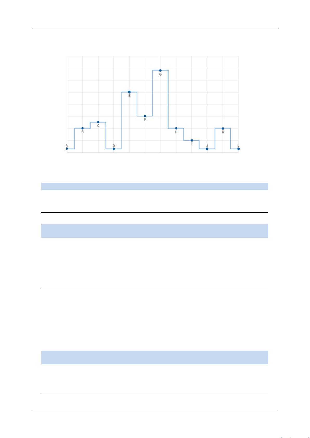
SHA850A User Manual
www.siglent.com 41
3.6 Trace
Figure 3-2 trace select
The sweep signal is displayed as a trace on the screen.
Command format
:TRACe[1]|2|3|4|5|6 [:DATA]?
Instructions
Get trace data
Return
String
Example
:TRACe:DATA?
Command format
:FORMat[:TRACe][:DATA]ASCii|REAL32| REAL
:FORMat[:TRACe][:DATA]?
Instructions
Sets/gets the format of trace data read
Parameter Type
Enumeration
Parameter Range
ASCii
REAL32 Floating 32 bit
REAL Floating 64 bit
Return
Enumeration : ASCii|REAL| REAL32
Example
:FORMat ASCii
3.6.1 Select Trace
The analyzer allows for up to four traces to be displayed at the same time. Each trace has its own
color (Trace A - Yellow, Trace B - Purple, Trace C - Light blue and Trace D - Green). All traces can be
set parameter independently. As a default, analyzer will choose Trace A and set the type of the trace
as Clear Write.
Command format
TRACe:SELEct
TRACe:SELEct?
Instructions
Sets/gets the current trace
Parameter Type
EnumerationTRACE1-6
Return
Enumeration : TRACE1-6
Example
TRACe:SELEct TRACE3
Page 66

SHA850A User Manual
42 www.siglent.com
3.6.2 Trace Type
Set the type of the current trace or disable it. The system calculates the sampled data using a specific
operation method according to the trace type selected and displays the result. Trace types include
Clear Write, Max Hold, Min Hold, View, Average and Blank. The corresponding icon of the trace type
will be displayed in the status bar at the left of the screen, as shown in the figure below.
Clear Write
Erases any data previously stored in the selected trace, and display the data sampled in real-time of
each point on the trace.
Max Hold
Retain the maximum level for each point of the selected trace. Update the data if a new maximum
level is detected in successive sweeps. Max Hold is very effective when measuring events that may
take successive scans to measure accurately. Some common applications include FM Deviation, AM
NRSC, and frequency hopping or drift.
Min Hold
Display the minimum value from multiple sweeps for each point of the trace and update the data if a
new minimum is generated in successive sweeps.
Average
Set the averages times of the selected trace.
More averages can reduce the noise and the influence of other random signals; thus highlighting the
stable signal characteristics. The larger the averages times is, the smoother the trace will be. Enabling
averaging will take more time to collect the full spectral information because the analyzer needs to
sweep the set average count. The displayed data is averaged in a first-in-first-out fashion.
Command format
:TRACe[1]|2|3|4|5|6:TYPE WRITe|MAXHold|MINHold| AVERage
:TRACe[1]|2|3|4|5|6:TYPE?
Instructions
Sets/gets the display type of trace
Parameter Type
Enumeration
Parameter Range
WRITe : Trace is in normal mode. Update data
MAXHold : Displays the maximum value of traces
MINHold : Displays the minimum value of trace
AVERage : Displays the average value of trace
Return
Enumeration : WRITE|MAXH|MINH| AVER
Example
:TRAC1:TYPE MINH
3.6.3 Trace State
There are four trace states: active, view, blank, and background. Different trace states indicate the
refresh and display states of traces:
Active
Refreshed and displayed trace data.
Page 67

SHA850A User Manual
www.siglent.com 43
View
The trace data will not be refreshed, and the current latest trace will be displayed in a fixed frame.
Blank
Trace data is no longer refreshed or displayed
Background
Refreshed trace data but no display.
Command format
:TRACe[1]|2|3|4|5|6:DISPlay[:STATe]
:TRACe[1]|2|3|4|5|6:DISPlay[:STATe]?
Instructions
Sets/gets the display status of the trace
Parameter Type
Enumeration : ACTI|VIEW|BLAN| BACK
Parameter Range
ACTIve : Trace is in normal mode. Update data
VIEW : Stops updating trace to display current trace data
BLANk : Clear trace data
BACKground : Set as background
Return
Enumeration : ACTI|VIEW|BLAN| BACK
Example
:TRACe2:DISPlay BLANK
:TRACe2:DISPlay?
3.6.4 Detect
The analyzer displays the sweep signal on the screen in the form of a trace. For each trace point, the
analyzer always captures all the data within a specific time interval and processes (Peak, Average,
etc.) the data using the detector currently selected, then it displays the processed data (a single data
point) on the screen.
Select an appropriate detector type according to the actual application in order to ensure the accuracy
of the measurement.
The available types are Pos Peak, Neg Peak, Sample, Normal, Average and Quasi Peak. The
default is Pos peak.
Positive Peak
For each trace point, Positive Peak detector displays the maximum value of data sampled within the
corresponding time interval.
Negative Peak
For each trace point, Negative Peak detector displays the minimum value of data sampled within the
corresponding time interval.
Sample
For each trace point, Sample detector displays the transient level corresponding to the central time
point of the corresponding time interval. This detector type is applicable to noise or noise-like signal.
Normal
Page 68

SHA850A User Manual
44 www.siglent.com
Normal detector (also called ROSENFELL Detector) displays the maximum value and the minimum
value of the sample data segment in turn: Odd-numbered data points display the maximum value and
even-numbered data points display the minimum value. In this way, the amplitude variation range of
the signal is clearly shown.
Average
For each trace point, Average detector displays the average value of data sampled within the
corresponding time interval.
Command format
[:SENSe]:DETector:TRACe[1]|2|3|4|5|6[:FUNCtion]
[:SENSe]:DETector:TRACe[1]|2|3|4|5|6[:FUNCtion]?
Instructions
Sets/Gets the trace detection type
Parameter Type
Enumeration NEG|POS|SAMP|AVER|NORMAL
Parameter Range
NORMAL : standard
NEGative : Negative peak
POSitive : positive peak
SAMPle : The sampling
AVERage : average,
Return
Enumeration : NEG|POS|SAMP|AVER|NORMAL
Example
:DETector:TRAC1 AVERage
Command format
[:SENSe]:DETector:TRACe[1]|2|3|4|5|6:AUTO 0|1
[:SENSe]:DETector:TRACe[1]|2|3|4|5|6:AUTO?
[:SENSe]:DETector:TRACe:AUTO:ALL
Instructions
Set/get trace automatic detection switch
Parameter Type
Boolean
Parameter Range
0|1
Return
0|1
Example
:DETector:TRACe3:AUTO 1
:DETector:TRACe:AUTO:ALL
3.6.5 Math
Set the computational method of the math trace.
Output Z
The Math result is denoted by the Z variable and can be displayed by trace
Input X, Y
Input X, Y can be applied to trace
Calculation Type
The analyzer provides the calculation types as shown below:
Power Diff : X-Y+Offset→Z
Power Sum : X+Y+Offset→Z
Page 69

SHA850A User Manual
www.siglent.com 45
Log Offset : X+ Offset→Z
Log Diff : X-Y-Ref→Z
Offset value
Command format
:TRACe[1]|2|3|4|5|6:MATH:X
:TRACe[1]|2|3|4|5|6MATH:X?
Instructions
Sets/gets the x-trace of the variable
Parameter Type
Enumeration
Parameter Range
TRACE1-6
Return
Enumeration
Example
:TRACe3:MATH:X 5
Command format
:TRACe:MATH:Y [1]|2|3|4|5|6
:TRACe:MATH:Y?
Instructions
Set the variable Y trace
Get the variable y-trace
Parameter Type
Enumeration
Parameter Range
TRACE1-6
Return
Enumeration
Example
:TRACe1:MATH:Y 3
Command format
:CALCulate[:SELected]:MATH:FUNCtion
:CALCulate[:SELected]:MATH:FUNCtion?
Instructions
Sets/gets the trace calculation type
Parameter Type
Enumeration
Parameter Range
OFF
PDIF : Power subtracting
PSUM : Power up
LOFF : Logarithmic deviation
LDIF : Logarithmic subtraction
Return
Enumeration
Example
:CALCulate:MATH:FUNCtion PDIF
Command format
:TRACe[1]|2|3|4|5|6:MATH:OFFSet
:TRACe[1]|2|3|4|5|6:MATH:OFFSet?
Instructions
Set the LOG OFFSET constant
Ask for the LOG OFFSET constant
Parameter Type
Integer
Parameter Range
-100dB-100dB
Return
-100dB-100dB
Example
:TRACe1:MATH:OFFSet -10
:TRACe3:MATH:OFFSet?
Command format
:TRACe[1]|2|3|4|5|6:MATH:REFerence
:TRACe[1]|2|3|4|5|6:MATH:REFerence?
Instructions
Sets/gets the LOG DIFF constant
Page 70

SHA850A User Manual
46 www.siglent.com
Parameter Type
Integer
Parameter Range
-100dB-100dB
Return
-100dB-100dB
Example
:TRACe5:MATH:REFerence 10
:TRACe6:MATH:REFerence?
3.6.6 Normalize
Trace normalization function. Please save the reference trace before using this function.
Command format
:CALCulate:NTData:STORE:REF
Instructions
Set normalization to save the reference trace
Example
:CALCulate:NTData:STORE:REF
Command format
:CALCulate:NTData[:STATe] OFF|ON|0|1
:CALCulate:NTData[:STATe]?
Instructions
Set/read switch normalization
Parameter Type
Boolean
Parameter Range
0|1
Return
0|1
Example
:CALCulate:NTData 1
Command format
:DISPlay:WINDow:TRACe:Y[:SCALe]:NRLevel
:DISPlay:WINDow:TRACe:Y[:SCALe]:NRLevel?
Instructions
Sets/gets the normalized reference level
Parameter Type
Float , unitdB
Parameter Range
-200 dB ~ 200 dB
Return
Float , unitdB
Example
:DISPlay:WINDow:TRACe:Y:NRLevel 10
Command format
:DISPlay:WINDow:TRACe:Y[:SCALe]:NRPosition
:DISPlay:WINDow:TRACe:Y[:SCALe]:NRPosition?
Instructions
Sets/reads the normalized reference location
Parameter Type
Integer
Parameter Range
0 ~ 100
Return
Integer
Example
:DISPlay:WINDow:TRACe:Y:NRPosition 10
Command format
:DISPlay:WINDow:NTTRace[:STATe]
:DISPlay:WINDow:NTTRace[:STATe]?
Instructions
Sets/gets the normalized reference trace switch
Parameter Type
Boolean
Parameter Range
0|1
Return
0|1
Example
:DISPlay:WINDow:NTTRace 1
Page 71

SHA850A User Manual
www.siglent.com 47
3.6.7 Trace Function
Trace function supports the following operations on the specified trace
Trace Copy
Copy data from the source trace to the destination trace. After copying, the trace state of the target
trace is automatically changed to view.
Trace Exchange
Exchange the data of the source trace with the data of the target trace. After the exchange, the trace
status of the source trace and the target trace will be automatically changed to view.
Preset All Traces
The settings and data of all traces are changed to the default state.
Clear All Traces
Clear all traces data.
Command format
:TRACe:COPY
Instructions
Copy the trace
Example
:TRACe:COPY 1,2
Command format
:TRACe:EXCHange
Instructions
Exchange of trace
Example
:TRACe:EXCHange 1,2
Command format
:TRACe:PRESet:ALL
Instructions
Reset all traces
Example
:TRACe:PRESet:ALL
Command format
:TRACe:CLEar:ALL
Instructions
Clear all traces
Example
:TRACe:CLEar:ALL
3.7 Marker & Peak
The marker appears as a rhombic sign (as shown below) for identifying points on a trace. You can
easily read the amplitude, frequency and sweep time of the marked point on the trace.
⚫ The analyzer allows for up to eight/four pairs of markers to be displayed at one time, but only one
pair or a single marker is active every time.
⚫ You can use the numeric keys, knob or direction keys to modify the desired frequency or time as
well as view the readouts of different points on the trace.
Page 72

SHA850A User Manual
48 www.siglent.com
3.7.1 Select Marker
Select one of the eight markers. The default is Marker1. When a marker is selected, you can set its
type, trace to be marked, readout type and other related parameters. The enabled marker will appear
on the trace selected through the Select Trace option and the readouts of this marker are also
displayed in the active function area and at the upper right corner of the screen.
Command format
:CALCulate:MARKer:SELEct
:CALCulate:MARKer:SELEct?
Instructions
Sets/Gets the current marker
Parameter Type
Enumeration1-8
Return
Enumeration : 1-8
Example
:CALCulate:MARKer:SELEct 5
3.7.2 Select Trace
Select the trace to be marked by the current marker. Valid selections includeTrace1,2,3,4,5,6.
Command format
:CALCulate:MARKer[1]|2|3|4|5|6|7|8:TRACe 1|2|3|4|5|6
:CALCulate:MARKer[1]|2|3|4|5|6|7|8:TRACe?
Instructions
Sets/Gets the marker trace
Parameter Type
Enumeration
Parameter Range
1|2|3|4|5|6
Return
Enumeration
Example
CALCulate:MARK:TRAC 1
3.7.3 Marker Type
3.7.3.1 Normal
One of the marker types. It is used to measure the X (Frequency or Time) and Y (Amplitude) values of
a certain point on the trace. When selected, a marker with the number of the current marker (such as
“ 1 ”) appears on the trace.
⚫ If no active marker exists currently, a marker will be enabled automatically at the center frequency
of the current trace.
⚫ You can use the numeric keys, knob or direction keys to move the marker. The readouts of the
marker will be displayed at the upper right corner of the screen.
⚫ The readout resolution of the X-axis (frequency or time) is related to the span. For higher readout
resolution, reduce the span.
3.7.3.2 Delta
One of the marker types. It is used to measure the delta values of X (Frequency or Time) and Y
(Amplitude) between the reference point and a certain point on the trace. When selected, a pair of
Page 73

SHA850A User Manual
www.siglent.com 49
markers appears on the trace: Fixed Related Marker (marked by a combination of the marker number
and letter “ + ”, such as “ 2+ ”) and the Delta Marker (marked by the “∆”, such as “ 1∆2 ”).
⚫ After the marker selects “Delta”, the original marker will become the delta measurement marker,
and the related marker of the incrementing sequence number will become the reference “fixed”
marker
⚫ The delta marker is in the "relative to" state, and its X-axis position can be changed; the related
marker is in the "fixed" state by default (the X-axis and Y-axis positions are fixed), but the X-axis
can be adjusted by changing to the "normal" state.
⚫ The first row in the upper right corner of the trace area shows the frequency (or time) difference
and amplitude difference between the two markers; the second row in the upper right corner of
the trace area shows the X axis and amplitude value of the related marker.
⚫ Delta reset. It is only valid when the current marker is a differential marker. If the marker type of
the relative marker of the current marker is normal or differential, change the horizontal position of
the relative marker to the horizontal position of the current marker; if the marker type of the
relative marker is fixed, change the horizontal position and vertical position of the relative marker
to the current one. The horizontal and vertical position of the marker.
3.7.3.3 Fixed
One of the marker types. When “Fixed” is selected, the X-axis and Y-axis of the marker will not
change by the trace and can only be changed through the menu. The fixed marker is marked with "+".
After the marker selects “Delta”, the original marker will become the delta measurement marker, and
the related marker of the incrementing sequence number will become the reference “fixed” marker
3.7.3.4 Off
Turn off the marker currently selected. The marker information displayed on the screen and functions
based on the marker will also be turned off.
Command format
:CALCulate:MARKer[1]|2|3|4|5|6|7|8:MODE POSition|DELTa|FIXed|OFF
:CALCulate:MARKer[1]|2|3|4:MODE?
Instructions
Sets/Gets the marker mode
Parameter Type
Enumeration
Parameter Range
POSition
DELTa
FIXed
OFF
Return
Enumeration : POS|DELT|FIX|OFF
Example
:CALCulate:MARK1:MODE POSition
Command format
:CALCulate:MARKer[1]|2|3|4|5|6|7|8:STATe OFF|ON|0|1
:CALCulate:MARKer[1]|2|3|4|5|6|7|8:STATe?
Instructions
Sets/gets the marker switch status
Parameter Type
Boolean
Page 74

SHA850A User Manual
50 www.siglent.com
Parameter Range
OFF|ON|0|1
Return
0|1
Example
:CALCulate:MARK1:STATe ON
Command format
:CALCulate:MARKer:AOFF
Instructions
Close all markers
Example
:CALCulate:MARKer:AOFF
Command format
:CALCulate:MARKer[1]|2|3|4|5|6|7|8 [:SET]:RESEt:DELTa
Instructions
Difference marker resets to 0
Only valid when the current cursor is a differential marker
Example
:CALCulate:MARKer2:RESEt:DELTa
3.7.4 Marker Postion
Displays and sets the position of the marker. Only the x-axis position can be set.
Command format
:CALCulate:MARKer[1]|2|3|4|5|6|7|8:X
:CALCulate:MARKer[1]|2|3|4|5|6|7|8:X?
Instructions
Sets/gets the value of the marker point X axis
This command takes effect only when the marker mode is not OFF:
:CALCulate:MARKer[1]|2|3|4|5|6|7|8:STATe
:CALCulate:MARKer[1]|2|3|4|5|6|7|8:MODE
If the marker readout type is frequency, the parameter is frequency.
When the marker readout type is time, the value is time. Reference
commands::CALCulate:MARKer[1]|2|3|4|5|6|7|8:X:READout
Parameter Type
frequency , Float , unitHz , kHz , MHz , GHz , default Hz
or time , Float , unitus , ms , s , ks , default s
Parameter Range
0 Hz ~ max span or 10 ms ~ 1000 s
Return
When the marker readout type is frequency, the reading is frequency, floating
point type, in Hz;
When the marker readout type is time, the reading is time, floating point type, in s;
When the marker readout type is cycle, the reading is cycle, floating point type,
unit s;
Example
:CALCulate:MARKer4:X 0.4 GHz
:CALCulate:MARKer4:X 200 ms
:CALCulate:MARKer4:X?
Command format
:CALCulate:MARKer[1]|2|3|4|5|6|7|8:Y
:CALCulate:MARKer[1]|2|3|4|5|6|7|8:Y?
Instructions
Read the value of the Y-axis of the marker point, which can also be used to read
the marker noise in the marker function.
To execute this command, ensure that the marker is in the
onstate.:CALCulate:MARKer[1]|2|3|4|5|6|7|8:STATe
:CALCulate:MARKer[1]|2|3|4|5|6|7|8:MODE
Parameter Type
Float
Parameter Range
None
Return
Float , unitdBm
Example
:CALCulate:MARKer1:Y?
Return : -25
Page 75

SHA850A User Manual
www.siglent.com 51
3.7.5 Relative To
“Relative to” is used to measure the delta values of X (Frequency or Time) and Y (Amplitude) between
two markers which can mark on different traces.
After the marker selects “Delta”, the original marker will become the delta measurement marker, and
the related marker of the incrementing sequence number will become the reference “fixed” marker
Command format
:CALCulate:MARKer[1]|2|3|4|5|6|7|8:REFerence 1|2|3|4
:CALCulate:MARKer[1]|2|3|4|5|6|7|8:REFerence?
Instructions
Sets/Gets the marker relative to
Parameter Type
Enumeration
Parameter Range
1|2|3|4|5|6|7|8
Return
Enumeration
Example
:CALCulate:MARKer1:REFerence 3
3.7.6 Readout Type
Select a desired readout type for the X-axis for the marker. Different markers can use different readout
types. This setting will change the readout type and affect the marker readings in the active function
area and at the upper right corner of the screen, but will not change the actual value.
Frequency
In this type, Normal marker shows the absolute frequency. Delta markers and Delta Pair markers
show the frequency difference between the delta marker and reference marker. The default readout
mode in non-zero span is “Frequency”.
Note: This type is invalid in Zero span.
Period
In this type, the Normal marker shows the reciprocal of frequency; while Delta marker and Delta Pair
marker show the reciprocal of frequency difference. When the frequency difference is zero, the
reciprocal is infinite and 100 Ts is displayed.
Note: This type is invalid in Zero span.
Time
In this type, the Normal marker shows the time difference between the marker and the start of the
sweep; while Delta marker and Delta Pair marker show the sweep time difference between the delta
marker and reference marker.
The default readout mode in Zero span is Time.
Page 76

SHA850A User Manual
52 www.siglent.com
Inverse Time
In this type, the Normal marker Inverse Time = 1 / Time; while Delta marker and Delta Pair marker s
Inverse Time = 1 / Δ Time.
Command format
:CALCulate:MARKer[1]|2|3|4|5|6|7|8:X:READout
FREQuency | TIME | PERiod | INTIme
:CALCulate:MARKer[1]|2|3|4|5|6|7|8:X:READout?
Instructions
Sets/gets the marker in X-axis reading mode
Parameter Type
Enumeration
Parameter Range
FREQuency , frequency
TIME
PERiod
INVERSE_TIME
Return
Enumeration: FREQ|TIME|PER| INTIme
Example
:CALCulate:MARKer1:X:READout FREQuency
Command format
:CALCulate:MARKer[1]|2|3|4|5|6|7|8:X:READout:AUTO 0|1
:CALCulate:MARKer[1]|2|3|4|5|6|7|8:X:READout:AUTO?
Instructions
Sets/gets the marker in X-axis reading mode auto
Parameter Type
Boolean
Parameter Range
OFF|ON|0|1
Return
0|1
Example
:CALCulate:MARKer1:X:READout:AUTO 1
3.7.7 Marker Couple
When Marker Couple is on, Markers are set up and moved in coupled operation on all traces.
When Marker Couple is off, Markers are set up and moved independently for each trace.
Command format
:CALCulate[:SELected]:MARKer:COUPle
:CALCulate[:SELected]:MARKer:COUPle?
Instructions
Set/query the marker coupling switch
Parameter Type
Boolean
Parameter Range
ON|OFF|0|1
Return
0|1
Example
:CALCulate:MARKer:COUPle 1
:CALCulate:MARKer:COUPle?
3.7.8 Marker Lines
Mark the marker with the intersection of horizontal and vertical lines, which is more convenient to
query the marker position in the waveform area.
Page 77

SHA850A User Manual
www.siglent.com 53
Command format
:CALCulate:MARKer[1]|2|3|4|5|6|7|8:X:LINE:STATe
:CALCulate:MARKer[1]|2|3|4|5|6|7|8:X:LINE:STATe?
Instructions
Sets/gets the marker line switch
Parameter Type
Boolean
Parameter Range
ON|OFF|0|1
Return
0|1
Example
:CALCulate:MARKer2:X:LINE:STATe 1
:CALCulate:MARKer2:X:LINE:STATe?
3.7.9 Marker Table
Enable or disable the Marker Table.
Display all the markers enabled on the lower portion of the screen, including marker number, trace
number, marker readout type, X-axis readout and amplitude. Through this table you can view the
measurement values of multiple points. The table allows for up to eight markers to be displayed at one
time.
Command format
:CALCulate:MARKer:TABLe ON|OFF|0|1
:CALCulate:MARKer:TABLe?
Instructions
Sets/gets the marker table state
Parameter Type
Boolean
Parameter Range
ON|OFF|0|1
Return
0|1
Example
:CALCulate:MARKer:TABLe ON
3.7.10 Marker ->
3.7.10.1 M->CF
Set the center frequency of the analyzer to the frequency of the current marker.
⚫ If the Normal marker is selected, the center frequency will be set to the frequency of the current
marker.
⚫ If the Delta or Delta Pair marker is selected, the center frequency will be set to the frequency of
the Delta Marker.
⚫ The function is invalid in Zero span.
Command format
:CALCulate:MARKer[1]|2|3|4|5|6|7|8[:SET]:CENTer
Instructions
Sets/gets the value of the marker X axis to the center frequency .If the marker is
not open, this command automatically turns the marker on the center frequency.
Example
:CALCulate:MARKer1:CENTer
Page 78

SHA850A User Manual
54 www.siglent.com
3.7.10.2 M -> CF Step
Set the center frequency step of the analyzer to the frequency of the current marker.
⚫ If the Normal marker is selected, the center frequency step will be set to the frequency of the
current marker.
⚫ If the Delta or Delta Pair marker is selected, the center frequency step will be set to the frequency
of the Delta Marker.
⚫ The function is invalid in Zero span.
Command format
:CALCulate:MARKer[1]|2|3|4|5|6|7|8[:SET]:STEP
Instructions
Sets/gets the value of the marker X axis to mid-frequency step
If the marker is not open, this command automatically turns the marker on the
center frequency.
Example
:CALCulate:MARKer1:STEP
3.7.10.3 M -> Start Freq
Set the start frequency of the analyzer to the frequency of the current marker.
⚫ If the Normal marker is selected, the start frequency will be set to the frequency of the current
marker.
⚫ If the Delta or Delta Pair marker is selected, the start frequency will be set to the frequency of the
Delta Marker.
⚫ The function is invalid in Zero span.
Command format
:CALCulate:MARKer[1]|2|3|4|5|6|7|8[:SET]:START
Instructions
Sets/gets the value of the marker X axis to the starting frequency, valid when the
marker is on
Example
:CALCulate:MARKer1:START
3.7.10.4 M -> Stop Freq
Set the stop frequency of the analyzer to the frequency of the current marker.
⚫ If the Normal marker is selected, the stop frequency will be set to the frequency of the current
marker.
⚫ If the Delta or Delta Pair marker is selected, the stop frequency will be set to the frequency of the
Delta Marker.
⚫ The function is invalid in Zero span.
Command format
:CALCulate:MARKer[1]|2|3|4|5|6|7|8[:SET]:STOP
Instructions
Sets/gets the value of the marker X axis to terminate frequency
If the corresponding marker is not open, sending this command will automatically
open the marker at the end frequency.
Example
:CALCulate:MARKer1:STOP
Page 79

SHA850A User Manual
www.siglent.com 55
3.7.10.5 M ->Ref Level
Set the reference level of the analyzer to the amplitude of the current marker.
⚫ If the Normal marker is selected, the reference level will be set to the amplitude of the current
marker.
⚫ If the Delta or Delta Pair marker is selected, the reference level will be set to the amplitude of the
Delta Marker.
Command format
:CALCulate:MARKer[1]|2|3|4|5|6|7|8[:SET]:RLEVel
Instructions
Sets/gets the value of the marker Y-axis as a reference level
If the marker is not open, this command automatically turns the marker on the
center frequency.
Example
:CALCulate:MARKer2:RLEVel
3.7.10.6 ΔM->Span
Set the span of the analyzer to the frequency difference between the two markers in Delta marker
type.
⚫ If the Normal marker is selected, this function is invalid.
⚫ The function is invalid in Zero span.
Command format
:CALCulate:MARKer[1]|2|3|4|5|6|7|8:DELTa[:SET]:SPAN
Instructions
Sets/gets the difference between the marker and the X axis to sweep width
This command takes effect only when the marker mode is DELTa
:CALCulate:MARKer[1]|2|3|4|5|6|7|8:MODE
Example
:CALCulate:MARKer2:DELTa:SPAN
3.7.10.7 ΔM->CF
Set the center frequency of the analyzer to the frequency difference between the two markers in Delta
marker type.
⚫ If the Normal marker is selected, this function is invalid.
⚫ The function is invalid in Zero span.
Command format
:CALCulate:MARKer[1]|2|3|4|5|6|7|8:DELTa[:SET]:CENTer
Instructions
Sets/gets the difference between the marker and the X axis to the center
frequency
This command takes effect only when the marker mode is DELTa
:CALCulate:MARKer[1]|2|3|4|5|6|7|8:MODE
Example
:CALCulate:MARKer3:DELTa:CENTer
3.7.11 Marker Fn
Special marker functions including Noise Marker, N dB BW and Freq Counter.
Command format
:CALCulate:MARKer[1]|2|3|4|5|6|7|8:FUNCtion OFF|FCOunt|NOISe|NDB
:CALCulate:MARKer[1]|2|3|4|5|6|7|8:FUNCtion?
Page 80
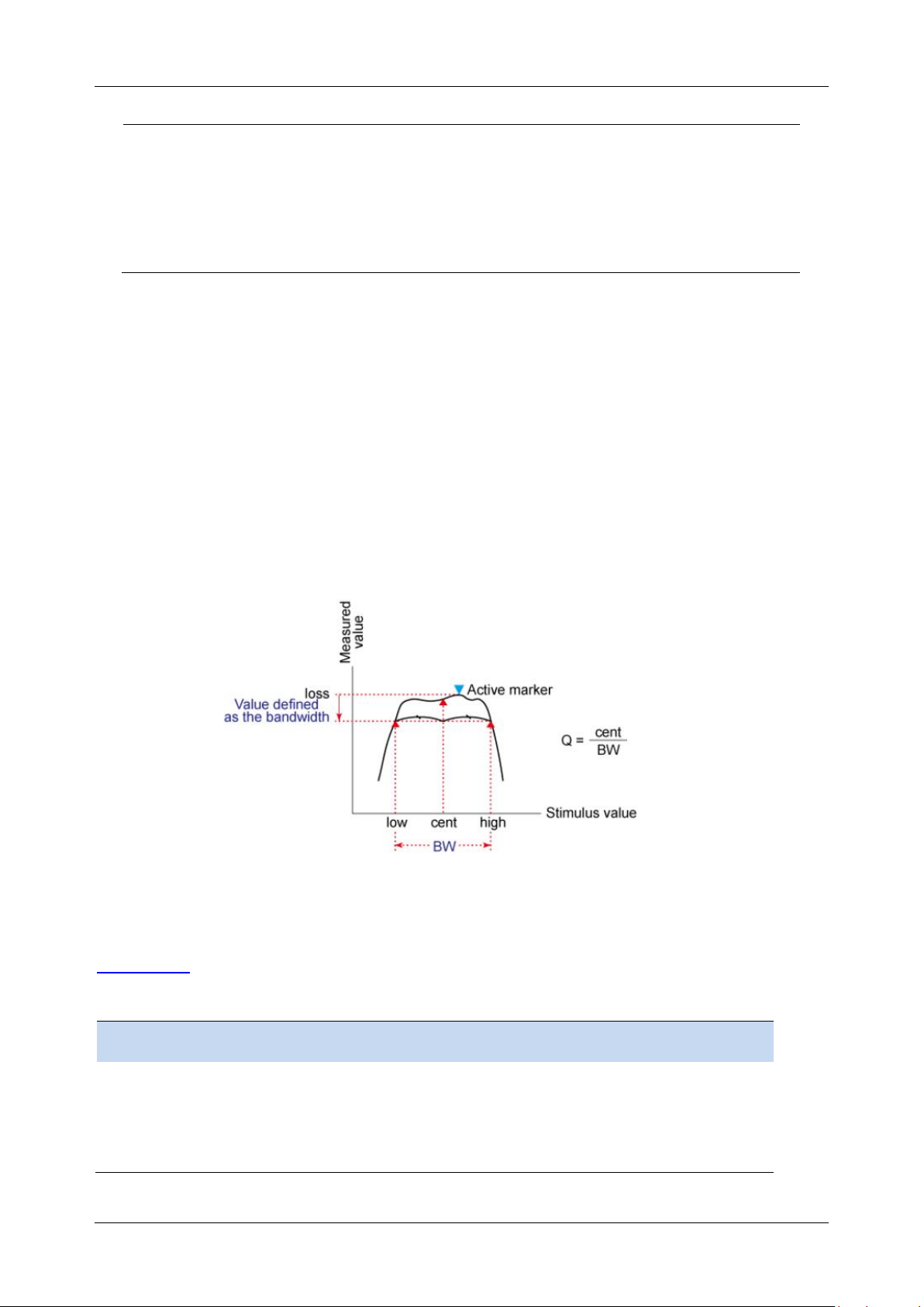
SHA850A User Manual
56 www.siglent.com
Instructions
Set/Get marker function
Parameter Type
Enumeration
Parameter Range
OFF : normal
NOISe : noisy marker
NDB : N dB marker
Return
Enumeration: OFF|NOISe|NDB
Example
:CALCulate:MARK1:FUNCtion NOISe
3.7.11.1 N dB BW
Enable the N dB BW measurement or set the value of N dB. The N dB BW denotes the frequency
difference between two points that are located on both sides of the current marker and with N dB fall
(N Less than or equal to 0) or rise (N>0) in amplitude as shown in the figure on the next page.
When the measurement starts, the analyzer will search for the two points which are located at both
sides of the current point with N dB fall or rise in amplitude and display the frequency difference
between the two points in the active function area. "----" would be displayed if the search fails.
The parameters in the figure are shown as :
Figure 3-3 N dB parameter
mkr_ndb_bw
Command format
:CALCulate:MARKer[1]|2|3|4|5|6|7|8:BANDwidth:NDB
:CALCulate:MARKer[1]|2|3|4|5|6|7|8:BANDwidth:NDB?
Instructions
Set/Obtain the N dB bandwidth reference value
Parameter Type
Float
Parameter Range
-100 dB ~ 100 dB
Return
Float
Example
:CALCulate:MARK1:BANDwidth:NDB 10 DB
Page 81
SHA850A User Manual
www.siglent.com 57
Command format
:CALCulate:MARKer[1]|2|3|4|5|6|7|8:BANDwidth:RESult?
Instructions
Result of setting/reading N dB bandwidth
Return
Float
Example
:CALCulate:MARK1:BANDwidth:RESult?
3.7.11.2 Freq Counter
Turn on or off the frequency counter. The frequency readout is accuracy is up to 0.01 Hz.
⚫ The function is valid only when selecting marker 1.
⚫ If marker 1 is selected but not active, turning on the frequency counter will open marker 1 Normal
marker automatically.
⚫ The frequency counter measures the frequency near the center frequency in Zero span.
Command format
:CALCulate:MARKer[1]|2|3|4|5|6|7|8:FCOunt:[:STATe] ON|OFF|0|1
:CALCulate:MARKer[1]|2|3|4|5|6|7|8:FCOunt:[:STATe]?
Instructions
Sets/gets the marker frequency counter state
Parameter Type
Boolean
Parameter Range
ON|OFF|0|1
Return
0|1
Example
:CALCulate:MARK1:FCOunt 1
Command format
:CALCulate:MARKer[1]|2|3|4|5|6|7|8:FCOunt:X?
Instructions
Read the marker frequency counter reading
Return
Float
Example
:CALCulate:MARK1:FCOunt:X?
3.7.11.3 Noise Marker
Execute the Noise marker function for the selected marker and read the normalized noise power
spectral density.
⚫ If the current marker is “ Off ” in the Marker menu, pressing Noise Marker will first set it to Normal
type automatically; then measure the average noise level at the marked point and normalize this
value to 1 Hz bandwidth. During this process, certain compensation is always made based on the
detection and trace types. The measurement will be more precise if RMS Avg or Sample
detection type is used.
⚫ This function can be used for measuring the C/N ratio.
3.7.11.4 Off
Turn off the noise marker, N dB BW measurement or Frequency Counter, but not the marker itself.
Page 82

SHA850A User Manual
58 www.siglent.com
3.7.12 Peak Search
Open the peak search setting menu and execute peak search.
3.7.12.1 Peak Search
Next Search
Execute peak search and mark the peak.
Minium Peak
Execute minimum search and mark the minium peak.
Next Peak
Search for and mark the peak whose amplitude is closest to that of the current peak and which meets
the peak search condition.
Next Left Peak
Search for and mark the nearest peak which is located at the left side of the current peak and meets
the peak search condition.
Next Right Peak
Search for and mark the nearest peak which is located at the right side of the current peak and meets
the peak search condition.
Peak Peak
Execute peak search and minimum search at the same time and mark the results with delta pair
markers. Wherein, the result of peak search is marked with the delta marker and the result of
minimum search is marked with the reference marker.
Peak -> CF
Execute peak search and set the center frequency of the analyzer to the frequency of the peak.The
function is invalid in Zero Span.
Command format
:CALCulate:MARKer[1]|2|3|4|5|6|7|8:MAXimum
Instructions
Marker searches for peaks and marks them with the specified marker
(If peak-to-peak value is on, peak-to-peak value search is carried out; otherwise,
single peak value search is carried out, refer to the
command:CALCulate:MARKer[1]|2|3|4|5|6|7|8:PTPeak:STATe
Search criteria include peak type, absolute threshold, and relative offset
:CALCulate:MARKer:PEAK:SEARch:MODE
:CALCulate:MARKer:PEAK:THReshold
:CALCulate:MARKer:PEAK:EXCursion)
Example
:CALCulate:MARKer4:MAXimum
Command format
:CALCulate:MARKer[1]|2|3|4|5|6|7|8:MINimum
Instructions
Marker searches for the minimum peak and marks it with the specified marker
Example
:CALCulate:MARKer4:MINimum
Page 83

SHA850A User Manual
www.siglent.com 59
Command format
:CALCulate:MARKer[1]|2|3|4|5|6|7|8:MAXimum:NEXT
Instructions
Marker searches for the next peak and marks it with the specified marker
(Based on the set search criteria, including peak type, absolute threshold, and
relative offset, see the following
command:CALCulate:MARKer:PEAK:SEARch:MODE
:CALCulate:MARKer:PEAK:THReshold
:CALCulate:MARKer:PEAK:EXCursion)
Example
:CALCulate:MARKer1:MAXimum:NEXT
Command format
:CALCulate:MARKer[1]|2|3|4|5|6|7|8:MAXimum:LEFT
:CALCulate:MARKer[1]|2|3|4|5|6|7|8:MAXimum:RIGHt
Instructions
Marker searches for left/right peaks and marks with the specified marker
(Based on the set search criteria, including peak type, absolute threshold, and
relative offset, see the following command
:CALCulate:MARKer:PEAK:SEARch:MODE
:CALCulate:MARKer:PEAK:THReshold
:CALCulate:MARKer:PEAK:EXCursion)
Example
:CALCulate:MARKer1:MAXimum:LEFT
Command format
:CALCulate:MARKer[1]|2|3|4|5|6|7|8:PTPeak
Instructions
Performs a peak-to-peak search, marking with the specified marker
Example
:CALCulate:MARKer1:PTPeak
Command format
:CALCulate:MARKer[1]|2|3|4|5|6|7|8:MAXimum[:SET]:CENTer
Instructions
Execute peak search and set the center frequency of the analyzer to the
frequency of the peak
Example
:CALCulate:MARKer1:MAXimum:CENTer
3.7.12.2 Peak Config
Define the conditions of peak search for various peak searches. A real peak should meet the
requirements of both the “Peak Threshold” and “Peak Excursion”.
Peak Threshold
Assign a minimum for the peak amplitude. Peaks whose amplitudes are greater than the specified
peak threshold are treated as real peaks.The actual minimal peak threshold is -200dBm when shut
down the Peak Threshold.
Peak Excursion
Set the excursion between the peak and the minimum amplitude on both sides of it. Peaks whose
excursions are beyond the specified excursion are treated as real peaks.The actual minimal peak
excursion is 0dBm when shut down the Peak Excursion.
Command format
:CALCulate:MARKer:PEAK:THReshold
:CALCulate:MARKer:PEAK:THReshold?
Instructions
Sets/gets the absolute threshold for the peak search criteria
Parameter Type
Float , unitdBm
Page 84

SHA850A User Manual
60 www.siglent.com
Parameter Range
-200.0 dBm~ 200.0 dBm
Return
Float , unitdBm
Example
:CALCulate:MARKer:PEAK:THReshold -50
Command format
:CALCulate:MARKer:PEAK:THReshold:STATe
:CALCulate:MARKer:PEAK:THReshold:STATe?
Instructions
Set or obtain the absolute threshold switch
Parameter Type
Boolean
Parameter Range
OFF|ON|0|1
Return
0|1
Example
:CALCulate:MARKer1:CPSEarch ON
Command format
:CALCulate:MARKer:PEAK:EXCursion
:CALCulate:MARKer:PEAK:EXCursion?
Instructions
Sets/gets a relative threshold for the peak search criteria
Parameter Type
Float , unitdB
Parameter Range
0 ~ 200.0 dB
Return
Float , unitdB
Example
:CALCulate:MARKer:PEAK:EXCursion 10
Command format
:CALCulate:MARKer:PEAK:EXCursion:STATe
:CALCulate:MARKer:PEAK:EXCursion:STATe?
Instructions
Set and obtain the relative threshold switch
Parameter Type
Boolean
Parameter Range
OFF|ON|0|1
Return
0|1
Example
:CALCulate:MARKer:PEAK:EXCursion:STATe ON
3.7.12.3 Count Peak
Enable or disable continuous peak search. The default is Off. When enabled, the system will always
execute a peak search automatically after each sweep in order to track the signal under
measurement.
Command format
:CALCulate:MARKer[1]|2|3|4|5|6|7|8:CPSearch[:STATe]
:CALCulate:MARKer[1]|2|3|4|5|6|7|8:CPSearch[:STATe]?
Instructions
Enable the continuous peak search function
Gets the status of the continuous peak search function switch
Parameter Type
Boolean
Parameter Range
OFF|ON|0|1
Return
0|1
Example
:CALCulate:MARKer1:CPSEarch ON
Page 85

SHA850A User Manual
www.siglent.com 61
3.7.12.4 Peak Table
Open the peak table (in the lower window) which lists the peaks (with frequency and amplitude) that
meet the peak search condition. Up to 30 peaks can be displayed in the table.
Command format
:CALCulate:MARKer:PEAK:TABLe
:CALCulate:MARKer:PEAK:TABLe?
Instructions
Set/Query the switch of the peak value table
Parameter Type
Boolean
Parameter Range
ON|OFF|0|1
Return
0|1
Example
:CALCulate:MARKer:PEAK:TABLe ON
Command format
:CALCulate:PEAK:TABLe?
Instructions
Get peak table data
Return
String
Example
:CALCulate:PEAK:TABLe?
3.7.12.5 Sort Order
Sort all signals in the peak table by the specific order.
Sort order based on the frequency / time (zero span) , ampt or delta to limit.
Command format
:CALCulate:MARKer:PEAK:SORT
:CALCulate:MARKer:PEAK:SORT?
Instructions
Sets/gets the peak sorting basis
Parameter Type
Enumeration
Parameter Range
Return
AMPT|FREQ|DELTa
AMPT|FREQ|DELTa
Example
:CALCulate:MARKer:PEAK:SORT FREQ
:CALCulate:MARKer:PEAK:SORT?
Command format
:CALCulate:MARKer:PEAK:SORT:ORDEr
:CALCulate:MARKer:PEAK:SORT:ORDEr?
Instructions
Sets/Gets the peak sort type
Parameter Type
Enumeration
Parameter Range
Return
ASC|DEC
ASC|DEC
Example
:CALCulate:MARKer:PEAK:SORT:ORDEr DEC
:CALCulate:MARKer:PEAK:SORT:ORDEr?
Command format
:CALCulate:MARKer:PEAK:TABLe:DTLimit
:CALCulate:MARKer:PEAK:TABLe:DTLimit?
Instructions
Peak sorting based on limit selection
Parameter Type
Integer
Parameter Range
1-6
Page 86

SHA850A User Manual
62 www.siglent.com
Return
1-6
Example
:CALCulate:MARKer:PEAK:TABLe:DTLimit 5
:CALCulate:MARKer:PEAK:TABLe:DTLimit?
Command format
:CALCulate:MARKer:PEAK:TABLe:DTLimit:STATe 0|1
:CALCulate:MARKer:PEAK:TABLe:DTLimit:STATe?
Instructions
Set/Query the switch of the peak value table
Parameter Type
Boolean
Parameter Range
ON|OFF|0|1
Return
0|1
Example
:CALCulate:MARKer:PEAK:TABLe:DTLimit:STATe ON
3.8 Limit
The analyzer supports Pass/Fail test function. In this function, the measured curve will be compared
with the pre-edited curve. If the related rules are met, the result is “Pass”, else the result is “Fail”.
3.8.1 Limit State
Enable or disable slected limit.
Command format
:CALCulate:LLINe[1]|2|3|4|5|6:STATe OFF|ON|0|1
:CALCulate:LLINe[1]|2|3|4|5|6:STATe?
Instructions
Sets/gets the restricted state
Parameter Type
Boolean
Parameter Range
OFF|ON|0|1
Return
0|1
Example
:CALCulate:LLINe1:STATe OFF
3.8.2 Limit Margin
Set the margin for selected limit.
When trace is between limit and margin, it will be displayed as Fail Margin.
Command format
:CALCulate:LLINe[1]|2|3|4|5|6:MARGin
:CALCulate:LLINe[1]|2|3|4|5|6:MARGin?
Instructions
Sets/gets the limit margin value
Parameter Type
Float
Parameter Range
-100 dB ~ 100dB
Return
Float
Example
:CALCulate:LLINe2:MARGin 10
:CALCulate:LLINe2:MARGin?
:CALCulate:LLINe2:MARGin:STATe 0
Command format
:CALCulate:LLINe[1]|2|3|4|5|6:MARGin:STATe
:CALCulate:LLINe[1]|2|3|4|5|6:MARGin:STATe?
Instructions
Sets/gets the restricted state
Page 87
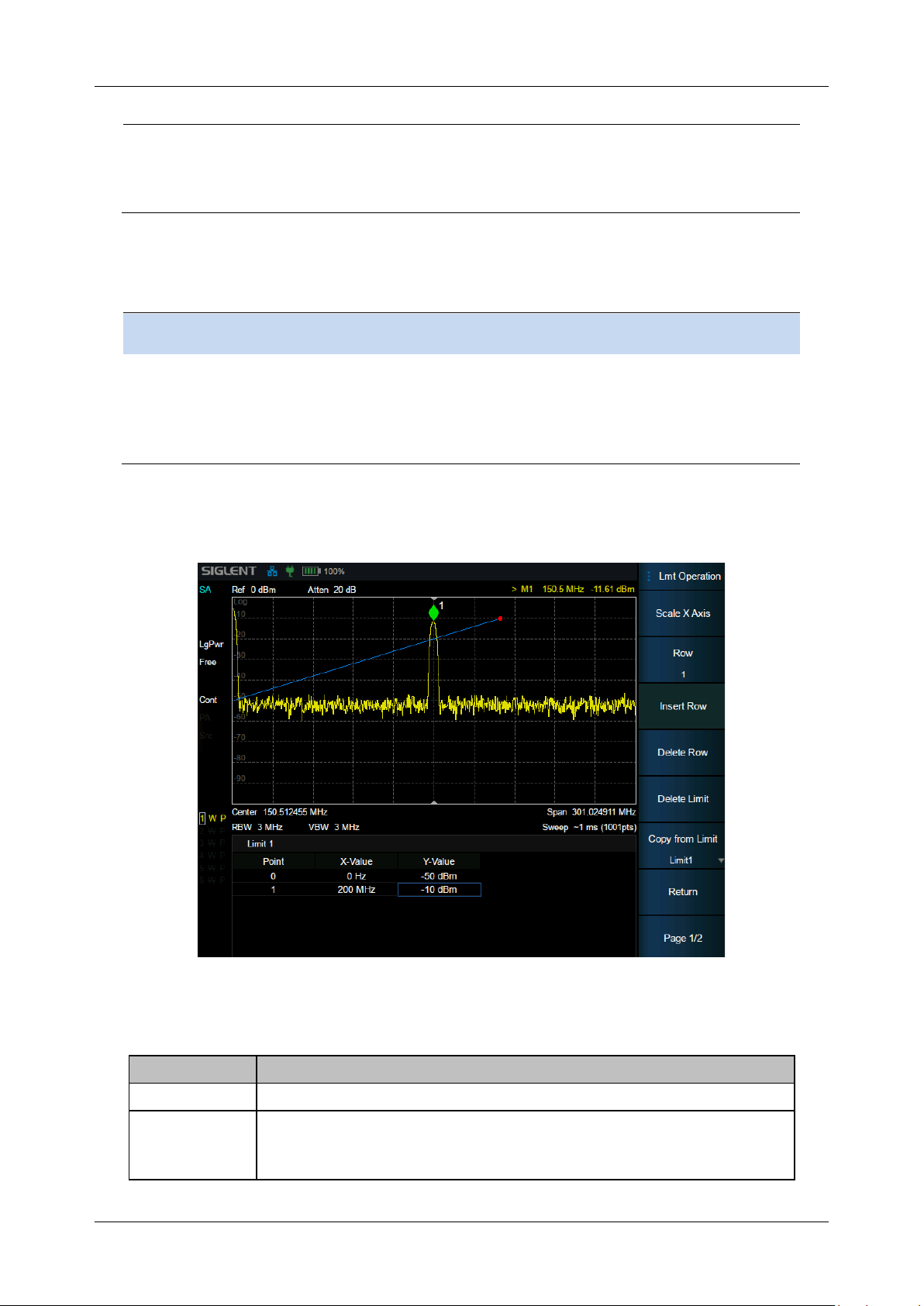
SHA850A User Manual
www.siglent.com 63
Parameter Type
Boolean
Parameter Range
OFF|ON|0|1
Return
0|1
Example
:CALCulate:LLINe1:MARGin:STATe OFF
3.8.3 Limit Type
Set the limit type as upper / lower. The limit 1,3,5 is default as the lower and 2,4,6 as the lower
Command format
:CALCulate:LLINe[1]|2|3|4|5|6:TYPE UPPer|LOWer
:CALCulate:LLINe[1]|2|3|4|5|6:TYPE?
Instructions
Sets/Gets the restriction type
Parameter Type
Enumeration
Parameter Range
UPPer|LOWer
Return
Enumeration
Example
:CALCulate:LLINe1:TYPE LOWer
3.8.4 Limit Edit
Edit the properties of selected limit.
Figure 3-4 limit edit
Table 3-1 Limit1 Edit Menu
Function
Explanation
Type
Select upper or lower limit type. The default value is Upper.
Mode
Select limit line or limit point. The default value is Line.
Set the number of the point to be edited if you selected the point type,
and the range is 1 ~ 100.
Page 88

SHA850A User Manual
64 www.siglent.com
Add point
Add a new point for editing.
X-axis
Edit the X-axis value (frequency or time) of the current point.
Amplitude
Edit the amplitude of the current point or line.
Del Point
Delete the point whose number is selected in Mode.
Del All
Delete all the points.
Save/Load
Save or load the limit file.
X Offset
Set offsets of X axis.
Y Offset
Set offsets of Y axis
Command format
:CALCulate:LLINe[1]|2|3|4|5|6:Offset:X
:CALCulate:LLINe[1]|2|3|4|5|6:Offset:X?
Instructions
Set the limit point template frequency offset
Gets the limit point template frequency offset
Parameter Type
Float
Parameter Range
0 ~ 26.5G
Return
Float
Example
:CALCulate:LLINe[1]|2|3|4|5|6:Offset:X 1MHz
Command format
:CALCulate:LLINe[1]|2|3|4|5|6:Offset:Y
:CALCulate:LLINe[1]|2|3|4|5|6:Offset:Y?
Instructions
Sets the limit point template amplitude offset
Gets the limiter template amplitude offset
Parameter Type
Float
Parameter Range
-350 dB~380 dB
Return
Float
Example
:CALCulate:LLINe5:Offset:Y -10
Command format
:CALCulate:LLINe[1]|2|3|4|5|6:DATA val1,val2
:CALCulate:LLINe[1]|2|3|4|5|6:DATA?
Instructions
Sets/gets restricted data
(Clears previous data)
Parameter Type
val1 : frequency : Float,
val2 : Ampl : Float
Parameter Range
val1 : related with Span
val2 : -400 dBm~330 dBm
Return
val1 : frequency : Float,
val2 : Ampl : Float
Example
:CALCulate:LLINe2:DATA 100,-20,200,-25 (add two points (100 , -20) and
(200 , -25 ) )
:CALC:LLINe1:DATA?
Command format
:CALCulate:LLINe[1]|2|3|4|5|6:ADD val1,val2
:CALCulate:LLINe[1]|2|3|4|5|6:POINt:DELete
Instructions
Add limit point
Delete limit points
Parameter Type
val1 : frequency : Float,
Page 89
SHA850A User Manual
www.siglent.com 65
val2 : Ampl : Float
Parameter Range
val1 : related with Span
val2 : -400 dBm~330 dBm
Example
:CALCulate:LLINe1:ADD 100,-20
:CALCulate:LLINe2:POINt:DELete 2
Command format
:CALCulate:LLINe[1]|2|3|4|5|6:DELete
:CALCulate:LLINe:ALL:DELete
Instructions
Delete specified restrictions
Delete all restrictions
Example
:CALCulate:LLINe1:DELete
:CALCulate:LLINe:ALL:DELete
Command format
:CALCulate:LLINe[1]|2|3|4|5|6:TRACe
:CALCulate:LLINe[1]|2|3|4|5|6:TRACe?
Instructions
Select the limit trace
Parameter Type
Integer
Parameter Range
1~6
Return
1~6
Example
:CALCulate:LLINe1:TRACe 3
Command format
:CALCulate:LLINe[1]|2|3|4|5|6:FREQuency:INTerpolate:TYPE
:CALCulate:LLINe[1]|2|3|4|5|6:FREQuency:INTerpolate:TYPE?
Instructions
Set/Query the frequency difference type
Parameter Type
Enumeration
Parameter Range
LOG|LIN
Return
LOG|LIN
Example
:CALCulate:LLINe1:FREQuency:INTerpolate:TYPE LOG
Command format
:CALCulate:LLINe[1]|2|3|4|5|6:FREQuency:CMODe
:CALCulate:LLINe[1]|2|3|4|5|6:FREQuency:CMODe?
Instructions
Set or query the frequency reference type
Parameter Type
Enumeration
Parameter Range
FIXed|RELAtive
Return
FIXed|RELAtive
Example
:CALCulate:LLINe2:FREQuency:CMODe FIX
Command format
:CALCulate:LLINe[1]|2|3|4|5|6:AMPLitude:INTerpolate:TYPE
:CALCulate:LLINe[1]|2|3|4|5|6:AMPLitude:INTerpolate:TYPE?
Instructions
Set or query the range difference type
Parameter Type
Enumeration
Parameter Range
LOG|LIN
Return
LOG|LIN
Example
:CALCulate:LLINe1: AMPLitude:INTerpolate:TYPE LOG
Command format
:CALCulate:LLINe[1]|2|3|4|5|6: AMPLitude:CMODe
:CALCulate:LLINe[1]|2|3|4|5|6: AMPLitude:CMODe?
Page 90
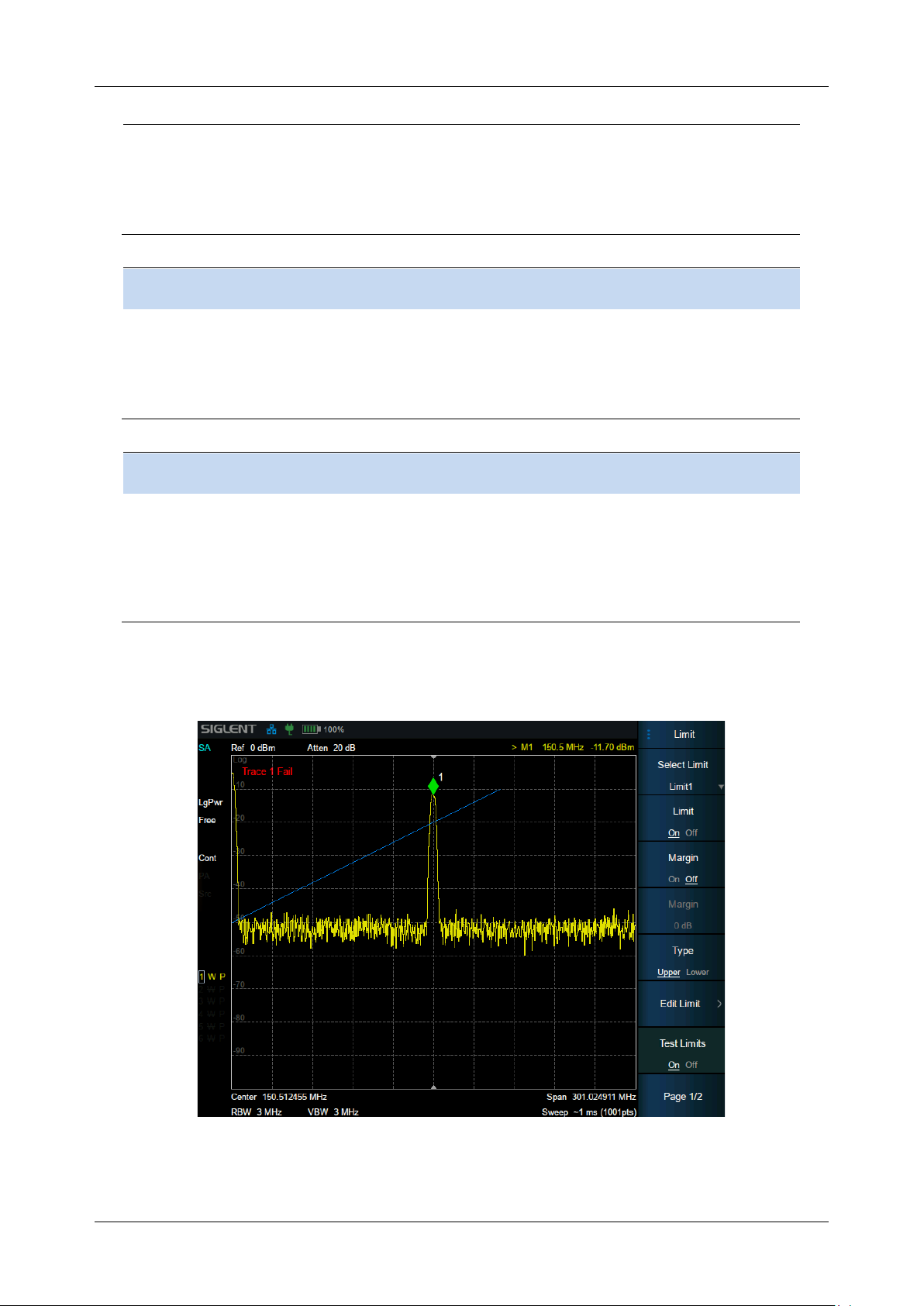
SHA850A User Manual
66 www.siglent.com
Instructions
Set or query the amplitude reference type
Parameter Type
Enumeration
Parameter Range
FIXed|RELAtive
Return
FIXed|RELAtive
Example
:CALCulate:LLINe2: AMPLitude:CMODe FIX
Command format
:CALCulate:LLINe[1]|2|3|4|5|6:COPY
:CALCulate:LLINe[1]|2|3|4|5|6:COPY?
Instructions
Copy the limit
Parameter Type
Integer
Parameter Range
1~6
Return
1~6
Example
:CALCulate:LLINe2:COPY 5
Command format
:CALCulate:LLINe[1]|2|3|4|5|6:BUILd
:CALCulate:LLINe[1]|2|3|4|5|6:BUILd?
Instructions
Fitting a trace
Parameter Type
Integer
Parameter Range
1~6
Return
1~6
Example
:CALCulate:LLINe2: BUILd 1
:CALCulate:LLINe2: BUILd?
3.8.5 Limit Test
Enable or disable the limit test function.
Figure 3-5 test results
Page 91

SHA850A User Manual
www.siglent.com 67
Command format
:CALCulate:LLINe:TEST
:CALCulate:LLINe:TEST?
Instructions
Sets/gets the status of the test switch
Parameter Type
Boolean
Parameter Range
OFF|ON|0|1
Return
0|1
Example
:CALCulate:LLINe:TEST 1
Command format
:CALCulate:LLINe[1]|2|3|4|5|6:FAIL?
Instructions
Query limit test results.
Return
0|1
Example
:CALCulate:LLINe2:FAIL 1
3.8.6 Setup
Fail to stop
Turn on or off the Fail to stop function. If the function is on, the analyzer will stop sweep and retain the
test result when the test result is “Fail”.
Buzzer
Turn on or off the buzzer. When the buzzer is on, it beeps when the test result is “Fail”.
Command format
:CALCulate:LLINe:CONTrol:BEEP
:CALCulate:LLINe:CONTrol:BEEP?
Instructions
Sets/gets the restricted buzzer
Parameter Type
Boolean
Parameter Range
OFF|ON|0|1
Return
0|1
Example
:CALCulate:LLINe:CONTrol:BEEP OFF
Command format
:CALCulate:LLINe:FAIL:STOP
:CALCulate:LLINe:FAIL:STOP?
Instructions
The set/query limit test stops if it fails
Parameter Type
Boolean
Parameter Range
OFF|ON|0|1
Return
0|1
Example
:CALCulate:LLINe:FAIL:STOP OFF
3.9 Meas & Meas Setup
Provide optional measurement functions. When activated, the screen will be divided into two parts.
The above part is the measure screen which displays traces, and the other part is used to display
measurement results.
Page 92
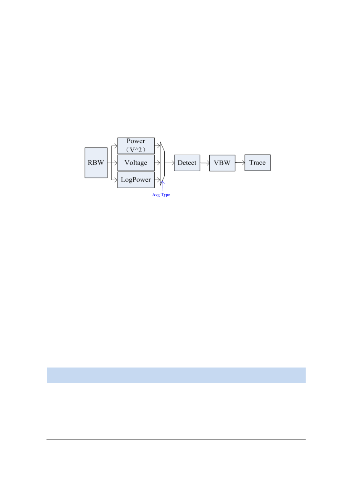
SHA850A User Manual
68 www.siglent.com
3.9.1 Swept SA
The Swept SA measurement lets you perform “traditional” Spectrum Analysis, that is, Swept and Zero
Span measurements, as well as “Swept FFT” analysis (FFT analysis presented as though it were
swept).
3.9.1.1 Average Type
Choose one of the following averaging types: log power (video), power (RMS), or voltage averaging.
When trace average is on, the average type is shown on the left side of the display.
Figure 3-6 Average Type
⚫ Log Power
Select the logarithmic (decibel) scale for all filtering and averaging processes. This scale is
"Video" because it is the most common display and analysis scale for the video signal within
analyzer. This scale is excellent for finding Sine/CW signals near noise.
⚫ Power Average
In this average type, all filtering and averaging processes work on the power (the square of the
magnitude) of the signal, instead of its log or envelope voltage. This scale is best for real-time
power measurement of complex signals.
⚫ Voltage Average
In this Average type, all filtering and averaging processes work on the voltage of the envelope of
the signal. This scale is suitable for observing rise and fall behavior of AM or pulse-modulated
signals such as radar and TDMA transmitters.
Command format
[:SENSe]:AVERage:TYPE LOGPower|POWer|VOLTage
[:SENSe]:AVERage:TYPE?
Instructions
Set/Query the average type
Parameter type
Enumeration
Parameter Range
LOGPower
POWer
VOLTage
Return
Enumeration : LOGP|POW|VOLT
Example
AVERage:TYPE VOLTage
Page 93

SHA850A User Manual
www.siglent.com 69
Command format
[:SENSe]:AVERage:TYPE:AUTO 0|1|ON|OFF
[:SENSe]:AVERage:TYPE:AUTO?
Instructions
Set/query the average type automatically
Parameter type
Boolean
Parameter Range
OFF|ON|0|1
Return
0|1
Example
:AVERage:TYPE:AUTO 1
3.9.1.2 Average/Hold Number
Sets the terminal count number N for Average, Max Hold and Min Hold trace types.This number is an
integral part of how the average trace is calculated. Basically,increasing N results in a smoother
average trace.
Command format
[:SENSe]:AVERage:TRACe[1]|2|3|4|5|6:COUNt
[:SENSe]:AVERage:TRACe[1]|2|3|4|5|6:COUNt?
Instructions
Sets/gets the average number of traces
Parameter type
Integer
Parameter Range
1 ~ 999
Return
Integer
Example
:AVERage:TRACe1:COUNt 10
Command format
[:SENSe]:AVERage:TRACe[1]|2|3|4|5|6?
[:SENSe]:AVERage:TRACe[1]|2|3|4|5|6:CLEar
Instructions
The current average number of times the trace has been obtained
Restart average
Example
:AVERage:TRACe2 ?
:AVERage:TRACe2:CLEar
3.9.1.3 Tune & Radio
⚫ Demod(AM/FM)
Sets the demodulation type of AM,FM or OFF demod. Default setting is OFF demod.
When AM(or FM) demodulation is turned on, the system automatically opens a cursor to position
it at the center frequency, and perform AM (or FM) demodulation for this frequency point.
This machine is equipped with a headphone jack, through which demodulation signal can be
output in audio mode. Audio frequency represents the frequency of the modulated signal, and the
intensity of audio indicates the amplitude of the modulated signal.
⚫ Earphone
Set the headset status/volume.When the headset is turned on, the voice of the modulation signal
can be heard through the headset during the demodulation process. The headset is disabled by
default.You can set the volume of the headset by volume.
⚫ Demodulation time
Page 94

SHA850A User Manual
70 www.siglent.com
Set the dwell time of signal demodulation after each sweep. Longer dwell time will benefit
continuous demodulation signal.
If the headset is turned on, the voice of the demodulated signal will be heard through the headset
during this period.
Command format
[:SENSe]:DEMod AM|FM|OFF
[:SENSe]:DEMod?
Instructions
Sets the demodulation mode
Gets the demodulation mode
Parameter type
Enumeration
Parameter Range
AM : Amplitude modulation
FM : Frequency modulation
OFF
Return
Enumeration: AM|FM|OFF
Example
:DEMod AM
Command format
[:SENSe]:DEMod:EPHone OFF|ON|0|1
[:SENSe]:DEMod:EPHone?
Instructions
Switch the headset
Parameter type
Boolean
Parameter Range
OFF|ON|0|1
Return
0|1
Example
:DEMod:EPHone ON
Command format
[:SENSe]:DEMod:VOLume
[:SENSe]:DEMod:VOLume?
Instructions
Adjust the volume
Parameter type
Integer
Parameter Range
0 ~ 10
Return
Integer
Example
:DEMod:VOLume 10
Command format
[:SENSe]:DEMod:TIME
[:SENSe]:DEMod:TIME?
Instructions
Set the demodulation time
Get demodulation time
Parameter type
Float , unitms , us , s
Parameter Range
5 ms ~1000 s
Return
Float , units
Example
DEMod:TIME 5 ms
3.9.1.4 Automatic coupling
Auto coupling instantly sets all auto/manual functions to auto. The automatic coupling action is limited
to the current measurement. It does not affect other measurements in the mode.
In the automatic state, the automatic/manual functions are referred to as "coupled", which means that
Page 95

SHA850A User Manual
www.siglent.com 71
their values will change based on changes made to other values in the measurement. This helps
ensure accurate measurements and optimal dynamic range. Automatic coupling is a just-in-time
action feature that, when it is performed, all automatic/manual controls for the current measurement
are set to automatic and all measurement settings coupled to automatic/manual parameters are
automatically set to their best values.
Command format
:COUPle:ALL
Instructions
Automatic coupling
Example
:COUPle:ALL
3.9.1.5 Display line
The amplitude line can be used as a reference for the amplitude readout or as a threshold condition
for the peak display in the peak table.
The frequency line can be used as a reference for frequency readout.
Command format
:DISPlay:WINDow:TRACe:Y:DLINe
:DISPlay:WINDow:TRACe:Y:DLINe?
Instructions
Sets/gets the amplitude display line
Parameter type
Float
Return
Float
Example
:DISPlay:WINDow:TRACe:Y:DLINe -40
Command format
:DISPlay:WINDow:TRACe:Y:DLINe:STATe
:DISPlay:WINDow:TRACe:Y:DLINe:STATe?
Instructions
Set/get amplitude display line automatically
Parameter type
Boolean
Parameter Range
OFF|ON|0|1
Return
0|1
Example
:DISPlay:WINDow:TRACe:Y:DLINe:STATe 1
Command format
:DISPlay:WINDow:TRACe:X:FLINe
:DISPlay:WINDow:TRACe:X:FLINe?
Instructions
Set/Obtain the frequency display line
Parameter type
Float
Return
Float
Example
:DISPlay:WINDow:TRACe:X:FLINe 100e6
Command format
:DISPlay:WINDow:TRACe:X:FLINe:STATe
:DISPlay:WINDow:TRACe:X:FLINe:STATe?
Instructions
Set/get frequency display line automatically
Parameter type
Boolean
Parameter Range
OFF|ON|0|1
Return
0|1
Example
:DISPlay:WINDow:TRACe:X:FLINe:STATe 1
Page 96

SHA850A User Manual
72 www.siglent.com
3.9.1.6 Gloabl
The global center frequency causes the current center frequency to act on other measurements /
swep.
Command format
:INSTrument:COUPle:FREQuency:CENTer
:INSTrument:COUPle:FREQuency:CENTer?
Instructions
Enable/disable the global center frequency
Parameter Type
Boolean
Parameter Range
ON|OFF|0|1
Return
0|1
Example
:INSTrument:COUPle:FREQuency:CENTer 0
:INSTrument:COUPle:FREQuency:CENTer?
3.9.1.7 Source
There are two Source type:
CW:
CW Freq: Set the Independent source frequency, which synchronizes the SA receiver's center
frequency setting, so the signal is displayed in the center of the screen;
CW Level: Enter a number from -40 dBm to 0 dBm. The source power is displayed flat over the
frequency range.
CW offset:
Offset to CF : The distance the signal is offset by IF;
CW Offset Level : Signal peak amplitude offset.
Command format
[:SENSe]:SOURce:STATe 0|1|ON|OFF
[:SENSe]:SOURce:STATe?
Instructions
Parameter type
Parameter Range
Return
Set/Query the source state
Boolean
OFF|ON|0|1
0|1
Example
:SOURce:STATe 0
:SOURce:STATe ?
Command format
[:SENSe] :SOURce:TYPE CW
[:SENSe] :SOURce:TYPE?
Instructions
Parameter type
Parameter Range
Return
Set/Query the source type
Enumeration
CW|CWC
Enumeration CW|CWC
Example
:SOURce:TYPE CW
:SOURce:TYPE?
Page 97

SHA850A User Manual
www.siglent.com 73
Command format
[:SENSe]:SOURce:CW:FREQuency
[:SENSe]:SOURce:CW:FREQuency?
Instructions
Sets the CW FREQ
Gets the CW FREQ
Parameter Type
Float
Parameter Range
100KHz~7.5GHz
Return
Float
Example
:SOURce:CW:FREQuency 10MHz
:SOURce:CW:FREQuency?
Command format
[:SENSe]:SOURce:CW:POWer
[:SENSe]:SOURce:CW:POWer?
Instructions
Sets the CW POWer
Gets the CW POWer
Parameter Type
Float
Parameter Range
-40 dB~0 dB
Return
Float
Example
:SOURce:CW:POWer -10
:SOURce:CW:POWer?
Command format
[:SENSe]:SOURce:CWCoupled:FREQuency:OFFSet
[:SENSe]:SOURce:CWCoupled:FREQuency:OFFSet?
Instructions
Sets the offset to CF
Gets the offset to CF
Parameter Type
Float
Parameter Range
-100GHz~100GHz
Return
Float
Example
:SOURce:CWCoupled:FREQuency:OFFSet -10
:SOURce:CWCoupled:FREQuency:OFFSet?
Command format
[:SENSe]:SOURce:CWCoupled:POWer
[:SENSe]:SOURce:CWCoupled:POWer?
Instructions
Sets the CW Offset POWer
Gets the CW Offset POWer
Parameter Type
Float
Parameter Range
-40 dB~0 dB
Return
Float
Example
:SOURce:CWCoupled:POWer -10
:SOURce:CWCoupled:POWer?
3.9.2 Channel Power
Measure the power and power density within the specified channel bandwidth. When this function is
enabled, the span and resolution bandwidth are automatically adjusted to smaller values. Select
Channel Power and press Meas Setup to set the corresponding parameters.
Page 98
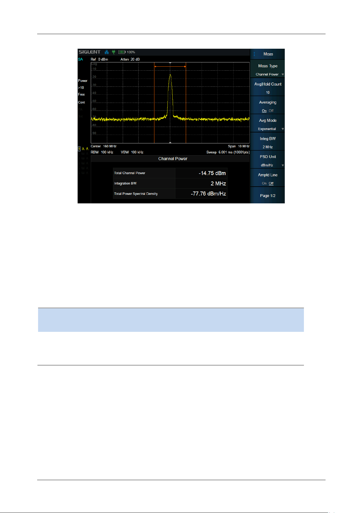
SHA850A User Manual
74 www.siglent.com
Figure 3-7 Channel Power
Measurement Results: Channel power and power spectral density.
⚫ Channel Power: Power within the integration bandwidth.
⚫ Power Spectral Density: Power (in dBm/Hz) normalized to 1Hz within the integration bandwidth.
Measurement Parameters: Center Freq, Integration BW, Span, Span power.
Command format
:CHPower:MEASure:CHPower?
:CHPower:MEASure:CHPower:CHPower?
:CHPower:MEASure:CHPower:DENSity?
Instructions
Read channel power and power spectral density
Return
Float , Channel power unit: dBm
Float , A unit of spectral density of power :dBm/Hz
Example
:CHPower:MEASure:CHPower?
3.9.2.1 Average Mode
Select the type of control used for the averaging function. This determines the average operation after
the specified number of data acquisitions (average count) has been reached. Options include:
Exponentialr :
The measure average operation continuously calculates a weighted average for each index using a
specified number of averages.
Repeat :
Page 99

SHA850A User Manual
www.siglent.com 75
Each time the specified average is reached, the measurement resets the average counter.
Command format
[:SENSe]:CHPower:AVERage:TCONtrol
[:SENSe]:CHPower:AVERage:TCONtrol?
Instructions
Sets/gets the average mode
Parameter type
Enumeration
Parameter Range
EXPOnentialr|REPEat
Return
EnumerationEXPOnentialr|REPEat
Example
:CHPower:AVERage:TCONtrol REPEat
3.9.2.2 Integration BW
Set the frequency width of the channel to be tested and the power of the channel is the power integral
within this bandwidth. You can use the numeric keys, knob or direction keys to modify this parameter.
Command format
[:SENSe]:CHPower:BWIDth:INTegration
[:SENSe]:CHPower:BWIDth:INTegration?
Instructions
Sets/gets the integral bandwidth
Parameter type
Float , unitHz , kHz , MHz , GHz
Return
Float m unitHz
Example
:CHPower:BWIDth:INTegration 1.0 GHz
Command format
[:SENSe]:CHPower:FREQuency:SPAN:POWer
Instructions
Sets the value of channel sweep to the integral bandwidth
Example
:CHPower:FREQuency:SPAN:POWer
3.9.2.3 PSD Unit
Select power spectral density unit, optional dBm/Hz , dBm/MHz.
Command format
:UNIT:CHPower:POWer:PSD
:UNIT:CHPower:POWer:PSD?
Instructions
Select the power spectral density unit
Parameter type
Enumeration
Parameter Range
DBMHZ|DBMMHZ
Return
DBMHZ|DBMMHZ
Example
:UNIT:CHPower:POWer:PSD DBMHZ
:UNIT:CHPower:POWer:PSD?
3.9.3 ACPR
Measure the power of the main channel and adjacent channels as well as the power difference
between the main channel and each of the adjacent channels. When this function is enabled, the span
and resolution bandwidth of the analyzer are adjusted to smaller values automatically.
Select ACPR and press Meas Setup to set the corresponding parameters.
Page 100
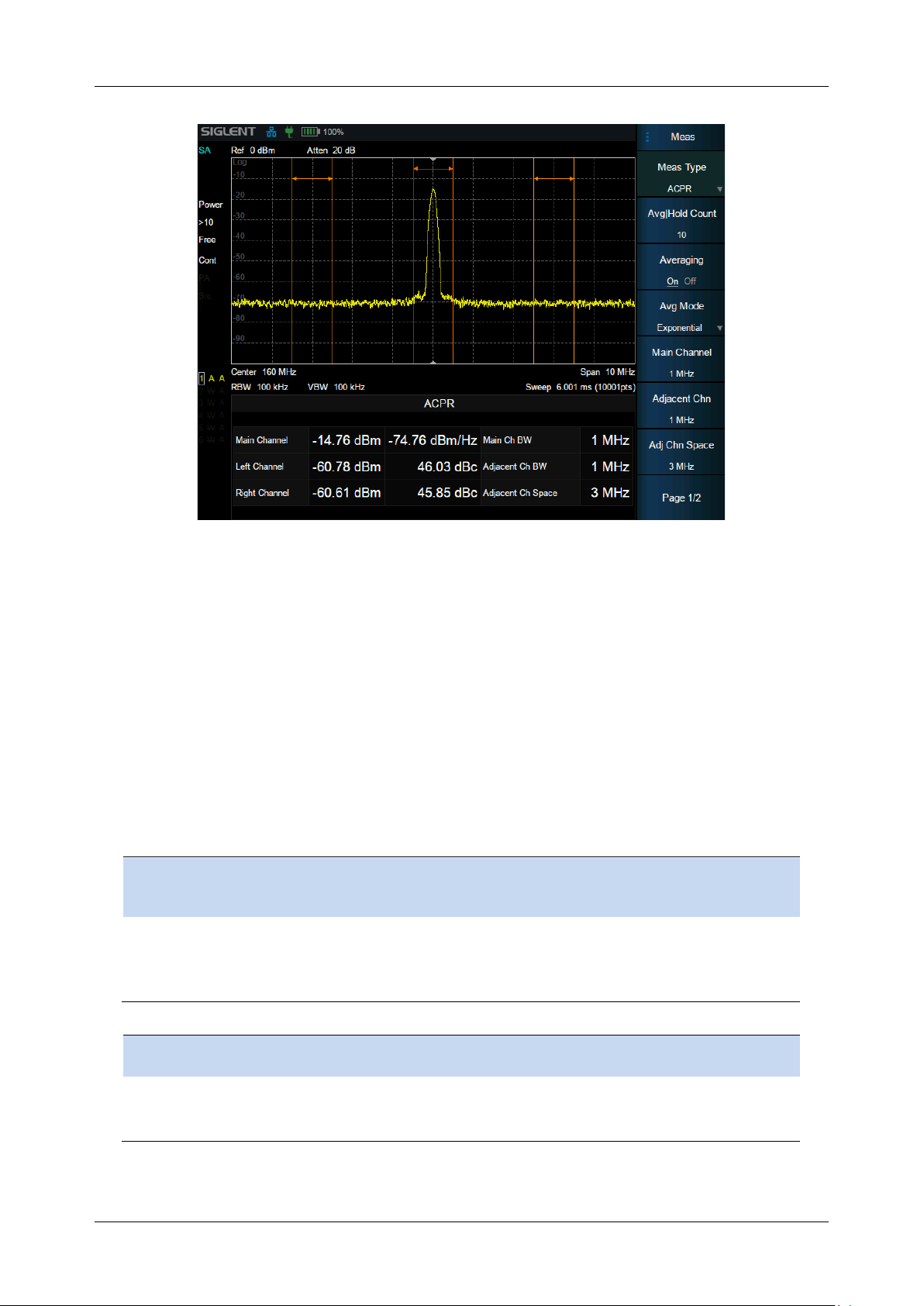
SHA850A User Manual
76 www.siglent.com
Figure 3-8 ACPR
Measurement Results: Main CH Power, Left channel power and Right channel power.
⚫ Main CH Power: Displays the power within the bandwidth of the main power
⚫ Left channel power : Displays the power of left channel and the power difference between
the left channel and the main channel (in dBc)
⚫ Right channel power: Display the power of the right channel and the power difference
between the right channel and the main channel(in dBc)
Measurement parameter: Center frequency, main channel bandwidth, adjacent channel bandwidth
and channel spacing
Command format
:MEASure:ACPRatio:ACPower:MAIN?
:MEASure:ACPRatio:LOWer:POWer?
:MEASure:ACPRatio:UPPer:POWer?
Instructions
Get the main channel power
Obtain low and high frequency adjacent channel power
Return
Float , unitdBm
Example
:MEASure:ACPRatio:ACPower:MAIN?
Command format
:MEASure:ACPRatio:LOWer?
:MEASure:ACPRatio:UPPer?
Instructions
Obtain the low frequency/high frequency adjacent channel power ratio
Return
Float , unitdBm
Example
:MEASure:ACPRatio:LOWer?
 Loading...