

SIGLENT SDS5000X Series User Manual
SDS5000X Series Digital Oscilloscope User Manual
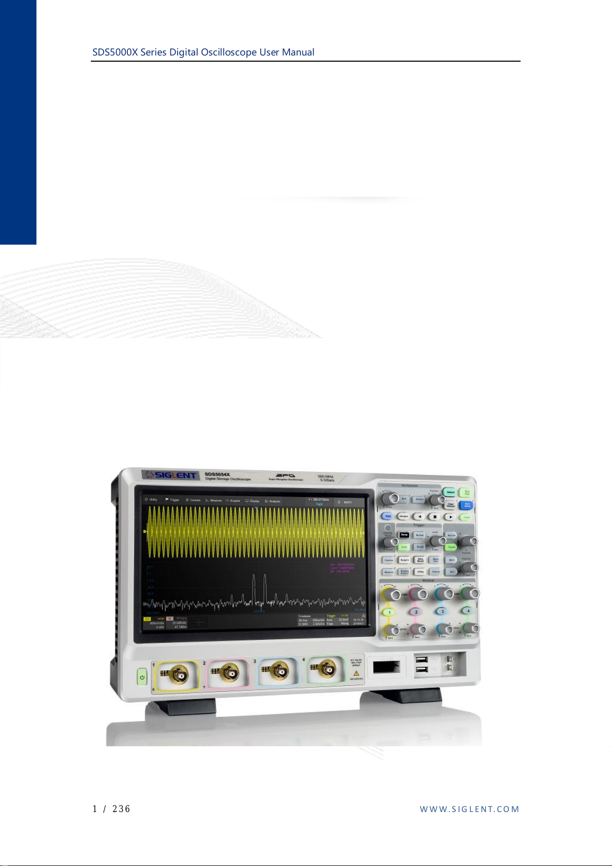
SDS5000X Series
Digital Oscilloscope
User Manual
UM0105X-E01A
1 / 236 W W W . S IG L E N T. C O M

SDS5000X Series Digital Oscilloscope User Manual
Contents
CONTENTS ............................................................................................................................................................................ 2
1 INTRODUCTION ................................................................................................................................................... 6
2 GENERAL SAFETY SUMMARY ....................................................................................................................... 7
2.1 SAFETY TERMS AND SYMBOLS ........................................................................................................................... 7
2.2 WORKING ENVIRONMENT................................................................................................................................... 8
2.3 COOLING REQUIREMENTS................................................................................................................................... 9
2.4 AC POWER ........................................................................................................................................................ 10
2.5 POWER AND GROUND CONNECTIONS ................................................................................................................ 11
2.6 CALIBRATION .................................................................................................................................................... 12
2.7 CLEANING ......................................................................................................................................................... 12
2.8 ABNORMAL CONDITIONS .................................................................................................................................. 12
3 FIRST STEPS......................................................................................................................................................... 14
3.1 DELIVERY CHECKLIST ...................................................................................................................................... 14
3.2 QUALITY ASSURANCE ...................................................................................................................................... 14
3.3 MAINTENANCE AGREEMENT ............................................................................................................................ 15
4 DOCUMENT CONVENTIONS .......................................................................................................................... 16
5 GETTING STARTED .......................................................................................................................................... 17
5.1 POWER ON ......................................................................................................................................................... 17
5.2 SHUT DOWN ...................................................................................................................................................... 17
5.3 SYSTEM STATUS ............................................................................................................................................... 18
5.4 INSTALL OPTIONS ............................................................................................................................................. 18
6 PROBE .................................................................................................................................................................... 19
7 QUICK START...................................................................................................................................................... 21
7.1 FRONT PANEL OVERVIEW................................................................................................................................. 21
7.2 REAR PANEL OVERVIEW .................................................................................................................................. 22
7.3 CONNECTING TO EXTERNAL DEVICES/SYSTEMS.............................................................................................. 24
7.3.1 Power Supply........................................................................................................................................... 24
7.3.2 LAN .......................................................................................................................................................... 24
7.3.3 USB Peripherals...................................................................................................................................... 24
7.3.4 External Monitor ..................................................................................................................................... 24
7.3.5 Auxiliary Output ...................................................................................................................................... 25
7.3.6 SAG1021 Waveform Generator ............................................................................................................. 25
7.3.7 Probes ...................................................................................................................................................... 25
7.3.8 Logic Probe ............................................................................................................................................. 26
8 TOUCH SCREEN DISPLAY .............................................................................................................................. 27
8.1 OVERVIEW ........................................................................................................................................................ 27
8.2 MENU BAR ........................................................................................................................................................ 28
8.3 GRID AREA ....................................................................................................................................................... 29
8.4 CHANNEL DESCRIPTOR BOX............................................................................................................................. 30
8.5 TIMEBASE AND TRIGGER DESCRIPTOR BOXES ................................................................................................. 32
8.6 DIALOG BOX ..................................................................................................................................................... 35
8.7 TOUCH GESTURES............................................................................................................................................. 37
8.8 MOUSE AND KEYBOARD OPERATION ............................................................................................................... 39
8.9 CHOOSING THE LANGUAGE .............................................................................................................................. 39
9 FRONT PANEL ..................................................................................................................................................... 40
9.1 OVERVIEW ........................................................................................................................................................ 40
9.2 VERTICAL CONTROL ......................................................................................................................................... 41
9.3 HORIZONTAL CONTROL .................................................................................................................................... 42
9.4 TRIGGER CONTROL ........................................................................................................................................... 43
9.5 RUN/STOP BUTTON .......................................................................................................................................... 43
9.6 AUTOSETUP BUTTON ....................................................................................................................................... 44
9.7 DECODE/DIGITAL/MATH/REF CONTROL.......................................................................................................... 44
9.8 NAVIGATE CONTROL ........................................................................................................................................ 45
9.9 CURSORS CONTROL .......................................................................................................................................... 46
2 / 236 W W W . S IG L E N T. C O M

SDS5000X Series Digital Oscilloscope User Manual
9.10 UNIVERSAL KNOB............................................................................................................................................. 46
9.11 OTHER BUTTONS .............................................................................................................................................. 47
10 MULTIPLE APPROACHES TO RECALL FUNCTIONS ....................................................................... 48
10.1 MENU BAR ........................................................................................................................................................ 48
10.2 DESCRIPTOR BOX.............................................................................................................................................. 49
10.3 SHORTCUT BUTTON ON THE FRONT PANEL ...................................................................................................... 49
11 QUICKLY CAPTURE THE SIGNAL .......................................................................................................... 50
12 VERTICAL SETUP .......................................................................................................................................... 51
12.1 TURN ON/OFF A CHANNEL ................................................................................................................................ 51
12.2 CHANNEL SETUP ............................................................................................................................................... 51
13 DIGITAL CHANNELS .................................................................................................................................... 57
13.1 OVERVIEW ........................................................................................................................................................ 57
13.2 ENABLE/DISABLE THE DIGITAL CHANNELS ..................................................................................................... 59
13.3 DIGITAL CHANNEL SETUP ................................................................................................................................ 60
14 HORIZONTAL AND ACQUISITION SETUP............................................................................................ 64
14.1 TIMEBASE SETUP .............................................................................................................................................. 64
14.2 ACQUISITION SETUP ......................................................................................................................................... 65
14.2.1 Overview .................................................................................................................................................. 65
14.2.2 Acquisition ............................................................................................................................................... 67
14.2.3 Roll Mode ................................................................................................................................................ 71
14.2.4 Sequence .................................................................................................................................................. 71
14.3 HISTORY............................................................................................................................................................ 75
14.4 ZOOM ................................................................................................................................................................ 78
15 TRIGGER ........................................................................................................................................................... 80
15.1 OVERVIEW ........................................................................................................................................................ 80
15.2 TRIGGER SETUP ................................................................................................................................................ 81
15.3 TRIGGER LEVEL ................................................................................................................................................ 83
15.4 TRIGGER MODE ................................................................................................................................................ 84
15.5 TRIGGER TYPE .................................................................................................................................................. 85
15.5.1 Overview .................................................................................................................................................. 85
15.5.2 Edge Trigger............................................................................................................................................ 86
15.5.3 Slope Trigger ........................................................................................................................................... 86
15.5.4 Pulse Trigger ........................................................................................................................................... 89
15.5.5 Video Trigger .......................................................................................................................................... 90
15.5.6 Window Trigger ...................................................................................................................................... 95
15.5.7 Interval Trigger ....................................................................................................................................... 97
15.5.8 Dropout Trigger ...................................................................................................................................... 97
15.5.9 Runt Trigger ............................................................................................................................................ 99
15.5.10 Pattern Trigger...................................................................................................................................... 100
15.5.11 Qualified Trigger .................................................................................................................................. 101
15.6 TRIGGER SOURCE............................................................................................................................................ 103
15.7 HOLDOFF......................................................................................................................................................... 104
15.8 TRIGGER COUPLING ........................................................................................................................................ 106
15.9 NOISE REJECT ................................................................................................................................................. 106
16 SERIAL TRIGGER AND DECODE ........................................................................................................... 108
16.1 OVERVIEW ...................................................................................................................................................... 108
16.2 I2C TRIGGER AND SERIAL DECODE ............................................................................................................... 110
16.2.1 I2C Signal Settings ................................................................................................................................ 110
16.2.2 I2C Trigger ............................................................................................................................................ 111
16.2.3 I2C Serial Decode ................................................................................................................................. 116
16.3 SPI TRIGGER AND SERIAL DECODE ................................................................................................................ 119
16.3.1 SPI Signal Settings ................................................................................................................................ 119
16.3.2 SPI Trigger ............................................................................................................................................ 121
16.3.3 SPI Serial Decode ................................................................................................................................. 121
16.4 UART TRIGGER AND SERIAL DECODE .......................................................................................................... 122
16.4.1 UART Signal Settings............................................................................................................................ 122
16.4.2 UART Trigger ........................................................................................................................................ 123
16.4.3 UART Serial Decode ............................................................................................................................. 124
16.5 CAN TRIGGER AND SERIAL DECODE ............................................................................................................. 125
3 / 236 W W W . S IG L E N T. C O M

SDS5000X Series Digital Oscilloscope User Manual
16.5.1 CAN Signal Settings .............................................................................................................................. 125
16.5.2 CAN Trigger .......................................................................................................................................... 126
16.5.3 CAN Serial Decode ............................................................................................................................... 126
16.6 LIN TRIGGER AND SERIAL DECODE ............................................................................................................... 128
16.6.1 LIN Signal Settings................................................................................................................................ 128
16.6.2 LIN Trigger............................................................................................................................................ 129
16.6.3 LIN Serial Decode ................................................................................................................................. 129
17 CURSORS......................................................................................................................................................... 131
17.1 OVERVIEW ...................................................................................................................................................... 131
17.2 SELECT AND MOVE CURSORS......................................................................................................................... 136
18 MEASUREMENT ........................................................................................................................................... 139
18.1 OVERVIEW ...................................................................................................................................................... 139
18.2 SET PARAMETERS ........................................................................................................................................... 141
18.3 TYPE OF MEASUREMENT ................................................................................................................................ 144
18.3.1 Vertical Measurement ........................................................................................................................... 144
18.3.2 Horizontal Measurement ...................................................................................................................... 146
18.3.3 Delay Measurement .............................................................................................................................. 147
18.4 MEASUREMENT STATISTICS ........................................................................................................................... 149
18.5 ALL MEASUREMENT ....................................................................................................................................... 150
18.6 GATE ............................................................................................................................................................... 150
19 MATH ............................................................................................................................................................... 152
19.1 OVERVIEW ...................................................................................................................................................... 152
19.2 ADDITION/SUBTRACTION/MULTIPLICATION/DIVISION .................................................................................. 154
19.3 DIFFERENTIAL ................................................................................................................................................. 154
19.4 INTEGRAL ........................................................................................................................................................ 156
19.5 SQUARE ROOT................................................................................................................................................. 158
19.6 FFT ................................................................................................................................................................. 159
20 REFERENCE ................................................................................................................................................... 166
21 SEARCH ........................................................................................................................................................... 168
22 NAVIGATE ...................................................................................................................................................... 171
23 PASS/FAIL ....................................................................................................................................................... 178
23.1 OVERVIEW ...................................................................................................................................................... 178
23.2 MASK SETUP ................................................................................................................................................... 180
23.2.1 Create Mask........................................................................................................................................... 181
23.2.2 Mask Editor ........................................................................................................................................... 182
23.3 PASS/FAIL RULE ............................................................................................................................................. 184
23.4 OPERATION ..................................................................................................................................................... 185
24 DISPLAY .......................................................................................................................................................... 186
25 ARBITRARY WAVEFORM GENERATOR............................................................................................. 193
25.1 OVERVIEW ...................................................................................................................................................... 193
25.2 OUTPUT ........................................................................................................................................................... 195
25.3 WAVE TYPE .................................................................................................................................................... 195
25.4 OTHER SETTING .............................................................................................................................................. 197
25.5 SYSTEM ........................................................................................................................................................... 199
26 SAVE/RECALL ............................................................................................................................................... 201
26.1 SAVE TYPE ...................................................................................................................................................... 201
26.2 INTERNAL SAVE AND RECALL ........................................................................................................................ 204
26.3 EXTERNAL SAVE AND RECALL ....................................................................................................................... 206
26.3.1
File manager ......................................................................................................................................... 206
26.3.2 External Save and Recall Instance....................................................................................................... 208
27 SYSTEM SETTING ........................................................................................................................................ 212
27.1 SYSTEM STATUS ............................................................................................................................................. 212
27.2 SOUND............................................................................................................................................................. 212
27.3 UPGRADE SOFTWARE ..................................................................................................................................... 213
27.4 LANGUAGE ...................................................................................................................................................... 215
27.5 SCREEN SAVER ............................................................................................................................................... 215
4 / 236 W W W . S IG L E N T. C O M

SDS5000X Series Digital Oscilloscope User Manual
27.6 I/O SETTING .................................................................................................................................................... 216
27.6.1 LAN ........................................................................................................................................................ 216
27.6.2 Clock Source.......................................................................................................................................... 217
27.7 DATE/TIME ..................................................................................................................................................... 217
27.8 INSTALL OPTIONS ........................................................................................................................................... 218
27.9 REFERENCE POSITION SETTING ...................................................................................................................... 220
27.10 PERFORM SELF TEST .................................................................................................................................. 223
27.11 DO SELF CAL .............................................................................................................................................. 226
27.12 POWER ON LINE .......................................................................................................................................... 227
27.13 DEBUG ........................................................................................................................................................ 227
28 REMOTE CONTROL .................................................................................................................................... 228
28.1 WEB BROWER ................................................................................................................................................. 228
28.2 OTHER CONNECTIVITY ................................................................................................................................... 230
29 TROUBLESHOOTING ................................................................................................................................. 231
30 CONTACT SIGLENT .................................................................................................................................... 234
5 / 236 W W W . S IG L E N T. C O M

SDS5000X Series Digital Oscilloscope User Manual
1 Introduction
This user manual includes important safety and installation information related
to the SDS5000X series oscilloscopes and includes simple tutorials for basic
operation of the oscilloscope.
6 / 236 W W W . S IG L E N T. C O M
SDS5000X Series Digital Oscilloscope User Manual
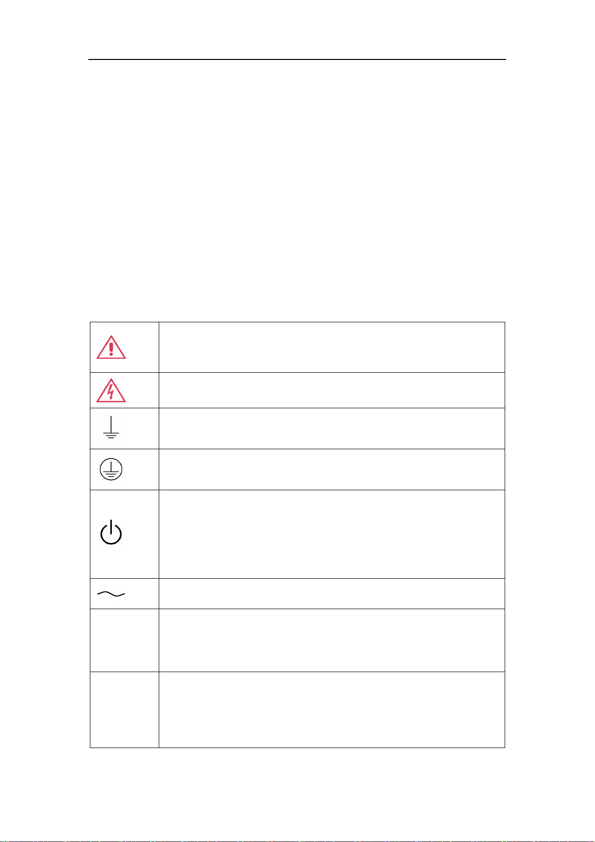
This symbol is used where caution is required. Refer to the
accompanying information or documents in order to protect against
personal injury or damage to the instrument.
This symbol warns of a potential risk of shock hazard.
This symbol is used to denote the measurement ground connection.
This symbol is used to denote a safety ground connection.
This symbol shows that the switch is an On/Standby switch. When it
is pressed, the scope’s state switches between Operation and
Standby. This switch does not disconnect the device's power supply.
To completely power off the scope, the power cord must be
unplugged from the AC socket after the oscilloscope is in the
standby state.
This symbol is used to represent alternating current, or "AC".
CAUTION
The "CAUTION" symbol indicates a potential hazard. It calls
attention to a procedure, practice or condition which may be
dangerous if not followed. Do not proceed until its conditions are fully
understood and met.
WARNING
The "WARNING" symbol indicates a potential hazard. It calls
attention to a procedure, practice or condition which, if not followed,
could possibly cause bodily injury or death. If a WARNING is
indicated, do not proceed until the safety conditions are fully
understood and met.
2 General Safety Summary
This chapter contains information and warnings that must be followed to keep
the instrument operating under the appropriate safety conditions. In addition to
the safety precautions specified in this section, you must also follow
recognized safety procedures.
2.1 Safety Terms and Symbols
When the following symbols or terms appear on the front or rear panel of the
instrument or in this manual, they indicate special care in terms of safety.
7 / 236 W W W . S IG L E N T. C O M
SDS5000X Series Digital Oscilloscope User Manual
WARNING: Do not operate the oscilloscope in an explosive
atmosphere or wet and damp conditions.
2.2 Working Environment
This instrument is intended for indoor use and should be operated in a clean,
dry environment with an ambient temperature range of 0 °C - 50 °C.
Note: Direct sunlight, radiators, and other heat sources should be taken into
account when assessing the ambient temperature.
The design of the instrument has been verified to conform to EN 61010-1
safety standard per the following limits:
Installation (overvoltage) Category: II (Mains Supply Connector) & I
(Measuring Terminals)
Degree of Pollution: II
Degree of Protection: I
Note:
Installation (Overvoltage) Category II refers to the local distribution level,
which is applicable to equipment connected to the mains supply (AC power
source).
Installation (Overvoltage) Category I refers to signal level, which is applicable
8 / 236 W W W . S IG L E N T. C O M
SDS5000X Series Digital Oscilloscope User Manual
CAUTION: Protect the display touch screen of the scope from
excessive impact.
CAUTION: Do not exceed the maximum specified front panel terminal
(CH1, CH2, CH3, CH4, EXT) voltage levels. Refer to Specifications for
more details.
CAUTION: Do not connect or disconnect probes or test leads while
they are connected to a voltage source.
to equipment measuring terminals that are connected to source circuits in
which measures are taken to limit transient voltages to an appropriately low
level.
Degree of Pollution II refers to a working environment which is dry and nonconductive pollution occurs. Occasional temporary conductivity caused by
condensation is expected.
Degree of Protection I refers to grounded equipment, in which protection
against electric shock is achieved by basic insulation and by means of a
connection to the protective ground conductor in the building wiring.
2.3 Cooling Requirements
This instrument relies on the forced air cooling with internal fans and
ventilation openings. Care must be taken to avoid restricting the airflow
around the apertures (fan holes) at each side of the scope. To ensure
adequate ventilation it is required to leave a 15 cm (6 inch) minimum gap
9 / 236 W W W . S IG L E N T. C O M

SDS5000X Series Digital Oscilloscope User Manual
CAUTION: Do not block the ventilation holes located on both sides of
the scope.
CAUTION: Do not allow any foreign matter to enter the scope through
the ventilation holes, etc.
Voltage Range:
90 - 264 Vrms
90 - 132 Vrms
Frequency Range:
47 - 63 Hz
380 - 420 Hz
around the sides of the instrument.
2.4 AC Power
The instrument operates with a single-phase, 100 to 240 Vrms (+/-10%) AC
power at 50/60 Hz (+/-5%), or single-phase 100 - 120 Vrms (+/-10%) AC
power at 400 Hz (+/-5%).
No manual voltage selection is required because the instrument automatically
adapts to line voltage.
Depending on the type and number of options and accessories (probes, PC
port plug-in, etc.), the instrument can consume up to 100 W of power.
Note: The instrument automatically adapts to the AC line input within the
following ranges:
10 / 236 W W W. S I G L E NT. CO M
SDS5000X Series Digital Oscilloscope User Manual
Warning: Electrical Shock Hazard!
Any interruption of the protective conductor inside or outside of the
scope, or disconnection of the safety ground terminal creates a
hazardous situation.
Intentional interruption is prohibited.
CAUTION: The outer shells of the front panel terminals (CH1, CH2,
CH3, CH4, EXT) are connected to the instrument’s chassis and
therefore to the safety ground.
2.5 Power and ground connections
The instrument includes a grounded cord set containing a molded threeterminal polarized plug and a standard IEC320 (Type C13) connector for
making line voltage and safety ground connection. The AC inlet ground
terminal is connected directly to the frame of the instrument. For adequate
protection against electrical shock hazard, the power cord plug must be
inserted into a mating AC outlet containing a safety ground contact. Use only
the power cord specified for this instrument and certified for the country of
use.
The position of the oscilloscope should allow easy access to the socket. To
make the oscilloscope completely power off, unplug the instrument power
cord from AC socket.
The power cord should be unplugged from the AC outlet if the scope is not to
be used for an extended period of time.
11 / 236 W W W. S I G L E N T. CO M
SDS5000X Series Digital Oscilloscope User Manual
Warning: Electrical Shock Hazard!
No operator serviceable parts inside. Do not remove covers.
Refer servicing to qualified personnel
2.6 Calibration
The recommended calibration interval is one year. Calibration should be only
performed by qualified personnel.
2.7 Cleaning
Clean only the exterior of the instrument, using a damp, soft cloth. Do not use
chemicals or abrasive elements. Under no circumstances allow moisture to
penetrate the instrument. To avoid electrical shock, unplug the power cord
from the AC outlet before cleaning.
2.8 Abnormal Conditions
Only operate the instrument for the purposes specified by the manufacturer.
Do not operate the scope if there is any visible sign of damage or has been
subjected to severe transport stresses.
If you suspect the scope’s protection has been impaired, disconnect the
power cord and secure the instrument against any unintended operation.
Proper use of the instrument depends on careful reading of all instruction and
labels.
12 / 236 W W W. S I G L E NT. CO M

SDS5000X Series Digital Oscilloscope User Manual
Warning: Any use of the scope in a manner not specified by the
manufacturer may impair the instrument’s safety protection. This
instrument should not be directly connected to human subjects or used
for patient monitoring.
13 / 236 W W W. S I G L E NT. CO M

SDS5000X Series Digital Oscilloscope User Manual
3 First steps
3.1 Delivery Checklist
First, verify that all items listed on the packing list have been delivered. If you
note any omissions or damage, please contact your nearest SIGLENT
customer service center or distributor as soon as possible. If you fail to
contact us immediately in case of omission or damage, we will not be
responsible for replacement.
3.2 Quality Assurance
The oscilloscope has a 3-year warranty (1-year warranty for probe
attachments) from the date of shipment, during normal use and operation.
SIGLENT can repair or replace any product that is returned to the authorized
service center during the warranty period. We must first examine the product
to make sure that the defect is caused by the process or material, not by
abuse, negligence, accident, abnormal conditions or operation.
SIGLENT shall not be responsible for any defect, damage, or failure caused by
any of the following:
a) Attempted repairs or installations by personnel other than SIGLENT.
b) Connection to incompatible devices/incorrect connection.
c) For any damage or malfunction caused by the use of non-SIGLENT
supplies. Furthermore, SIGLENT shall not be obligated to service a
product that has been modified. Spare, replacement parts, and
repairs have a 90-day warranty.
14 / 236 W W W. S I G L E NT. CO M

SDS5000X Series Digital Oscilloscope User Manual
The oscilloscope's firmware has been thoroughly tested and is presumed to
be functional. Nevertheless, it is supplied without warranty of any kind
covering detailed performance. Products not made by SIGLENT are covered
solely by the warranty of the original equipment manufacturer.
3.3 Maintenance Agreement
We provide various services on the basis of maintenance agreements. We
offer extended warranties as well as installation, training, enhancement and
on-site maintenance and other services through specialized supplementary
support agreements. For details, please consult your local SIGLENT customer
service center or distributor.
15 / 236 W W W. S I G L E NT. CO M
SDS5000X Series Digital Oscilloscope User Manual
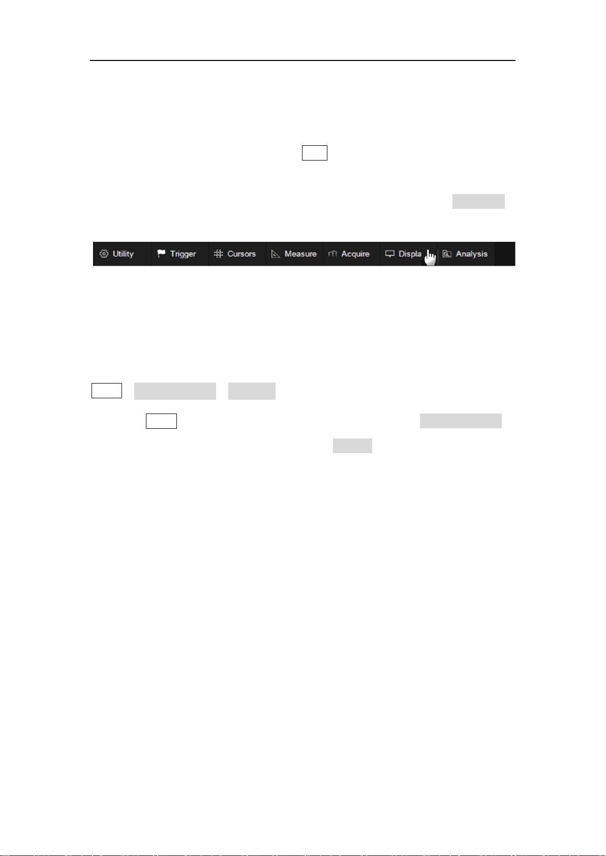
4 Document Conventions
For convenience, text surrounded by a box border is used to represent the
button of the front panel. For example, Print represents the "Print" button on
the front panel. Italicsized text with shading is used to represent the touchable
or clickable menu/button/region on the touch screen. For example, DISPLAY
represents the "DISPLAY" menu on the screen:
For the operations that contain multiple steps, the description is in the form of
"Step 1 > Step 2 > ...". As an example, follow each step in the sequence to
enter the upgrade interface:
Utility>System Setting>Upgrade
Press the Utility button on the front panel as step 1, click the System Setting
option on the screen as step 2, and click the Update option on the screen as
step 3 to enter the upgrade interface.
16 / 236 W W W. S I G L E NT. CO M

SDS5000X Series Digital Oscilloscope User Manual
5 Getting Started
5.1 Power on
SDS5000X provides two ways for power on, which are:
Power on Line
When the “Power on Line” option is enabled, once the oscilloscope is
connected to the AC power supply through the power cord, the oscilloscope
boots automatically. This is useful in automated or remote applications where
physical access to the instrument is difficult/impossible.
Steps for enabling the "Power on Line" function:
Utility>Power On Line
Power on by Manual
When the "Power on Line" option is disabled, the power button on the front
panel is the only control for the power state of the oscilloscope.
5.2 Shut down
Long press the power button for two seconds to turn off the oscilloscope.
Note:
The Power button does not disconnect the oscilloscope from the AC power
17 / 236 W W W. S I G L E NT. CO M

SDS5000X Series Digital Oscilloscope User Manual
supply. The only way to fully power down the instrument is to unplug the AC
power cord from the outlet. The power cord should be unplugged from the AC
outlet if the scope is not to be used for an extended period of time.
5.3 System Status
Follow the steps below to examine the software and hardware versions of the
oscilloscope.
Utility>System Setting>System Status
See the section "System Status" for details.
5.4 Install Options
A license is necessary to unlock a software option. See the section "Install
Option" for details.
18 / 236 W W W. S I G L E NT. CO M

SDS5000X Series Digital Oscilloscope User Manual
6 Probe
The SDS5000X series oscilloscope package includes passive probes as
standard accessories. Please visit the website at www.siglent.com for
technical data and ordering information.
Probe Compensation
When a probe is used for the first time, you should compensate it to match the
input channel of the oscilloscope. Non-compensated or poorly compensated
probe may increase measurement inaccuracy or error. The probe
compensation procedures are as follows:
1. Connect the coaxial cable interface (BNC connector) of passive probe
to any channel of the oscilloscope.
2. Connect the probe to the “Compensation Signal Output Terminal”
(Cal) on the front of the oscilloscope. Connect the ground alligator clip
of the probe to the “Ground Terminal” under the compensation signal
output terminal.
3. Press the Auto Setup button.
4. Check the waveform displayed and compare it with the following.
19 / 236 W W W. S I G L E NT. CO M

SDS5000X Series Digital Oscilloscope User Manual
Under
Compensated
Perfectly
Compensated
Over
Compensated
5. Use a non-metallic driver to adjust the low-frequency compensation
adjustment hole on the probe until the waveform displayed is as the
“Perfectly compensated” in the figure above.
20 / 236 W W W. S I G L E NT. CO M
SDS5000X Series Digital Oscilloscope User Manual
7 Quick Start
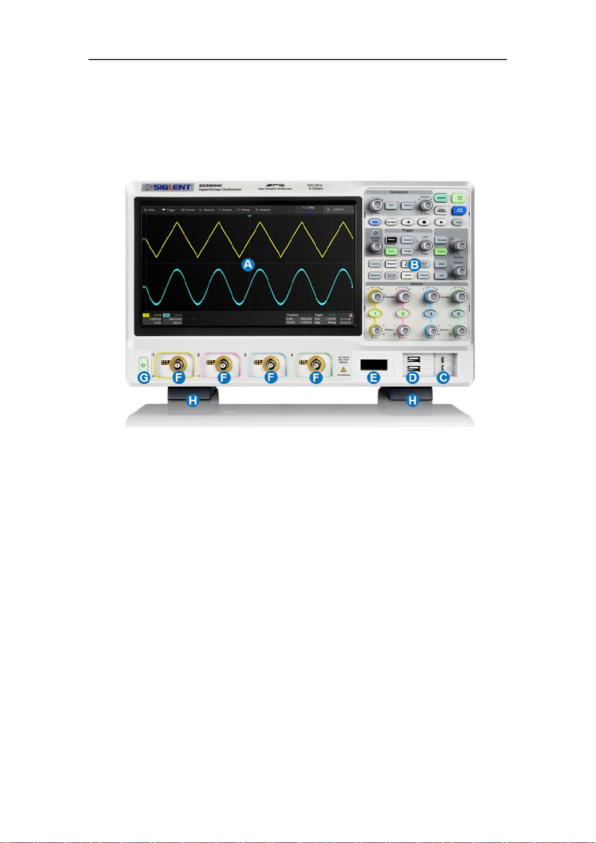
7.1 Front Panel Overview
A. Touch Screen Display: The display and major functions area. See
"Touch Screen Display" chapter for more details.
B. Front Panel: Includes knobs and buttons. See "Front Panel" chapter
for more details.
C. Probe Compensation/ Ground Terminal: Supplies a 0-3 V 1 kHz
square wave for compensating the probes.
D. USB Host Ports: Connect the USB host ports to USB storage
devices for data transfer, or USB mouse / keyboard for control.
E. Digital Input Connector: Receives digital signals from the SPL2016
digital probe.
F. Analog Input Connectors
21 / 236 W W W. S I G L E NT. CO M
SDS5000X Series Digital Oscilloscope User Manual
G. Power Switch
H. Supporting Legs: Adjust the supporting legs properly to use them as
stands to tilt the oscilloscope for stable positioning of the oscilloscope.
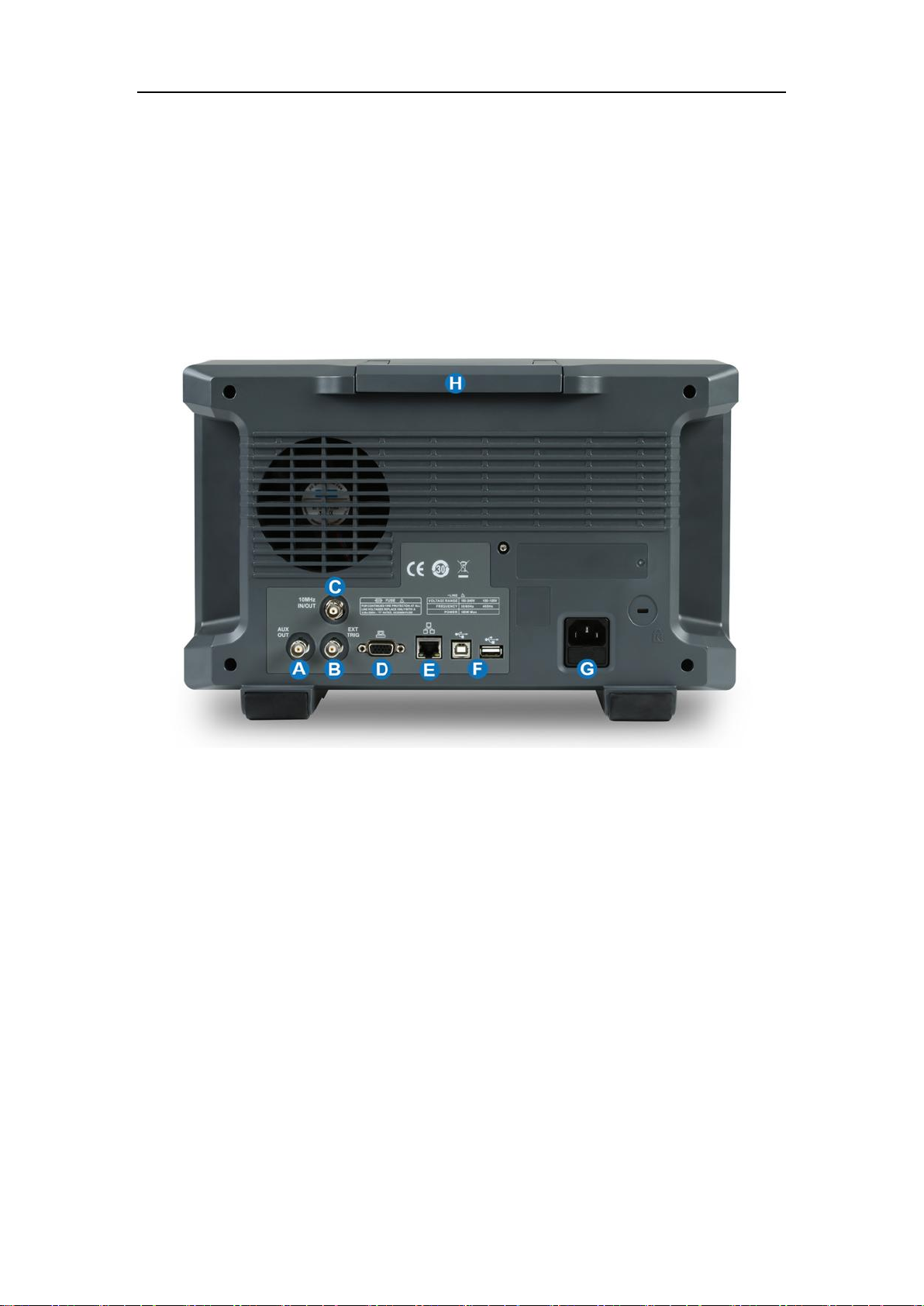
7.2 Rear Panel Overview
A. Auxiliary Out: Outputs the trigger indicator. When Pass / Fail is
enabled, outputs the pass / fail signal.
B. Ext Trigger Input
C. 10 MHz Clock Input/Output: Receives or outputs 10 MHz reference
clock for synchronization between the oscilloscope and other
instruments.
D. VGA Video Output: Connect the port to an external monitor. The
resolution is 1024 * 600.
E. LAN Port: Connect the port to the network for remote control.
22 / 236 W W W. S I G L E NT. CO M

SDS5000X Series Digital Oscilloscope User Manual
F. USB Ports: One USB device to connect with a PC for remote control
and one USB host to connect with a USB storage device or USB
mouse / keyboard.
G. AC Power Input
H. Handle
23 / 236 W W W. S I G L E NT. CO M

SDS5000X Series Digital Oscilloscope User Manual
7.3 Connecting to External Devices/Systems
7.3.1 Power Supply
The standard power supply for the instrument is 100~240 V, 50/60 Hz or
100~120 V, 400 Hz. Please use the power cord provided with the instrument
to connect it to AC power.
7.3.2 LAN
Connect the LAN port to the network with a network cable with RJ45 head for
remote control.
Follow the steps below to set LAN connection:
Utility>System Setting>I/O>LAN Config
7.3.3 USB Peripherals
Connect a USB storage device (FAT32 format) to one of the USB host ports
for data transfer, or connect USB mouse / keyboard to one of the USB host
ports for controlling the instrument.
7.3.4 External Monitor
Use a D-Sub cable to connect the VGA port to an external monitor. The video
signal from the VGA port has a 1024 * 600 resolution.
24 / 236 W W W. S I G L E NT. CO M

SDS5000X Series Digital Oscilloscope User Manual
7.3.5 Auxiliary Output
When Pass / Fail is enabled, the port outputs the pass / fail signal, otherwise it
outputs the trigger indicator.
See the chapter "Pass/Fail " for more details.
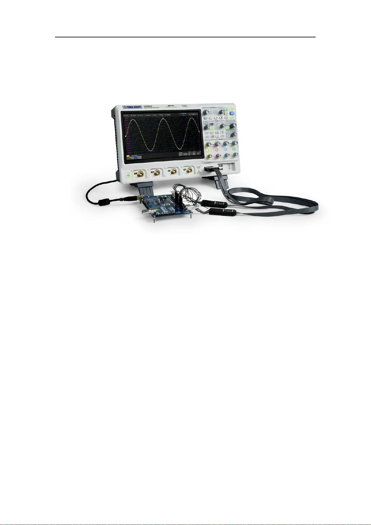
7.3.6 SAG1021 Waveform Generator
Activate the SDS-5000X-FG option and connect the SAG1021 USB function /
arbitrary waveform generator module to any USB host pot on the oscilloscope.
The oscilloscope can now control the USB module to output specified
waveforms.
Press the WaveGen button on the front panel or touch the screen Utility
>
AWG Menu to set the waveform.
7.3.7 Probes
The SDS5000X series oscilloscope supports active probe and passive
probes. The specifications and documents of the probe can be obtained at
www.siglent.com.
25 / 236 W W W. S I G L E NT. CO M
SDS5000X Series Digital Oscilloscope User Manual
7.3.8 Logic Probe
To connect the logic probe: Insert the probe, with the correct side facing up,
until you hear a “click”.
To remove the logic probe: Depress the buttons on each side of the probe,
then pull out it.
26 / 236 W W W. S I G L E NT. CO M

SDS5000X Series Digital Oscilloscope User Manual
8 Touch Screen Display
8.1 Overview
The entire SDS5000X display is a capacitive touch screen. Use your fingers to
touch, drag, pinch, spread, or draw a selection box. Many controls that display
information also work as “buttons” to access other functions. If you using any
mouse, you can click anywhere – that you can touch - to activate a control; in
fact, you can alternate between clicking and touching the control, whichever is
convenient.
A. Menu Bar
B. Grid Area
C. Trigger Level Indicator
D. Cursors
E. Channel Descriptor box descriptor boxes
27 / 236 W W W. S I G L E NT. CO M

SDS5000X Series Digital Oscilloscope User Manual
F. Trigger Delay Indicator
G. Timebase and Trigger descriptor box
H. Dialog Box
Trigger Level Line (Vertical) and Trigger Delay Indicator (Horizontal) show
the trigger position of the waveform.
Cursors show where measurement points have been set. Move the cursors
to quickly reposition the measurement point.
Channel Descriptor boxes include analog channels (C1 ~ C4), digital
channels (D), math (M) and reference (Ref). They are located under the grid
area, showing the parameters of the corresponding traces. Touching the
boxes creates a dialog box.
Timebase and Trigger Descriptor boxes show the parameters of the
timebase and trigger respectively. Touching the boxes creates a dialog box for
the selected item.
8.2 Menu Bar
Menu bar with drop-down menus lets you access set-up dialogs and other
functions. All functionality can be accessed through the menu bar. It is not
necessary for common operations. You can enter most menus by using the
front panel or parameter description labels instead of the menu bar. However,
the following operations can only be accessed through the menu bar:
28 / 236 W W W. S I G L E NT. CO M
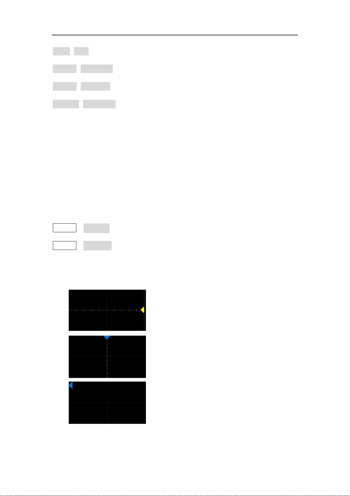
SDS5000X Series Digital Oscilloscope User Manual
Trigger Level Indicator shows the level
where the waveform triggers on the vertical
axis.
Trigger Delay Indicator locates where the
waveform triggers on the horizontal axis...
When the trigger position is outside the
screen, the direction of the triangle changes
to point outside the screen.
Utility>Help
Acquire>Sequence
Acquire>XY Mode
Analysis>Pass/Fail
8.3 Grid Area
The grid area displays the waveform traces. Traces can be moved by
dragging, and re-scaled by pinch and spread. The area is divided into 8
(vertical) * 10 (horizontal) grids. The best display effect can be obtained by
adjusting the waveform intensity and graticule. Follow the steps below to set
these parameters:
Display>Intensity,
Display>Graticule
There are multiple indicators on the grid:
29 / 236 W W W. S I G L E NT. CO M
SDS5000X Series Digital Oscilloscope User Manual
Channel Offset Indicator with a channel
number shows the offset position of the
corresponding channel.
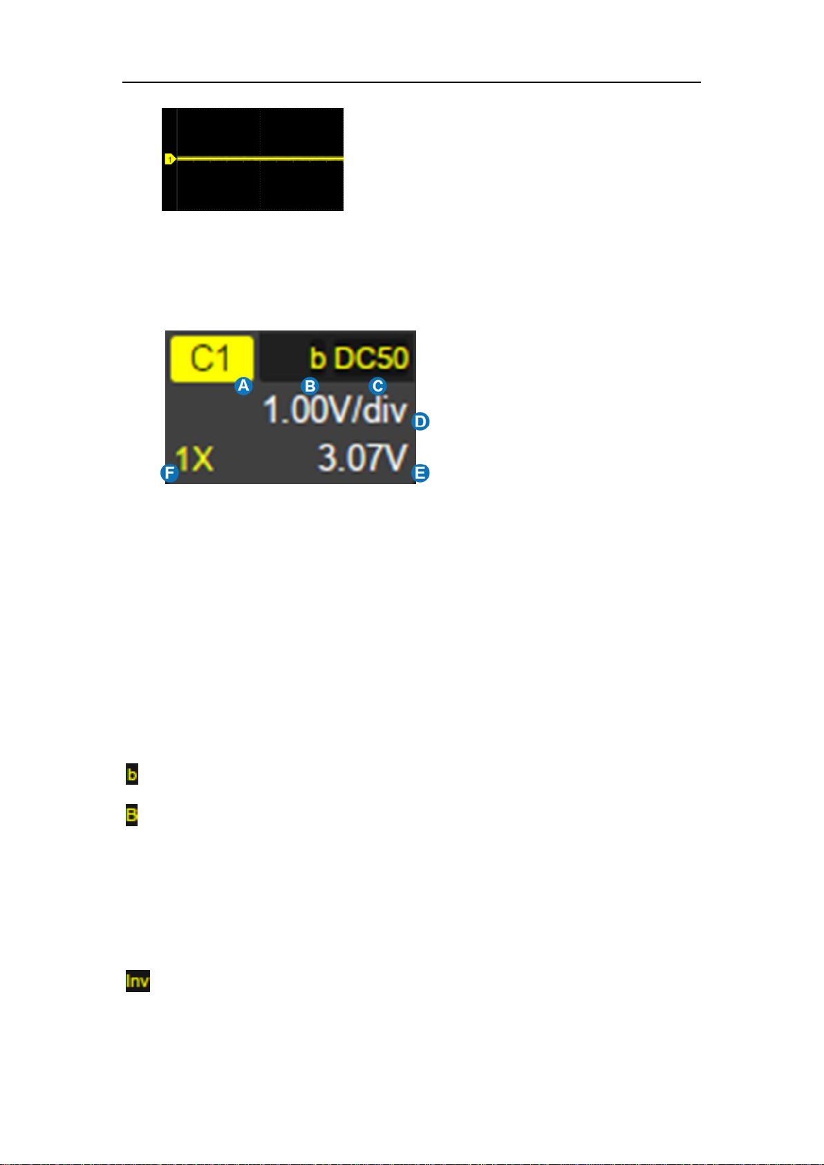
A. Channel Index
B. Bandwidth Limit
indicator
C. Coupling and Input
Impedance
D. Vertical Scale
E. Vertical Offset
F. Probe Attenuation
Factor
8.4 Channel Descriptor Box
Bandwidth Limit Indicators:
The SDS5000X has two available bandwidth limits: 20 and 200 MHz. They are
indicated by the following icons:
:20 MHz bandwidth limit
:200 MHz bandwidth limit
None: Full bandwidth
Invert Indicator -- shows that the current channel is inverted:
: Invert has been turned on
None: Invert has been turned off
30 / 236 W W W. S I G L E NT. CO M
 Loading...