

SIGLENT SDS2000X Service Manual

Service Manual
SDS2000X Series Digital Oscilloscope
2017 SIGLENTTECHNOLOGIES CO., LTD


SIGLENT
SDS1000X+ Service Manual I
Guaranty and Declaration
Copyright
SIGLENT TECHNOLOGIES CO., LTD All Rights Reserved.
Trademark Information
SIGLENT is the registered trademark of SIGLENT TECHNOLOGIES CO.,
LTD
Declaration
SIGLENT products are protected by patent law in and outside of P.R.C.
SIGLENT reserves the right to modify or change parts of or all the
specifications or pricing policies at company‟s sole decision.
Information in this publication replaces all previously corresponding
material.
Any method of copying, extracting or translating the contents of this
manual is not allowed without the permission of SIGLENT.
SIGLENT will not be responsible for losses caused by either incidental or
consequential reasons in connection with the furnishing, use or
performance of this manual as well as any information contained.
Product Certification
SIGLENT guarantees this product conforms to the national and industrial
standards in China as well as the ISO9001: 2008 standard and the
ISO14001: 2004 standard. Other international standard conformance
certification is in progress.

SIGLENT
II SDS2000X Service Manual
General Safety Summary
Review the following safety precautions to avoid personal injuries and
prevent damages to this product or any products connected to it. To avoid
potential hazards, use this product only as specified.
Only qualified personnel should perform service procedures.
To Avoid Fire or Personal Injuries
Use Proper Power Cord. Use only the power cord specified for this product
and approved by your local governing agencies.
Avoid Electric Shock. To avoid injuries or potential loss of life, do not
connect or disconnect probes or test leads while they are connected to a
voltage source.
Ground the Product. This product is grounded through the protective
ground conductor of the power line. To avoid electric shock, the grounding
conductor must be connected to the earth ground. Make sure the instrument
is grounded correctly before connecting its input or output terminals.
Connect the Probe Properly. Do not connect the probe ground lead to a
high voltage since it has the isobaric electric potential as ground.
Observe All Terminal Ratings. To avoid fire or shock hazard, observe all
ratings and markings on the instrument and check your manual for more
information about ratings before connecting.
Use Proper Fuse. Use only the specified fuse.
Do Not Operate Without Covers. Do not operate this instrument with
covers or panels removed.

SIGLENT
SDS2000X Service Manual III
Avoid Circuit or Wire Exposed. Do not touch exposed junctions and
components when the unit is powered.
Do Not Operate With Suspected Problems. If you suspect damage has
occurred to this instrument, have it inspected by qualified service personnel
before further operation. Any maintenance, adjustment or replacement,
especially to the circuits or accessories should be performed by SIGLENT
authorized personnel.
Keep Product Surfaces Clean and Dry.
Do Not Operate in Wet/Damp Conditions. To avoid electric shock, do not
operate the instrument in wet or damp conditions.
Do Not Operate in an Explosive Atmosphere. To avoid injuries or fire
hazards, do not operate in an explosive atmosphere.
Safety Terms and Symbols
Terms on the Product. These terms may appear on the product:
DANGER: Indicates an injury or hazard that may immediately happen.
WARNING: Indicates an injury or hazard may be potentially accessible.
CAUTION: Indicates damage to the instrument or other property may occur.
Symbols on the Product. These symbols may appear on the product:


SIGLENT
SDS2000X Service Manual 1
Contents
Guaranty and Declaration ................................................................................................................. I
General Safety Summary ................................................................................................................. II
General Features ............................................................................................................................... 3
General Features ....................................................................................................................... 3
Prepare Information .......................................................................................................................... 6
Functional checking .................................................................................................................. 6
Power-on Inspection .......................................................................................................... 6
Probe Compensation ......................................................................................................... 8
Auto Setup ......................................................................................................................... 9
Self Calibration ............................................................................................................... 10
Interface Test ........................................................................................................................... 12
USB Host Test ................................................................................................................. 12
USB Device Test ............................................................................................................. 13
LAN Port Test ................................................................................................................. 14
Pass/Fail out Test ............................................................................................................. 16
Performance Test ............................................................................................................................ 18
To Verify DC Gain Accuracy .................................................................................................. 23
To Verify Offset Accuracy ....................................................................................................... 25
To Verify Time Base Accuracy ................................................................................................ 27
To Verify Trigger Delay .......................................................................................................... 28
To Verify Ext Trigger Delay .................................................................................................... 29
To Verify Ext Trigger Level .................................................................................................... 30
To Verify Noise Floor .............................................................................................................. 31
To Verify Bandwidth ............................................................................................................... 32
To Verify Bandwidth Limit ..................................................................................................... 34
To Verify Trigger Sensitivity ................................................................................................... 35
To Verify Input Impedance ...................................................................................................... 37
To Verify AWG ........................................................................................................................ 38
Adjusting Procedures ...................................................................................................................... 40
Warming Up ............................................................................................................................ 40
Self Calibration ....................................................................................................................... 40
Required Equipment ............................................................................................................... 40
Software Installation ............................................................................................................... 41
Adjusting Steps ....................................................................................................................... 41
Assembly Procedures ...................................................................................................................... 44
Security Considerations .......................................................................................................... 44
List of Modules ....................................................................................................................... 44
Required Tools ........................................................................................................................ 45
Disassembly Procedures.......................................................................................................... 46
Removing the Front-Panel Knobs ................................................................................... 46
Removing the Rear Panel ................................................................................................ 47
Removing the Rear Metal Cover ..................................................................................... 49
Removing the Front Panel ............................................................................................... 50
Removing the LCD, Channel Board and Keyboard ........................................................ 51
Removing the Main Board .............................................................................................. 52
Troubleshooting Hardware Failures ........................................................................................ 54
ESD Precautions.............................................................................................................. 54
Required Equipment........................................................................................................ 54
Main Board Drawing....................................................................................................... 55
Troubleshooting Flowchart ............................................................................................. 56
Check the Power Supply ................................................................................................. 58
Check the Main Board .................................................................................................... 59
Check the Display Module .............................................................................................. 60

SIGLENT
2 SDS2000X Service Manual
Handling General Hardware Failures .............................................................................. 61
Contact SIGLENT........................................................................................................................... 62

SIGLENT
SDS2000X Service Manual 3
General Features
General Features
SIGLENT‟s SDS2000X series Super Phosphor Oscilloscopes are available in
bandwidths of 70 MHz, 100 MHz, 200 MHz and 300 MHz, utilize a maximum
sample rate of 2 GSa/s and a maximum record length of 140 Mpts. The most
commonly used functions can be accessed with its user-friendly one-button
design.
The SDS2000X series employs a new generation of SPO technology. It
employs an innovative digital trigger system with high sensitivity and low jitter.
The maximum waveform capture rate is 140,000 wfm/s (normal mode) and up
to 500,000 wfm/s (sequence mode). It also employs not only the
more-common 256-level intensity grading display function but also a powerful
color temperature display mode. The SDS2000X‟s trigger system supports
multiple powerful triggering modes including serial bus triggering. History
waveform recording and sequence acquisition allow for extended waveform
records to be captured, stored, and analyzed. An impressive array of
measurement and math capabilities, options for a built-in 25 MHz arbitrary
waveform generator, 16 digital channels (MSO), as well as serial decoding are
also features of the SDS2000X.
Table 1 General features
Model
Bandwidth
Sampling Rate
Memory Depth
Channel
SDS2072X
70 MHz
2 GS/s
140 Mpts
2
SDS2074X
70 MHz
2 GS/s
140 Mpts
4
SDS2102X
100 MHz
2 GS/s
140 Mpts
2
SDS2104X
100 MHz
2 GS/s
140 Mpts
4
SDS2202X
200 MHz
2 GS/s
140 Mpts
2

SIGLENT
4 SDS2000X Service Manual
SDS2204X
200 MHz
2 GS/s
140 Mpts
4
SDS2302X
300 MHz
2 GS/s
140 Mpts
2
SDS2304X
300 MHz
2 GS/s
140 Mpts
4
70 MHz, 100 MHz, 200 MHz, 300 MHz models
Real-time sampling rate up to 2 GSa/s
New generation of SPO technology
Waveform capture rate up to 140,000 wfm/s (normal mode), and 500,000 wfm/s
(sequence mode)
Supports 256-level intensity grading and color temperature display
Record length up to 140 Mpts
Digital trigger system
Intelligent trigger: Edge, Slope, Pulse, Window, Runt, Interval, Dropout,
Pattern and Video (HDTV supported)
Serial bus triggering and decode, supports protocols IIC, SPI, UART,
RS232, CAN, LIN
Low background noise, supports 1 mV / div to 10 V / div voltage scales
10 types of one-button shortcuts; supports Auto Setup, Default Setup,
Cursor, Measure, Roll, History, Persist, Clear Sweep, Zoom and Print
Segmented acquisition (Sequence) mode. Divides the maximum record
length into multiple segments (up to 80,000), according to trigger
conditions set by the user - with a very small dead time segment - to
capture the qualifying event
History waveform record (History) function. The maximum recorded
waveform length is 80,000 frames
37 automatic measurement functions. Supports Statistics calculations,
Gating measurement, Math measurement, History measurement, Ref
measurement
Waveform math function (FFT, addition, subtraction, multiplication, division,
integration, differentiation, square root)
High Speed hardware-based Pass/ Fail function
25 MHz DDS arbitrary waveform generator - built-in 10 waveform functions
(Optional)

SIGLENT
SDS2000X Service Manual 5
Large 8 inch TFT-LCD display with 800 * 480 resolution. Multiple interfaces,
including USB Host, USB Device (USBTMC), LAN (VXI-11), Pass / Fail,
Trigger Out
Supports SCPI remote control commands
Supports Multi-language display and embedded online help

SIGLENT
6 SDS2000X Service Manual
Prepare Information
Before initiating performance verification or any adjustments, it is
recommended the user follow these procedures. The following topics are
discussed in this chapter.
How to perform functional checks
How to operate four standard interface tests
How to use self-calibration routine
How to recall factory Default settings
For more detailed information about oscilloscope operation, please refer to the
Quick Start Guide.
Functional checking
The functional checking details three types of checks used to determine if the
oscilloscope is operating properly.
Power-on Inspection
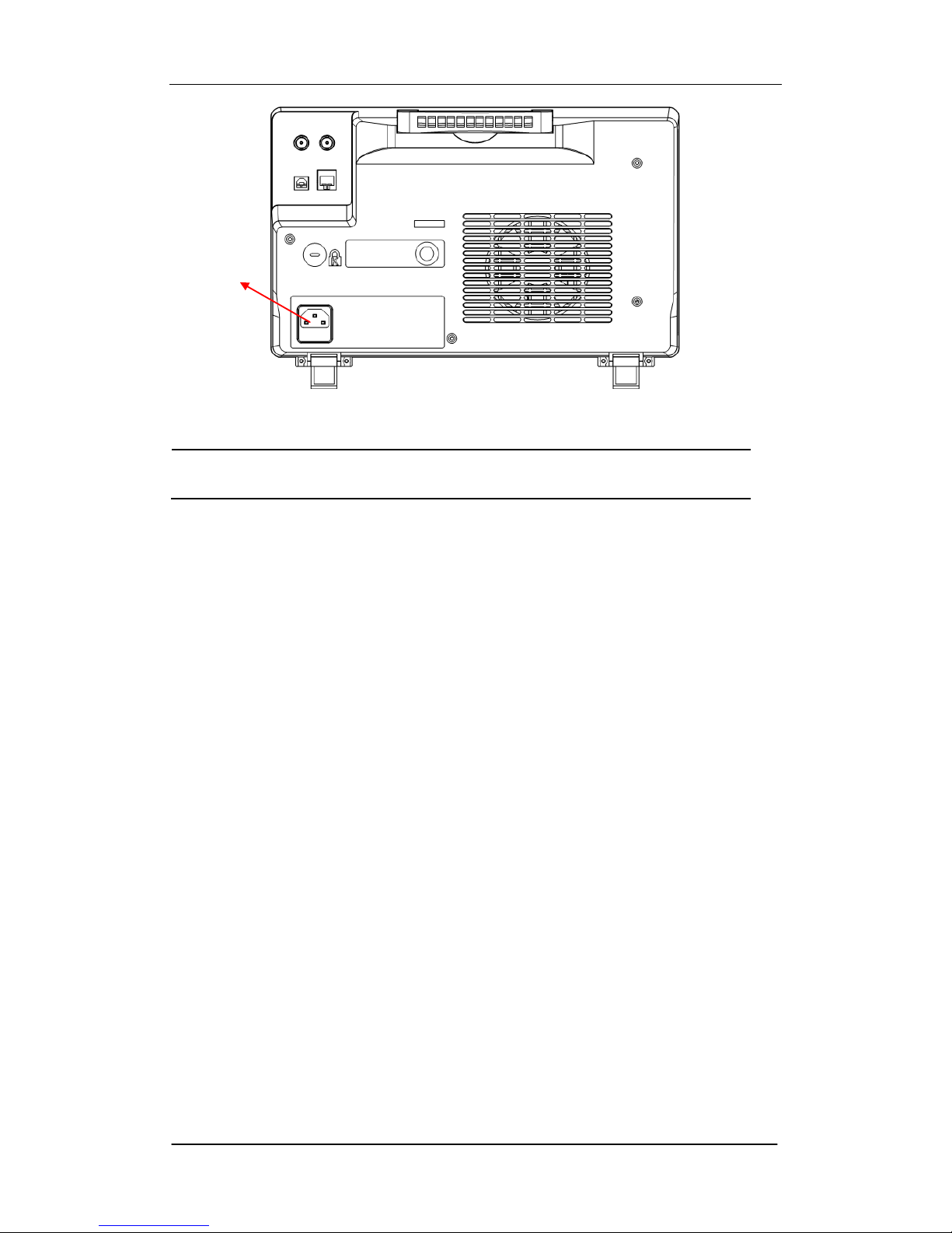
The normal operating voltage for the SDS2000X series digital oscilloscope is in
range of 100-240 VRMS ,50 Hz/ 60 Hz/ 440Hz. Connect the power cord to the
socket on the rear panel of the oscilloscope.
SIGLENT
SDS2000X Service Manual 7
Figure 1 Connect power cord
Note: To avoid electric shock, make sure that the instrument is
correctly grounded to the earth before connecting AC power.
Press the power-on button located at the lower left corner of the front panel
and note that several oscilloscope keys will be lighted for about 6 seconds
simultaneously, until the boot screen appears. The oscilloscope will then begin
to perform its power-on tests automatically, after which the DEFAULT SETUP
button can be pressed in order to recall the factory default settings.
The socket
SIGLENT
8 SDS2000X Service Manual
Probe Compensation
It is necessary to compensate the probe at first use so as to properly match the
probe to the oscilloscope‟s input channel. Non-compensated or poorly
compensated probes may cause measurement inaccuracies or errors. The
probe compensation steps are as follows:
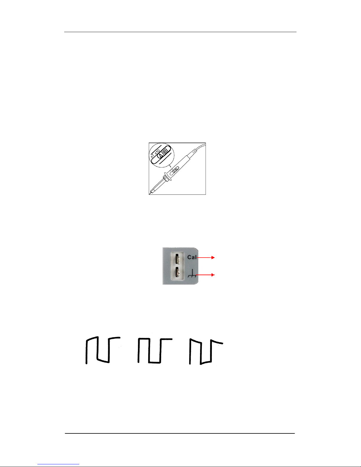
1. Set the attenuation switch on the probe to 10X.
Figure 2 Set the attenuation switch
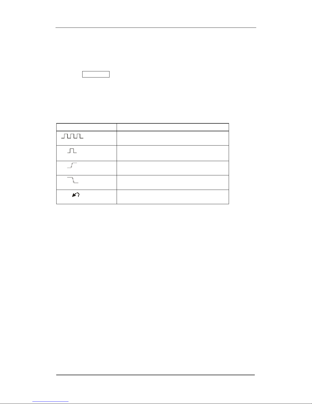
2. Connect the alligator clip of the probe to the Ground Terminal on the front
panel, and then use the probe to connect CH1 BNC input connector to the
Compensation Signal Output Terminal.
3. Press AUTO Setup.
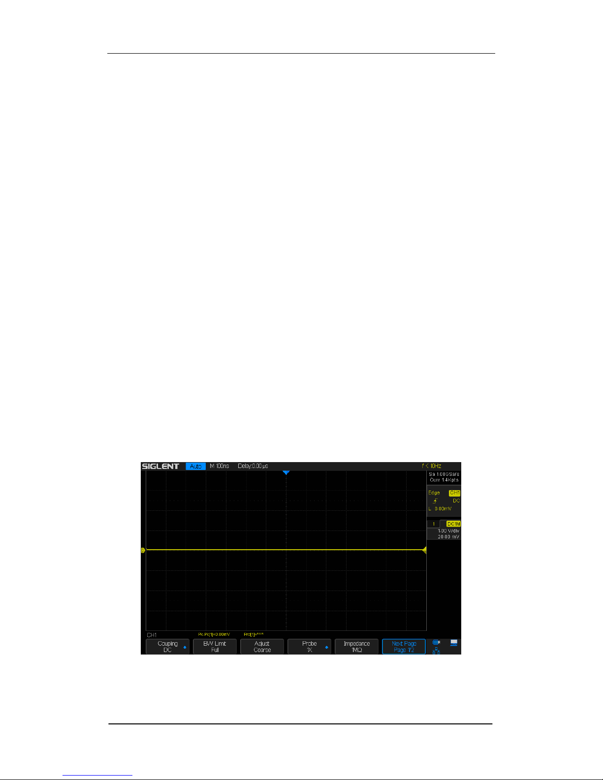
4.Observe waveform on the screen. The displaying should be a square
waveform as shown in the figure below:
Under Compensated Over
Compensated Correctly Compensated
5. If the waveform does not show as “compensated correctly”, use a
nonmetallic screwdriver to adjust the low-frequency compensation
adjustment hole on the probe until the waveform displays correctly.
Ground Terminal
Compensation Terminal
SIGLENT
SDS2000X Service Manual 9
Auto Setup
Press the Auto Setup key to enable the waveform auto setting function. The
oscilloscope will automatically adjust the horizontal time base, vertical scale
and trigger mode according to the input signal to obtain an optimum waveform
display.
Table 2 Auto setting menu
Option
Introduction
(Multi-cycle sine)
Display several waveform cycles
(Single-cycle sine)
Display single waveform cycles
(Rising edge)
Display the rising edge of waveform
(Falling edge)
Display the falling edge of waveform
(Undo Setup)
Recall the previous setup of oscilloscope
The input signal frequency must be higher than 20 Hz, with the amplitude
greater than 8 mV.
Select the channel with the lowest frequency when several channels are
connected to signals.
SIGLENT
10 SDS2000X Service Manual
Self Calibration
The self-calibration routine can quickly adjust the oscilloscope to perform at
the optimum state in order to achieve the maximum accuracy. Self-calibration
can be performed at any time, especially when a change in the ambient
temperature of 5℃ or more has occurred. Make certain that the oscilloscope
has been warmed up or operated for more than 30 minutes before performing
the self-calibration.
Use the following steps to perform self calibration:
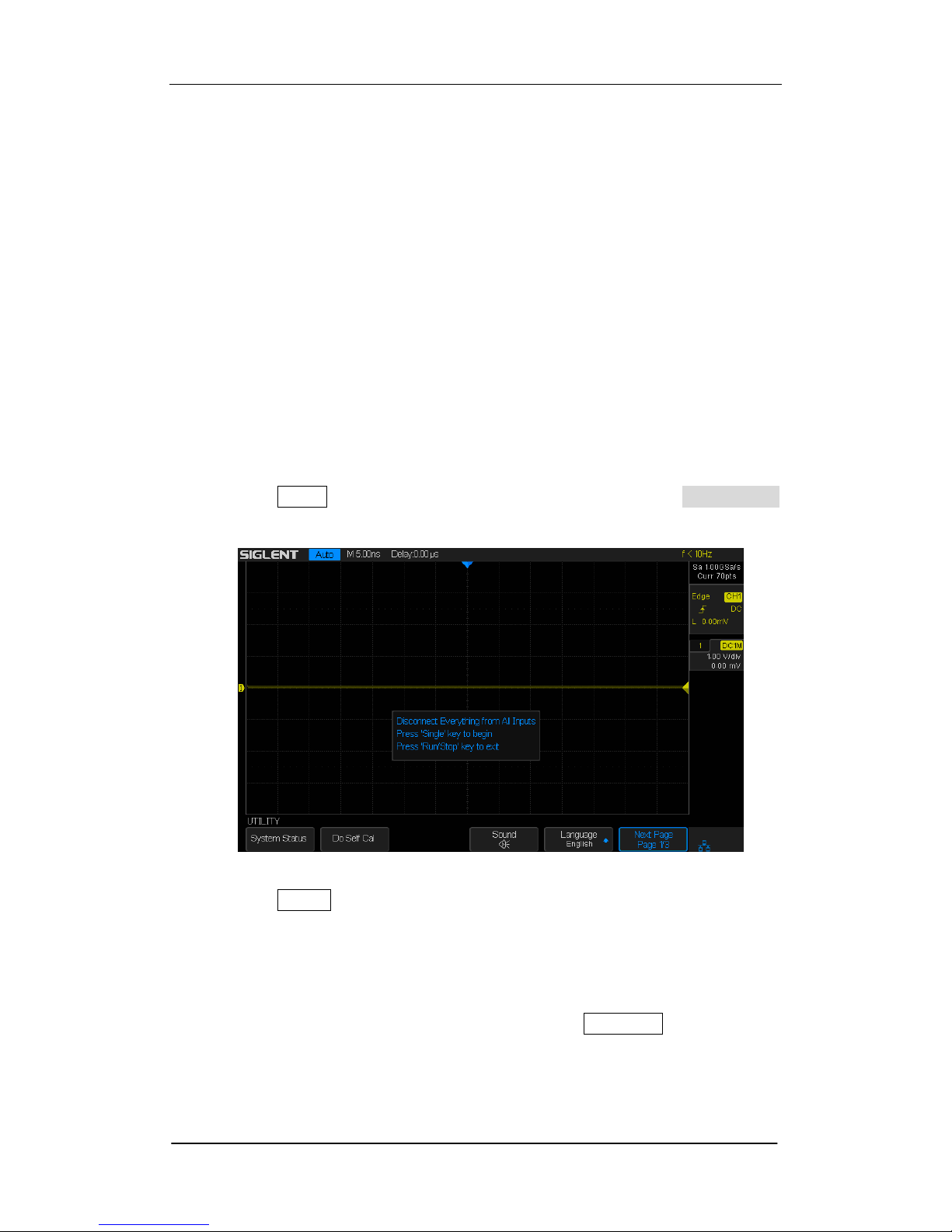
1. Disconnect all leads from all input channels.
2. Press the Utility button on the front panel, and then press the Do Self Cal
softkey. The oscilloscope will display the message box as shown below:
Figure2-3 Calibration Interface
3. Press the Single button on the front panel to perform the self calibration
program. During the calibration, most of the oscilloscope‟s keys are
disabled.
4. When the self calibration process is completed, the following message will
appear: “Press Run/Stop key to exit”. Press the Run/Stop button on the
front panel to exit the calibration interface.
Note: Under normal conditions the self-calibration procedure will take

SIGLENT
SDS2000X Service Manual 11
approximately 20 seconds. If it does not complete within this period of time or it
stops on one of the calibration settings, then there may be a problem with the
instrument.
SIGLENT
12 SDS2000X Service Manual
Interface Test
The SDS2000X series oscilloscope is designed with four standard interfaces:
USB Host, USB Device, LAN and Pass/Fail. Connecting to other instruments
via these interfaces enables the oscilloscope to achieve additional capabilities.
In order to ensure the oscilloscope is operating properly it is recommended
that the user first test the interfaces.
USB Host Test
To test whether the USB Host interface is operating correctly.
Tools:
● A U disk
Steps:
1. Insert a U disk (flash drive) into the USB Host interface on the front panel of
the oscilloscope.
2. A message prompt “USB Flash Drive Plug In!”,appears on the screen, and
an icon will be shown in the lower right corner of the screen which confirms
the U disk has been successfully recognized.
Figure 3 USB drive in interface
SIGLENT
SDS2000X Service Manual 13
USB Device Test
To test if the USB Device interface operating correctly.
Tools:
● A computer with USB interface
● A standard USB cable (Type AB)
● NI Max software
Steps:
1. Set up NI Max software in a computer and Install the driver step by step
following the instructions.
2. Connect the oscilloscope to the computer using an USB cable.
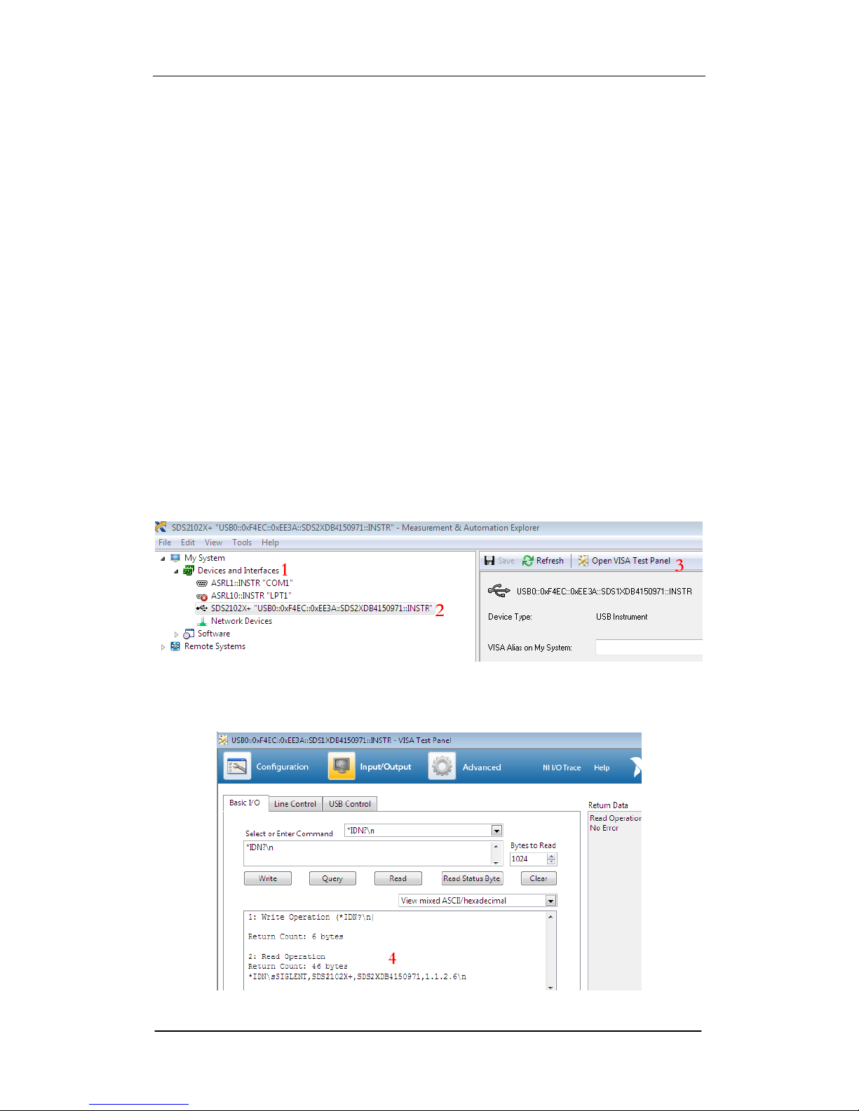
3. Run NI Max software. Click “Device and Interface” at the upper left corner of
the NI software interface and immediately the “USBTMC” device symbol is
displayed.
4. Click “Open VISA Test Panel” option button, and then the following Interface
will appear. Next, click the “Input/Output” option button and click the “Query”
option button in order to view the Read operation information.
SIGLENT
14 SDS2000X Service Manual
LAN Port Test
Use to test if the LAN interface operates correctly when connected with NI Visa
software.
Tools:
● A computer with LAN interface
● A standard LAN cable
●NI Max software
Steps:
1. Set up NI Max software in a computer and install the driver using the
following instructions.
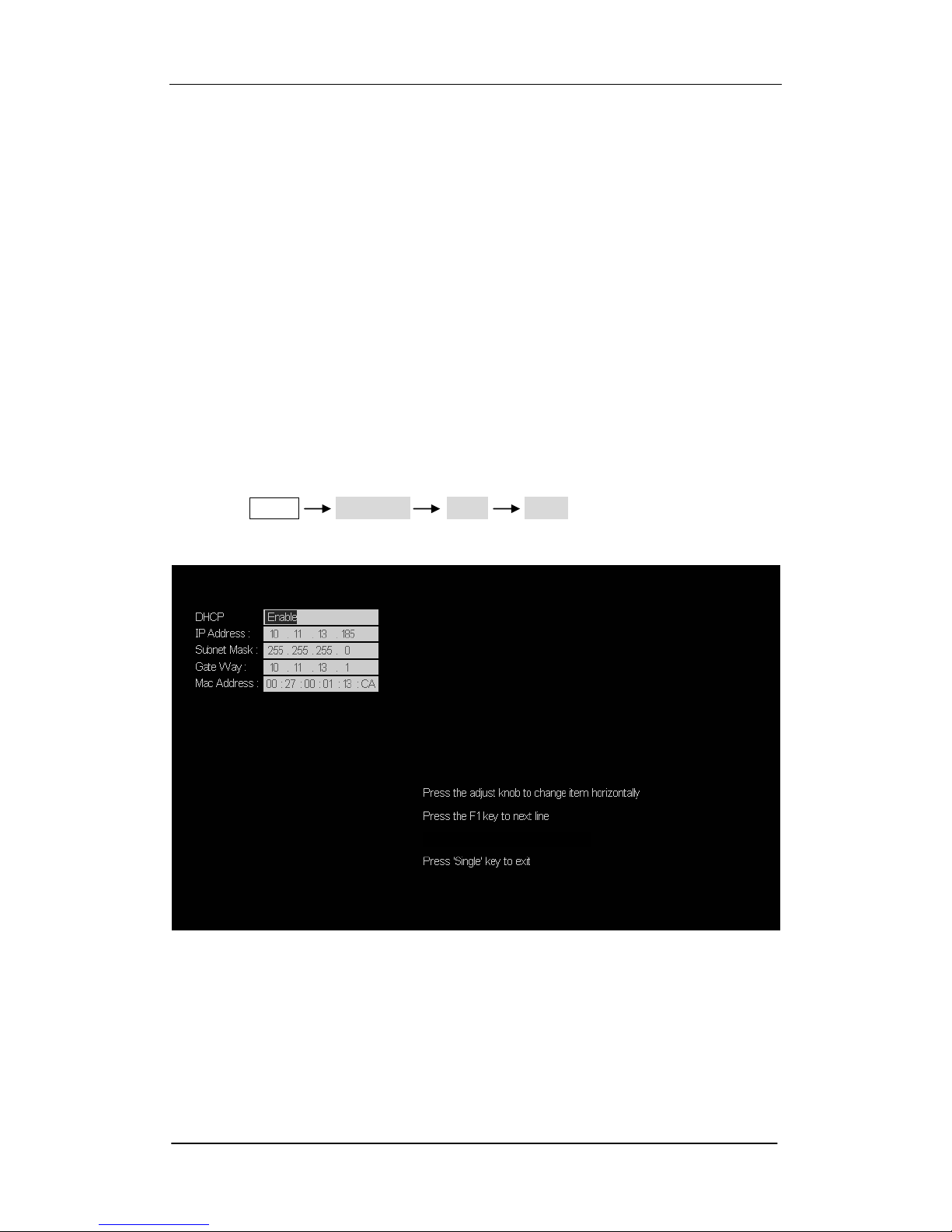
2. Press Utility Page2/3 I/O LAN, input usable IP Address
and Subnet Mask.
Figure 4 IP Setting interface
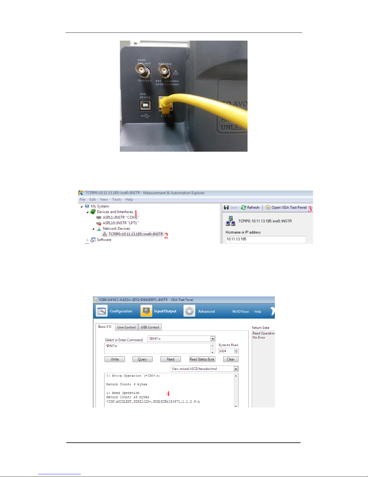
3. Connect the oscilloscope to the computer using a LAN cable via the LAN
interface ports.
SIGLENT
SDS2000X Service Manual 15
Figure 5 LAN interface
4. Run NI Max software. Click “Device and Interface” at the upper left corner of
the NI software interface and select the “LAN” device symbol.
5. Click “Open VISA Test Panel” option button, which then displays the
following interface (below). Then click the “Input/Output” option button and
click the “Query” option button;. The Read operation information will be
displayed.
 Loading...