

Page 1
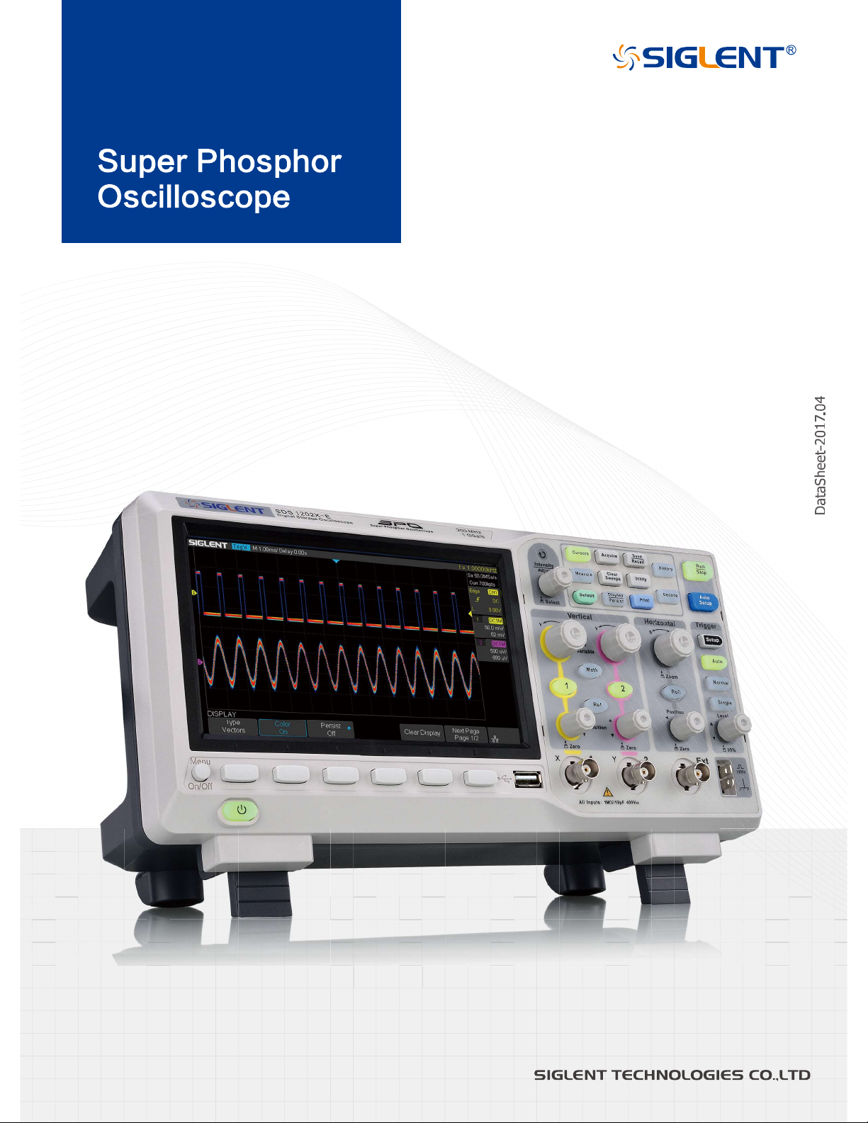
SDS1000X-E
Series
Page 2
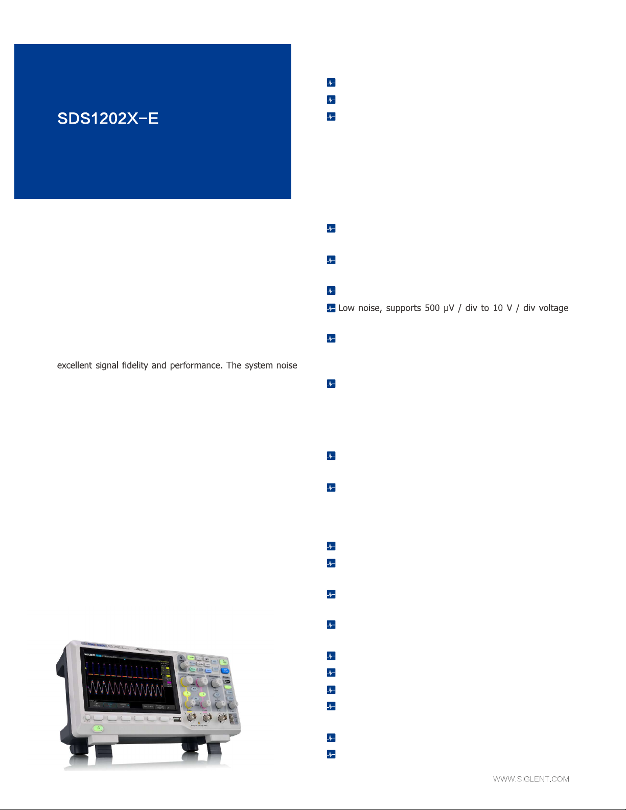
Product overview
SIG L E N T’s ne w SDS1000X-E Series Super P h os phor
Oscilloscope is available in one bandwidth, 200 MHz. It has
a maximum sample rate of 1 GSa/s and a standard record
length of 14 Mpts. For ease-of-use, the most commonly
used functions can be accessed with its user-friendly front
panel design.
The SDS1000X-E series employs a new generation of SPO
(Super Phosphor Oscilloscope) technology that provides
is also lower than similar products in the industry. It comes
with a minimum vertical input range of 500 uV/div, an
innovative digital trigger system with high sensitivity and
low jitter, and a waveform capture rate of 400,000 frames/
sec (sequence mode). The SDS1000X-E also employs a
256-level intensity grading display function and a color
temperature display mode not found in other models in
this class. Siglent’s latest oscilloscopes offering supports
multiple powerful triggering modes including serial bus
triggering. Decoding is standard configuration including
IIC,SPI,UART,CAN,LIN. History waveform reco rding and
sequential triggering enable extended waveform recording
and analysis. Another powerful addition is the new 1 million
points FFT math function that gives the SDS1000X-E very
high frequency resolution when observing signal spectra.
The new design also includes a hardware co-processor that
delivers measurements quickly and accurately. The features
and performance of Siglent’s new SDS1000X-E cannot be
matched anywhere else in this price class.
SDS1000X-E Series Digital Oscilloscope
Key Features
200 MHz bandwidth model
Real-time sampling rate up to 1 GSa/s
The newest generation of SPO technology
•Waveform capture rate up to 100,000 wfm/s (normal
mode), and 400,000 wfm/s (sequence mode)
•Supports 256-level intensity grading and color display
modes
•Record length up to 14 Mpts
•Digital trigger system
Intelligent triggers: Edge, Slope, Pulse Width, Window,
Runt, Interval, Time out (Dropout), Pattern
Serial bus triggering and decoding (Standard), supports
IIC, SPI, UART, RS232, CAN, and LIN
Video trigger, supports HDTV
scales
10 types of one-button shortcuts, supports Auto Setup,
Default, Cursors, Measure, Roll, History, Display/Persist,
Clear Sweep, Zoom and Print
Segmented acquisition (Sequence) mode, dividing the
maximum record length into multiple segments (up to
80,000), according to trigger conditions set by the user,
with a very small dead time segment to capture the
qualifying event
History waveform record (History) function, the maximum
recorded waveform length is 80,000 frames
Automatic measurement function for 38 parameters,
supp o r ts Stat i s ti cs , Zoom mea s u re me nt , Gati n g
measurement, Math measurement, History measurement
and Ref measurement
1 Mpoints FFT
True measurement and math of all sampled data points (to
14M)
Math functions (FFT, addition, subtraction, multiplication,
division, integration, differential, square root)
Preset key can be customized for user settings or factory
“defaults”
Security Erase mode
High Speed hardware based Pass/Fail function
Large 7 inch TFT-LCD display with 800 * 480 resolution
Multiple interface types: USB Host, USB Device (USB-
TMC), LAN (VXI-11), Pass/Fail, Trigger Out
Supports SCPI remote control commands
Supports Multi-language display and embedded online
help
Page 3
SDS1000X-E Series Digital Oscilloscope
Model SDS1202X-E
Bandwidth 200 MHz
Sampling Rate (Max.) 1 GSa/s
Channels 2+EXT
Memory Depth (Max.) 7 Mpts/CH (Dual-Channel); 14 Mpts/CH (Single-Channel)
Waveform Capture Rate (Max.) 100,000 wfm/s (normal mode), 400,000 wfm/s (sequence mode)
Trigger Type Edge, Slope, Pulse Width, Window, Runt, Interval, Dropout, Pattern, Video
Serial Trigger (Standard) IIC, SPI, UART/RS232, CAN, LIN
Decode Type (Standard) IIC, SPI, UART/RS232, CAN, LIN
I/O USB Host, USB Device, LAN, Pass/Fail, Trigger Out
Probe (Std) 2 pcs passive probe PP215
Display 7 inch TFT-LCD (800x480)
Weight Without package 2.5 Kg; With package 3.5 Kg
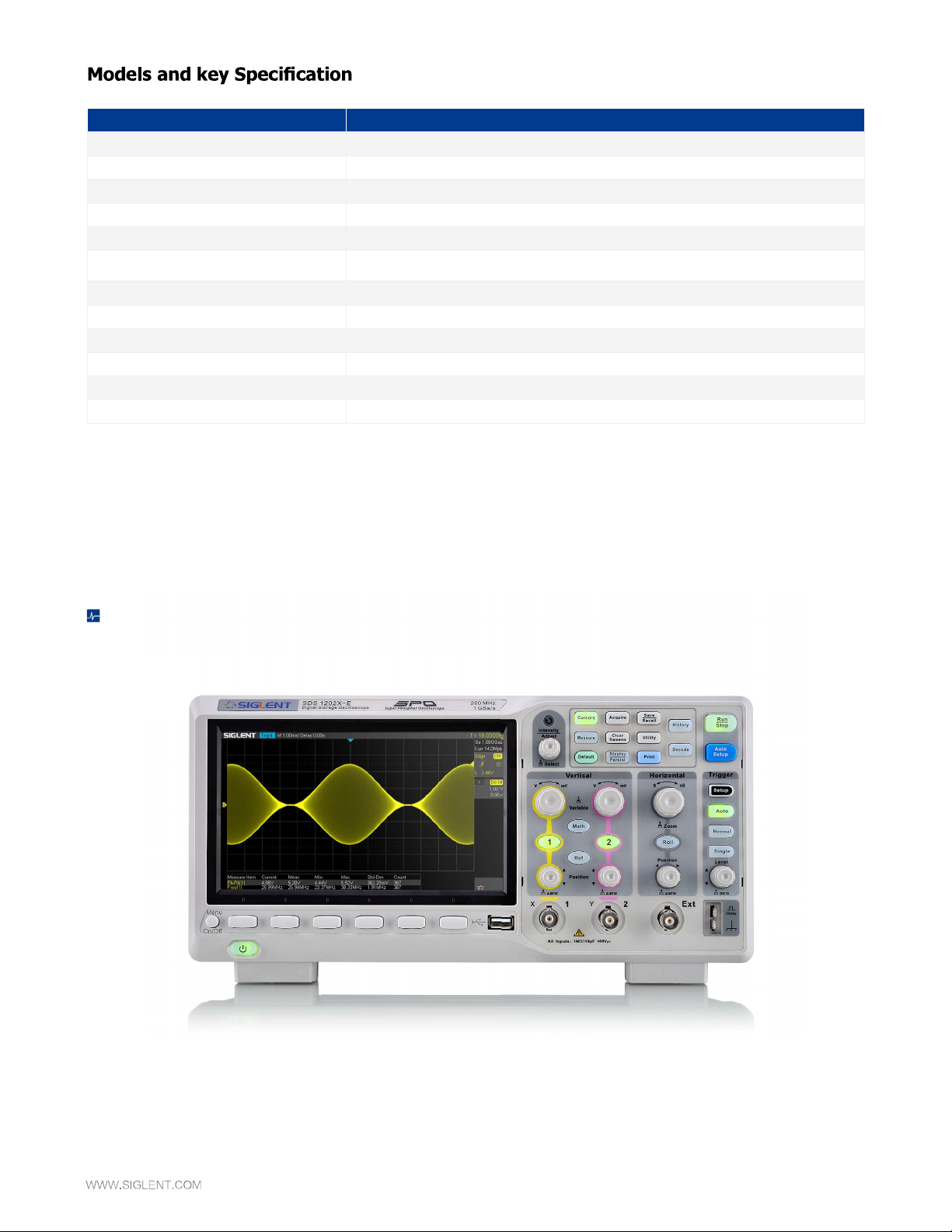
Functions & Characteristics
7 Inch TFT-LCD Display and 10 One-button Menus
• 7-inch TFT-LCD display with 800 * 480 resolution
• Most commonly used functions are accessible using 10 different one-button operation keys: Auto Setup, Default, Cursor, Measure, Roll, History, Persist, Clear
Sweep, Zoom, Print
Page 4
Functions & Characteristics
SDS1000X-E Series Digital Oscilloscope
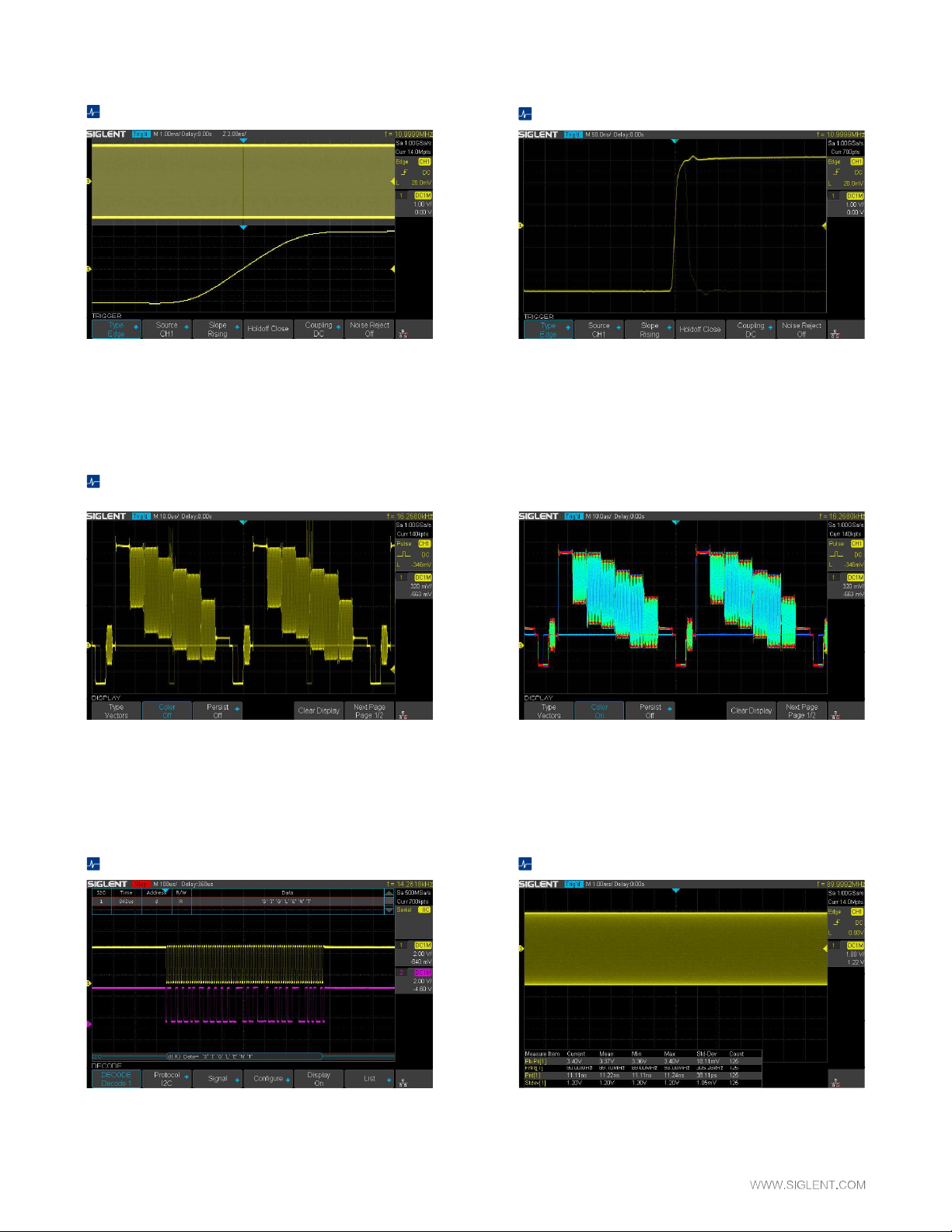
Record Length of Up to 14 Mpts
Using hardware-based Zoom technologies and a record length of up to
14 Mpts, users are able to use a higher sampling rate to capture more of
the signal and then quickly zoom in to focus on the area of interest.
256-Level Intensity Grading and Color Temperature Display
Waveform Capture Rate Up to 400,000 wfm/s
With a waveform capture rate of up to 400,000 wfm/s (sequence mode),
the oscilloscope can easily capture the unusual or low-probability events.
SPO display technology delivers fast refresh rates. The resulting intensity-
graded traces are brighter where events occur more frequently and less
bright where they occur less often.
Serial Bus Decoding Function (Standard)
SDS1000X-E displays the decoding through the events list. Bus protocol
information can be quickly and intuitively displayed in a tabular format.
The color temperature display is similar to the intensity-graded trace in
function, except that the trace occurrence is represented by different
colors (color “temperature”) as opposed to changes in the intensity of
one color. Red represents the most common occurrences or probabilities,
while blue is used to mark points that occur least frequently.
True Measurement to 14 Mpoints
At any one timebase, the SDS1000X-E can measure using all 14M sample
points. This ensures the accuracy of measurements while the math co-
processor decreases measurement time and increases ease-of-use.
Page 5
SDS1000X-E Series Digital Oscilloscope
History Waveforms (History) Mode and
Segmented Acquisition (Sequence)
Pl ay bac k t he lat es t t r ig gered event s u si n g the his t ory f unc ti o n.
Segmented memory zcquisition will store the waveform into multiple
(up to 80,000) memo ry segments, each se gment will store trigge red
waveforms and timestamp each frame.
1 Mpoints FFT
Gate and Zoom Measurement
Through Gate and Zoom measurement, the user can specify an arbitrary
int erval of w ave form data analy sis and st atist ic s. Th is he lp s avoid
measurement errors that can be caused by invalid or extraneous data,
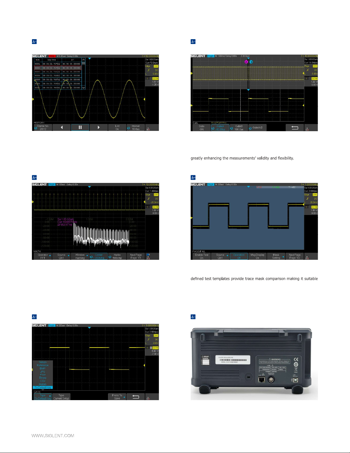
High Speed Hardware-Based Pass/Fail Function
The new math co-process or enables FFT analysis of incoming signals
using up to 1M samples per waveform. This provides high frequency
resolution with a fast refresh rate. The FFT function also supports a
variety of window functions so that it can adapt to different spectrum
measurement needs.
The SDS1000X-E utilizes a hardware-based Pass/Fail function, performing
up to 40,000 Pass / Fail decisions each second. Easily generate user-
for long-term signal monitoring or automated production line testing.
Customizable Default Key Complete Connectivity
The current parameters of oscilloscope can be preset to Default Key
through the Save menu.
SDS1000X-E supports USB Host, USB Device (USB-TMC), LAN (VXI-11),
Pass/Fail and Trigger Out
Page 6

Acquire System
Sampling Rate 1 GSa/s (Single - Channel), 500 MSa/s (Dual - Channel)
Memory Depth Max 14 Mpts/Ch (Single - Channel , 7 Mpts/Ch (Dual - Channel)
Peak Detect 1 nsec
Average Averages: 4, 16, 32, 64, 128, 256, 512, 1024
Eres Enhance bits: 0.5, 1.5, 2, 2.5, 3; Selectable
Waveform interpolation Sinx/x, Linear
Input
Channels 2 Analog
Coupling DC, AC, GND
Impedance
Max. Input voltage
CH to CH Isolation DC~ Max BW >40 dB
Probe attenuator 0.1X, 0.2X, 0.5X, 1X, 2X, 5X, 10X…… 1000X, 2000X, 5000X, 10000X
SDS1000X-E Series Digital Oscilloscope
Vertical System
Bandwidth -3dB 200 MHz
Vertical Resolution 8 bit
Vertical Scale Probe 1X
Offset Range Probe 1X
Bandwidth Limit
Bandwidth Flatness
Low Frequency Response
(AC -3dB)
Noise
SFDR including harmonics
DC Gain Accuracy
Offset Accuracy
Risetime Typical 1.8 ns
Overshoot (500 ps Pulse)
Page 7

SDS1000X-E Series Digital Oscilloscope
Horizontal System
Timebase Scale 1.0 ns/div - 100 s/div
Channel Skew
Waveform Capture Rate Up to 100,000 wfm/s (normal mode), 400,000 wfm/s (sequence mode)
Intensity grading 256 Levels
Display Format Y-T X-Y Roll
Timebase Accuracy
Roll Mode 50 ms/div - 100 s/div (1-2-5 step)
Trigger System
Trigger Mode Auto, Normal, Single
Trigger Level
Holdoff Range 80 ns - 1.5 s
AC
Trigger Coupling
Coupling Frequency Response
(CH1 CH2)
Coupling Frequency Response
(EXT)
DC
LFRJ
HFRJ
Noise RJ (CH1 - CH2)
DC: Passes all components of the signal
AC: Blocks DC components and attenuates signals below 8 Hz
LFRJ: Blocks the DC component and attenuates the low-frequency
components below 2 MHz
HFRJ: Attenuates the high-frequency components above 1.2 MHz
DC: Passes all components of the signal
AC: Blocks DC components and attenuates signals below 30 Hz
LFRJ: Blocks the DC component and attenuates the low-frequency
components below 10 KHz
HFRJ: Attenuates the high-frequency components above 500 KHz
Trigger Accuracy (Typical)
CH1 - CH2: DC - Max BW 0.6 div
Trigger Sensitivity
Trigger Jitter
Trigger Displacement
Edge Trigger
Slope Rising, Falling, Rising & Falling
Source CH1/CH2/EXT/(EXT/5)/AC Line
Slope Trigger
Slope Rising, Falling
Limit Range , , ,
Source CH1/CH2
Time Range 2 ns - 4.2 s
Resolution 1 ns
EXT: 200 mVpp DC - 10 MHz
300 mVpp 10 MHz - BW frequency
EXT/5: 1 Vpp DC - 10 MHz
1.5 Vpp 10 MHz - BW frequency
Delay Trigger: 0 to 10,000 div
Page 8

Pulse Trigger
Polarity +wid , -wid
Limit Range , , ,
Source CH1 / CH2
Pulse Range 2 ns - 4.2 s
Resolution 1 ns
Video Trigger
Signal Standard NTSC PAL 720p/50 720p/60 1080p/50 1080p/60 1080i/50
1080i/60 Custom
Source CH1 / CH2
Sync Any, Select
Trigger condition Line, Field
Window Trigger
Window Type Absolute, Relative
Source CH1 / CH2
Interval Trigger
Slope Rising, Falling
Limit Range , , ,
Source CH1/CH2
Time Range 2 ns - 4.2 s
Resolution 1ns
Dropout Trigger
Timeout Type Edge, State
Source CH1 / CH2
Slope Rising, Falling
Time Range 2ns - 4.2s
Resolution 1 ns
Runt Trigger
Polarity +wid , -wid
Limit Range , , ,
Source CH1 / CH2
Time Range 2 ns - 4.2 s
Resolution 1 ns
Pattern Trigger
Pattern Setting Invalid, Low, High
Logic AND, OR, NAND, NOR
Source CH1 / CH2
Limit Range , , ,
Time Range 2 ns - 4.2 s
Resolution 1 ns
SDS1000X-E Series Digital Oscilloscope
Page 9

SDS1000X-E Series Digital Oscilloscope
Serial Trigger
I2C Trigger
Condition Start, Stop, Restart, No Ack, EEPROM, 7 bits Address & Data, 10 bits Address & Data, Data Length
Source (SDA/SCL) CH1, CH2
Data format Hex
Limit Range
Data Length
R/W bit Addr & Data: Read, Write, Do not care
SPI Trigger
Condition Data
Source (CS/CL/Data) CH1, CH2
Data format Binary
Data Length 4 - 96 bit
Bit Value 0, 1, X
Bit Order LSB, MSB
UART/ RS232 Trigger
Condition Start, Stop, Data, Parity Error
Source (RX/TX) CH1, CH2
Data format Hex
Limit Range
Data Length 1 byte
Data Width 5 bit, 6 bit, 7 bit, 8 bit
Parity Check None, Odd, Even
Stop Bit 1 bit, 1.5 bit, 2 bit
Idle Level High, Low
Baud(Selectable) 600/1200/2400/4800/960019200/38400/57600/115200 bit/s
(Custom) 300 bit/s - 334000 bit/s
CAN Trigger
Condition All, Remote, ID, ID + Data, Error
Source CH 1, CH 2
ID STD (11 bit), EXT (29 bit)
Data Format Hex
Data Length 1 - 2 byte
Baud Rate (Selectable) 5k/10k/20k/50k/100k/125k/250k/500k/800k/1M bit/s
Baud Rate (Custom) 5 kbit/s - 1 Mbit/s
LIN Trigger
Condition Break, Frame ID, ID+Data, Error
Source CH1, CH2
ID 1 byte
Data Format Hex
Data Length 1 - 2 byte
Baud Rate (Selectable) 600/1200/2400/4800/9600/19200 bit/s
Baud Rate (Custom) 300 bit/s - 20 kbit/s
EEPROM: 1 byte
Addr & Data: 1 - 2 byte
Data Length: 1 - 12 byte
Page 10

Serial Decoder
I2C Decoder
Signal SCL, SDA
Address 7 bits, 10 bits
Threshold -4.5 - 4.5 div
List 1 - 7 lines
SPI Decoder
Signal SCL, MISO, MOSI, CS
Edge Select Rising, Falling
Idle Level Low, High
Bit Order MSB, LSB
Threshold -4.5 - 4.5 div
List 1 - 7 lines
UART/ RS232 Decoder
Signal RX, TX
Data Width 5 bit 6 bit 7 bit 8 bit
Parity Check None, Odd, Even
Stop Bit 1 bit, 1.5 bit, 2 bit
Idle Level Low, High
Threshold -4.5 - 4.5 div
List 1 - 7 lines
CAN Decoder
Signal CAN_H, CAN_L
Source CAN_H, CAN_L, CAN_H-CAN_L
Threshold -4.5 - 4.5 div
List 1 - 7 lines
LIN Decoder
Ver1.3, Ver2.0
Threshold -4.5 - 4.5 div
List 1 - 7 lines
SDS1000X-E Series Digital Oscilloscope
Page 11

SDS1000X-E Series Digital Oscilloscope
Measurement
Source CH1, CH2, Math, Ref, History
Number of Measurements Display 5 measurements at the same time
Measurement Range Screen region, Gate region
Measurement Parameters ( 38 Types )
Max Highest value in input waveform
Min Lowest value in input waveform
Pk-Pk Difference between maximum and minimum data values
Ampl Difference between top and base in a bimodal signal, or between max and min in an unimodal signal
Top Value of most probable higher state in a bimodal waveform
Base Value of most probable lower state in a bimodal waveform
Mean Average of all data values
Cmean
Vertical Voltage
Horizontal Time
Delay Phase Calculate the phase difference between two edges
Cursors
Statistics Current, Mean, Min, Max, Stdev, Count
Counter Hardware 6 bit counter channels are selectable
Stdev Standard deviation of all data values
Cstd
VRMS Root mean square of all data values
Crms
FOV Overshoot after a falling edge; (base-min)/Amplitude
FPRE Overshoot before a falling edge; (max-top)/Amplitude
ROV Overshoot after a rising edge; (max-top)/Amplitude
RPRE Overshoot before a rising edge; (base-min)/Amplitude
Level@X the voltage value of the trigger point
Period
Freq
+Wid
-Wid
Rise Time
Fall Time
Bwid
crossing
+Dut Ratio of positive width to period
-Dut Ratio of negative width to period
Delay
Time@Level
FRR
FRF
FFR
FFF
LRR
LRF
LFR
LFF
Skew Time of source A edge minus time of nearest source B edge
Track: Time X1, X2, (X1-X2)
Page 12

Math Function
Operation
FFT window Rectangular, Blackman, Hanning, Hamming
FFT display Full Screen, Split
Number of Decoders 2
I/O
Standard USB Host, USB Device, LAN, Pass/Fail, Trigger Out
Pass/Fail 3.3 V TTL Output
Display (Screen)
Display Type 7-inch TFT LCD
Display Resolution 800×480
Display Color 24 bit
Contrast (Typical) 500:1
Backlight 300 nit
Range 8 x 14 divisions
Display (Waveform)
Display Mode Dot, Vector
Persist Time
Color Display Normal, Color
Screen Saver 1 min, 5 min, 10 min, 30 min, 1 hour, Off
Language
SDS1000X-E Series Digital Oscilloscope
Environments
Temperature Operating: 10 - +40
Non-operating: -20 - +60
Humidity , 24 hours
, 24 hours
Height
Electromagnetic Compatibility 2004/108/EC)
Execution Standard EN 61326-1:2006
EN 61000-3-2:2006 + A2:2009, EN 61000-3-3:2008
Safety 2006 / 95 / EC
Execution Standard EN 61010-1:2010/EN 61010-2-030:2010
Power Supply
Input Voltage 100 - 240 VAC, CAT II, Auto selection
Frequency 50 / 60 / 400 Hz
Power 25 W Max
Mechanical
Length: 312 mm
Dimensions
Weight N.W: 2.5 Kg; G.W: 3.5 Kg
Width: 134 mm
Height: 150 mm
Page 13

SDS1000X-E Series Digital Oscilloscope
Probes and Accessories
Probe Picture Model Description
Bandwidth: 70 MHz, 1 X/10 X, 1 M/10 Mohm, 300 V/600 V
Passive
Current Probe
Bandwidth: 100 MHz, 1 X/10 X, 1 M/10 Mohm,300 V/600 V
Bandwidth: 200 MHz, 1 X/10 X, 1 M/10 Mohm, 300 V/600 V
Bandwidth: 100 KHz, Max. continuous current: 20 Arms, Peak current: 60 A
CP4020
CP4050
CP4070
CP4070A Bandwidth: 300 KHz, Max. continuous current: 70 Arms, Peak current: 200 A
CP5030
Bandwidth: 1 MHz, Max. continuous current: 50 Arms, Peak current: 140 A
Switch Ratio: 500 mV/A, 50 mV/A
battery source
Bandwidth: 150 KHz, Max. continuous current: 70 Arms, Peak current: 200 A
Bandwidth: 50 MHz, Max. continuous current: 30 Arms, Peak current: 50 A
CP5030A
CP5150
CP5500
Differential Probe DPB4080
Bandwidth: 100 MHz, Max. continuous current: 30 Arms, Peak current: 50 A
Bandwidth: 12 MHz, Max. continuous current: 150 Arms, Peak current: 300 A
Bandwidth: 5 MHz, Max. continuous current: 500 Arms, Peak current: 750A
Bandwidth: 50 MHz, Differential Range: 800 V (DC + Peak AC),
Page 14

Probe Picture Model Description
SDS1000X-E Series Digital Oscilloscope
Differential Probe
High Voltage
DPB5150
DPB5150A
DPB5700
DPB5700A
HPB4010
Bandwidth: 70 MHz, Differential Range: 1500 V (DC + Peak AC), 50 X/500 X
Bandwidth: 100 MHz, Differential Range: 1500 V (DC + Peak AC),
Bandwidth: 70 MHz, Differential Range: 7000 V (DC + Peak AC),
DC 5 V/1 A USB adapter
Bandwidth: 100 MHz
Differential Range: 7000 V (DC + Peak AC),
100 X/1000 X
DC 5 V/1 A USB adapter
Bandwidth: 40 MHz
Differential Range: DC 10 KV, AC (rms): 7 KV (sine), AC (Vpp): 20 KV (Pulse)
1000 X
Isolated front end ISFE
Demo Board STB-3
The USB Device interface allows a connection into the GPIB interface. USB-
GPIB adapter allows the oscilloscope to easily send and receive commands
IEEE488.2 standard.
Output signals include square waves, sine, AM, fast edge , pulse, PWM, I2C,
CAN, LIN etc. Used in teaching and demonstrations.
Page 15

SDS1000X-E Series Digital Oscilloscope
Ordering information
Product Name
Standard Accessories
Optional Accessories
SDS1000X-E Series Digital Oscilloscope
SDS1202X-E 200 MHz Two Channels
USB Cable -1
Quick Start -1
Passive Probe -2
Power Cord -1
CD (Included User Manual and EasyScopeX software)-1
Isolated Front End ISFE
STB Demo Source STB-3
High Voltage Probe HPB4010
CP4020/CP4050/CP4070/
Current Probe
Differential Probe
CP4070A/CP5030/CP5030A/
CP5150/CP5500
DPB4080/DPB5150/DPB5150A
/DPB5700/DPB5700A
 Loading...