

Page 1
User Manual
SDS1000X-E Series Digital
oscilloscope
UM0101X-E02B
SIGLENT TECHNOLOGIES CO., LTD.
Page 2

Page 3

SIGLENT
Copyright and Declaration
Copyright
SIGLENT TECHNOLOGIES CO., LTD. All Rights Reserved.
Trademark Information
SIGLENT is the registered trademark of SIGLENT TECHNOLOGIES CO., LTD.
Declaration
SIGLENT products are protected by patent law in and outside of P.R.C.
SIGLENT reserves the right to modify or change parts of or all the specifications or pricing
policies at company’s sole decision.
Information in this publication replaces all previously corresponding material.
Any way of copying, extracting or translating the contents of this manual is not allowed
without the permission of SIGLENT.
Product Certification
SIGLENT guarantees this product conforms to the national and industrial stands in China
and other international stands conformance certification is in progress.
Contact Us
If you have any problem or requirement when using our products, please contact
SIGLENT TECHNOLOGIES CO., LTD
Add:3//F, Bldg No.4, Antongda Industrial Zone, 3rd Liuxian Road, Bao’an District,
Shenzhen, 518101, P.R.China
Tel:400-878-0807
E-mail:sales@siglent.com
http://www.siglent.com
User Manual I
Page 4

SIGLENT
Safety Information
General Safety Summary
Carefully read the following safety precautions to avoid any personal injury or
damage to the instrument and any products connected to it. To avoid potential
hazards, please use the instrument as specified.
Use Proper Power Line
Only the power cord designed for the instrument and authorized by local country could be
used.
Ground the Instrument
The instrument is grounded through the protective earth conductor of the power line. To
avoid electric shock, please make sure the instrument is grounded correctly before
connecting its input or output terminals.
Connect the Signal Wire Correctly
The potential of the signal wire is equal to the earth, so do not connect the signal wire to a
high voltage.
Look Over All Terminals‟ Ratings
To avoid fire or electric shock, please look over all ratings and sign instruction of the
instrument. Before connecting the instrument, please read the manual carefully to gain
more information about the ratings.
Use Proper Overvoltage Protection
Make sure that no overvoltage (such as that caused by a thunderstorm) can reach the
product, or else the operator might expose to danger of electrical shock.
Electrostatic Prevention
Operate in an electrostatic discharge protective area environment to avoid damages
induced by static discharge. Always ground both the internal and external conductors of
the cable to release static before connecting.
Keep Well Ventilation
Inadequate ventilation may cause increasing of temperature, which will eventually
damage the instrument. So keep well ventilation and inspect the intake and fan regularly.
Avoid Circuit or Components Exposed
Do not touch exposed contacts or components when the power is on.
II User Manual
Page 5

SIGLENT
Use proper Fuse
Use only the specified fuse.
Do Not Operate Without Covers
Do not operate the instrument with covers or panels removed.
Do Not Operate With Suspected Failures.
If you suspect damage occurs to the instrument, have it inspected by qualified service
personnel before further operations. Any maintenance, adjustment or replacement
especially to circuits or accessories must be performed by SIGLENT authorized
personnel.
Do Not Operate in Wet Conditions.
In order to avoid short circuiting to the interior of the device or electric shock, please do
not operate in a humid environment.
Do Not Operate in an Explosive Atmosphere.
In order to avoid damages to the device or personal injuries, it is important to operate the
device away from an explosive atmosphere.
Keep Product Surfaces Clean and Dry.
To avoid the influence of dust and/or moisture in air, please keep the surface of device
clean and dry.
Handling Safety
Please handle with care during transportation to avoid damages to buttons, knob
interfaces and other parts on the panels.
User Manual III
Page 6
SIGLENT
Terms in this Manual. These terms may appear in this manual:
WARNING
Warning statements indicate the conditions or practices that could
result in injury or loss of life.
CAUTION
Caution statements indicate the conditions or practices that could
result in damage to this product or other property.
Safety Terms and Symbols
Terms on the product. These terms may appear on the product:
DANGER Indicates direct injuries or hazards that may happen.
WARNING Indicates potential injuries or hazards that may happen.
CAUTION Indicates potential damages to the instrument or other property that may
happen.
Symbols on the product. These symbols may appear on the product:
Hazardous protective Earth Warning Test Power Switch
Voltage Terminal Ground
IV User Manual
Page 7

SIGLENT
Measurement Category
Measurement Categories
The oscilloscopes can make measurements in measurement category I.
WARNING
This oscilloscope can only be used for measurements within its specified
measurement categories.
Measurement Category Definitions
Measurement category I is for measurements performed on circuits not directly connected
to MAINS. Examples are measurements on circuits not derived from MAINS, and
specially protected (internal) MAINS derived circuits. In the latter case, transient stresses
are variable; for that reason, the transient withstand capability of the equipment is made
known to the user.
Measurement category II is for measurements performed on circuits directly connected to
the low voltage installation. Examples are measurements on household appliances,
portable tools and similar equipment.
Measurement category III is for measurements performed in the building installation.
Examples are measurements on distribution boards, circuit-breakers, wiring, including
cables, bus-bars, junction boxes, switches, socket-outlets in the fixed installation, and
equipment for industrial use and some other equipment, for example. Stationary motors
with permanent connection to the fixed installation.
Measurement category IV is for measurements performed at the source of the low-voltage
installation. Examples are electricity meters and measurements on primary over current
protection devices and ripple control units.
User Manual V
Page 8
SIGLENT
Working Environment
Temperature
Operating: 10℃ to +40℃
Non-operation:-20℃ to +70℃
Humidity
Under +35℃:≤90% relative humidity
+35℃ to +40℃: ≤60% relative humidity
WARNING
To avoid short circuit inside the instrument or electric shock, please do not
operate in humid environment.
Altitude
Operating: less than 3 Km
Non-operation: less than 15 Km
Installation (overvoltage) Category
This product is powered by mains conforming to installation (overvoltage) category II.
WARNING
Make sure that no overvoltage (such as that caused by thunderbolt) can reach
the product, or else the operator might expose to danger of electric shock.
Installation (overvoltage) Category Definitions
Installation (overvoltage) category I refers to signal level which is applicable to equipment
measurement terminals connected to the source circuit. In these terminals, precautions
are done to limit the transient voltage to the corresponding low level.
Installation (overvoltage) category II refers to the local power distribution level which is
applicable to equipment connected to the AC line (AC power).
VI User Manual
Page 9

SIGLENT
Ventilation Requirement
This oscilloscope uses fan to force cooling. Please make sure that the air intake and
exhaust areas are free from obstructions and have free air. When using the oscilloscope
in a bench-top or rack setting, provide at least 10 cm clearance beside, above and behind
the instrument for adequate ventilation.
WARNING
Inadequate ventilation may cause temperature increase which would damage
the instrument. So please keep the instrument well ventilated during operation
and inspect the intake and fan regularly.
User Manual VII
Page 10

SIGLENT
General Care and Cleaning
Care
Do not store or leave the instrument in direct sunshine for long periods of time.
WARNING
To avoid damages to the instrument or probe, please do not leave them in fog,
liquid, or solvent.
Cleaning
Please perform the following steps to clean the instrument and probe regularly according
to its operating conditions.
1. Disconnect the instrument from all power sources, and then clean it with a soft wet
cloth.
2. Clean the loose dust on the outside of the instrument and probe with a soft cloth.
When cleaning the LCD, take care to avoid scarifying it.
WARNING
To avoid damages to the surface of the instrument and probe, please do not
use any corrosive liquid or chemical cleanser.
WARNING
Make sure that the instrument is completely dry before restarting it to avoid
short circuits or personal injuries.
VIII User Manual
Page 11

Document Overview
Quick Start
Provide information about preparations before
using the instrument and a brief introduction of
the instrument.
To Set the Vertical System
Introduce the functions of the vertical system of
the oscilloscope.
To Set the Horizontal System
Introduce the functions of the horizontal system
of the oscilloscope.
To Set the Sample System
Introduce the functions of the sample system of
the oscilloscope.
To Trigger the Oscilloscope
Introduce the trigger mode, trigger coupling,
trigger hold off, external trigger and various
trigger types of the oscilloscope.
Serial Trigger
Introduce how to trigger the input signal.
To Save Reference Waveform
Introduce how to save and display REF
waveform.
To Make Math Operation
Introduce the math operation function of the
oscilloscope.
To Make Cursor Measurements
Introduce how to use cursors to make
measurements.
To Make Measurements
Introduce how to use measure function to
measure the waveform parameters.
Display Setting
Introduce how to set the display of the
oscilloscope.
Save and Recall
Introduce how to save and recall the
measurement result and the setting of the
oscilloscope.
System Setting
Introduce how to set the system setup.
Default
Introduce the Default setup of the oscilloscope
Troubleshooting
Introduce how to deal with common failures of
the oscilloscope.
This manual introduces how to use the digital oscilloscope in details.
SIGLENT
User Manual IX
Page 12

SIGLENT
Content Conventions in this Manual:
This manual takes SDS1202X-E for example and the descriptions here have contained all
the functions and performances of other models.
Table of Content
Copyright and Declaration ............................................................................................................. I
Safety Information .......................................................................................................................... II
General Safety Summary ........................................................................................................... II
Safety Terms and Symbols ....................................................................................................... IV
Measurement Category ........................................................................................................... V
Working Environment ............................................................................................................. VI
X User Manual
Page 13

SIGLENT
Ventilation Requirement ........................................................................................................ VII
General Care and Cleaning .................................................................................................... VIII
Document Overview ...................................................................................................................... IX
Quick Start ....................................................................................................................................... 1
General Inspection .................................................................................................................... 2
Appearance and Dimensions .................................................................................................... 3
To Prepare the Oscilloscope for Use ......................................................................................... 4
To Adjust the Supporting Legs ...................................................................................... 4
To Connect to Power Supply ........................................................................................ 5
Power-on Inspection ...................................................................................................... 6
To Connect the Probe .................................................................................................... 6
Function Inspection ........................................................................................................ 7
Probe Compensation ..................................................................................................... 8
Front Panel Overview .................................................................................................... 9
Rear Panel Overview ................................................................................................... 10
Front Panel Function Overview ............................................................................................... 11
Horizontal ....................................................................................................................... 11
Vertical ........................................................................................................................... 12
Trigger ............................................................................................................................ 13
Run Control ................................................................................................................... 14
Universal Knob .............................................................................................................. 15
Menu ............................................................................................................................... 16
Help ......................................................................................................................................... 17
User Interface .......................................................................................................................... 18
To Use the Security Lock ......................................................................................................... 20
To Set the Vertical System ......................................................................................................... 21
To Enable the Channel ............................................................................................................. 22
To Adjust the Vertical Scale ..................................................................................................... 23
To Adjust the Vertical Position ................................................................................................ 23
To Specify Channel Coupling ................................................................................................... 24
To Specify Bandwidth Limit ..................................................................................................... 24
To Specify Probe Attenuation Factor ....................................................................................... 25
To Specify channel Input Impedance ...................................................................................... 25
To Specify Amplitude Unit ....................................................................................................... 26
To Specify Deskew ................................................................................................................... 26
To Invert a Waveform .............................................................................................................. 26
Set the Horizontal System .......................................................................................................... 27
Adjust the Horizontal Scale ..................................................................................................... 28
Adjust Trigger Delay ................................................................................................................ 29
Set the Roll mode .................................................................................................................... 30
Use the Zoom Function ........................................................................................................... 31
To Set the Sample System ......................................................................................................... 32
Run Control ............................................................................................................................. 33
Overview of Sampling ............................................................................................................. 34
User Manual XI
Page 14

SIGLENT
Sampling Theory........................................................................................................... 34
Sample Rate.................................................................................................................. 35
Oscilloscope Bandwidth and Sample Rate .............................................................. 36
Select Memory Depth ............................................................................................................. 37
Select Sampling Mode ............................................................................................................. 38
Select Waveform Interpolation Method ................................................................................. 39
Select Acquisition Mode ......................................................................................................... 41
Normal ............................................................................................................................ 41
Peak Detect ..................................................................................................................... 42
Average............................................................................................................................ 43
High Resolution ............................................................................................................... 44
Change the Horizontal Format ................................................................................................ 45
Use Sequence Mode ............................................................................................................... 46
To Trigger the Oscilloscope ........................................................................................................ 48
Trigger Source ......................................................................................................................... 50
Trigger Mode ........................................................................................................................... 51
Trigger Level ............................................................................................................................ 52
Trigger Coupling ...................................................................................................................... 53
Trigger Holdoff ........................................................................................................................ 54
Noise Rejection ....................................................................................................................... 55
Trigger Type ............................................................................................................................. 57
Edge Trigger .................................................................................................................. 58
Slope Trigger ................................................................................................................. 59
Pulse Trigger ................................................................................................................. 61
Video Trigger ................................................................................................................. 63
Window Trigger ............................................................................................................. 66
Interval Trigger .............................................................................................................. 69
DropOut Trigger ............................................................................................................ 71
Runt Trigger ................................................................................................................... 73
Pattern Trigger .............................................................................................................. 75
Serial trigger and decode ............................................................................................................ 77
I2C Trigger and Serial Decode ................................................................................................. 78
Setup for I2C Signals ........................................................................................................ 78
I2C Triggering................................................................................................................... 80
I2C Serial Decode ............................................................................................................ 84
SPI Triggering and Serial Decode ..................................................................................................... 86
Setup for SPI Signals ................................................................................................... 86
SPI Triggering ............................................................................................................... 89
SPI Serial Decode ........................................................................................................ 91
UART/RS232 Triggering and Serial Decode ..................................................................................... 93
Setup for UART/RS232 Signals ................................................................................. 93
UART/RS232 Triggering.................................................................................................... 95
UART/RS232 Serial Decode ............................................................................................. 97
CAN Trigger and Serial Decode ............................................................................................... 99
XII User Manual
Page 15

SIGLENT
Setup for CAN Signals ...................................................................................................... 99
CAN Triggering ............................................................................................................... 101
CAN Serial Decode......................................................................................................... 103
LIN Triggering and Serial Decode .......................................................................................... 105
Setup for LIN Signals ................................................................................................. 105
LIN Triggering ................................................................................................................ 106
LIN Serial Decode .......................................................................................................... 108
To Save Reference Waveform.................................................................................................. 110
To Save REF Waveform to Internal Memory ......................................................................... 111
To Display REF Waveform ...................................................................................................... 111
To Adjust REF Waveform Display ........................................................................................... 112
To Clear REF Waveform Display ............................................................................................. 112
To Make Math Operation ........................................................................................................... 113
Units for Math Waveforms .................................................................................................... 113
Math Operators ..................................................................................................................... 114
Addition or Subtraction ................................................................................................. 114
Multiplication and Division ........................................................................................... 115
FFT Operation ................................................................................................................ 116
Math Function Operation ...................................................................................................... 119
Differentiate .................................................................................................................. 119
Integrate ........................................................................................................................ 120
Square Root ................................................................................................................... 121
To Make Cursors Measurements ............................................................................................. 122
X Cursors ............................................................................................................................... 122
Y Cursors ................................................................................................................................ 122
To Make Cursor Measurements ............................................................................................ 123
To Make Measurements ................................................................................................................ 124
Type of Measurement ........................................................................................................... 125
Voltage Measurements ................................................................................................. 125
Time Measurements ..................................................................................................... 127
Delay Measurements .................................................................................................... 128
To Make Automatic Measurement ........................................................................................ 129
To Clear Measurement Parameters ....................................................................................... 131
To Make All Measurement .................................................................................................... 131
Display Setting ............................................................................................................................... 132
To Set Display Type ................................................................................................................ 133
To Set Color Display ............................................................................................................... 134
To Set and Clear Persistence ................................................................................................. 134
To clear the display ................................................................................................................ 135
To Select Grid Type ................................................................................................................ 136
To Adjust Waveform Intensity ............................................................................................... 136
To Adjust Grid Brightness ...................................................................................................... 137
To Adjust Transparence ......................................................................................................... 137
Save and Recall .............................................................................................................................. 138
User Manual XIII
Page 16

SIGLENT
Save Type ............................................................................................................................... 139
Internal Save and Recall ........................................................................................................ 141
External save and recall ......................................................................................................... 142
Disk Management ................................................................................................................. 145
To Create a New File or Folder ...................................................................................... 146
To delete a file or folder ................................................................................................ 147
System Function Setting ................................................................................................................ 148
To View the System Status .................................................................................................... 149
To Do Self Calibration ............................................................................................................ 150
To Enable or Disable the Sound ............................................................................................ 151
To Specify the Language ........................................................................................................ 151
To Do Pass/Fail Test ............................................................................................................... 152
To Set and Perform Pass/Fail Test .................................................................................. 153
To Save and Recall Test Mask ........................................................................................ 154
IO Set ..................................................................................................................................... 156
To Set the USB Device ................................................................................................... 156
To Set the LAN ............................................................................................................... 157
To Set Aux Output ......................................................................................................... 158
To Update Firmware and Configuration ................................................................................ 159
Do Self Test ............................................................................................................................ 160
Screen Test .................................................................................................................... 160
Keyboard Test ................................................................................................................ 161
LED Test ......................................................................................................................... 162
To specify Screen Saver Time ................................................................................................ 163
To Use the History Function .......................................................................................................... 164
Factory Setup ................................................................................................................................ 166
Troubleshooting ............................................................................................................................ 170
Content of Figure
Figure 1 Front View ................................................................................................................... 3
XIV User Manual
Page 17

SIGLENT
Figure 2 Top View ..................................................................................................................... 3
Figure 3 Adjust the Supporting Legs ......................................................................................... 4
Figure 4 To Connect to Power Supply ....................................................................................... 5
Figure 5 Function Inspection ..................................................................................................... 7
Figure 6 Front Panel Overview .................................................................................................. 9
Figure 7 Rear panel Overview ................................................................................................. 10
Figure 8 Help Message ............................................................................................................ 17
Figure 9 User Interface ............................................................................................................ 18
Figure 10 To Use the Security Lock ......................................................................................... 20
Figure 11 Display Type Set to Dots .......................................................................................... 39
Figure 12 x Interpolation ......................................................................................................... 40
Figure 13 Sinx/x Interpolation ................................................................................................. 40
Figure 14 Acquisition System .................................................................................................. 41
Figure 15 Pulse With 0.1% Duty, Normal Mode ..................................................................... 42
Figure 16 Pulse With 0.1% Duty, Peak Detect Mode .............................................................. 42
Figure 17 With Random Noise, Normal Mode ........................................................................ 43
Figure 18 With Random Noise, Average Mode ....................................................................... 44
Figure 19 SEQUENCE Function Menu ..................................................................................... 46
Figure 20 HISTORY Function Menu ......................................................................................... 46
Figure 21 Turn off the Noise Reject ......................................................................................... 55
Figure 22 Turn on the Noise Reject ......................................................................................... 56
Figure 23 Edge Trigger ............................................................................................................. 58
Figure 24 Slope Trigger ............................................................................................................ 60
Figure 25 Pulse Trigger ............................................................................................................ 62
Figure 26 Video Trigger ........................................................................................................... 65
Figure 27 Absolute Window Trigger ........................................................................................ 67
Figure 28 Relative Window Trigger ......................................................................................... 68
Figure 29 Interval Trigger ........................................................................................................ 70
Figure 30 Edge DropOut Trigger .............................................................................................. 72
Figure 31 State DropOut Trigger ............................................................................................. 73
Figure 32 Runt Trigger ............................................................................................................. 74
Figure 33 Pattern Trigger ......................................................................................................... 76
Figure 34 I2C SINGAL Menu .................................................................................................... 78
Figure 35 I2C Decode Menu .................................................................................................... 84
Figure 36 SINGAL Menu .......................................................................................................... 86
Figure 37 CLK Menu ................................................................................................................ 87
Figure 38 MISO Menu ............................................................................................................. 87
Figure 39 MOSI Menu ............................................................................................................. 87
Figure 40 SPI TRIG SET Menu .................................................................................................. 89
Figure 41 UART SIGNAL Menu ................................................................................................ 93
Figure 42 Reference Waveform ............................................................................................. 112
Figure 43 FFT Waveform In Split Mode ................................................................................. 118
Figure 44 Differential Function Operation ............................................................................ 119
Figure 45 Integral without Offset .......................................................................................... 120
User Manual XV
Page 18

SIGLENT
Figure 46 Integral with Offset ............................................................................................... 121
Figure 47 Square Root ........................................................................................................... 121
Figure 48 Measure Pulse Width ............................................................................................ 123
Figure 49 Voltage Measurements ......................................................................................... 125
Figure 50 Overshoot .............................................................................................................. 126
Figure 51 Preshoot ................................................................................................................ 126
Figure 52 Time Measurements ............................................................................................. 127
Figure 53 Select the Measurement Parameter ..................................................................... 129
Figure 54 Added the Measurement ...................................................................................... 130
Figure 55 All Parameters Measurement ............................................................................... 131
Figure 56 Vectors Display ...................................................................................................... 133
Figure 57 Dots Display ........................................................................................................... 133
Figure 58 Color Temperature ................................................................................................ 134
Figure 59 Persist Set to Infinite ............................................................................................. 135
Figure 60 SAVE/RECALL File System ...................................................................................... 142
Figure 61 Select Save Location .............................................................................................. 143
Figure 62 File Name Dialogue ............................................................................................... 143
Figure 63 Input Keyboard ...................................................................................................... 146
Figure 64 System Status ........................................................................................................ 149
Figure 65 Do Self Cal ............................................................................................................. 150
Figure 66 Pass/Fail Test ......................................................................................................... 152
Figure 67 LAN Setting Interface ............................................................................................ 157
Figure 68 Screen Test ............................................................................................................ 160
Figure 69 Keyboard Test ........................................................................................................ 161
Figure 70 LED Test ................................................................................................................. 162
Figure 71 Screen Saver Interface .......................................................................................... 163
Figure 72 History ................................................................................................................... 164
XVI User Manual
Page 19

SIGLENT
Quick Start
This chapter introduces the preparations when using the oscilloscope for the first time, the
front panel, rear panel and user interface of the oscilloscope,
The contents of this chapter:
General Inspection
Appearance and Dimensions
To Prepare the Oscilloscope for Use
Front Panel Overview
Rear Panel Overview
Front Panel Function Overview
Back Panel Function Overview
User Interface
To Use the Security Lock
User Manual 1
Page 20

SIGLENT
General Inspection
1. Inspect the shipping container for damage.
Keep the damaged shipping container or cushioning material until the contents of the
shipment have been checked for completeness and the instrument has passed both
electrical and mechanical tests.
The consigner or carrier shall be liable for the damage to instrument resulting from
shipment. SIGLENT would not be responsible for free maintenance/rework or
replacement of the unit.
2. Inspect the instrument.
In case of any damage, or defect, or failure, notify your SIGLENT sales
representative.
3. Check the Accessories
Please check the accessories according to the packing lists. If the accessories are
incomplete or damaged, please contact your SIGLENT sales representative.
2 User Manual
Page 21
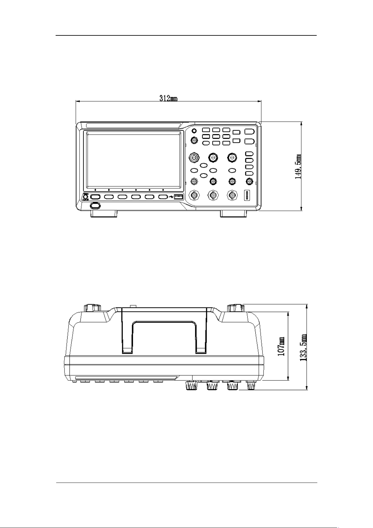
Appearance and Dimensions
SIGLENT
Figure 1 Front View
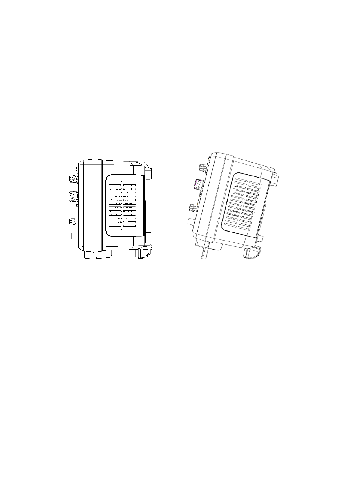
Figure 2 Top View
User Manual 3
Page 22
SIGLENT
To Prepare the Oscilloscope for Use
To Adjust the Supporting Legs
Adjust the supporting legs properly to use them as stands to tilt the oscilloscope upwards
for stable placement of the oscilloscope as well as better operation and observation.
Figure 3 Adjust the Supporting Legs
4 User Manual
Page 23
SIGLENT
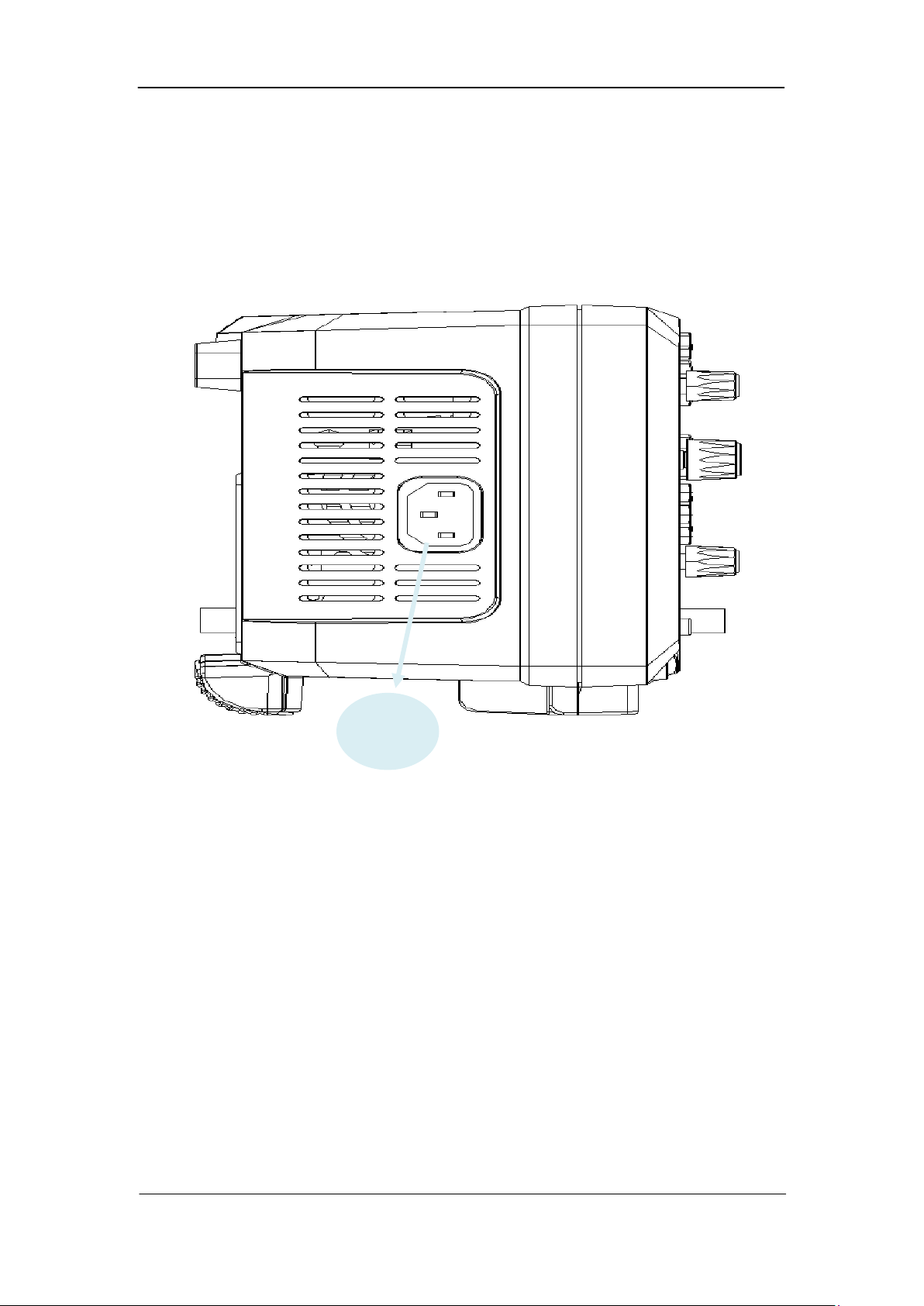
Power
socket
To Connect to Power Supply
The power requirements of the oscilloscope are 100-240 V, 50/60/440 Hz. Please use
the power cord supplied with the accessories to connect the oscilloscope to the power
source.
Figure 4 To Connect to Power Supply
User Manual 5
Page 24

SIGLENT
Power-on Inspection
When the oscilloscope is energized, press the power key at the lower-left corner of the
front panel to start the oscilloscope. During the start-up process, the oscilloscope
performs a series of self-tests and you can hear the sound of relay switching. After the
self-test is finished, the welcome screen is displayed.
To Connect the Probe
SIGLENT provides passive probes for the oscilloscopes. For detailed technical
information of the probes, please refer to the corresponding Probe User’s Guide.
Connect the Probe:
1. Connect the BNC terminal of the probe to a channel BNC connector of the
oscilloscope at the front panel.
2. Connect the probe tip to the circuit point to be tested and connect the ground alligator
clip of the probe to the circuit ground terminal.
6 User Manual
Page 25
SIGLENT
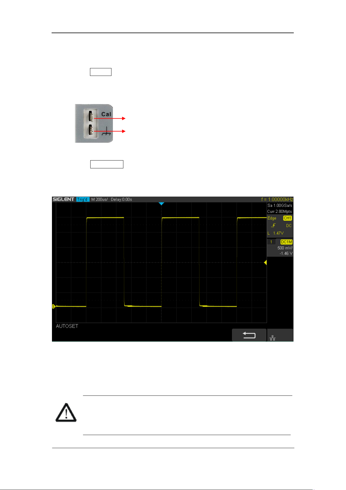
Function Inspection
1. Press the Default button on the front panel to restore the instrument to its default
configuration.
2. Connect the ground alligator clip of the probe to the “Ground Terminal” under the
probe compensation signal output terminal.
Compensation Signal Output Terminal
Ground Terminal
3. Use the probe to connect the input terminal of CH1 of the oscilloscope and the
“Compensation Signal Output Terminal” of the probe.
4. Press the Auto Setup.
5. Observe the waveform on the display. In normal condition, the display should be a
square waveform as shown in the figure below:
Figure 5 Function Inspection
6. Use the same method to test the other channels. If the square waveforms actually
shown do not match that in the figure above, please perform “Probe Compensation”
in the next section.
WARNING
To avoid electric shock during the use of probe, please make sure that the
insulated wire of the probe is in good condition and do not touch the metallic
part of the probe when the probe is connected to high voltage source
User Manual 7
Page 26

SIGLENT
Probe Compensation
When the probes are used for the first time, you should compensate the probes to match
the input channels of the oscilloscope. Non-compensated or poorly compensated probes
may cause measurement inaccuracy or error. The probe compensation procedures are as
follows.
1. Set the switch to 10X on the probe.
2. Perform steps 1, 2, 3 and 4 of “Function Inspection” in the previous section.
3. Check the waveforms displayed and compare them with the following:
Over Perfectly Under
Compensated Compensated Compensated
4. Use a nonmetallic driver to adjust the low-frequency compensation adjustment hole
on the probe until the waveform displayed is as the “Perfectly compensated” in the
figure above.
8 User Manual
Page 27
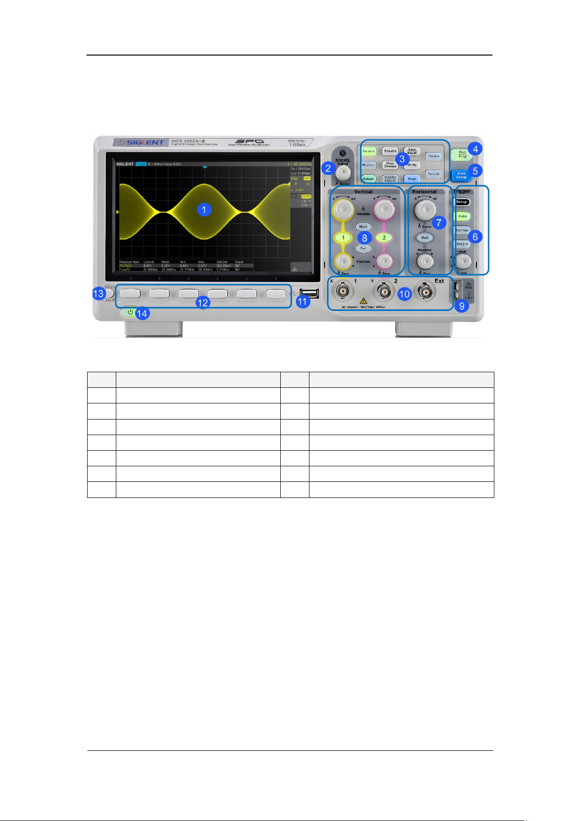
Front Panel Overview
NO.
Description
NO.
Description
1
LCD Display
8
Vertical Control
2
Universal Knob
9
Probe Comp
3
Common Function Menus
10
Analog Channel and Ext Input
4
Run/Stop
11
USB Host
5
Auto Setup
12
Menu Softkey
6
Trigger Control
13
Menu on/off
7
Horizontal Control
14
Power Button
SIGLENT
Figure 6 Front Panel Overview
User Manual 9
Page 28
SIGLENT
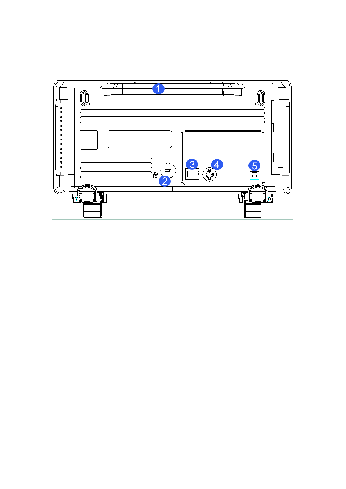
Rear Panel Overview
Figure 7 Rear panel Overview
1. Handle
Pull up the handle vertically for easy carrying of the instrument. When you do not need
the handle, press it down.
2. Safety lock Hole
You can lock the instrument to a fixed location using the security lock (please buy it
yourself) via the lock hole.
3. LAN
The instrument can be connected to network via this interface to perform remote
control.
4. Pass/Fail or Trigger Out
The BNC port can output a signal that reflects the current waveform capture rate of
the oscilloscope at each trigger or a pass/fail test pulse.
5. USB Device
The oscilloscope support SCPI remote control commands, user can control the
oscilloscope through this interface.
10 User Manual
Page 29
SIGLENT
Front Panel Function Overview
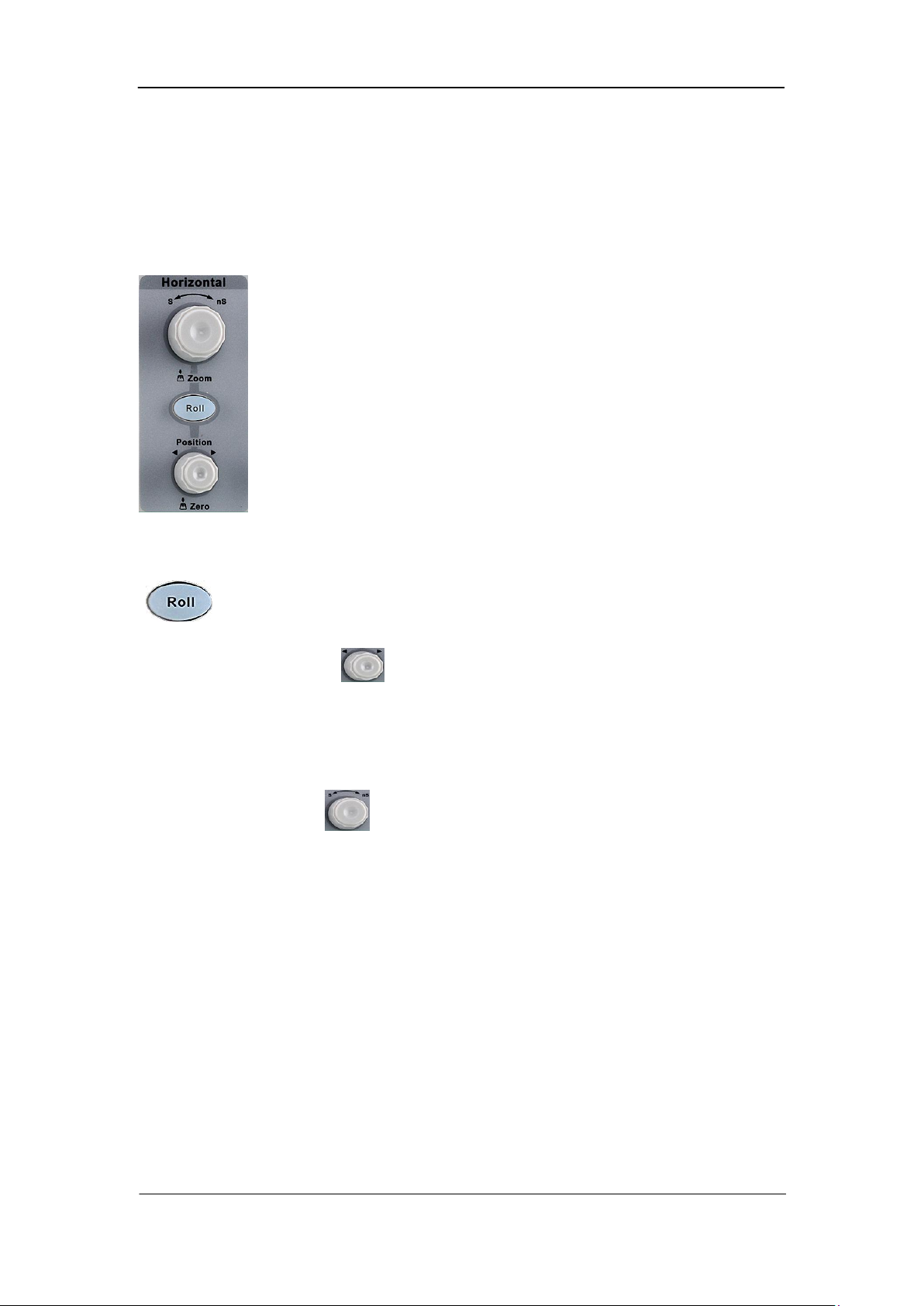
Horizontal
: Quickly enter the roll mode. The timebase range is from 50mS/div to
100S/div.
Horizontal Position Knob : adjust horizontal position. The trigger point would
move left or right relative to the center of the screen when you turn the knob. During the
modification, waveforms of all the channels would move left or right and the trigger
position message at the upper-right corner of the screen would change accordingly. Press
down this knob to quickly reset the trigger delay to Zero.
Horizontal Scale Knob : adjust the horizontal time base. Turn clockwise to
reduce the time base and turn counterclockwise to increase the time base. During the
modification, waveforms of all the channels will be displayed in expanded or compressed
mode and the time base message at the upper-left side of the screen would change
accordingly. Press down this knob to quickly turn on Zoom function.
User Manual 11
Page 30
SIGLENT
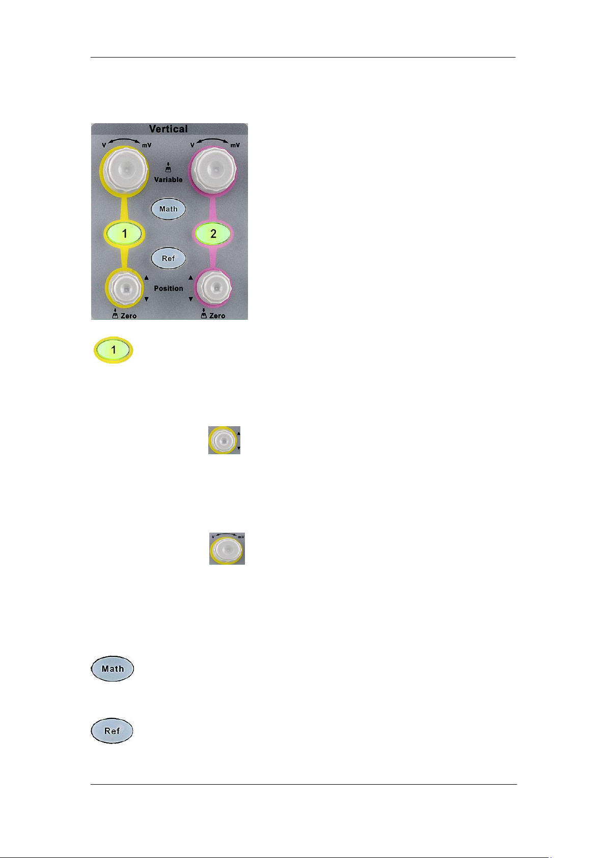
Vertical
: Analog input channels. The two channels are marked by different colors which
are also used to mark both the corresponding waveforms on the screen and
the channel input connectors. Press any key to open the corresponding
channel menu and press again to turn off the channel.
Vertical Position Knob : adjust the vertical position of the current channel
waveform. Turn clockwise to increase the position and turn counterclockwise to decrease.
During the modification, the waveform would move up and down and the position
message at the lower-left corner of the screen would change accordingly. Press down this
knob to quickly reset the vertical position to zero.
Vertical Variable Knob : adjust the vertical scale of the current channel. Turn
clockwise to decrease the scale and turn counterclockwise to increase. During the
modification, the amplitude of the waveform would enlarge or reduce and the scale
information at the right side of the screen would change accordingly. Press down this knob
to quickly switch the vertical scale adjustment modes between “Coarse” and “Fine”.
: press the button to enter the MATH function menu. The oscilloscope provides
addition, subtraction, multiplication, FFT, differential, integral and square root
operations.
: press the button to enter the REF function menu. A reference waveform can
be displayed and compared against other waveforms.
12 User Manual
Page 31

SIGLENT
Trigger
: press the button to enter the TRIGGER function menu. The oscilloscope
provides
abundant advanced trigger functions
: press the button to set the trigger mode to Auto.
: press the button to set the trigger mode to Normal.
: press the button to set the trigger mode to Single.
Trigger Level Knob : adjust the trigger level. Turn clockwise to increase the
level and turn counterclockwise to reduce the level. During the modification, the trigger
level line would move up and down and the value in the trigger level message box at the
up-right corner of the screen would change accordingly. Press down the knob to quickly
reset the trigger level to center of the waveform.
User Manual 13
Page 32

SIGLENT
Run Control
: press this key to enable the waveform auto setting function. The
oscilloscope will automatically adjust the vertical scale, horizontal time base
and trigger mode according to the input signal to realize optimum waveform
display.
: press the button to set the acquisition state to Run or Stop.
In RUN state, the key is illuminated in yellow.
In STOP state, the key is illuminated in red.
14 User Manual
Page 33

SIGLENT
Universal Knob
1. Adjust the waveform intensity.
You can press the Display/Persist button; press the Next Page softkey to go to the
second page of the DISPLAY function menu; press the Intensity softkey and then
turn the Universal Knob to adjust the waveform intensity.
2. Select the desired submenu.
In menu operation, press any menu softkey and turn the Universal Knob to select the
desired submenu under the menu and push down the knob to confirm the current
submenu. Turn clockwise to up the intensity and counterclockwise to down.
3. Modify parameters.
After having chosen a parameter, turn the Universal Knob to modify the value. Turn
clockwise to increase the intensity and counterclockwise to reduce. In addition, it can
also be used to adjust scale and offset of MATH and REF.
4. Choose file or directory or input filename.
After having entered the file system, turn the Universal Knob to select the desired file
or directory. When inputting filename, turn the Universal Knob to select the desired
character and the push the knob to confirm.
User Manual 15
Page 34

SIGLENT
Menu
: Press the button to enter the CURSOR function menu. The oscilloscope
provides manual and track cursor mode.
: Press the button to enter the DISPLAY function menu and quickly enable the
persist function. User can set the grid, intensity, graticule, transparence.
: Press the button to enter the UTILITY function menu to look at the system
status, do self calibration, set the sound, language and so on.
: The button is a shortcut key for clear function. When the measurement
statistics is ON, press the button to clear the count and recount it. When
persist is enabled, press the button to clear persist.
: Press the button to enter the MEASURE function menu to set the
measurement parameters, all measurement, statistics and set the gate.
: Press the button to enter the ACQUIRE function menu to set the acquisition
mode, memory depth, wave interpolation and so on.
: Press the button to enter the SAVE/RECALL function menu to save setups,
waveforms, pictures, or CSV files to internal memory or USB flash driver.
: Press the button to reset the oscilloscope to user default setup.
: Press the button to enter the history mode. In history mode, it can record
most 80000 frames waveforms. If sequence function is enabled, it only record
the frames which you set, the most you can set is 80000.
: Press the button to enter the DECODE function menu. The oscilloscope
supports I2C, SPI, UART/RS232, CAN and LIN serial bus decode.
: Press the button to turn off or turn on the menu.
16 User Manual
Page 35

SIGLENT
Help
The oscilloscope has an on line help function that supplies multi-language help
information.
You can access the help function by pressing any button for 2 seconds and a help window
will explain the function. Also all of the submenus include help information.
Figure 8 Help Message
User Manual 17
Page 36

SIGLENT
User Interface
Figure 9 User Interface
1. Product Logo
SIGLENT is the registered trademark of SIGLENT TECHNOLOGIES CO., LTD.
2. Channel Label/Waveform
Different channels are marked by different colors and the color of the waveform
complies with the color of the channel.
3. Trigger Status
Available trigger status includes Ready, Auto, Stop, Arm, Trig’d.
4. Horizontal Time Base
Represent the time per grid on the horizontal axis on the screen.
Use the HORIZONTAL SCALE Knob to adjust the parameter. The available
range is from 2.0 ns to 50 s.
5. Trigger Position
Turn the Horizontal Position Knob to adjust the parameter. Push the knob to set the
value to 0 automatically.
6. Trigger Delay Label
Indicate the trigger delay on the waveform.
18 User Manual
Page 37

SIGLENT
7. Frequency Counter
Display the frequency value of the trigger channel.
8. Sampling Rate/ Memory Depth
Display the current sampling rate and memory depth. Sa means the current sampling
rate and Curr means the current memory depth.
9. Trigger Setup
Trigger Type : display the current trigger type. The trigger type names display
by the abbreviation when the name is too long to display.
Trigger source : display the currently trigger source. Different channels display
in different color.
Trigger condition : display the current trigger condition.
Trigger coupling : display the current trigger coupling. Available trigger coupling
mode: DC, AC, HF Reject, LF Reject.
Trigger level : display the current value of trigger level. Push the knob to
set the trigger to the 50% of the waveform amplitude automatically.
10. Channel Setup
Probe attenuation factor : display the current probe attenuation factor of the
channel. Available probe attenuation factors: 0.1X,0.2X, 0.5X, 1X, …2000X, 5000X,
10000X.
Input impedance : display the current input impedance of the channel. Input
impedance that available: 1MΩ.
Channel coupling : display the current channel coupling of the channel. Channel
coupling that available: DC, AC, and GND.
Vertical Scale : display the current vertical scale of the channel. Turn the
Vertical Scale Knob to adjust the value.
11. Trigger Level Label
Display the position of trigger level, the color is the same to the trigger channel. It can
move from +4.5div to -4.5div of the screen center.
12. I/O status
Indicate that the USB Device (USBTMC)is connected.
Indicate that the USB Host is connected.
Indicate that the LAN port is connected, Indicate it is disconnected.
13. Menu
Display the corresponding function menu of the selected button. Press the
corresponding softkey to set the oscilloscope.
User Manual 19
Page 38

SIGLENT
Security
lock hole
To Use the Security Lock
If needed, you can use the security lock (please buy it yourself) to lock the oscilloscope to
a fixed location. The method is as follows, align the lock with the lock hole and plug it into
the lock hole vertically, turn the key clockwise to lock the oscilloscope and then pull the
key out.
Figure 10 To Use the Security Lock
20 User Manual
Page 39

To Set the Vertical System
This chapter introduces how to set the vertical system of the oscilloscope.
The contents of this chapter:
To Enable the Channel
To Adjust the Vertical Scale
To Adjust the Vertical Position
To Specify Channel Coupling
To Specify Bandwidth Limit
SIGLENT
To Specify Probe Attenuation Factor
To Specify channel Input Impedance
To Specify Amplitude Unit
To Specify Deskew
To Invert a Waveform
User Manual 21
Page 40

SIGLENT
To Enable the Channel
The oscilloscope provides 2 analog input channels (CH1, CH2) and provides independent
vertical control system for each channel. As the vertical system setting methods of both
channels are the same, this chapter takes CH1 as an example to introduce the setting
method of the vertical system.
Connect a signal to the CH1 channel connector; and then press the CH1 button in the
vertical control area (VERTICAL) at the front panel to enable CH1.
The channel setting menu is displayed at the bottom of the screen and the channel label
at the right side of the screen. The information displayed in the channel label is related to
the current channel setting.
After the channel is turned on, modify the parameters such as the vertical scale, the
horizontal time base and the trigger mode according to the input signal to make the
waveform display easy to observe and measure.
Note: to turn off the channel, press the channel button twice.
22 User Manual
Page 41

SIGLENT
Volt Scale
Range of Vertical Position
500 μV/div ~ 100 mV/div
±2V
102 mV/div ~ 1 V/div
±20 V
1.02 V/div ~ 10 V/div
±200 V
To Adjust the Vertical Scale
The vertical scale can be adjusted in Coarse or Fine mode.
Coarse adjustment (take counterclockwise as an example): set the vertical scale in
1-2-5 step namely 500uV/div, 1 mV/div, 2 mV/div, 5 mV/div, 10 mV/div …10 V/div.
Fine adjustment: further adjust the vertical scale within a relatively smaller range to
improve vertical resolution. For example: 2 V/div, 1.98V/div, 1.96V/div, 1.94 V/div …1
V/div.
If the amplitude of the input waveform is a little bit greater than the full scale under the
current scale and the amplitude would be a little bit lower if the next scale is used, fine
adjustment can be used to improve the amplitude of waveform display to view signal
details.
Press the CH1 button on the front panel; then press the Adjust softkey to select the
desired mode. Turn the VERTICAL Variable Knob to adjust the vertical scale (clockwise
to reduce the scale and counterclockwise to increase).
The scale information in the channel label at the right side of the screen will change
accordingly during the adjustment. The adjustable range of the vertical scale is related to
the probe ratio currently set. By default, the probe attenuation factor is 1X and the
adjustable range of the vertical scale is from 500uV/div to 10 V/div.
Note: push the VERTICAL Variable Knob to quickly switch between Coarse and Fine
adjustments.
To Adjust the Vertical Position
Turn the VERTICAL Position Knob to adjust the vertical position of the channel
waveform. Turn the knob clockwise to increase the vertical position and the channel
waveform moves up while counterclockwise to reduce the vertical position and the
waveform moves down. Push the knob to set the vertical position of the channel waveform
to zero.
During the adjustment, the vertical position information Volts Pos displays at the bottom of
the screen. The table below shows the range of vertical position according to the volt
scale.
User Manual 23
Page 42

SIGLENT
To Specify Channel Coupling
Set the coupling mode to filter out the undesired signals. For example, the signal under
test is a square waveform with DC offset.
When the coupling mode set to DC: the DC and AC components of the signal under
test can both pass the channel.
When the coupling mode set to AC: the DC components of the signal under test are
blocked.
When the coupling mode set to GND: the DC and AC components of the signal under
test are both blocked.
Press the CH1 button on the front panel; then press the Coupling softkey and turn the
Universal Knob to select the desired coupling mode. The default setup is DC.
The current coupling mode is displayed in the channel label at the right side of the screen.
You can also press the Coupling softkey continuously to switch the coupling mode.
To Specify Bandwidth Limit
Set the bandwidth limit to reduce display noise. For example, the signal under test is a
pulse with high frequency oscillation.
When the bandwidth limit set to Full, the high frequency components of the signal
under test can pass the channel.
When the bandwidth limit set to 20M, the high frequency components that exceed 20
MHz are attenuated.
Press the CH1 button on the front panel; then press the BW Limit softkey to select Full or
20M. The default setup is Full. When bandwidth limit is enabled, the character B will be
displayed in the channel label at the right side of the screen.
SDS1000X-E has full BW with all V/div settings including 500uV/div to 2mV/div.
24 User Manual
Page 43

SIGLENT
Menu
Attenuation Factor
0.1X
0.1 : 1
0.2X
0.2 : 1
0.5X
0.5 : 1
1X
1 : 1
2X
2 : 1
…
…
5000X
5000 : 1
10000X
10000 : 1
To Specify Probe Attenuation Factor
Set the probe attenuation factor to match the type of the probe that you are using to
ensure correct vertical readouts.
Press the CH1 button on the front panel; then press the Probe softkey and turn the
Universal Knob to select the desired value and push the knob to confirm. The default
setup is 1X.
The current probe attenuation factor is displayed in the channel label at the right side of
the screen. You can also press the Probe softkey continuously to switch the probe
attenuation factor.
The table shows the probe attenuation factor
To Specify channel Input Impedance
The channel input impedance matching gives you the most accurate measurements
because reflections are minimized along the signal path.
Impedance setting to 1MΩ is for use with many passive probes and for general-
purpose measurements. The higher impedance minimizes the loading effect of the
oscilloscope on the device under test.
Press the CH1 button on the front panel; then press the Impedance softkey to select the
desired impedance.
The current channel input impedance is displayed in the channel label at the right side of
the screen.
User Manual 25
Page 44

SIGLENT
To Specify Amplitude Unit
Select the amplitude display unit for the current channel. The available units are V and A.
When the unit is changed, the unit displayed in the channel label will change accordingly.
1. Press CH1button on the front panel to enter the CH1 function menu.
2. Press the Next Page softkey to enter the second page of the CH1 function menu.
3. Press the Unit softkey to select the desired unit V or A.
The default setup is V.
To Specify Deskew
Set the current channel deskew.Adjustable phase difference between the channel, the
adjusting range of plus or minus 100 ns.
1. Press CH1button on the front panel to enter the CH1 function menu.
2. Press the Next Page softkey to enter the second page of the CH1 function menu.
3. Press the Deskew softkey. Then turn the Universal Knob to change deskew.
To Invert a Waveform
When Invert is set to On, the voltage values of the displayed waveform are inverted.
Invert affects how a channel is displayed and it keeps the trigger settings.
Inverting a channel also changes the result of any math function selected and measure
function.
1. Press CH1button on the front panel to enter the CH1 function menu.
2. Press the Next Page softkey to enter the second page of the CH1 function menu.
3. Press the Invert softkey to turn on or off the invert display.
26 User Manual
Page 45

Set the Horizontal System
This chapter introduces how to set the horizontal system of the oscilloscope.
The contents of this chapter:
Adjust the Horizontal Scale
Adjust the Trigger Delay
Set Roll Mode
Use the Zoom Function
SIGLENT
User Manual 27
Page 46

SIGLENT
Adjust the Horizontal Scale
Turn the HORIZONTAL Scale Knob on the front panel to adjust the horizontal time base.
Turn clockwise to reduce the horizontal time base and turn counterclockwise to increase.
The time base information at the upper left corner of the screen will change accordingly
during the adjustment. The range of the horizontal scale is from 1ns/div to 100s/div.
The Horizontal Scale Knob works (in the Normal time mode) while acquisitions are
running or when they are stopped. When running, adjusting the horizontal scale knob
changes the sample rate. When stopped, adjusting the horizontal scale knob lets you
zoom into acquired data.
28 User Manual
Page 47

SIGLENT
Adjust Trigger Delay
Turn the Position Knob on the front panel to adjust the trigger delay of the waveform.
During the modification, waveforms of all the channels would move left or right and the
trigger delay message at the upper-right corner of the screen would change accordingly.
Press down this knob to quickly reset the trigger delay.
Changing the delay time moves the trigger point (solid inverted triangle) horizontally and
indicates how far it is from the time reference point. These reference points are indicated
along the top of the display grid.
All events displayed left of the trigger point happened before the trigger occurred. These
events are called pre- trigger information, and they show events that led up to the trigger
point.
Everything to the right of the trigger point is called post- trigger information. The amount of
delay range (pre- trigger and post- trigger information) available depends on the time/div
selected and memory depth.
The position knob works (in the Normal time mode) while acquisitions are running or when
they are stopped. When running, adjusting the horizontal scale knob changes the sample
rate. When stopped, adjusting the horizontal scale knob lets you zoom into acquired data.
User Manual 29
Page 48

SIGLENT
Set the Roll mode
Press the Roll button to enter the roll mode.
In Roll mode the waveform moves slowly across the screen from right to left. It only
operates on time base settings of 50 ms/div and slower. If the current time base setting is
faster than the 50 ms/div limit, it will be set to 50 ms/div when Roll mode is entered.
In Roll mode there is no trigger. The fixed reference point on the screen is the right edge
of the screen and refers to the current moment in time. Events that have occurred are
scrolled to the left of the reference point. Since there is no trigger, no pre- trigger
information is available.
If you would like to stop the display in Roll mode, press the Run/Stop button. To clear the
display and restart an acquisition in Roll mode, press the Run/Stop button again.
Use Roll mode on low- frequency waveforms to yield a display much like a strip chart
recorder. It allows the waveform to roll across the display.
30 User Manual
Page 49

SIGLENT
Use the Zoom Function
Zoom is a horizontally expanded version of the normal display. You can use Zoom to
locate and horizontally expand part of the normal window for a more detailed (higherresolution) analysis of signals.
Press the HORIZONTAL Scale Knob on the front panel to turn on the zoom function, and
press the button again to turn off the function. When Zoom function is on, the display
divides in half. The top half of the display shows the normal time base window and the
bottom half displays a faster Zoom time base window.
Normal time base Zoom time base
The area of the normal display that is expanded is outlined with a box and the rest of the
normal display is ghosted. The box shows the portion of the normal sweep that is
expanded in the lower half.
To change the time base for the Zoom window, turn the Horizontal Scale Knob. The
Horizontal Scale Knob controls the size of the box. The Horizontal Position Knob sets
the left- to- right position of the zoom window. The delay value, which is the time displayed
relative to the trigger point is momentarily displayed in the upper- right corner of the
display when the Horizontal Position Knob is turned. Negative delay values indicate
you're looking at a portion of the waveform before the trigger event, and positive values
indicate you're looking at the waveform after the trigger event.
To change the time base of the normal window, turn off Zoom; then, turn the Horizontal
Scale Knob.
User Manual 31
Page 50

SIGLENT
To Set the Sample System
This chapter introduces how to use the run control and set the sampling system of the
oscilloscope.
The contents of this chapter:
Run Control
Overview of Sampling
To Specify Memory Depth
To Select Sampling Mode
Waveform Interpolation Method
32 User Manual
Page 51

SIGLENT
Run Control
Press the Run/Stop or Single button on the front panel to run or stop the sampling
system of the scope.
When the Run/Stop b is green, the oscilloscope is running, that is, acquiring data
when trigger conditions are met. To stop acquiring data, press the Run/Stop button.
When stopped, the last acquired waveform is displayed.
When the Run/Stop button is red, data acquisition is stopped. Red "Stop" is
displayed next to the trademark logo in the status line at the top of the display. To
start acquiring data, press Run/Stop.
To capture and display a single acquisition (whether the oscilloscope is running or
stopped), press Single. The Single run control lets you view single- shot events
without subsequent waveform data overwriting the display. Use Single when you
want maximum memory depth for pan and zoom.
When you press Single, the display is cleared, the trigger mode is temporarily set to
Normal (to keep the oscilloscope from auto- triggering immediately), the trigger circuitry is
armed, the Single key is illuminated, and the oscilloscope waits until a user defined
trigger condition occurs before it displays a waveform.
When the oscilloscope triggers, the single acquisition is displayed and the oscilloscope is
stopped (the Run/Stop button is illuminated in red).
Press Single again to acquire another waveform
User Manual 33
Page 52

SIGLENT
Overview of Sampling
To understand the oscilloscope's sampling and acquisition modes, it is helpful to
understand sampling theory, sample rate and oscilloscope bandwidth and sample rate.
Sampling Theory
The Nyquist sampling theorem states that for a limited bandwidth (band- limited) signal
with maximum frequency f
than twice the maximum frequency f
reconstructed without aliasing.
f
= f
MAX
= Nyquist frequency (fN) = folding frequency
S/2
, the equally spaced sampling frequency fS must be greater
MAX
, in order to have the signal be uniquely
MAX
34 User Manual
Page 53

SIGLENT
Pulse disappeared
Sample Rate
The maximum sample rate of the oscilloscope is 2GSa/s. The actual sample rate of the
oscilloscope is determined by the horizontal scale. Turn the Horizontal Scale Knob to
adjust the sample rate.
The actual sample rate is displayed in the information area at the upper- right corner of the
screen.
The influence on the waveform when the sample rate is too low:
1. Waveform Distortion: when the sample rate is too low, some waveform details are
lost and the waveform displayed is rather different from the actual signal.
2. Waveform Confusion: when the sample rate is lower than twice the actual signal
frequency (Nyquist Frequency), the frequency of the waveform rebuilt from the sample
data is lower than the actual signal frequency. The most common aliasing is the jitter
on fast edge.
3. Waveform Leakage: when the sample rate is too low, the waveform rebuilt from the
sample data does not reflect all the actual signal information.
User Manual 35
Page 54

SIGLENT
Aliased frequency
compoments
Attenuation
0dB
-3dB
Oscilloscope Bandwidth and Sample Rate
An oscilloscope's bandwidth is typically described as the lowest frequency at which input
signal sine waves are attenuated by 3 dB (- 30% amplitude error).
At the oscilloscope bandwidth, sampling theory says the required sample rate is fS = 2fBW.
However, the theory assumes there are no frequency components above f
case) and it requires a system with an ideal brick- wall frequency response.
0dB
-3dB
Attenuation
f
N fS
Frequency
However, digital signals have frequency components above the fundamental frequency
(square waves are made up of sine waves at the fundamental frequency and an infinite
number of odd harmonics), and typically, for 500 MHz bandwidths and below,
oscilloscopes have a Gaussian frequency response.
(fBW in this
MAX
fS/4 fN fS
So, in practice, an oscilloscope's sample rate should be four or more times its bandwidth:
fS = 4fBW. This way, there is less aliasing, and aliased frequency components have a
greater amount of attenuation.
36 User Manual
Frequency
Limiting oscilloscope bandwidth (fBW) to 1/4 the sample rate (fS/4)
reduces frequency components above the Nyquist frequency (fN).
Page 55

SIGLENT
Select Memory Depth
Memory depth refers to the number of waveform points that the oscilloscope can store in a
single trigger sample and it reflects the storage ability of the sample memory. The
oscilloscope provides up to 14 Mpts memory depth.
Press the Acquire button on the front panel; press the Mem Depth softkey and then turn
the Universal Knob to select the desired value and push down the knob to confirm. Press
the Mem Depth softkey continually can also select the desired value.
The actual memory depth is displayed in the information area at the upper- right corner of
the screen. Memory depth that available: 14K, 140K, 1.4M, 14M.
Since the oscilloscope has two acquisition memories, when only one channel is on, the
maximal memory depth is up to 14 Mpts.
The relation of memory depth, sample rate and waveform length fulfills the equation
below:
Memory depth = sample rate (Sa/s) × waveform length (s/div × div)
User Manual 37
Page 56

SIGLENT
Select Sampling Mode
The oscilloscope only supports real-time sample. In this mode, the oscilloscope samples
and displays waveform within a trigger event. The maximum real-time sample rate is
1GSa/s.
Press the RUN/STOP button to stop the sample, the oscilloscope will hold the last display.
At this point, you can still use the vertical control and horizontal control to pan and zoom
the waveform.
38 User Manual
Page 57

SIGLENT
Select Waveform Interpolation Method
Under real-time sampling, the oscilloscope acquires the discrete sample values of the
waveform being displayed. In general, a waveform of dots display type is very difficult to
observe. In order to increase the visibility of the signal, the digital oscilloscope usually
uses the interpolation method to display a waveform.
Interpolation method is a processing method to “connect all the sampling points”, and
using some points to calculate the whole appearance of the waveform. For real-time
sampling interpolation method is used, even if the oscilloscope in a single captures only a
small number of sampling points. The oscilloscope can use interpolation method for filling
out the gaps between points, to reconstruct an accurate waveform.
Press the Acquire button on the front panel to enter the ACQUIRE Function menu; then
press the Interpolation softkey to select Sinx/x or X.
X: In the adjacent sample points are directly connected on a straight line. This
method is only confined to rebuild on the edge of signals, such as square wave.
Sinx/x: Connecting the sampling points with curves has stronger versatility. Sinx
interpolation method uses mathematical processing to calculation results in the actual
sample interval. This method bending signal waveform, and make it produce more
realistic regular shape than pure square wave and pulse. When the sampling rate is 3
to 5 times the bandwidth of the system. Recommended Sinx/s interpolation method.
Figure 11 Display Type Set to Dots
User Manual 39
Page 58

SIGLENT
Figure 12 x Interpolation
40 User Manual
Figure 13 Sinx/x Interpolation
Page 59

SIGLENT
Select Acquisition Mode
The acquisition mode is used to control how to generate waveform points from sample
points. The oscilloscope provides the following acquisition mode: Normal, Peak Detect,
Average and High Resolution.
1. Press the Acquire button on the front panel to enter the ACQUIRE function menu;
2. Press the Acquisition softkey; then turn the Universal Knob to select the desired
acquisition mode and push down the knob to confirm. The default setup is Normal.
Normal
In this mode, the oscilloscope samples the signal at equal time interval to rebuild the
waveform. For most of the waveforms, the best display effect can be obtained using this
mode. It is the default acquisition mode.
Figure 14 Acquisition System
User Manual 41
Page 60

SIGLENT
Peak Detect
In this mode, the oscilloscope acquires the maximum and minimum values of the signal
within the sample interval to get the envelope of the signal or the narrow pulse of the
signal that might be lost. In this mode, signal confusion can be prevented but the noise
displayed would be larger.
In this mode, the oscilloscope can display all the pulses with pulse widths at least as wide
as the sample period.
Figure 15 Pulse With 0.1% Duty, Normal Mode
Figure 16 Pulse With 0.1% Duty, Peak Detect Mode
42 User Manual
Page 61

SIGLENT
Average
In this mode, the oscilloscope averages the waveforms from multiple samples to reduce
the random noise of the input signal and improve the vertical resolution. The greater the
number of averages is, the lower the noise will be and the higher the vertical resolution will
be but the slower the response of the displayed waveform to the waveform changes will
be.
The available range of averages is from 4 to 1024 and the default is 16. When Average
mode is selected, press Averages and turn the universal knob or press the softkey
continually to set the desired average time.
Figure 17 With Random Noise, Normal Mode
User Manual 43
Page 62

SIGLENT
Figure 18 With Random Noise, Average Mode
High Resolution
This mode uses a kind of ultra-sample technique to average the neighboring points of the
sample waveform to reduce the random noise on the input signal and generate much
smoother waveforms on the screen. This is generally used when the sample rate of the
digital converter is higher than the storage rate of the acquisition memory.
High Resolution mode can be used on both single- shot and repetitive signals and it does
not slow waveform update. This mode limits the oscilloscope's real- time bandwidth
because it effectively acts like a low- pass filter.
Note: “Average” and “High Res” modes use different averaging methods. The former uses
“Waveform Average” and the latter uses “Dot Average”.
44 User Manual
Page 63

SIGLENT
Change the Horizontal Format
Press the Acquire button on the front panel; then press the XY soft key to set the XY(On)
or YT(Off) mode. The default setup is YT.
YT
It is the normal viewing mode for the oscilloscope. In the Normal time mode, signal events
occurring before the trigger are plotted to the left of the trigger point and signal events
after the trigger plotted to the right of the trigger point.
XY
XY mode changes the display from a volt- versus- time display to a volt- versus- volt
display. Channel 1 amplitude is plotted on the X- axis and Channel 2 amplitude is plotted
on the Y- axis, the two channels will be turned on or off together.
You can use XY mode to compare frequency and phase relationships between two
signals. XY mode can also be used with transducers to display strain versus displacement,
flow versus pressure, volts versus current, or voltage versus frequency.
The phase deviation between two signals with the same frequency can be easily
measured via Lissajous method. The figure below shows the measurement schematic
diagram of the phase deviation
According to sinθ=A/B or C/D (wherein, θ is the phase deviation angle between the two
channels and the definitions of A, B, C and D are as shown in the figure above), the phase
deviation angle is obtained, that is: θ=±arcsin (A/B) or ±arcsin (C/D)
If the principal axis of the ellipse is within quadrant I and III, the phase deviation angle
obtained should be within quadrant I and IV, namely within (0 to π/2) or (3π/2 to 2π). If the
principal axis of the ellipse is within quadrant II and IV, the phase deviation angle obtained
should be within quadrant II and III, namely within (π/2 to π) or (π to 3π/2).
X-Y function can be used to measure the phase deviation occurred when the signal under
test passes through a circuit network. Connect the oscilloscope to the circuit to monitor the
input and output signals of the circuit.
User Manual 45
Page 64

SIGLENT
Use Sequence Mode
Sequence is also a kind of acquisition mode, which does not display waveform during
sampling process. It improves the waveform capture rate, and the maximal capture rate is
more than 400,000 wfs/s. So it can capture the small probability event effectively.
The oscilloscope runs and fills a memory segment for each trigger event. The oscilloscope
is busy acquiring multiple segments. The oscilloscope continues to trigger until memory is
filled, and then display the waveforms on the screen.
To use the sequence mode, the HORIZONTAL Format must be set to YT.
Do the following steps to use the sequence mode.
1. Press the Acquire button on the front panel to enter the ACQUIRE function menu;
2. Press the Sequence softkey to enter the SEQUENCE function menu.
Figure 19 SEQUENCE Function Menu
3. Press the Segments Set softkey; and then turn the Universal Knob to select the
desired value.
Do the following steps to replay the sequence waveform under history mode:
1. Press the History softkey to enable HISTORY function .
Figure 20 HISTORY Function Menu
2. Press the List softkey to turn on the list display. The list records the acquisition time of
every frame and shows the frame number that displaying on the screen.
3. Press the Frame No. softkey; and then turn the Universal Knob to select the frame to
display.
46 User Manual
Page 65

SIGLENT
4. Press the softkey to replay the waveform from the current frame to 1.
5. Press the softkey to stop replay.
6. Press the softkey to replay the waveform from the current frame to the last
frame.
User Manual 47
Page 66

SIGLENT
Pre-trigger Buffer
Post-trigger Buffer
To Trigger the Oscilloscope
For trigger, you set certain trigger condition according to the requirement and when a
waveform in the waveform stream meets this condition, the oscilloscope captures this
waveform as well as the neighboring part and displays them on the screen. For digital
oscilloscope, it displays waveform continuously no matter whether it is stably triggered,
but only stable trigger can ensures stable display. The trigger circuit ensures that every
time base sweep or acquisition starts from the input signal and the user-defined trigger
condition, namely every sweep is synchronous to the acquisition and the waveforms
acquired overlap to display stable waveform.
The following is the schematic diagram of the acquisition memory. As shown in the figure
below, the position of the trigger event is determined by the reference time point and the
delay setting.
Trigger Event
↓
Acquisition Memory
Trigger setting should be based on the features of the input signal, thus you need to have
some knowledge of the signal under test to quickly capture the desired waveform.
The oscilloscope provides abundant advanced trigger functions which can help you to
focus on the desired waveform details. These trigger types are edge, slope, pulse, video,
window, interval, dropout, runt, pattern and serial trigger. This chapter will mainly introduce
all these trigger functions which mentioned above in details and tell you how to set the
trigger conditions to capture desired waveform.
48 User Manual
Page 67

The contents of this chapter:
Trigger Source
Trigger Mode
Trigger Level
Trigger Coupling
Trigger Holdoff
Noise Rejection
Trigger Type
Edge Trigger
Slope Trigger
SIGLENT
Pulse Trigger
Video Trigger
Window Trigger
Interval trigger
DropOut Trigger
Runt Trigger
Pattern Trigger
User Manual 49
Page 68

SIGLENT
Note: to select stable channel waveform as the trigger source to stabilize the display.
Trigger Source
The oscilloscope’s trigger source includes analog channels (CH1, CH2), EXT, EXT/5 and
AC Line.
Press the Setup button on the front panel to enter the TRIGGER function menu; press the
Source softkey and then turn the Universal Knob to select the desired trigger source.
The current trigger source is displayed at the upper right corner of the screen. Select
channel with signal input as trigger source to obtain stable trigger.
Analog channel input:
Signals input from analog channels CH1 and CH2 can all be used as the trigger source.
No matter whether the input of the channel selected is enabled, the channel can work
normally.
External trigger input:
External trigger source can be used to connect external trigger signal to the EXT TRIG
channel when all of the four channels are sampling data. The trigger signal (such as
external clock and signal of the circuit to be tested) will be connected to EXT and EXT/5
trigger source via the [EXT TRIG] connector. EXT/5 trigger source attenuates the signal
by a factor of 5. It extends the trigger level. You can set the trigger condition within the
range of trigger level (-8 div to +8 div).
AC line:
The trigger signal is obtained from the AC power input of the oscilloscope. This kind of
signals can be used to display the relationship between signal (such as illuminating device)
and power (power supply device). For example, it is mainly used in related measurement
of the power industry to stably trigger the waveform output from the transformer of a
transformer substation.
50 User Manual
Page 69

SIGLENT
Trigger Mode
The oscilloscope’s trigger mode includes auto, normal and single. Trigger mode affects
the way in which the oscilloscope searches for the trigger
After the oscilloscope starts running, the oscilloscope operates by first filling the
pre-trigger buffer. It starts searching for a trigger after the pre-trigger buffer is filled and
continues to flow data through this buffer while it searches for the trigger. While searching
for the trigger, the oscilloscope overflows the pre-trigger buffer and the first data put into
the buffer is first pushed out (First Input First Out, FIFO).
When a trigger is found, the pre- trigger buffer contains the events that occurred just
before the trigger. Then, the oscilloscope fills the post- trigger buffer and displays the
acquisition memory.
Press the Auto, Normal and the Single buttons on the front panel to select the desired
trigger mode, and the corresponding status light will be lighted.
In the Auto trigger mode (the default setting), if the specified trigger conditions are
not found, triggers are forced and acquisitions are made so hat signal activity is
displayed on the oscilloscope.
The Auto trigger mode is appropriate when:
Checking DC signals or signals with unknown levels or activity.
When trigger conditions occur often enough that forced triggers are
unnecessary.
In the Normal trigger mode, triggers and acquisitions only occur when the specified
trigger conditions are found. Otherwise, the oscilloscope holds the original waveform
and waits for the next trigger.
The Normal trigger mode is appropriate when:
You only want to acquire specific events specified by the trigger settings.
Triggering on an infrequent signal from a serial bus (for example, I2C, SPI, CAN,
LIN, etc.) or another signal that arrives in bursts. The Normal trigger mode lets
you stabilize the display by preventing the oscilloscope from auto- triggering.
In the Single trigger mode, the oscilloscope waits for a trigger and displays the
waveform when the trigger condition is met and then stops.
The Single trigger mode is appropriate when:
To capture single event or aperiodic signal.
To capture burst or other unusual signals.
User Manual 51
Page 70

SIGLENT
Trigger Level
Trigger level and slope define the trigger point,
Positive Slope
Negative Slope
Trigger Level
Trigger Point Trigger Point
Input Signal
You can adjust the trigger level for a selected analog channel by turning the Trigger Level
Knob.
You can push the Trigger Level Knob to set the level to the waveform's 50% value
immediately. If AC coupling is used, pushing the Trigger Level knob sets the trigger level
to about 0 V.
The position of the trigger level for the analog channel is indicated by the trigger level icon
(If the analog channel is on) at the left side of the display. The value of the analog
channel trigger level is displayed in the upper- right corner of the display.
52 User Manual
Page 71

SIGLENT
Note: trigger coupling has nothing to do with the channel coupling.
Trigger Coupling
Press the Setup button on the front panel to enter the TRIGGER function menu, and then
press the Coupling softkey and turn the Universal Knob or press the Coupling softkey
continually to select the desired coupling mode.
The oscilloscope provides 4 kinds of trigger coupling modes:
DC: allow DC and AC components into the trigger path.
AC: block all the DC components and attenuate signals lower than 5.8 Hz. Use AC
coupling to get a stable edge trigger when your waveform has a large DC offset.
LF Reject: block the DC components and reject the low frequency components lower
than 2.08MHz. Low frequency reject removes any unwanted low frequency
components from a trigger waveform, such as power line frequencies, etc., that can
interfere with proper triggering. Use LF Reject coupling to get a stable edge trigger
when your waveform has low frequency noise.
HF Reject: reject the high frequency components higher 1.27MHz)
User Manual 53
Page 72

SIGLENT
Note: adjust the time scale and horizontal position will not affect the holdoff time.
Trigger Holdoff
Trigger holdoff can be used to stably trigger the complex waveforms (such as pulse
series). Holdoff time is the amount of time that the oscilloscope waits before re-arming the
trigger circuitry. The oscilloscope will not trigger until the holdoff time expires.
Use the holdoff to trigger on repetitive waveforms that have multiple edges (or other
events) between waveform repetitions. You can also use holdoff to trigger on the first
edge of a burst when you know the minimum time between bursts.
For example, to get a stable trigger on the repetitive pulse burst shown below, set the
holdoff time to be >200 ns but <600 ns.
Holdoff
200ns 600ns
Trigger Point
The correct holdoff setting is typically slightly less than one repetition of the waveform. Set
the holdoff to this time to generate a unique trigger point for a repetitive waveform. Only
edge trigger and serial trigger have holdoff option. The holdoff time of the oscilloscope is
adjustable from 100ns to 1.5s.
1. Press the Stop button, and then use the Horizontal Position Knob and the
Horizontal Scale Knob to find where the waveform repeats. Measure this time using
cursors; then, set the holdoff.
2. Press the Setup button on the front panel to enter the TRIGGER function menu. The
default trigger type is edge.
3. Press the Holdoff Close softkey; and then turn the Universal Knob to set the desired
holdoff time.
54 User Manual
Page 73

SIGLENT
Noise Rejection
Noise Reject adds additional hysteresis to the trigger circuitry. By increasing the trigger
hysteresis band, you reduce the possibility of triggering on noise. However, this also
decreases the trigger sensitivity so that a slightly larger signal is required to trigger the
oscilloscope.
Press the Setup button on the front panel, and then press the Noise Reject softkey
continually to set the option to On or Off to turn on or off the noise rejection function.
Figure 21 Turn off the Noise Reject
User Manual 55
Page 74

SIGLENT
Figure 22 Turn on the Noise Reject
If the signal you are probing is noisy, you can set up the oscilloscope to reduce the noise
in the trigger path and on the displayed waveform. First, stabilize the displayed waveform
by removing the noise from the trigger path. Second, reduce the noise on the displayed
waveform.
1. Connect a signal to the oscilloscope and obtain a stable display.
2. Remove the noise from the trigger path by setting trigger coupling to LF Reject, HF
Reject or turning on Noise Reject.
3. Set the Acquisition option to Average to reduce noise on the displayed waveform.
56 User Manual
Page 75

SIGLENT
Trigger Type
The oscilloscope provides abundant advanced trigger functions, including various serial
bus triggers.
Edge trigger
Slope trigger
Pulse trigger
Video trigger
Window trigger
Interval trigger
DropOut trigger
Runt trigger
Pattern trigger
User Manual 57
Page 76

SIGLENT
Note: Press the Auto Setup button will set the trigger type to Edge and slope to rising.
Edge Trigger
Edge trigger distinguishes the trigger points by seeking the specified edge (rising, falling,
rising & falling) and trigger level.
Rising Edge Falling Edge
Trigger Level
Trigger Point Trigger Point
1. Press the Setup button on the front panel to enter the TRIGGER system function
menu.
2. Press the Type softkey; turn the Universal Knob to set select Edge and then push
the knob to confirm.
3. Press the Source softkey; turn the Universal Knob to select CH1, CH2, EXT, EXT/5
or AC Line as the trigger source.
4. Press the Slope softkey; turn the Universal Knob to select the desired trigger edge
(rising, falling or rising & falling), and then press down the knob to confirm. The current
trigger slope is displayed at the upper right corner of the screen.
5. Turn the Trigger Level Knob to adjust the trigger level to obtain stable trigger.
Figure 23 Edge Trigger
58 User Manual
Page 77

SIGLENT
Slope Trigger
The slope trigger looks for a rising or falling transition from one level to another level in
greater than or less than a certain amount of time.
In the oscilloscope, positive slope time is defined as the time difference between the two
crossing points of trigger level line A and B with the positive edge as shown in the figure
below.
A
The upper limit of trigger level
B The lower limit of trigger level
Positive slope time
1. Press the Setup button on the front panel to enter the TRIGGER function menu.
2. Press the Type softkey; turn the Universal Knob to set select Slop and then push the
knob to confirm.
3. Press the Source softkey; turn the Universal Knob to select CH1 or CH2 as the
trigger source.
4. Press the Slop softkey; turn the Universal Knob to set select the desired trigger edge
(rising or falling), and then push down the knob to confirm. The current trigger slope is
displayed at the upper right corner of the screen.
5. Press Lower Upper softkey to select the Lower or Upper trigger level; then turn the
Trigger Level Knob to adjust the position. The trigger level values are displayed at
the upper right corner of the screen.
The lower trigger level cannot be upper than the upper trigger level. In the trigger state
message box, L1 means the upper trigger lever while L2 means the lower trigger level.
User Manual 59
Page 78

SIGLENT
Figure 24 Slope Trigger
6. Press the Limit Range softkey; then turn the Universal Knob to select the desired
slope condition, and push down the knob to confirm.
<= (less than a time value): trigger when the positive or negative slope time of the
input signal is lower than the specified time value.
>= (greater than a time value): trigger when the positive or negative slope time of
the input signal is greater than the specified time value.
[--,--] (within a range of time value):trigger when the positive or negative slope
time of the input signal is greater than the specified lower limit of time and lower
than the specified upper limit of time value.
--][-- (outside a range of time value): trigger when the positive or negative slope
time of the input signal is greater than the specified upper limit of time and lower
than the specified lower limit of time value.
60 User Manual
Page 79

SIGLENT
Pulse Trigger
Trigger on the positive or negative pulse with a specified width.
Positive Pulse Width
Trigger Level
Negative Pulse Width
1. Press the Setup button on the front panel to enter the TRIGGER function menu.
2. Press the Type softkey; turn the Universal Knob to select Pulse and then push the
knob to confirm.
3. Press the Source softkey; turn the Universal Knob to select CH1 or CH2 as the
trigger source.
4. Turn the Trigger Level Knob to adjust the trigger level to the desired place.
5. Press the Polarity softkey to select Positive or Negative pulse that to trigger on. The
current trigger polarity is displayed at the upper right corner of the screen.
6. Press the Limit Range softkey; turn the Universal Knob to select the desired
condition.
<= (less than a time value): trigger when the positive or negative pulse time of the
input signal is lower than the specified time value.
For example, for a positive pulse, if you set t (pulse real width) < 100ns, the
waveform will trigger.
>= (greater than a time value): trigger when the positive or negative pulse time of
the input signal is greater than the specified time value.
For example, for a positive pulse, if you set t (pulse real width) >100ns, the
waveform will trigger.
User Manual 61
Page 80

SIGLENT
[--,--] (within a range of time value):trigger when the positive or negative pulse
time of the input signal is greater than the specified lower limit of time and lower
than the specified upper limit of time value.
For example, for a positive pulse, if you set t (pulse real width) >100ns and
t<300ns, the waveform will trigger.
--][-- (outside a range of time value): trigger when the positive or negative pulse
time of the input signal is greater than the specified upper limit of time and lower
than the specified lower limit of time value.
62 User Manual
Figure 25 Pulse Trigger
Page 81

SIGLENT
Standard
Type
Sync Pulse
NTSC
Interlaced
BI-level
PAL
Interlaced
BI-level
HDTV 720P/50
Progressive
Tri-level
HDTV 720P/60
Progressive
Tri-level
HDTV 1080P/50
Progressive
Tri-level
HDTV 1080P/60
Progressive
Tri-level
HDTV 1080i/50
Progressive
Tri-level
HDTV 1080i/50
Progressive
Tri-level
Custom
Frame Rate
25Hz, 30Hz, 50Hz, 60Hz
Of Lines
300~2000
Of Fields
1, 2, 3, 4
Interlace
1:1, 2:1, 4:1, 8:1
Trigger Position
Line
Field
(line value)/1
1 (line value)/2
2 (line value)/3
3 (line value)/4
4 (line value)/5
5 (line value)/6
6 (line value)/7
7 (line value)/8
8
Video Trigger
Video triggering can be used to capture the complicated waveforms of most standard
analog video signals. The trigger circuitry detects the vertical and horizontal interval of the
waveform and produces triggers based on the video trigger settings you have selected.
The oscilloscope supports standard video signal field or line of NTSC (National Television
Standards Committee), PAL (Phase Alternating Line) HDTV (High Definition Television)
and custom video signal trigger.
1. Press the Setup button on the front panel to enter the TRIGGER function menu.
2. Press the Type softkey; then turn the Universal Knob to select Video and push down
the knob to confirm.
3. Press the Source softkey; turn the Universal Knob to select CH1 or CH2 as the
trigger source. Turn the Trigger Level Knob does not change the trigger level
because the trigger level is automatically set to the sync pulse.
4. Press the Standard softkey to select the desired video standard. The oscilloscope
supports the following video standards.
The table below shows the parameters of the Custom video trigger.
User Manual 63
Page 82

SIGLENT
Of Lines
Of Fields
Interlace
Trigger Line
Trigger Field
800
1
1:1
800
1
800
1,2,4 or 8
2:1
400
1, 1~2, 1~4, 1~8
800
1,2,4 or 8
4:1
200
1, 1~2, 1~4, 1~8
800
1,2,4 or 8
8:1
100
1, 1~2, 1~4, 1~8
Standard
Field 1
Field 2
NTSC
1 to 262
1 to 263
PAL
1 to 312
1 to 313
HDTV 720P/50, HDTV 720P/60
1 to 750
HDTV 1080P/50, HDTV 1080P/60
1 to 1125
HDTV 1080iP/50, HDTV 1080i/60
1 to 562
1 to 563
The table below takes Of Lines as 800 as an example to explain the relation between
Of Lines, Of Fields, Interlace, Trigger Line and Trigger Field.
5. Press the Sync softkey to select Any or Select trigger mode.
Any: trigger on any of the horizontal sync pulses
Select: trigger on the appointed line and field you have set. Press the Line or
Field softkey; then turn the Universal Knob to set the value.
The following table lists the line numbers per field for each video standard.
The following are exercises to familiarize you with video triggering.
To trigger on a specific line of video
To use Custom video trigger
To Trigger on a Specific Line of Video
Video triggering requires greater than 1/2 division of sync amplitude with any analog
channel as the trigger source.
The example below set to trigger on field 2, line 124 using the NTSC video standard.
1. Press the Setup button on the front panel to enter the TRIGGER system function
menu.
2. Press the Type softkey; then use the Universal Knob to select Video and push down
the knob to confirm.
3. Press the Source softkey; turn the Universal Knob to select CH1 as the trigger source,
and press the knob to confirm.
4. Press the Standard softkey; turn the Universal Knob to select NTSC, and press the
knob to confirm.
5. Press the Sync softkey and set the option to Select; press the Line softkey and then
turn the universal to select 022 and push the knob to confirm; press the Field softkey
and then turn the Universal Knob to select 1 and push the knob to confirm
64 User Manual
Page 83

SIGLENT
Figure 26 Video Trigger
To Use Custom Video Trigger
Custom video trigger supports frame rate of 25Hz, 30Hz, 50Hz and 60Hz, and the line
range is available from 300 to 2000. The steps below show how to set custom trigger.
1. Press the Setup button on the front panel to enter the TRIGGER function menu.
2. Press the Type softkey; then use the Universal Knob to select Video and push down
the knob to confirm.
3. Press the Source softkey; turn the Universal Knob to select CH1 as the trigger
source, and push down the knob to confirm.
4. Press the Standard softkey; turn the Universal Knob to select Custom, and push
down the knob to confirm.
5. Press the Setting softkey to enter the custom setting function menu. Press the
Interlace softkey; turn the Universal Knob to select the desired value.
6. Press the Of Field softkey; turn the Universal Knob to select the desired value.
7. Press the Sync softkey to enter the TRIG ON menu to set the line and field.
Press the Type softkey to select Select or Any.
If the Type option set to Select, press the Line softkey; turn the Universal Knob
to select the desired value. Press the Field softkey; turn the Universal Knob to
select the desired value.
User Manual 65
Page 84

SIGLENT
Window Trigger
Windows trigger provides a high trigger level and a low trigger level. The instrument
triggers when the input signal passes through the high trigger level or the low trigger level.
There are two kinds of window types: Absolute and Relative. They have different trigger
level adjustment methods. Under Absolute window type, the lower and the upper trigger
levels can be adjusted respectively via the Level knob; under Relative window type, adjust
the Center value to set the window center; adjust the Delta value to set the window range,
the lower and the upper trigger levels always move together.
Horizontal Trigger Position
High Level
Low Level
If the lower and the upper trigger levels are both within the waveform amplitude range,
the oscilloscope will trigger on both rising and falling edge.
If the upper trigger level is within the waveform amplitude range while the lower
trigger level is out of the waveform amplitude range, the oscilloscope will trigger on
rising edge only.
If the lower trigger level is within the waveform amplitude range while the upper
trigger level is out of the waveform amplitude range, the oscilloscope will trigger on
falling edge only.
To set window trigger via Absolute window type:
1. Press the Setup button on the front panel to enter the TRIGGER function menu.
2. Press the Type softkey; then use the Universal Knob to select Window and push
down the knob to confirm.
3. Press the Source softkey; turn the Universal Knob to select CH1 or CH2 as the
trigger source.
4. Press the Window Type softkey to select Absolute.
5. Press the Lower Upper softkey to select Lower or Upper trigger level; then turn the
Trigger Level Knob to adjust the position. The trigger level values are displayed at
the upper right corner of the screen.
The Lower trigger level cannot be upper than the upper trigger level. In the trigger
state message box, L1 means the upper trigger level while L2 means the lower trigger
level.
66 User Manual
Page 85

SIGLENT
Figure 27 Absolute Window Trigger
To set window trigger via Relative window type:
1. Press the Setup button on the front panel to enter the TRIGGER system function
menu.
2. Press the Type softkey; then use the Universal Knob to select Window and push
down the knob to confirm.
3. Press the Source softkey; turn the Universal Knob to select CH1 or CH2 as the
trigger source.
4. Press the Window Type softkey to select Relative.
5. Press the Center Delta softkey to select Center or Delta trigger level mode; then turn
the Trigger Level Knob to adjust the position. The Center and Delta values are
displayed at the upper right corner of the screen.
In the trigger state message box, C means Center, the center value of the lower and
upper trigger levels; D means Delta, the difference between the lower (or upper)
trigger level and the trigger level center.
User Manual 67
Page 86

SIGLENT
Figure 28 Relative Window Trigger
68 User Manual
Page 87

SIGLENT
Interval Trigger
Trigger when the times difference between the neighboring rising or falling edges meets
the time limit (<=, >=, [--,--], --][--).
Trigger Trigger
To set interval trigger:
1. Press the Setup button on the front panel to enter the TRIGGER system function
menu.
2. Press the Type softkey; then use the Universal Knob to select Interval and push
down the knob to confirm.
3. Press the Source softkey; turn the Universal Knob to select CH1 or CH2 as the
trigger source.
4. Press the Slope softkey to select rising or falling edge.
5. Press the Limit Range softkey; turn the Universal Knob to select desired condition.
<= (less than a time value): trigger when the positive or negative pulse time of the
input signal is lower than the specified time value.
>= (greater than a time value): trigger when the positive or negative pulse time of
the input signal is greater than the specified time value.
[--,--] (within a range of time value):trigger when the positive or negative pulse
time of the input signal is greater than the specified lower limit of time and lower
than the specified upper limit of time value.
--][-- (outside a range of time value): trigger when the positive or negative pulse
time of the input signal is greater than the specified upper limit of time and lower
than the specified lower limit of time value.
6. Press the Time Setting softkey (<=, >=, [--,--],--][--), turn the Universal Knob to
select the desired value.
User Manual 69
Page 88

SIGLENT
Figure 29 Interval Trigger
70 User Manual
Page 89

SIGLENT
DropOut Trigger
DropOut trigger includes two types: edge and state.
Edge
Trigger when the time interval (△T) from when the rising edge (or falling edge) of the input
signal passes through the trigger level to when the neighboring rising edge (or falling edge)
passes through the trigger level is greater than the timeout time set, as shown in the figure
below.
Trigger Trigger
State
Trigger when the time interval (△T) from when the rising edge (or falling edge) of the input
signal passes through the trigger level to when the neighboring falling edge (or rising edge)
passes through the trigger level is greater than the timeout time set, as shown in the figure
below.
Trigger Trigger
To set edge DropOut trigger:
1. Press the Setup button on the front panel to enter the TRIGGER system function
menu.
2. Press the Type softkey; then use the Universal Knob to select DropOut and push
down the knob to confirm.
3. Press the Source softkey; turn the Universal Knob to select CH1 or CH2 as the
trigger source. The current trigger source is displayed at the upper right corner of the
screen. Select channel with signal input as trigger source to obtain stable trigger.
4. Press the Slope softkey to select rising or falling edge.
5. Press the OverTime Type softkey to select Edge.
6. Press the Time softkey; turn the universal to select the desired value.
User Manual 71
Page 90

SIGLENT
Figure 30 Edge DropOut Trigger
To set state DropOut trigger:
1. Press the Setup button to enter the TRIGGER system function menu.
2. Press the Type softkey; then turn the Universal Knob to select DropOut and push
doown the knob to confirm.
3. Press the Source softkey; turn the Universal Knob to select CH1 or CH2 as the
trigger source.
4. Press the Slope softkey to select rising or falling edge.
5. Press the OverTime Type softkey to select State.
6. Press the Time softkey; turn the Universal Knob to select the desired value.
72 User Manual
Page 91

SIGLENT
Figure 31 State DropOut Trigger
Runt Trigger
The Runt trigger looks for pulses that cross one threshold but not another as shown in the
picture below.
Positive runt pulse
High level
Low level
Negative runt pulse
A positive runt pulse across through a lower threshold but not an upper threshold.
A negative runt pulse across through an upper threshold but not a lower threshold.
To trigger on runt pulse:
1. Press the Setup button on the front panel to enter the TRIGGER system function
menu.
2. Press the Type softkey; then turn the Universal Knob to select DropOut and push
down the knob to confirm.
3. Press the Source softkey; turn the Universal Knob to select CH1 or CH2 as the
trigger source.
4. Press the Polarity softkey to select Positive or Negative pulse to trigger.
User Manual 73
Page 92

SIGLENT
5. Press the Limit Range softkey; turn the Universal Knob to select the desired
condition (<=, >=, [--,--] or --][--).
6. Press the Time Setting softkey, and then turn the Universal Knob to select the
desired value.
7. Press the Next Page softkey to enter the second page of the TRIGGER system
function menu. Press the Lower Upper softkey to select Lower or Upper trigger level,
and the turn the Universal Knob to set the position.
Figure 32 Runt Trigger
74 User Manual
Page 93

SIGLENT
Pattern Trigger
The Pattern trigger identifies a trigger condition by looking for a specified pattern. The
pattern trigger can be expanded to incorporate delays similar to other triggers. Pattern
durations are evaluated using a timer. The timer starts on the last edge that makes the
pattern “true”. Potential triggers occur on the first edge that makes the pattern false,
provided that the time qualifier criterion has been met. The oscilloscope provides 4
patterns: logical AND, OR, NAND and NOR combination of the channels. Each channel
can set to low, high or invalid.
Channel 1High
Channel 2 Low
AND Waveform
Trigger position 1 Trigger position 2
Do the following steps to set pattern trigger:
1. Press the Setup button on the front panel to enter the TRIGGER function menu.
2. Press the Type softkey; turn the Universal Knob to select Pattern, and then push
down the knob to confirm.
3. Press each channel softkey to select Invalid, High or Low.
Low sets the pattern to low on the selected channel. A low is a voltage level that
is less than the channel's trigger level or threshold level.
High sets the pattern to high on the selected channel. A high is a voltage level
that is greater than the channel's trigger level or threshold level.
Invalid sets the pattern to don't care on the selected channel. Any channel set to
don't care is ignored and is not used as part of the pattern.
However, if all channels in the pattern are set to Invalid, the oscilloscope will not
trigger.
Adjust the trigger level for the selected analog channel by turning the Trigger
Level knob. Invalid doesn’t need to set trigger level.
4. Press the Next Page softkey to enter the second page of the pattern trigger menu.
5. Press the Logic softkey and then turn the Universal Knob to select the desired logic
combination AND, OR, NAND or NOR.
6. Press the Time softkey; then turn the Universal Knob to select the desired time
value.
7. Press the Holdoff Close softkey to turn on the Holdoff function; then turn the
User Manual 75
Page 94

SIGLENT
Universal Knob to select the desired value.
Figure 33 Pattern Trigger
76 User Manual
Page 95

SIGLENT
Serial trigger and decode
The oscilloscope provides I2C, SPI, UART/RS232, CAN and LIN serial trigger and
decode. This chapter introduces the method of triggering and decoding these serial
signals in details.
The contents of this chapter:
I2C Trigger and Decoder
SPI Trigger and Decoder
UART/RS232 Trigger and Decoder
CAN Trigger and Decoder
LIN Trigger and Decoder
User Manual 77
Page 96

SIGLENT
I2C Trigger and Serial Decode
Please in order of “Setup for I2C Signals”, “I2C Triggering” and “I2C Decode” to
trigger and decode the signals.
Setup for I2C Signals
Setting the I2C (Inter-IC bus) signal includes two steps: connecting the serial data
signal (SDA) and serial clock signal (SCK) to oscilloscope, specifying the threshold
voltage of each input signal.
1. Press Decode key to enter the DECODE function menu as Figure 34 shows.
Figure 34 I2C SINGAL Menu
2. Press the Decode softkey and select the desired slot (Decode1 or Decode2).
3. Press Protocol softkey and then select I2C by turning Universal Knob.
4. Press Signal softkey to enter the SIGNAL menu as Figure 35 shows.
Figure 35 I2C SINGAL Menu
5. Set SCL (I2C’s clock signal):
a. Press SCL softkey to select the channel that is connected to the I2C clock signal.
b. Press first Threshold softkey to set the I2C clock signal’s threshold voltage level
by Universal Knob. The threshold voltage level is for decoding, and it will be
regard as the trigger voltage level when set the trigger type to serial.
6. Set SDA (I2C’s data signal):
a. Press SDA to select the channel that is connected to the I2C data signal.
b. Press second Threshold softkey to set the I2C data signal’s threshold voltage
level by Universal Knob. The threshold voltage level is for decoding, and it will be
78 User Manual
Page 97

SIGLENT
regard as the trigger voltage level when set the trigger type to serial.
(Tips: SDA should keep stable during the whole high clock cycle, otherwise it will be
interpreted as a start or stop condition (data transitioning while the clock is high).)
7. Press softkey to return previous menu.
User Manual 79
Page 98

SIGLENT
I2C Triggering
This part introduces the nine kinds of trigger conditions (Start, Stop, Restart, No Ack,
EEPROM, 7 Addr&Data, 10 Addr&Data and Data Length) and the methods of setting
them.
To introduce the trigger conditions
Start Condition— the oscilloscope will be triggered when SDA signal transitions
from high to low while the SCL clock is high. If it is chosen as the condition of
trigger (including frame triggers), a restart will be treated as a “Start condition”.
Stop Condition— the oscilloscope will be triggered when SDA transitions from
low to high while the SCL is high.
Restart— the oscilloscope will be triggered when another “Start condition” occurs
before a “Stop condition”.
No Ack— the oscilloscope will be triggered when SDA data is high during any
SCL’s ACK bit.
EEPROM — the trigger searches for EEPROM control byte (the value is 1010xxx)
on the SDA bus. And there is a Read bit and a ACK bit behind EEPROM. Using
Limit Range softkey to set the qualifier and Data1 softkey to set the data’s value.
If EEPROM’s data is greater(less, equal) than Data1, the oscilloscope will be
triggered at the edge of ACK bit behind Data byte. It’s unnecessary that the Data
byte musts follow the EEPROM.
80 User Manual
Page 99

SIGLENT
Figure 36
7 Address & Data — the oscilloscope will be triggered when the following
conditions are satisfied.
The address’s length must be 7 bits and the address’s value is the same as
set value.
If you have set either Data1’s or Data2’s value, and the signal has a data is
the same as that value. If you have set both Data1’s and Data2’s value, the
signal should has two consecutive data, the first data’s value is Data1,
second data value is Data2.
(Note: If the data’s value is 0xXX, any data value will be matched)
Figure 37 On the 17th Clock Edge
User Manual 81
Page 100

SIGLENT
Figure 38 On the 26th Clock Edge
10 Address & Data — the oscilloscope will be triggered when the following
conditions are satisfied.
The address’s length must be 10 bits and the address’s value is the same as
set value.
If you have set either Data1’s or Data2’s value, and the signal has a data is
the same as that value. If you have set both Data1’s and Data2’s value, the
signal should has two consecutive data, the first data’s value is Data1,
second data value is Data2.
(Note: If the set value is 0xXX, any data value will be matched)
Figure 39
Data Length — When SDA data’s length is equal to the value of Byte Length and
address’s length is the same as set value, the oscilloscope will be triggered. Byte
length is in the range of 1 to 12 bits.
Operation steps:
1. Press Setup to enter the TRIGGER function menu.
2. Press Type and select Serial.
3. Press Protocol and select I2C.
4. Press Trigger Setting softkey.
82 User Manual
 Loading...