

Page 1
SDS1000X-U
Digital Oscilloscope
Data Sheet
Rev. DS010AH _E01A Sept. 2020
Page 2

Product Overview
SIGLENT’s SDS1000X-U Series Super Phosphor Oscilloscopes
is available in one bandwidth, 100 MHz. It has a maximum
sample rate of 1 GSa/s and a maximum record length of 14
Mpts. For ease-of-use, the most commonly used functions
can be accessed with its user-friendly front panel design.
The SDS1000X-U series employs a new generation of SPO
(Super -Phosphor Oscilloscope) technology that provides
excellent signal fidelity and performance. It comes with an
innovative digital trigger system with high sensitivity and
low jitter, and a waveform capture rate of 400,000
frames/sec (sequence mode). The SDS1000X-U also
employs a 256-level intensity grading display function and
a color temperature display mode not found in other models
in this class. SIGLENT’s latest oscilloscope offering supports
multiple powerful triggering modes including serial bus
triggering. Serial bus decoding for IIC, SPI, UART, CAN, and
LIN bus types are included. The X-U models also include
History waveform recording and sequential triggering that
enable extended waveform recording and analysis. Another
powerful addition is the new 128k point FFT math function
that gives the SDS1000X-U very high frequency resolution
when observing signal spectra. The new digital design
includes a hardware co-processor that delivers
measurements quickly and accurately without slowing
acquisition and front-panel response. SDS1000X-U also
supports searching and navigating. The features and
performance of SIGLENT’s new SDS1000X-U cannot be
matched anywhere else in this price class.
SDS1104X-U
Key Features
100MHz bandwidth
Real-time sampling rate up to 1 GSa/s
The newest generation of SPO technology
Waveform capture rates up to 100,000 wfm/s
(normal mode) and 400,000 wfm/s (sequence
mode)
Supports 256-level intensity grading and color
temperature display modes
Record length up to 14 Mpts
Digital trigger system
Intelligent trigger: Edge, Slope, Pulse Width, Window,
Runt, Interval, Time out (Dropout), Pattern
Serial bus triggering and decoding (Standard), supports
protocols IIC, SPI, UART, CAN, LIN
Video trigger, supports HDTV
10 types of one-button shortcuts, supports Auto Setup,
Default, Cursors, Measure, Roll, History, Display/Persist,
Clear Sweep, Zoom and Print
Segmented acquisition (Sequence) mode, divides the
maximum record length into multiple segments (up to
80,000), according to trigger conditions set by the user,
with a very small dead time segment to capture the
qualifying event
History waveform record (History) function (maximum
recorded waveform length is 80,000 frames)
Automatic measurement function for 38 parameters as
well as Measurement Statistics, Zoom, Gating, Math,
History and Reference functions
128k pts FFT, supports Peaks and Markers
Math and measurement functions use all sampled data
points (up to 14 Mpts)
Math functions (FFT, addition, subtraction,
multiplication, division, integration, differential, square
root)
Preset key can be customized for user settings or factory
“defaults”
Security Erase mode
High Speed hardware-based Pass/ Fail function
Search and navigate
Large 7-inch TFT-LCD display with 800 * 480 resolution
Multiple interface types: USB Host, USB Device (USB -
TMC), LAN, Pass / Fail, Trigger Out
Supports SCPI remote control commands
VXI-11+SCPI, Telnet (Port 5024) +SCPI and Socket (Port
5025) +SCPI programming over LAN
Supports Multi-language display and embedded online
WWW.SIGLENT.COM
1
Page 3

Models and Key Specifications
Model
SDS1104X-U
Bandwidth
100 MHz
Sample rate (Max.)
1 GSa/s (One channel), 500 MSa/s(Two channels), 250 MSa/s(Four channels)
Channels
4
Memory depth (Max.)
14 Mpts
Waveform capture rate (Max.)
100,000 wfm/s (normal mode), 400,000 wfm/s (sequence mode)
Trigger type
Edge, Slope, Pulse Width, Window, Runt, Interval, Dropout, Pattern, Video
Serial Trigger and decoder
(Std)
IIC, SPI, UART, CAN, LIN
I/O
USB Host, USB Device, LAN, Pass/Fail, Trigger Out
Probe (Std)
4 pcs passive probe PP510
Display
7-inch TFT-LCD (800x480)
Weight
Without package 2.6 kg; With package 3.8 kg
SDS1000X-U Series Digital Oscilloscope
2 WWW.SIGLENT.COM
Page 4
SDS1000X-U Series Digital Oscilloscope
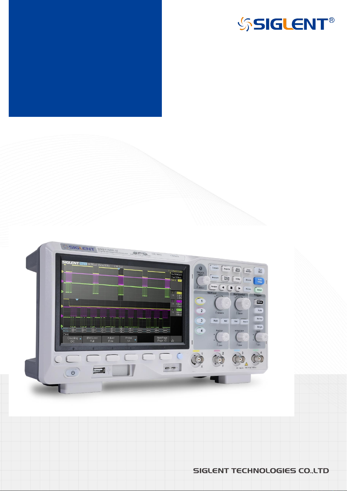
7 -inch TFT -LCD display with 800 * 480 resolution
Most commonly used functions are accessible using 10 different one-button operation keys: Auto Setup, Default,
Cursor, Measure, Roll, History, Persist, Clear Sweep, Zoom, Print
Record Length of up to 14 Mpts
Waveform Capture Rate up to 400,000 wfm/s
Using hardware-based Zoom technologies and max record
length of up to 14 Mpts, users are able to oversample to
capture for longer time periods at higher resolution and
use the zoom feature to see more details within each
signal.
With a waveform capture rate of up to 400,000 wfm/s
(sequence mode), the oscilloscope can easily capture the
unusual or low-probability events.
Functions & Characteristics
7 Inch TFT-LCD Display and 10 One-button Menus
WWW.SIGLENT.COM
3
Page 5
SDS1000X-U Series Digital Oscilloscope
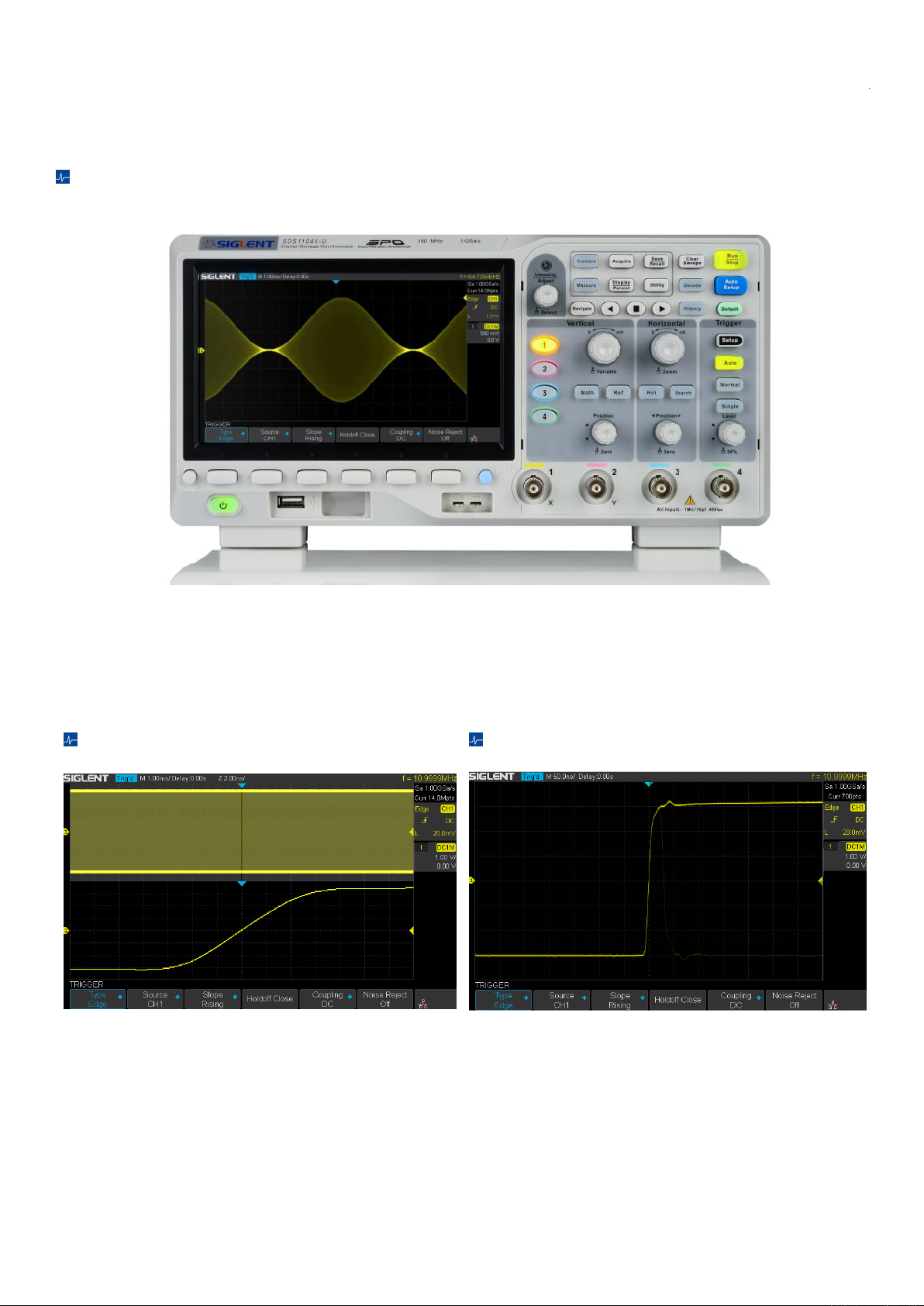
256-Level Intensity Grading and Color Temperature Display
SPO display technology provides fast refresh rates. The
resulting intensity-graded trace is brighter for events that
occur with more frequency and dims when the events occur
with less frequency.
The color temperature display is similar to the intensity-
graded trace function, but the trace occurrence is
represented by different colors (color “temperature”) as
opposed to changes in the intensity of one color. Red colors
represent events that occur more frequently, while blue is
used to mark points that occur less frequently
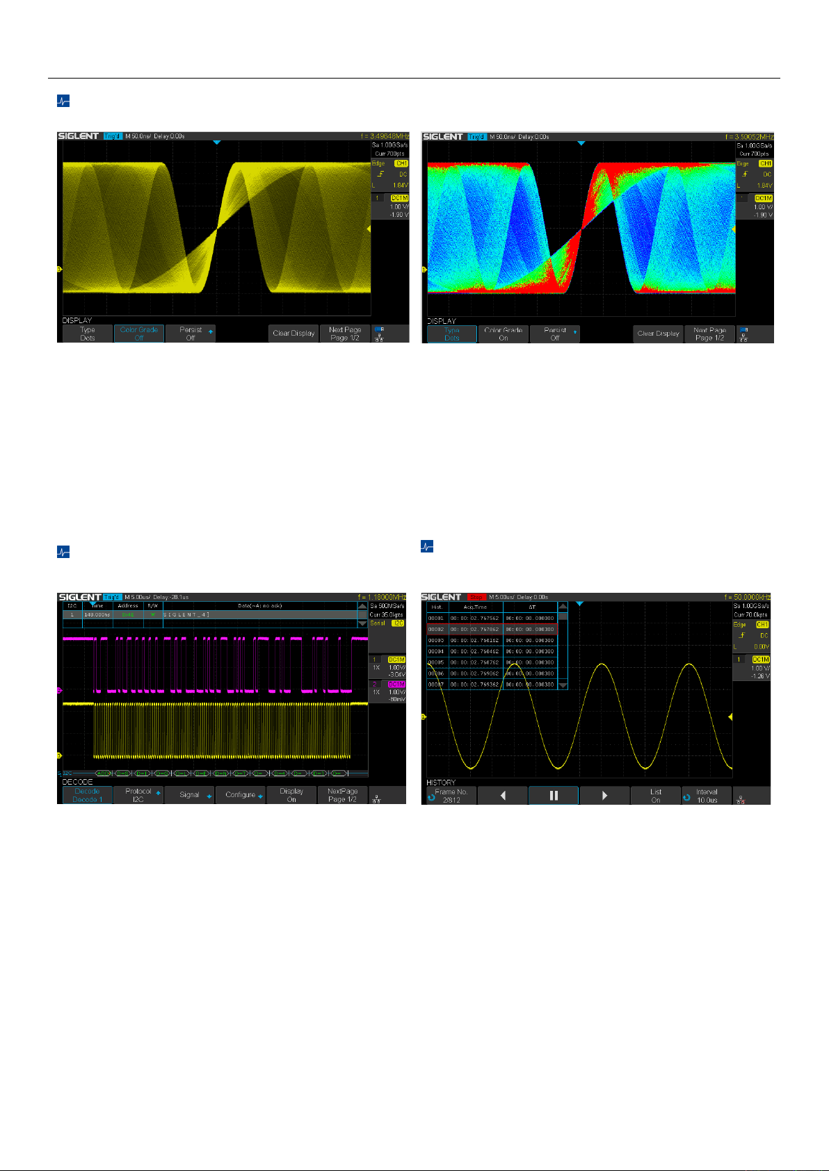
Serial Bus Decoding Function (Standard)
History Waveforms (History) Mode and
Segmented Acquisition (Sequence)
SDS1000X-U displays the decoding through the events list.
Bus protocol information can be quickly and intuitively
displayed in a tabular format.
Playback the latest triggered events using the history
function. Segmented memory collection will store trigger
events into multiple (Up to 80,000) memory segments, each
segment will store triggered waveforms and timestamp of
each frame.
4 WWW.SIGLENT.COM
Page 6
SDS1000X-U Series Digital Oscilloscope
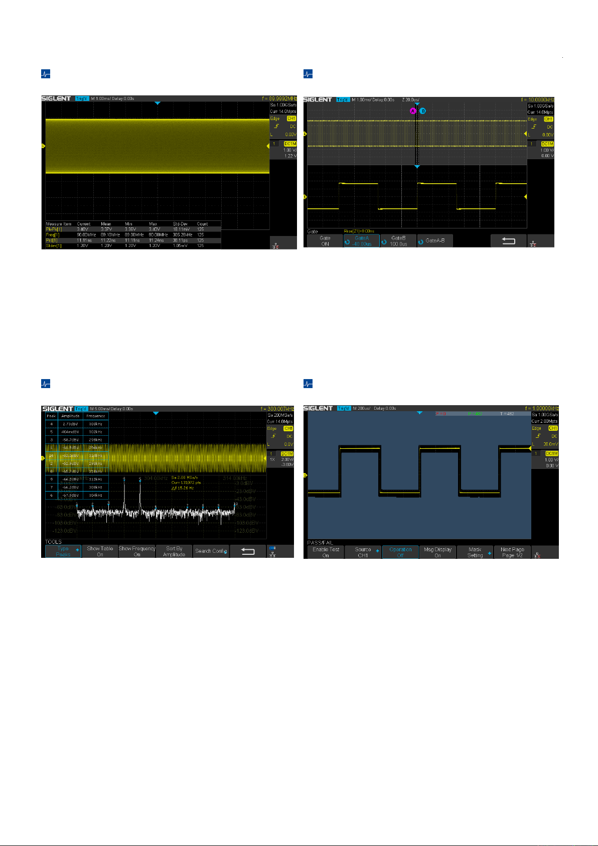
True measurement to 14 M points
Gate and Zoom Measurement
SDS1004X-U can measure all sampled data points up to 14
Mpts. This ensures the accuracy of measurements while the
math co-processor decreases measurement time and
increases ease-of-use.
Through Gate and Zoom measurement, the user can
specify an arbitrary interval of waveform data analysis and
statistics. This helps avoid measurement errors that can be
caused by invalid or extraneous data, greatly enhancing
the measurements’ validity and flexibility.
128k points used to calculate the FFT
Hardware-Based High-Speed Pass/Fail
The new math co-processor enables FFT analysis of
incoming signals using up to 128k samples per waveform.
This provides high frequency resolution with a fast refresh
rate. The FFT function also supports a variety of window
functions so that it can adapt to different spectrum
measurement needs. Four-channel series support Peaks,
Markers, a variety of numbers.
The SDS1000X-U utilizes a hardware-based Pass/Fail
function, performing up to 40,000 Pass / Fail decisions each
second. Easily generate user defined test templates
provide trace mask comparison making it suitable for long-
term signal monitoring or automated production line
testing.
WWW.SIGLENT.COM
5
Page 7

SDS1000X-U Series Digital Oscilloscope
Customizable Default Key
Search and Navigate
The current parameters of the oscilloscope can be preset to
Default Key through the Save menu.
The SDS1000X-U can search events specified by the user in
a frame. It can also navigate by time (delay position) and
historical frames.
Complete Connectivity
SDS1000X-U supports USB Host, USB Device (USB-TMC),
LAN (VXI-11), Pass/Fail and Trigger Out
6 WWW.SIGLENT.COM
Page 8

SDS1000X-U Series Digital Oscilloscope
Acquisition System
Sampling Rate (Max.)
1 GSa/s (One channel), 500 MSa/s(Two channels), 250 MSa/s(Four channels)
Memory Depth (Max.)
14 Mpts
Peak Detect
2 ns
Average
Averages: 4,16, 32, 64, 128, 256, 512, 1024
ERES
Enhance bits: 0.5, 1, 1.5, 2, 2.5, 3
Waveform
interpolation
Sin(x)/x, Linear
Input
Channels
4
Coupling
DC, AC, GND
Impedance
DC: (1 MΩ±2%) || (15 pF ±2 pF)
Max. Input voltage
1 MΩ: ≤400 Vpk (DC + Peak AC <=10 kHz)
CH to CH Isolation
DC-Max BW :>40 dB
Probe attenuation
1E-6X ~ 1E6X
Vertical System
Bandwidth (-3dB)
100 MHz
Vertical Resolution
8-bit
Vertical Scale (Probe
1X)
1 mV/div – 10 V/div (1-2-5 sequence)
Offset Range (Probe
1X)
1 mV- 200 mV: ± 2 V
206 mV- 10 V: ± 100 V
Bandwidth limit
20 MHz ± 40%
Bandwidth Flatness
DC- 10% (BW): ± 1 dB
10% - 50% (BW): ± 2 dB
50% - 100% (BW): + 2 dB/-3 dB
Low frequency
response
(AC coupling -3 dB)
≤2 Hz (at input BNC)
Noise
ST-DEV ≤ 0.2 division (<2 mV/div)
ST-DEV ≤ 0.1 division (≥ 2 mV/div)
SFDR including
harmonics
≥ 35 dB
DC Gain Accuracy
≤ ± 3.0%: 5 mV/div-10 V/div
≤ ± 4.0% : ≤ 2 mV/div
Offset Accuracy
± (1%* Offset+1.5%*8*div+2 mV): ≥2 mV/div
± (1%* Offset+1.5%*8*div+500 uV): 1 mv/div
Rise time
Typical 3.5 ns
Specifications
WWW.SIGLENT.COM
7
Page 9

SDS1000X-U Series Digital Oscilloscope
Overshoot (500 ps
Pulse)
< 10%
Horizontal System
Timebase Scale
2 ns/div-100 s/div
Channel Skew
<100 ps
Waveform Capture
Rate
Up to 100,000 wfm/s (normal mode), 400,000 wfm/s (sequence mode)
Intensity grading
256 Levels
Display Format
Y -T, X -Y, Roll
Timebase Accuracy
±25 ppm
Roll Mode
50 ms/div-100 s/div (1-2-5 sequence)
Trigger System
Mode
Auto, Normal, Single
Level
Internal: ±4.5 div from the center of the screen
Hold off range
80 ns- 1.5 s
Coupling
AC
DC
LFRJ
HFRJ
Noise RJ
Coupling Frequency
Response
DC: Passes all components of the signal
AC: Blocks DC components and attenuates signals below 8Hz
LFRJ: Blocks the DC component and attenuates the low-frequency
components below 2 MHz
HFRJ: Attenuates the high-frequency components above 1.2 MHz
Accuracy (typical)
Internal: ±0.2 div
Sensitivity
DC - Max BW 0.6 div
Jitter
<100 ps
Displacement
Pre-Trigger: 0 - 100% Memory
Delay Trigger: 0 to 10,000 div
Edge Trigger
Slope
Rising, Falling, Rising & Falling
Source
All channels/AC Line
Slope Trigger
Slope
Rising, Falling
Limit Range
<, >, <>, ><
Source
All channels
Time Range
2ns- 4.2s
Resolution
1ns
Pulse Width Trigger
Polarity
+wid , -wid
Limit Range
<, >, <>, ><
8 WWW.SIGLENT.COM
Page 10

SDS1000X-U Series Digital Oscilloscope
Source
All channels
Pulse Range
2 ns - 4.2s
Resolution
1 ns
Video Trigger
Signal Standard
NTSC,PAL,720p/50,720p/60,1080p/50,1080p/60,1080i/50,1080i/60,Custom
Source
All channels
Sync
Any, Select
Trigger condition
Line, Field
Window Trigger
Window Type
Absolute, Relative
Source
All channels
Interval Trigger
Slope
Rising, Falling
Limit Range
<, >, <>, ><
Source
All channels
Time Range
2 ns - 4.2 s
Resolution
1 ns
Dropout Trigger
Timeout Type
Edge, State
Source
All channels
Slope
Rising, Falling
Time Range
2 ns - 4.2 s
Resolution
1ns
Runt Trigger
Polarity
+wid , -wid
Limit Range
<, >, <>, ><
Source
All channels
Time Range
2 ns - 4.2 s
Resolution
1 ns
Pattern Trigger
Pattern Setting
Invalid, Low, High
Logic
AND, OR, NAND, NOR
Source
All channels
Limit Range
<, >, <>, ><
Time Range
2 ns - 4.2 s
Resolution
1 ns
Serial Trigger
I2C Trigger
Condition
Start, Stop, Restart, No Ack, EEPROM, 7-bits Address & Data, 10-bits Address & Data, Data Length
Source(SDA/SCL)
All channels
Data format
Hex
Limit Range
EEPROM: =, >, <
Data Length
EEPROM: 1byte
WWW.SIGLENT.COM
9
Page 11

SDS1000X-U Series Digital Oscilloscope
Addr & Data: 1-2byte
Data Length: 1-12byte
R/W bit
Addr & Data: Read, Write, Do not care
SPI Trigger
Condition
Data
Source(CS/CL/Data)
All channels
Data format
Binary
Data Length
4-96-bit
Bit Value
0, 1, X
Bit Order
LSB, MSB
UART Trigger
Condition
Start, Stop, Data, Parity Error
Source(RX/TX)
All channels
Data format
Hex
Limit Range
=, >, <
Data Length
1 byte
Data Width
5, 6, 7, 8-bits
Parity Check
None, Odd, Even, Space, Mark
Stop Bit
1, 1.5, 2-bits
Idle Level
High, Low
Baud Rate(Selectable)
600/1200/2400/4800/960019200/38400/57600/115200 bit/s
Baud Rate (Custom)
300-5000000 bit/s
CAN Trigger
Condition
Start, Remote, ID, ID + Data, Error
Source
All channels
ID
STD (11-bits), EXT (29-bit)
Data Format
Hex
Data Length
1 -2 byte
Baud Rate
5k/10k/20k/50k/100k/125k/250k/500k/800k/1 Mbit/s
LIN Trigger
Condition
Break, Frame ID, ID+Data, Error
Source
All channels
ID
1byte
Data Format
Hex
Data Length
1-2byte
Baud Rate
(Selectable)
600/1200/2400/4800/9600/19200 bit/s
Baud Rate (Custom)
300 bit/s -20 kbit/s
Search
Event
Edge, Slope, Pulse, Interval, Runt
Event Number
Y-T: 700
10
WWW.SIGLENT.COM
Page 12

SDS1000X-U Series Digital Oscilloscope
ROLL: No limitation
Stop After ROLL: 700
Serial Decoder
Decoders
2
I2C
Signal
SCL, SDA
Address
7, 10 bits
Threshold
-4.5 - 4.5 div
List
1- 7 lines
SPI
Signal
SCL,MISO, MOSI
Edge Select
Rising, Falling
Idle Level
Low, High
Bit Order
MSB, LSB
Threshold
-4.5 - 4.5 div
List
1- 7 lines
UART
Signal
RX, TX
Data Width
5,6,7,8 bits
Parity Check
None, Odd, Even, Space, Mark
Stop Bit
1, 1.5, 2 bits
Idle Level
Low, High
Threshold
-4.5 - 4.5 div
List
1- 7 lines
CAN
Signal
CAN_H, CAN_L
Source
CAN_H, CAN_L
Threshold
-4.5 - 4.5 div
List
1- 7 lines
LIN
LIN Specification
Package Revision
Ver1.3, Ver2.0
Threshold
-4.5 - 4.5 div
List
1- 7 lines
Measurement
Source
All channels, All channels in Zoom, Math, All References, History
Number of
Measurements
Display 4 measurements at the same time. 5 measurements displayed in statistics table.
Measurement Range
Screen or Gate region
Measurement
38Types
WWW.SIGLENT.COM
11
Page 13

SDS1000X-U Series Digital Oscilloscope
Parameters
Vertical
Max
Highest value in input waveform
Min
Lowest value in input waveform
Pk-Pk
Difference between maximum and minimum data values
Ampl
Difference between top and base in a bimodal signal, or between max
and min in an unimodal signal
Top
Value of most probable higher state in a bimodal waveform
Base
Value of most probable lower state in a bimodal waveform
Mean
Average of all data values
Cmean
Average of data values in the first cycle
Stdev
Standard deviation of all data values
Cstd
Standard deviation of all data values in the first cycle
VRMS
Root mean square of all data values
Crms
Root mean square of all data values in the first cycle
FOV
Overshoot after a falling edge;(base -min)/Amplitude
FPRE
Overshoot before a falling edge;(max -top)/Amplitude
ROV
Overshoot after a rising edge;(max -top)/Amplitude
RPRE
Overshoot before a rising edge;(base -min)/Amplitude
Level@X
the voltage value of the trigger point
Horizontal
Period
Time between the middle threshold points of two consecutive, like-
polarity edges
Freq
Reciprocal of period
+Wid
Width measured at 50% level and positive slope
-Wid
Width measured at 50% level and negative slope
Rise Time
Duration of rising edge from 10 -90%
Fall Time
Duration of falling edge from 90 -10%
Bwid
Time from the first rising edge to the last falling edge, or the first falling
edge to the last rising edge at the 50% crossing
+Dut
Time difference between the 50% threshold of a rising edge to the 50%
threshold of the next falling edge of the pulse
-Dut
Time difference between the 50% threshold of a falling edge to the 50%
threshold of the next rising edge of the pulse
Delay
Time from the trigger to the first transition at the 50% crossing
Time@Level
Time from the trigger to each rising edge at the 50% crossing.
When Statistics is Off, it shows the time from the trigger to the last rising
edge at the 50% crossing.
When Statistics is On, it shows the Current, Mean, Min, Max, Standard
Deviation of time from the trigger to each rising edge at the 50% crossing
in multiple frames (number = Count).
Delay
Phase
Phase difference between two edges
FRR
Time from the first rising edge of channel A to the following first rising
edge of channel B
FRF
Time from the first rising edge of channel A to the following first falling
12
WWW.SIGLENT.COM
Page 14

SDS1000X-U Series Digital Oscilloscope
edge of channel B
FFR
Time from the first falling edge of channel A to the following first rising
edge of channel B
FFF
Time from the first falling edge of channel A to the following first falling
edge of channel B
LRR
Time from the first rising edge of channel A to the last rising edge of
channel B
LRF
Time from the first rising edge of channel A to the last falling edge of
channel B
LFR
Time from the first falling edge of channel A to the last rising edge of
channel B
LFF
Time from the first falling edge of channel A to the last falling edge of
channel B
Skew
Time of source A edge minus time of nearest source B edge
Cursors
Manual : Time X1, X2, (X1 -X2), (1/ΔT)
Voltage Y1, Y2, (Y1 -Y2)
Track: Time X1, X2, (X1 -X2)
Statistics
Current, Mean, Min, Max, Stdev, Count
Counter
Hardware 6-digit counter(channels are selectable)
Math
Operation
+ , - , * , / , FFT , d/dt , ∫dt , √
FFT window
Rectangular, Blackman, Hanning, Hamming, Flattop
FFT display
Full Screen, Split, Exclusive
I/O
Standard
USB Host, USB Device, LAN, Pass/Fail, Trigger Out
Pass/Fail
3.3V TTL Output
Display(Screen)
Display Type
7–inch TFT LCD
Display Resolution
800×480 pixels
Display Color
24-bit
Contrast(Typical)
500:1
Backlight
300 nits
Range
8 x 14 divisions
Display(Waveform)
Display Mode
Dot, Vector
Persist Time
Off, 1 Sec, 5 Sec, 10 Sec, 30 Sec, Infinite
Color Display
Normal, Color
Screen Saver
1 min, 5 min, 10 min, 30 min, 1 hour, Off
WWW.SIGLENT.COM
13
Page 15

SDS1000X-U Series Digital Oscilloscope
Language
Simplified Chinese, Traditional Chinese, English, French, Japanese, Korean, German, Russian,
Italian, Portuguese
Environments
Temperature
Operating: 0℃ - +40℃
Non-operating: -20℃ - + 60℃
Humidity
Operating: 85% RH, 40 ℃, 24 hours
Non-operating: 85% RH, 65 ℃, 24 hours
Height
Operating: ≤ 3000 m
Non-operating: ≤ 15,000 m
Standards
Electromagnetic
compatibility
Meets EMC directive (2014/30/EU), meets or exceeds IEC 61326-1:2012/EN61326-1:2013 (Basic)
Conducted disturbance
CISPR 11/EN 55011
CLASS A group 1 , 150kHz-
30MHz
Radiated disturbance
CISPR 11/EN 55011
CLASS A group 1 , 30MHz-
1GHz
Electrostatic discharge (ESD)
IEC 61000-4-2/EN 61000-4-2
4.0 kV(Contact), 8.0 kV(Air)
Radio-frequency
electromagnetic field
Immunity
IEC 61000-4-3/EN 61000-4-3
10 V/m(80 MHz to 1 GHz);
3 V/m(1.4 GHz to 2 GHz);
1 V/m(2.0 GHz to 2.7GHz)
Electrical fast transients (EFT)
IEC 61000-4-4/EN 61000-4-4
2kV (Input AC Power Ports)
Surges
IEC 61000-4-5/EN 61000-4-5
1kV (Line to line)
2kV (Line to ground)
Radio-frequency continuous
conducted Immunity
IEC 61000-4-6/EN 61000-4-6
3 V, 0.15-80MHz
Voltage dips and
interruptions
IEC 61000-4-11/EN 61000-4-
11
Voltage Dips:
0% UT during 1 cycle;
40% UT during 10/12 cycles;
70% UT during 25/30 cycles
Voltage interruptions:0% UT
during 250/300 cycles
Safety
UL 61010-1:2012/R: 2018-11; CAN/CSA-C22.2 No. 61010-1:2012/A1:2018-11.
UL 61010-2-030:2018; CAN/CSA-C22.2 No. 61010-2-030:2018.
Power Supply
Input Voltage
100 ~ 240 Vrms 50/60Hz
100 ~ 120 Vrms 400Hz
Power
50 W Max
14
WWW.SIGLENT.COM
Page 16

SDS1000X-U Series Digital Oscilloscope
Mechanical
Dimensions
Length: 312 mm
Width: 132.6 mm
Height: 151 mm
Weight
N.W: 2.6 kg; G.W: 3.8 kg
Probe
Picture
Model
Specifications &Description
Passive
PP510
Bandwidth: 100MHz, 1X/10X, 1M/10Mohm,300V/600V
Current Probe
CP4020
Bandwidth: 100 KHz, Max. continuous current: 20Arms
Peak current: 60A
Switch Ratio: 50mV/A, 5mV/A, Accuracy: 50mV/A (0.4A -
10Apk)±2%, 5mV/A
(1A-60Apk) ±2%, 9V battery source
CP4050
Bandwidth: 1MHz, Max. continuous current: 50Arms, Peak
current: 140A
Switch Ratio: 500mV/A, 50mV/A
Accuracy: 500mV/A (20mA -14ApK)±3%±20mA , 50mV/A
(200mA -100ApK)
±4%±200mA, 50mV/A (100A -140ApK) ±15%max, 9V battery
source
CP4070
Bandwidth: 150kHz, Max. continuous current: 70Arms,
Peak current: 200A
Switch Ratio: 50mV/A, 5mV/A, Accuracy: 50mV/A (0.4A -
10ApK)±2% , 5mV/A(1A -200ApK) ±2%, 9V battery source
CP5030
Bandwidth: 50 MHz, Max. continuous current: 30Arms,
Peak current: 50A
Switch Ratio: 100mV/A, 1V/A, Accuracy: 1V/A (±1%±1mA),
100mV/A (±1%±10mA), DC12V/1.2A power adapter
CP5030A
Bandwidth: 100 MHz, Max. continuous current: 30Arms,
Peak current: 50A
Switch Ratio: 100mV/A, 1V/A, Accuracy: 1V/A (±1%±1mA),
100mV/A (±1%±10mA), DC12V/1.2A power adapter
Probes and Accessories
WWW.SIGLENT.COM
15
Page 17

SDS1000X-U Series Digital Oscilloscope
CP5150
Bandwidth: 12 MHz, Max. continuous current: 150Arms,
Peak current: 300A
Switch Ratio: 100mV/A, 10mV/A, Accuracy: 100mV/A
(±1%±10mA), 10mV/A (±1%±100mA), DC12V/1.2A power
adapter
CP5500
Bandwidth: 5 MHz, Max. continuous current: 500Arms,
Peak current: 750A
Switch Ratio: 100mV/A, 10mV/A, Accuracy: 100mV/A
(±1%±10mA), 10mV/A(±1%±100mA), DC12V/1.2A power
adapter
Differential
Probe
DPB4080
Bandwidth: 50MHz, Differential Range: 800V (DC + Peak
AC),
100X/200X/500X/1000X, Accuracy: ±1%, DC 9V/1A power
adapter
DPB5150
Bandwidth: 70MHz, Differential Range: 1500V (DC + Peak
AC),50X/500X
Accuracy: ±2%, DC 5V/1A USB adapter
DPB5150A
Bandwidth: 100MHz, Differential Range: 1500V (DC + Peak
AC),
50X/500X , Accuracy: ±2%
DC 5V/1A USB adapter
DPB5700
Bandwidth: 70MHz, Differential Range: 7000V (DC + Peak
AC),
100X/1000X , Accuracy: ±2%,
DC 5V/1A USB adapter
DPB5700A
Bandwidth: 100MHz
Differential Range: 7000V (DC + Peak AC),
100X/1000X
Accuracy: ±2%
DC 5V/1A USB adapter
High Voltage
HPB4010
Bandwidth: 40MHz
Differential Range: DC 10kV, AC (rms): 7kV (sine), AC (Vpp):
20kV (Pulse)
1000X
Accuracy: ≤3%
Isolated front
end
ISFE
Provides isolation between standard oscilloscope
channels, isolation between
the measured signal and ground. Uses USB 5V power
supply, plug and play.
The maximum input voltage allowed is up to ± 600Vpk.
16
WWW.SIGLENT.COM
Page 18

SDS1000X-U Series Digital Oscilloscope
Demo Board
STB-3 Test
Board
Output signals including square, sine, AM, fast edge, pulse,
PWM, I2C,
CAN, LIN etc. Used in teaching and demonstrations.
Rack Mount
SDS1X-E-RMK
The height is 4U.
WWW.SIGLENT.COM
17
Page 19

Ordering Information
Ordering information
Product Name
SDS1104X-U 100MHz Four Channels
Standard Accessories
USB Cable -1
Quick Start -1
Passive Probe -4
Certification -1
Power Cord -1
Optional Accessories
Isolated Front End
ISFE STB Demo Source
STB-3
High Voltage Probe
HPB4010
Current Probes
CP4020/CP4050/CP4070/
CP4070A/CP5030/CP5030A/
CP5150/CP5500
Differential Probes
DPB4080/DPB5150/DPB5150A
/DPB5700/DPB5700A
Rack Mount
SDS1X-E-RMK
SDS1000X-U Series Digital Oscilloscope
18
WWW.SIGLENT.COM
 Loading...