

Page 1
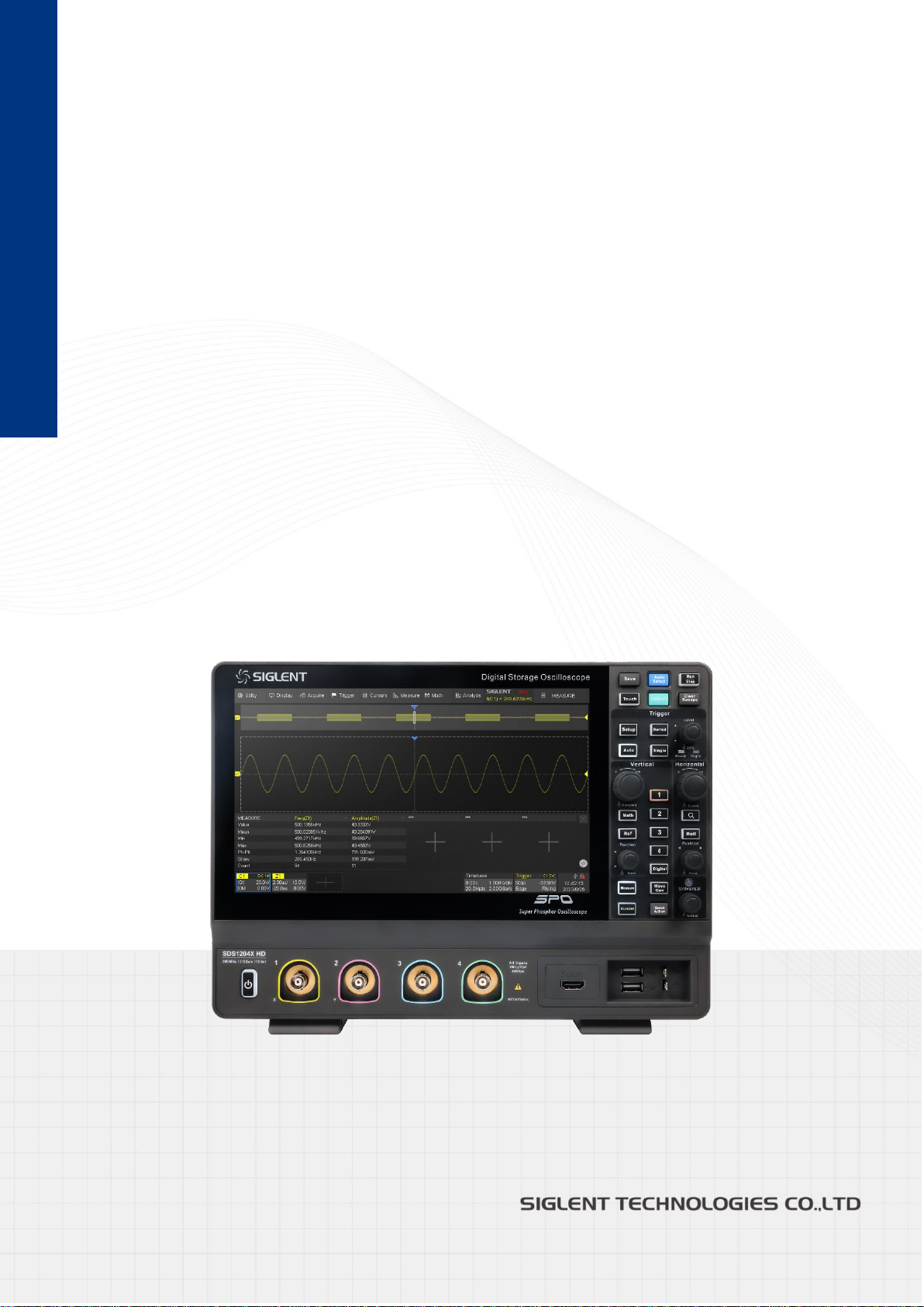
SDS1000X HD Series
Digital Oscilloscope
User Manual
EN01B
Page 2

Page 3

SDS1000XHD Series User Manual
i n t. s i gl e n t. c o m I
Contents
1 Introduction ............................................................................................................ 1
2 Important Safety Information ................................................................................ 2
2.1 General Safety Summary .................................................................................................... 2
2.2 Safety Terms and Symbols ................................................................................................. 4
2.3 Working Environment .......................................................................................................... 5
2.4 Cooling Requirements ......................................................................................................... 6
2.5 Power and Grounding Requirements ................................................................................. 6
2.6 Cleaning .............................................................................................................................. 7
2.7 Abnormal Conditions ........................................................................................................... 7
2.8 Safety Compliance .............................................................................................................. 8
Informations essentielles sur la sécurité ................................................................... 9
Exigence de Sécurité .................................................................................................................... 9
Termes et symboles de sécurité .................................................................................................. 11
Environnement de travail ............................................................................................................ 12
Exigences de refroidissement ..................................................................................................... 13
Connexions d'alimentation et de terre ........................................................................................ 13
Nettoyage .................................................................................................................................... 14
Conditions anormales ................................................................................................................. 15
Conformité en matière de sécurité .............................................................................................. 15
3 First Steps ............................................................................................................ 16
3.1 Delivery Checklist .............................................................................................................. 16
3.2 Quality Assurance ............................................................................................................. 16
3.3 Maintenance Agreement ................................................................................................... 16
4 Document Conventions ....................................................................................... 17
5 Getting Started ..................................................................................................... 18
5.1 Mechanical Dimensions .................................................................................................... 18
5.2 Adjust the Supporting Legs ............................................................................................... 18
5.3 Power on ........................................................................................................................... 19
5.4 Shut down ......................................................................................................................... 19
5.5 System Information ........................................................................................................... 20
5.6 Install Options .................................................................................................................... 20
6 Quick Start ............................................................................................................ 21
Page 4

SDS1000X HD Series User Manual
II i nt. s igl e nt. c o m
6.1 Front Panel Overview ........................................................................................................ 21
6.2 Rear Panel Overview ........................................................................................................ 22
6.3 Connecting to External Devices/Systems ......................................................................... 23
6.3.1 Power Supply .......................................................................................................... 23
6.3.2 LAN .......................................................................................................................... 23
6.3.3 USB Peripherals ...................................................................................................... 23
6.3.4 Auxiliary Output ....................................................................................................... 23
6.3.5 Waveform Generator ............................................................................................... 23
6.3.6 Probes ..................................................................................................................... 24
6.3.7 Logic Probe.............................................................................................................. 25
7 Touch Screen Display .......................................................................................... 26
7.1 Overview ........................................................................................................................... 26
7.2 Menu Bar ........................................................................................................................... 27
7.3 Grid Area ........................................................................................................................... 27
7.4 Channel Descriptor Box .................................................................................................... 29
7.5 Timebase and Trigger Descriptor Boxes ........................................................................... 30
7.6 Dialog Box ......................................................................................................................... 32
7.7 Touch Gestures ................................................................................................................. 34
7.8 Mouse and Keyboard Operation ....................................................................................... 35
7.9 Choosing the Language .................................................................................................... 35
8 Front Panel ................................................................ ................................ ........... 36
8.1 Overview ........................................................................................................................... 36
8.2 Vertical Control .................................................................................................................. 37
8.3 Horizontal Control ............................................................................................................. 38
8.4 Trigger Control .................................................................................................................. 38
8.5 Run/Stop Button ............................................................................................................. 39
8.6 Auto Setup Button .......................................................................................................... 39
8.7 Cursors Control ................................................................................................................. 39
8.8 Universal Knob .................................................................................................................. 39
8.9 Other Buttons .................................................................................................................... 40
9 Multiple Approaches to Recall Functions .......................................................... 41
9.1 Menu Bar ........................................................................................................................... 41
9.2 Descriptor Box ................................................................................................................... 41
9.3 Shortcut Button on the Front panel ................................................................................... 42
10 Quickly Capture the Signal ................................................................................. 43
Page 5

SDS1000XHD Series User Manual
i n t.s i g l en t .co m III
11 Vertical Setup ................................................................................................ ....... 44
11.1 Turn on/off a Channel ........................................................................................................ 44
11.2 Channel Setup................................................................................................................... 45
12 Digital Channels ................................................................................................... 50
12.1 Overview ........................................................................................................................... 50
12.2 Enable/Disable the Digital Channels ................................................................................ 51
12.3 Digital Channel Setup ....................................................................................................... 52
12.4 System .............................................................................................................................. 55
13 Horizontal and Acquisition Setup ....................................................................... 57
13.1 Timebase Setup ................................................................................................................ 57
13.2 Acquisition Setup .............................................................................................................. 58
13.2.1 Overview .................................................................................................................. 58
13.2.2 Acquisition ............................................................................................................... 60
13.2.3 Memory Management.............................................................................................. 60
13.2.4 Roll Mode ................................................................................................................. 61
13.2.5 Sequence ................................................................................................................. 61
13.3 History ............................................................................................................................... 64
14 Zoom ..................................................................................................................... 67
15 Trigger ................................................................................................................... 70
15.1 Overview ........................................................................................................................... 70
15.2 Trigger Setup ..................................................................................................................... 71
15.3 Trigger Level...................................................................................................................... 72
15.4 Trigger Mode ..................................................................................................................... 72
15.5 Trigger Type ...................................................................................................................... 74
15.5.1 Overview .................................................................................................................. 74
15.5.2 Edge Trigger ............................................................................................................ 75
15.5.3 Slope Trigger ........................................................................................................... 75
15.5.4 Pulse Trigger ........................................................................................................... 77
15.5.5 Video Trigger ........................................................................................................... 78
15.5.6 Window Trigger ........................................................................................................ 81
15.5.7 Interval Trigger ......................................................................................................... 82
15.5.8 Dropout Trigger ........................................................................................................ 83
15.5.9 Runt Trigger ............................................................................................................. 83
15.5.10 Pattern Trigger ......................................................................................................... 84
15.5.11 Qualified Trigger ...................................................................................................... 85
Page 6

SDS1000X HD Series User Manual
IV i n t . s i g l e n t . c o m
15.5.12 Nth Edge Trigger ..................................................................................................... 86
15.5.13 Delay Trigger ........................................................................................................... 87
15.5.14 Setup/Hold Trigger ................................................................................................... 87
15.5.15 Serial Trigger ........................................................................................................... 87
15.6 Trigger Source ................................................................................................................... 88
15.7 Holdoff ............................................................................................................................... 88
15.8 Trigger Coupling ................................................................................................................ 89
15.9 Noise Reject ...................................................................................................................... 89
16 Serial Trigger and Decode ................................................................................... 91
16.1 Overview ........................................................................................................................... 91
16.2 I2C Trigger and Serial Decode .......................................................................................... 93
16.2.1 I2C Signal Settings .................................................................................................. 93
16.2.2 I2C Trigger ............................................................................................................... 94
16.2.3 I2C Serial Decode ................................................................................................... 98
16.3 SPI Trigger and Serial Decode ......................................................................................... 99
16.3.1 SPI Signal Settings .................................................................................................. 99
16.3.2 SPI Trigger ............................................................................................................. 102
16.3.3 SPI Serial Decode ................................................................................................. 103
16.4 UART Trigger and Serial Decode ................................................................................... 103
16.4.1 UART Signal Settings ............................................................................................ 103
16.4.2 UART Trigger ......................................................................................................... 104
16.4.3 UART Serial Decode ............................................................................................. 104
16.5 CAN Trigger and Serial Decode ...................................................................................... 104
16.5.1 CAN Signal Settings .............................................................................................. 105
16.5.2 CAN Trigger ........................................................................................................... 105
16.5.3 CAN Serial Decode ............................................................................................... 106
16.6 LIN Trigger and Serial Decode ........................................................................................ 107
16.6.1 LIN Signal Settings ................................................................................................ 107
16.6.2 LIN Trigger ............................................................................................................. 107
16.6.3 LIN Serial Decode ................................................................................................. 108
16.7 FlexRay Serial Decode ................................................................................................... 108
16.7.1 FlexRay Signal Settings ........................................................................................ 108
16.7.2 FlexRay Serial Decode .......................................................................................... 109
16.8 CAN FD Serial Decode .................................................................................................... 110
16.8.1 CAN FD Signal Settings ......................................................................................... 110
16.8.2 CAN FD Serial Decode .......................................................................................... 110
17 Cursors ............................................................................................................... 112
Page 7

SDS1000XHD Series User Manual
i n t. s i gl e nt . co m V
17.1 Overview .......................................................................................................................... 112
17.2 Select and Move Cursors ................................................................................................. 118
18 Measurement ...................................................................................................... 120
18.1 Overview ......................................................................................................................... 120
18.2 Set Parameters ............................................................................................................... 121
18.3 Type of Measurement ..................................................................................................... 124
18.3.1 Vertical Measurement ............................................................................................ 124
18.3.2 Horizontal Measurement ....................................................................................... 126
18.3.3 Miscellaneous Measurements ............................................................................... 127
18.3.4 Delay Measurement .............................................................................................. 128
18.4 Trend ............................................................................................................................... 129
18.5 Track ................................................................................................................................ 130
18.6 Display Mode ................................................................................................................... 130
18.7 Measurement Statistics ................................................................................................... 131
18.8 Statistics Histogram ........................................................................................................ 132
18.9 Simple Measurements .................................................................................................... 133
18.10 Gate ................................................................................................................................. 134
18.11 Amplitude Strategy .......................................................................................................... 135
18.12 Threshold ........................................................................................................................ 135
18.13 Hardware Frequency Counter ......................................................................................... 136
19 Math .................................................................................................................... 137
19.1 Overview ......................................................................................................................... 137
19.2 Arithmetic ........................................................................................................................ 138
19.2.1 Addition / Subtraction / Multiplication / Division .................................................... 138
19.2.2 Identity / Negation .................................................................................................. 139
19.2.3 Average / ERES .................................................................................................... 139
19.2.4 Max-hold / Min-hold ............................................................................................... 140
19.3 Algebra ............................................................................................................................ 141
19.3.1 Differential .............................................................................................................. 141
19.3.2 Integral ................................................................................................................... 141
19.3.3 Square Root........................................................................................................... 142
19.3.4 Absolute ................................................................................................................. 143
19.3.5 Sign ........................................................................................................................ 143
19.3.6 Exp10 ..................................................................................................................... 144
19.3.7 Lg ........................................................................................................................... 144
19.3.8 Interpolate .............................................................................................................. 144
19.4 Filter ................................................................................................................................. 145
Page 8

SDS1000X HD Series User Manual
VI i n t . s i g l e n t . c o m
19.5 Frequency Analysis ......................................................................................................... 147
19.6 Formula Editor ................................................................................................................. 155
20 Reference ........................................................................................................... 157
21 Search ................................................................................................................. 159
22 Navigate ................................................................ ................................ .............. 161
23 Mask Test ............................................................................................................ 166
23.1 Overview ......................................................................................................................... 166
23.2 Mask Setup ..................................................................................................................... 167
23.2.1 Create Mask .......................................................................................................... 168
23.2.2 Mask Editor ............................................................................................................ 168
23.3 Pass/Fail Rule ................................................................................................................. 171
23.4 Operation ......................................................................................................................... 171
24 Counter ............................................................................................................... 172
24.1 Overview ......................................................................................................................... 172
24.2 Mode................................................................................................................................ 173
25 Power Analysis .................................................................................................. 175
25.1 Overview ......................................................................................................................... 175
25.2 Power Quality .................................................................................................................. 176
25.3 Current Harmonics .......................................................................................................... 177
25.4 Inrush Current ................................................................................................................. 179
25.5 Switching Loss ................................................................................................................ 180
25.6 Slew Rate ........................................................................................................................ 183
25.7 Modulation ....................................................................................................................... 183
25.8 Output Ripple .................................................................................................................. 184
25.9 Turn On/Turn Off ............................................................................................................. 184
25.10 Transient Response ........................................................................................................ 186
25.11 PSRR............................................................................................................................... 187
25.12 Power Efficiency .............................................................................................................. 188
25.13 SOA ................................................................................................................................. 189
26 Bode Plot ............................................................................................................ 191
26.1 Overview ......................................................................................................................... 191
26.2 Configuration ................................................................................................................... 192
26.2.1 Connection............................................................................................................. 192
26.2.2 Sweep .................................................................................................................... 192
Page 9

SDS1000XHD Series User Manual
i n t . s i g l ent . c om V I I
26.3 Display ............................................................................................................................. 194
26.4 Data Analysis ................................................................................................................... 196
27 Display ................................................................................................................ 199
28 Arbitrary Waveform Generator ......................................................................... 206
28.1 Overview ......................................................................................................................... 206
28.2 Output .............................................................................................................................. 207
28.3 Wave Type ....................................................................................................................... 207
28.4 Other Setting ................................................................................................................... 208
28.5 System ............................................................................................................................ 210
29 Save/Recall ......................................................................................................... 211
29.1 Save Type ........................................................................................................................ 211
29.2 File Manager ................................................................................................................... 212
29.3 Save and Recall Instances ............................................................................................. 214
30 Utility ................................................................................................................... 218
30.1 System Information ......................................................................................................... 218
30.2 System Setting ................................................................................................................ 218
30.2.1 Language ............................................................................................................... 218
30.2.2 Screen Saver ......................................................................................................... 218
30.2.3 Beeper ................................................................................................................... 219
30.2.4 Auto Power-on ....................................................................................................... 219
30.2.5 Date/Time .............................................................................................................. 219
30.2.6 Reference Position Setting .................................................................................... 220
30.3 Save Button ..................................................................................................................... 222
30.4 Quick Action .................................................................................................................... 223
30.5 I/O Setting ....................................................................................................................... 223
30.5.1 LAN ........................................................................................................................ 223
30.6 Install Options .................................................................................................................. 224
30.7 Maintenance .................................................................................................................... 225
30.7.1 Upgrade ................................................................................................................. 225
30.7.2 Self-Test ................................................................................................................. 226
30.7.3 Self-Calibration ...................................................................................................... 228
30.7.4 Developer Options ................................................................................................. 229
30.8 Service ............................................................................................................................ 230
30.8.1 SMB File Share ..................................................................................................... 230
30.8.2 Web Server ............................................................................................................ 230
30.8.3 Emulation ............................................................................................................... 231
Page 10

SDS1000X HD Series User Manual
VI I I i n t. s i g le n t. c o m
30.8.4 LXI.......................................................................................................................... 231
31 Remote Control .................................................................................................. 232
31.1 Web Browser ................................................................................................................... 232
31.2 Other Connectivity ........................................................................................................... 233
32 Troubleshooting ................................................................................................. 234
Page 11
SDS1000X HD Series User Manual
int sigl e n t .com 1
1 Introduction
A digital oscilloscope is a multi-functional instrument for displaying, analyzing, and storing electrical
signals. It is an indispensable tool for designing, manufacturing, and maintaining electronic equipment.
This user manual includes important safety and installation information related to the SDS1000X HD
series of oscilloscopes and includes simple tutorials for the basic operation of the instrument.
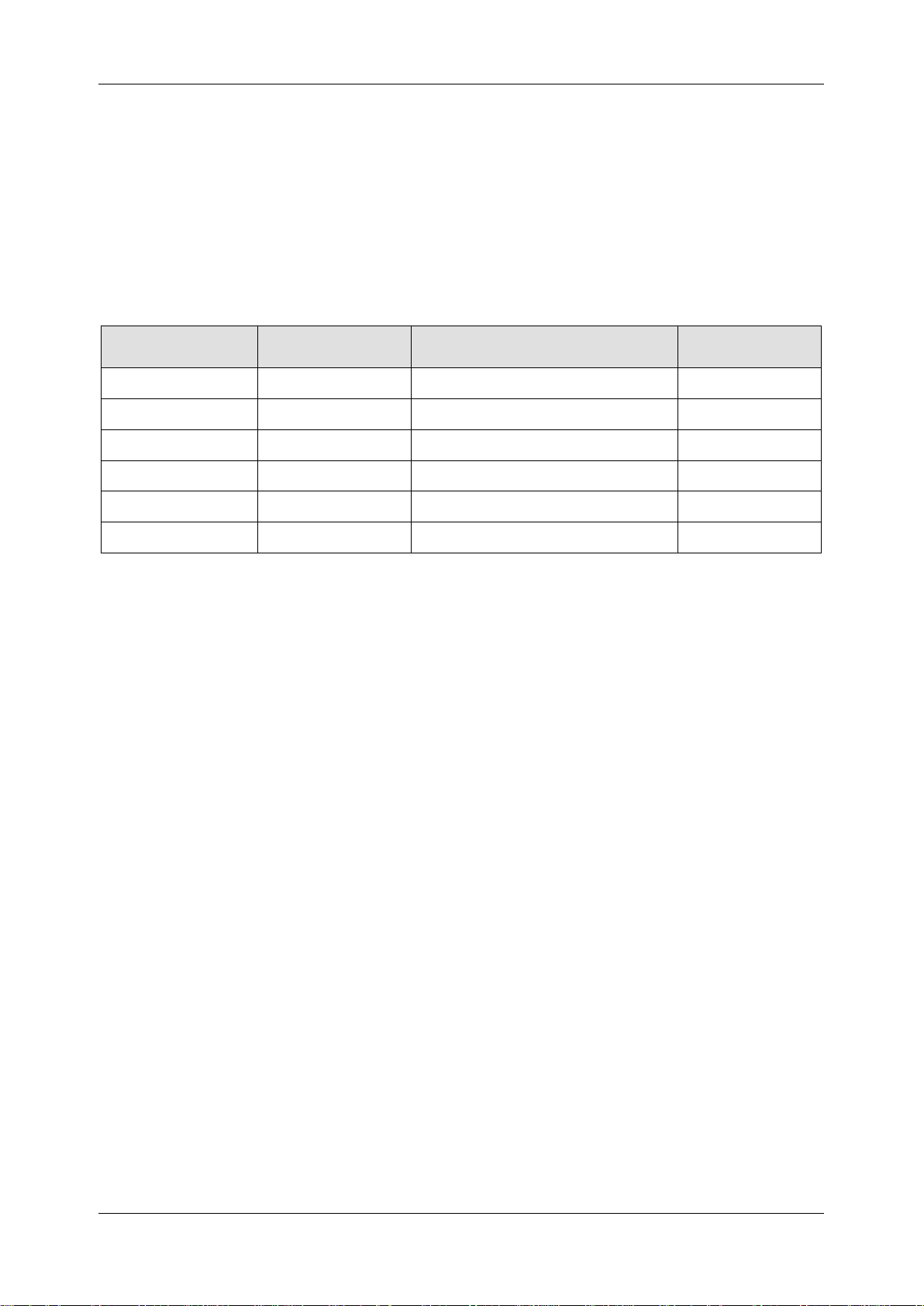
The series includes the following models:
Model
Analogy
Bandwidth
Maximum Sampling Rate
Analog
Channel
SDS1204X HD
200 MHz
2 GSa/s @ each channel
4
SDS1104X HD
100 MHz
2 GSa/s @ each channel
4
SDS1074X HD
70 MHz
2 GSa/s @ each channel
4
SDS1202X HD
200MHZ
2 GSa/s @ each channel
2
SDS1102X HD
100 MHz
2 GSa/s @ each channel
2
SDS1072X HD
70 MHz
2 GSa/s @ each channel
2
Page 12

SDS1000X HD Series User Manual
2 i n t . s i gle n t . c om
2 Important Safety Information
This manual contains information and warnings that must be followed by the user for safe operation
and to keep the product in a safe condition.
2.1 General Safety Summary
Carefully read the following safety precautions to avoid personal injury and prevent damage to the
instrument and any products connected to it. To avoid potential hazards, please use the instrument
as specified.
To Avoid Fire or Personal Injury.
Use Proper Power Line.
Only use a local/state-approved power cord for connecting the instrument to mains power sources.
Ground the Instrument.
The instrument grounds through the protective terra conductor of the power line. To avoid electric
shock, the ground conductor must be connected to the earth. Make sure the instrument is grounded
correctly before connecting its input or output terminals.
Connect the Signal Wire Correctly.
The potential of the signal wire is equal to the earth, so do not connect the signal wire to a high voltage.
Do not touch the exposed contacts or components.
Look over All Terminals’ Ratings.
To avoid fire or electric shock, please look over all ratings and signed instructions of the instrument.
Before connecting the instrument, please read the manual carefully to gain more information about
the ratings.
Equipment Maintenance and Service.
When the equipment fails, please do not dismantle the machine for maintenance. The equipment
contains capacitors, power supply, transformers, and other energy storage devices, which may cause
high voltage damage. The internal devices of the equipment are sensitive to static electricity, and
direct contact can easily cause irreparable damage to the equipment. It is necessary to return to the
factory or the company's designated maintenance organization for maintenance. Be sure to pull out
the power supply when repairing the equipment. Live line operation is strictly prohibited. The
equipment can only be powered on when the maintenance is completed and the maintenance is
confirmed to be successful.
Page 13

SDS1000X HD Series User Manual
int sigl e n t .com 3
Identification of Normal State of Equipment.
After the equipment is started, there will be no alarm information and error information at the interface
under normal conditions. The curve of the interface will scan from left to right freely; if there is a popup window or button during the scanning process or there is an alarm or error prompt, the device may
be in an abnormal state. You need to view the specific prompt information. You can try to restart the
instrument to see if it corrects the error condition. If the fault information is still in place, do not use
the instrument for testing. Contact the manufacturer or the maintenance department designated by
the manufacturer to carry out maintenance before reusing the product.
Not Operate with Suspected Failures.
If you suspect that there is damage to the instrument, please let qualified service personnel check it.
Avoid Circuit or Wire Exposed Components Exposed.
Do not touch exposed contacts or components when the power is on.
Do not operate in wet/damp conditions.
Do not operate in an explosive atmosphere.
Keep the surface of the instrument clean and dry.
Only probe assemblies that meet the requirement of UL61010-031 and CAN/CSA-C22.2
No.61010-031 shall be used.
Only a lithium battery with the same specifications as the original battery should be used to
replace the battery on board.
Do not use the equipment for measurements on mains circuits. Do not use the equipment for
measurements on voltages exceeding the voltage ranges described in the manual. The
maximum additional transient voltage cannot exceed 1300 V.
The responsible body or operator should refer to the instruction manual to preserve the
protection afforded by the equipment. If the equipment is used in a manner not specified by
the manufacturer, the protection provided by the equipment may be impaired.
Any parts of the device and its accessories are not allowed to be changed or replaced, other
than authorized by the manufacturer or agent.
Page 14
SDS1000X HD Series User Manual
4 i n t . s i gle n t . c om
2.2 Safety Terms and Symbols
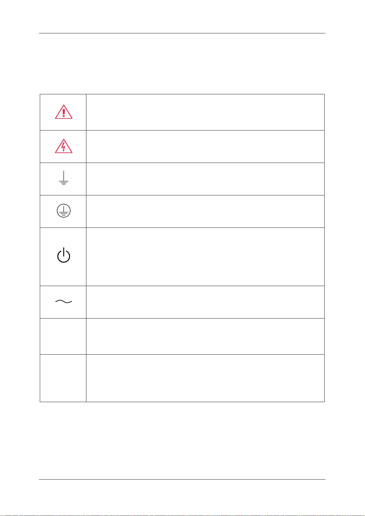
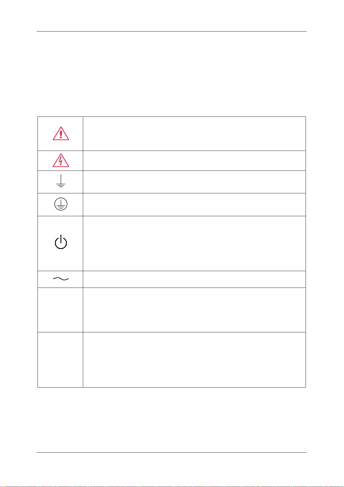
When the following symbols or terms appear on the front or rear panel of the instrument or in this
manual, they indicate special care in terms of safety.
This symbol is used where caution is required. Refer to the accompanying
information or documents to protect against personal injury or damage to the
instrument.
This symbol warns of a potential risk of shock hazard.
This symbol is used to denote the measurement ground connection.
This symbol is used to denote a safety ground connection.
This symbol shows that the switch is an On/Standby switch. When it is pressed,
the scope’s state switches between Operation and Standby. This switch does not
disconnect the device's power supply. To completely power off the scope, the
power cord must be unplugged from the AC socket after the oscilloscope is in the
standby state.
This symbol is used to represent alternating current, or "AC".
CAUTION
The “CAUTION” symbol indicates a potential hazard. It calls attention to a
procedure, practice, or condition which may be dangerous if not followed. Do not
proceed until its conditions are fully understood and met.
WARNING
The “WARNING” symbol indicates a potential hazard. It calls attention to a
procedure, practice, or condition that, if not followed, could cause bodily injury or
death. If a WARNING is indicated, do not proceed until the safety conditions are
fully understood and met.
Page 15
SDS1000X HD Series User Manual
int sigl e n t .com 5
2.3 Working Environment
The design of the instrument has been verified to conform to EN 61010-1 safety standard per the
following limits:
Environment
The instrument is used indoors and should be operated in a clean and dry environment with an
ambient temperature range.
Note: Direct sunlight, electric heaters, and other heat sources should be considered when evaluating
the ambient temperature.
Warning: Do not operate the instrument in explosive, dusty, or humid environments.
Ambient Temperature
Operating: 0 ℃ to +50 ℃
Non-operation: -30 ℃ to +70 ℃
Note: Direct sunlight, radiators, and other heat sources should be taken into account when assessing
the ambient temperature.
Humidity
Operating: 5% ~ 90 %RH, 30 ℃, derate to 50 %RH at 50 ℃
Non-operating: 5% ~ 95% RH
Altitude
Operating: ≤3,000 m, 25 ℃
Non-operating: ≤15,000m
Installation (overvoltage) Category
This product is powered by mains conforming to installation (overvoltage) Category II.
Note: Installation (overvoltage) category I refers to situations where equipment measurement
terminals are connected to the source circuit. In these terminals, precautions are done to limit the
transient voltage to a correspondingly low level.
Installation (overvoltage) category II refers to the local power distribution level which applies to
equipment connected to the AC line (AC power).
Page 16
SDS1000X HD Series User Manual
6 i n t . s i gle n t . c om
Degree of Pollution
The oscilloscopes may be operated in environments of Pollution Degree II.
Note: Degree of Pollution II refers to a working environment that is dry and non-conductive pollution
occurs. Occasional temporary conductivity caused by condensation is expected.
IP Rating
IP20 (as defined in IEC 60529).
2.4 Cooling Requirements
This instrument relies on forced air cooling with internal fans and ventilation openings. Care must be
taken to avoid restricting the airflow around the apertures (fan holes) on each side of the scope. To
ensure adequate ventilation it is required to leave a 15 cm (6 inch) minimum gap around the sides of
the instrument.
CAUTION: Do not block the ventilation holes located on both sides of the scope.
CAUTION: Do not allow any foreign matter to enter the scope through the ventilation
holes, etc.
2.5 Power and Grounding Requirements
The instrument operates with a single-phase, 100 to 240 Vrms (+/-10%) AC power at 50/60 Hz
(+/-5%).
No manual voltage selection is required because the instrument automatically adapts to line voltage.
Depending on the type and number of options and accessories (probes, PC port plug-in, etc.), the
instrument can consume up to 120W of power.
Note: The instrument automatically adapts to the AC line input within the following ranges:
Voltage Range:
90 - 264 Vrms
Frequency Range:
47 - 63 Hz
The instrument includes a grounded cord set containing a molded three-terminal polarized plug and
Page 17
SDS1000X HD Series User Manual
int sigl e n t .com 7
a standard IEC320 (Type C13) connector for making line voltage and safety ground connections. The
AC inlet ground terminal is connected directly to the frame of the instrument. For adequate protection
against electrical shock hazards, the power cord plug must be inserted into a mating AC outlet
containing a safety ground contact. Use only the power cord specified for this instrument and certified
for the country of use.
Warning: Electrical Shock Hazard!
Any interruption of the protective conductor inside or outside of the scope, or
disconnection of the safety ground terminal creates a hazardous situation.
Intentional interruption is prohibited.
The position of the oscilloscope should allow easy access to the socket. To make the oscilloscope
completely power off, unplug the instrument power cord from the AC socket.
The power cord should be unplugged from the AC outlet if the scope is not to be used for an extended
period.
CAUTION: The outer shells of the front panel terminals (CH1, CH2, CH3, CH4, EXT)
are connected to the instrument’s chassis and therefore to the safety
ground.
2.6 Cleaning
Clean only the exterior of the instrument, using a damp, soft cloth. Do not use chemicals or abrasive
elements. Under no circumstances allow moisture to penetrate the instrument. To avoid electrical
shock, unplug the power cord from the AC outlet before cleaning.
Warning: Electrical Shock Hazard!
No operator serviceable parts inside. Do not remove covers.
Refer servicing to qualified personnel
2.7 Abnormal Conditions
Do not operate the scope if there is any visible sign of damage or has been subjected to severe
transport stresses.
If you suspect the scope’s protection has been impaired, disconnect the power cord and secure the
instrument against any unintended operation.
Page 18

SDS1000X HD Series User Manual
8 i n t . s i gle n t . c om
Proper use of the instrument depends on the careful reading of all instructions and labels.
Warning: Any use of the scope in a manner not specified by the manufacturer may
impair the instrument’s safety protection. This instrument should not be
directly connected to human subjects or used for patient monitoring.
2.8 Safety Compliance
This section lists the safety standards with which the product complies.
U.S. nationally recognized testing laboratory listing
UL 61010-1:2012/R: 2018-11. Safety Requirements for Electrical Equipment for Measurement,
Control, and Laboratory Use – Part 1: General Requirements.
UL 61010-2-030:2018. Safety Requirements for Electrical Equipment for Measurement, Control,
and Laboratory Use – Part2-030: Particular requirements for testing and measuring circuits.
Canadian certification
CAN/CSA-C22.2 No. 61010-1:2012/A1:2018-11. Safety Requirements for Electrical Equipment
for Measurement, Control, and Laboratory Use – Part 1: General Requirements.
CAN/CSA-C22.2 No. 61010-2-030:2018. Safety Requirements for Electrical Equipment for
Measurement, Control, and Laboratory Use – Part 2-030: Particular requirements for testing and
measuring circuits.
Page 19

SDS1000X HD Series User Manual
int sigl e n t .com 9
Informations essentielles sur la sécurité
Ce manuel contient des informations et des avertissements que les utilisateurs doivent suivre pour
assurer la sécurité des opérations et maintenir les produits en sécurité.
Exigence de Sécurité
Lisez attentivement les précautions de sécurité ci - après afin d 'éviter les dommages corporels et de
prévenir les dommages aux instruments et aux produits associés. Pour éviter les risques potentiels,
utilisez les instruments prescrits.
Éviter l 'incendie ou les lésions corporelles.
Utilisez un cordon d'alimentation approprié.
N'utilisez que des cordons d'alimentation spécifiques aux instruments approuvés par les autorités
locales.
Mettez l'instrument au sol.
L'instrument est mis à la Terre par un conducteur de mise à la terre de protection du cordon
d'alimentation.Pour éviter un choc électrique, le conducteur de mise à la terre doit être mis à la
terre.Assurez - vous que l'instrument est correctement mis à la terre avant de connecter les bornes
d'entrée ou de sortie de l'instrument.
Connectez correctement le fil de signalisation.
Le potentiel de la ligne de signal est égal au potentiel au sol, donc ne connectez pas la ligne de signal
à haute tension.Ne touchez pas les contacts ou les composants exposés.
Voir les cotes de tous les terminaux.
Pour éviter un incendie ou un choc électrique, vérifiez toutes les cotes et signez les instructions de
l'instrument.Avant de brancher l'instrument, lisez attentivement ce manuel pour obtenir de plus
amples renseignements sur les cotes.
Entretien du matériel.
En cas de défaillance de l'équipement, ne pas démonter et entretenir l'équipement sans autorisation.
L'équipement contient des condensateurs, de l'alimentation électrique, des transformateurs et
d'autres dispositifs de stockage d'énergie, ce qui peut causer des blessures à haute tension. Les
dispositifs internes de l'équipement sont sensibles à l'électricité statique. Le contact direct peut
facilement causer des blessures irrécupérables à l'équipement. L'équipement doit être retourné à
l'usine ou à l'organisme de maintenance désigné par l'entreprise pour l'entretien. L'alimentation
Page 20

SDS1000X HD Series User Manual
10 i n t . s i g l e n t . c o m
électrique doit être retirée pendant l'entretienLa ligne ne doit pas être mise sous tension tant que
l'entretien de l'équipement n'est pas terminé et que l'entretien n'est pas confirmé.
Identification de l'état normal de l'équipement.
Après le démarrage de l'équipement, dans des conditions normales, il n'y aura pas d'information
d'alarme et d'erreur au bas de l'interface, et la courbe de l'interface sera balayée librement de gauche
à droite; si un blocage se produit pendant le processus de numérisation, ou si l'information d'alarme
ou d'erreur apparaît au bas de l'interface, l'équipement peut être dans un état anormal. Pour voir
l'information d'alarme spécifique, vous pouvez d'abord essayer de redémarrerSi l'information sur la
défaillance est toujours présente, ne l'utilisez pas pour l'essai. Contactez le fabricant ou le Service de
réparation désigné par le fabricant pour effectuer l'entretien afin d'éviter d'apporter des données
d'essai erronées ou de mettre en danger la sécurité personnelle en raison de l'utilisation de la
défaillance.
Ne pas fonctionner en cas de suspicion de défaillance.
Si vous soupçonnez des dommages à l'instrument, demandez à un technicien qualifié de vérifier.
L 'exposition du circuit ou de l' élément d 'exposition du fil est évitée.
Lorsque l 'alimentation est connectée, aucun contact ou élément nu n' est mis en contact.
Ne pas fonctionner dans des conditions humides / humides.
Pas dans un environnement explosif.
Maintenez la surface de l 'instrument propre et sec.
Le Circuit d 'alimentation électrique ne peut pas être mesuré à l' aide du dispositif, ni la tension
qui dépasse la plage de tension décrite dans le présent manuel.
Seuls les ensembles de sondes conformes aux spécifications du fabricant peuvent être
utilisés.
L'organisme ou l'opérateur responsable doit se référer au cahier des charges pour protéger la
protection offerte par le matériel.La protection offerte par le matériel peut être compromise si
celui - ci est utilisé de manière non spécifiée par le fabricant.
Aucune pièce du matériel et de ses annexes ne peut être remplacée ou remplacée sans
l'autorisation de son fabricant.
Page 21
SDS1000X HD Series User Manual
int siglent.com 11
Remplacer la batterie dans l 'appareil avec les mêmes spécifications de batterie au lithium.
Termes et symboles de sécurité
Lorsque les symboles ou termes suivants apparaissent sur le panneau avant ou arrière de
l'instrument ou dans ce manuel, ils indiquent un soin particulier en termes de sécurité.
Ce symbole est utilisé lorsque la prudence est requise. Reportez-vous aux
informations ou documents joints afin de vous protéger contre les blessures ou
les dommages à l'instrument.
Ce symbole avertit d'un risque potentiel de choc électrique.
Ce symbole est utilisé pour désigner la connexion de terre de mesure.
Ce symbole est utilisé pour indiquer une connexion à la terre de sécurité.
Ce symbole indique que l'interrupteur est un interrupteur marche / veille. Lorsqu'il
est enfoncé, l'état de l'oscilloscope bascule entre Fonctionnement et Veille. Ce
commutateur ne déconnecte pas l'alimentation de l'appareil. Pour éteindre
complètement l'oscilloscope, le cordon d'alimentation doit être débranché de la
prise secteur une fois l'oscilloscope en état de veille.
Ce symbole est utilisé pour représenter un courant alternatif, ou "AC".
CAUTION
Le symbole " CAUTION" indique un danger potentiel. Il attire l'attention sur une
procédure, une pratique ou une condition qui peut être dangereuse si elle n'est
pas suivie. Ne continuez pas tant que ses conditions n'ont pas été entièrement
comprises et remplies.
WARNING
Le symbole " WARNING" indique un danger potentiel. Il attire l'attention sur une
procédure, une pratique ou une condition qui, si elle n'est pas suivie, pourrait
entraîner des blessures corporelles ou la mort. Si un AVERTISSEMENT est
indiqué, ne continuez pas tant que les conditions de sécurité ne sont pas
entièrement comprises et remplies.
Page 22
SDS1000X HD Series User Manual
12 i n t . s i g l e n t . c o m
Environnement de travail
La conception de l'instrument a été certifiée conforme à la norme EN 61010-1, sur la base des valeurs
limites suivantes:
Environnement
L'instrument doit être utilisé à l'intérieur dans un environnement propre et sec dans la plage de
température ambiante.
Note: la lumière directe du soleil, les réchauffeurs électriques et d'autres sources de chaleur doivent
être pris en considération lors de l'évaluation de la température ambiante.
Attention: ne pas utiliser l'instrument dans l'air explosif, poussiéreux ou humide.
Température ambiante
En fonctionnement: 0 ℃ à +50 ℃
Hors fonctionnement: -30 ℃ à +70 ℃
Note: pour évaluer la température de l'environnement, il convient de tenir compte des rayonnements
solaires directs, des radiateurs thermiques et d'autres sources de chaleur.
Humidité
Fonctionnement: 5% ~ 90% HR, 30 °C, 50 °C réduit à 50% HRHors fonctionnement: 5% ~ 95%,
65 ℃, 24 heures
Altitude
Fonctionnement: ≤ 3000 m
À l'arrêt: ≤ 15,000 m
Catégorie d 'installation (surtension)
Ce produit est alimenté par une alimentation électrique conforme à l 'installation (surtension)
Catégorie II.
Installation (overvoltage) Category Definitions Définition de catégorie d 'installation
(surtension)
La catégorie II d'installation (surtension) est un niveau de signal applicable aux terminaux de mesure
d' équipement reliés au circuit source.Dans ces bornes, des mesures préventives sont prises pour
limiter la tension transitoire à un niveau inférieur correspondant.
Page 23
SDS1000X HD Series User Manual
int si glent.com 13
La catégorie II d'installation (surtension) désigne le niveau local de distribution d 'énergie d' un
équipement conçu pour accéder à un circuit alternatif (alimentation alternative).
Degré de pollution
Un oscilloscope peut être utilisé dans un environnement Pollution Degree II.
Note: Pollution Degree II signifie que le milieu de travail est sec et qu'il y a une pollution non
conductrice.Parfois, la condensation produit une conductivité temporaire.
IP Rating
IP20 (as defined in IEC 60529).
Exigences de refroidissement
Cet instrument repose sur un refroidissement à air forcé avec des ventilateurs internes et des
ouvertures de ventilation. Des précautions doivent être prises pour éviter de restreindre le flux d'air
autour des ouvertures (trous de ventilateur) de chaque côté de la lunette. Pour assurer une ventilation
adéquate, il est nécessaire de laisser un espace minimum de 15 cm (6 pouces) sur les côtés de
l'instrument.
ATTENTION: Ne bloquez pas les trous de ventilation situés des deux côtés de la
lunette.
ATTENTION: Ne laissez aucun corps étranger pénétrer dans la lunette par les trous
de ventilation, etc.
Connexions d'alimentation et de terre
L'instrument fonctionne avec une alimentation CA monophasée de 100 à 240 Vrms (+/- 10%) à 50/60
Hz (+/- 5%).
Aucune sélection manuelle de la tension n'est requise car l'instrument s'adapte automatiquement à
la tension de ligne.
Selon le type et le nombre d'options et d'accessoires (sondes, plug-in de port PC, etc.), l'instrument
peut consommer jusqu'à 120 W d'énergie.
Page 24
SDS1000X HD Series User Manual
14 i n t . s i g l e n t . c o m
Remarque: l'instrument s'adapte automatiquement à l'entrée de ligne CA dans les plages suivantes:
Plage de tension:
90 - 264 Vrms
Gamme de fréquences:
47 - 63 Hz
L'instrument comprend un jeu de cordons mis à la terre contenant une fiche polarisée à trois bornes
moulée et un connecteur standard IEC320 (Type C13) pour établir la tension de ligne et la connexion
de mise à la terre de sécurité. La borne de mise à la terre de l'entrée CA est directement connectée
au châssis de l'instrument. Pour une protection adéquate contre les risques d'électrocution, la fiche
du cordon d'alimentation doit être insérée dans une prise secteur correspondante contenant un
contact de sécurité avec la terre. Utilisez uniquement le cordon d'alimentation spécifié pour cet
instrument et certifié pour le pays d'utilisation.
Avertissement: risque de choc électrique!
Toute interruption du conducteur de terre de protection à l'intérieur ou à l'extérieur
de la portée ou la déconnexion de la borne de terre de sécurité crée une situation
dangereuse.
L'interruption intentionnelle est interdite.
La position de l'oscilloscope doit permettre un accès facile à la prise. Pour éteindre complètement
l'oscilloscope, débranchez le cordon d'alimentation de l'instrument de la prise secteur.
Le cordon d'alimentation doit être débranché de la prise secteur si la lunette ne doit pas être utilisée
pendant une période prolongée.
ATTENTION: les enveloppes extérieures des bornes du panneau avant (CH1, CH2,
CH3, CH4, EXT) sont connectées au châssis de l'instrument et donc
à la terre de sécurité.
Nettoyage
Nettoyez uniquement l'extérieur de l'instrument à l'aide d'un chiffon doux et humide. N'utilisez pas de
produits chimiques ou d'éléments abrasifs. Ne laissez en aucun cas l'humidité pénétrer dans
l'instrument. Pour éviter les chocs électriques, débranchez le cordon d'alimentation de la prise secteur
avant de le nettoyer.
Avertissement: risque de choc électrique!
Aucune pièce réparable par l'opérateur à l'intérieur. Ne retirez pas les capots.
Confiez l'entretien à un personnel qualifié
Page 25
SDS1000X HD Series User Manual
int si glent.com 15
Conditions anormales
Utilisez l'instrument uniquement aux fins spécifiées par le fabricant.
N'utilisez pas la lunette s'il y a des signes visibles de dommages ou si elle a été soumise à de fortes
contraintes de transport.
Si vous pensez que la protection de l'oscilloscope a été altérée, débranchez le cordon d'alimentation
et sécurisez l'instrument contre toute opération involontaire.
Une bonne utilisation de l'instrument nécessite la lecture et la compréhension de toutes les
instructions et étiquettes.
Avertissement: Toute utilisation de l'oscilloscope d'une manière non spécifiée par
le fabricant peut compromettre la protection de sécurité de
l'instrument. Cet instrument ne doit pas être directement connecté
à des sujets humains ni utilisé pour la surveillance des patients.
Conformité en matière de sécurité
La présente section présente les normes de sécurité applicables aux produits.
U.S. nationally recognized testing laboratory listing
◼ UL 61010-1:2012/R:2018-11. Prescriptions en matière de sécurité pour les appareils électriques
utilisés en laboratoire et de mesure - partie 1: prescriptions générales.
◼ UL 61010-2-030:2018. Prescriptions de sécurité pour les appareils électriques de mesure, de
contrôle et de laboratoire - partie 2 - 030: prescriptions spéciales pour les circuits d 'essai et de
mesure.
Canadian certification
◼ CAN/CSA-C22.2 No. 61010-1:2012/A1:2018-11. Prescriptions en matière de sécurité pour les
appareils électriques utilisés en laboratoire et de mesure - partie 1: prescriptions générales.
◼ CAN/CSA-C22.2 No. 61010-2-030:2018. Prescriptions de sécurité pour les appareils électriques
de mesure, de contrôle et de laboratoire - partie 2 - 030: prescriptions spéciales pour les circuits
d 'essai et de mesure.
Page 26

SDS1000X HD Series User Manual
16 i n t . s i g l e n t . c o m
3 First Steps
3.1 Delivery Checklist
First, verify that all items listed on the packing list have been delivered. If you note any omissions or
damage, please contact your nearest SIGLENT customer service center or distributor as soon as
possible. If you fail to contact us immediately in case of omission or damage, we will not be
responsible for replacement.
3.2 Quality Assurance
The oscilloscope has a 3-year warranty (1-year warranty for probes and accessories) from the date
of shipment, during normal use and operation. SIGLENT can repair or replace any product that is
returned to the authorized service center during the warranty period. We must first examine the
product to make sure that the defect is caused by the process or material, not by abuse, negligence,
accident, abnormal conditions, or operation.
SIGLENT shall not be responsible for any defect, damage, or failure caused by any of the following:
a) Attempted repairs or installations by personnel other than
SIGLENT
.
b) Connection to incompatible devices/incorrect connection.
c) For any damage or malfunction caused by the use of non-
SIGLENT
supplies. Furthermore,
SIGLENT
shall not be obligated to service a product that has been modified. Spare,
replacement parts, and repairs have a 90-day warranty.
The oscilloscope's firmware has been thoroughly tested and is presumed to be functional.
Nevertheless, it is supplied without a warranty of any kind covering detailed performance. Products
not made by SIGLENT are covered solely by the warranty of the original equipment manufacturer.
3.3 Maintenance Agreement
We provide various services based on maintenance agreements. We offer extended warranties as
well as installation, training, enhancement and on-site maintenance, and other services through
specialized supplementary support agreements. For details, please consult your local SIGLENT
customer service center or distributor.
Page 27
SDS1000X HD Series User Manual
int si glent.com 17
4 Document Conventions
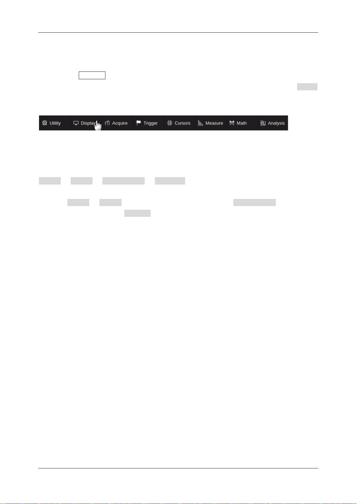
For convenience, text surrounded by a box border is used to represent the button of the front panel.
For example, Default represents the "Default" button on the front panel. Text with shading is used
to represent the touchable or clickable menu/button/region on the touch screen. For example, Display
represents the "Display" menu on the screen:
For the operations that contain multiple steps, the description is in the form of "Step 1 > Step 2 >...".
As an example, follow each step in the sequence to enter the upgrade interface:
Utility > Menu > Maintenance > Upgrade
Click the Utility > Menu in the menu bar as step 1, click the Maintenance option on the
screen as step 2, and click the Update option on the screen as step 3 to enter the upgrade interface.
Page 28
SDS1000X HD Series User Manual
18 i n t . s i g l e n t . c o m
5 Getting Started
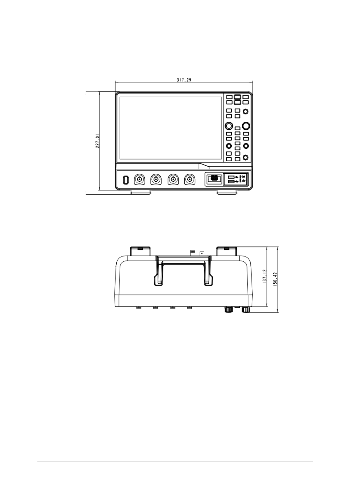
5.1 Mechanical Dimensions
Front View
Top View
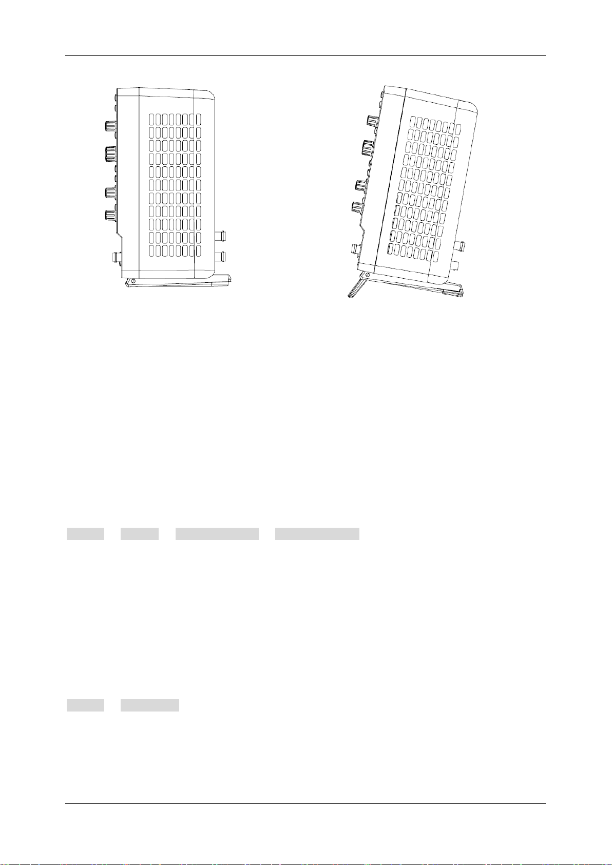
5.2 Adjust the Supporting Legs
Adjust the supporting legs properly to use them as stands to tilt the oscilloscope upwards for stable
placement as well as easier operation and observation of the instrument.
Page 29
SDS1000X HD Series User Manual
int si glent.com 19
5.3 Power on
SDS1000X HD provides two ways for power on, which are:
Auto Power-on
When the “Auto Power-on” option is enabled, once the oscilloscope is connected to the AC power
supply through the power cord, the oscilloscope boots automatically. This is useful in automated or
remote applications where physical access to the instrument is difficult or impossible.
Steps for enabling the “Auto Power-on” function:
Utility > Menu > System Setting > Auto Power On
Power on by Manual
When the " Auto Power-on” option is disabled, the power button on the front panel is the only control
for the power state of the oscilloscope.
5.4 Shut down
Press the power button to turn off the oscilloscope. Or follow the steps below:
Utility > Shutdown
Note: The Power button does not disconnect the oscilloscope from the AC power supply. The only
way to fully power down the instrument is to unplug the AC power cord from the outlet. The power
cord should be unplugged from the AC outlet if the scope is not to be used for an extended period.
Page 30

SDS1000X HD Series User Manual
20 i n t . s i g l e n t . c o m
5.5 System Information
Follow the steps below to examine the software and hardware versions of the oscilloscope.
Utility > Menu > System Info
See the section “System Information” for details.
5.6 Install Options
A license is necessary to unlock a software option. See the section "Install Option" for details.
Page 31
SDS1000X HD Series User Manual
int si glent.com 21
6 Quick Start
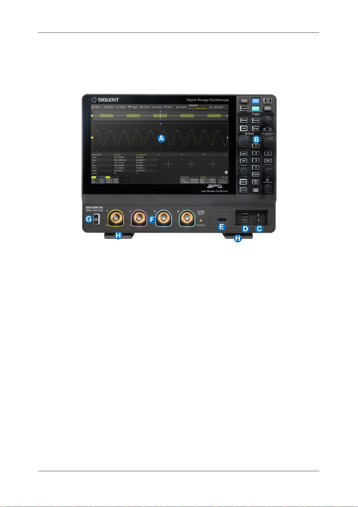
6.1 Front Panel Overview
A.
Touch Screen Display:
The display and major functions area. See the "Touch Screen Display"
chapter for more details
B.
Front Panel:
Includes knobs and buttons. See the "Front Panel" chapter for more details
C.
Probe Compensation/ Ground Terminal:
Supplies a 0-3 V, 1 kHz square wave for
compensating the probes
D.
USB 2.0 Host Ports:
Connect the USB host ports to USB storage devices for data transfer or a
USB mouse/keyboard for control
E.
Digital Input Connector:
Receives digital signals from the SLA1016 digital probe (Non standard
HDMI interface)
F.
Analog Input Connectors
G.
Power Switch
H.
Supporting Legs:
Adjust the supporting legs properly to use them as stands to tilt the
oscilloscope for stable positioning of the oscilloscope
Page 32
SDS1000X HD Series User Manual
22 i n t . s i g l e n t . c o m
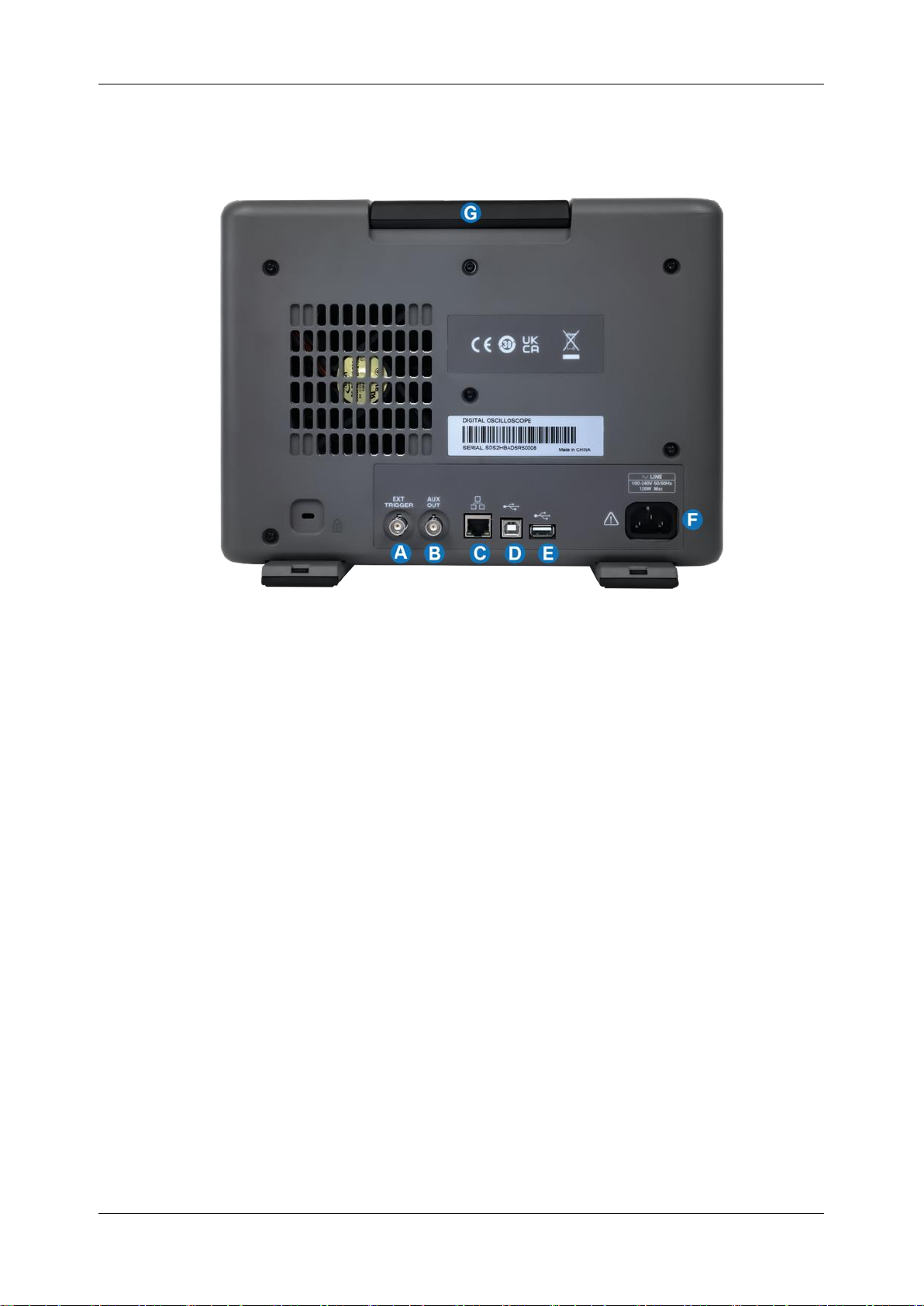
6.2 Rear Panel Overview
A.
Ext Trigger Input
B.
Auxiliary Out:
Outputs the trigger indicator. When Mask Test is enabled, outputs the pass / fail
signal
C.
10M / 100M LAN Port:
Connect the port to the network for remote control
D.
USB 2.0 Device Port:
Connect with a PC for remote control
E.
USB 2.0 Host Port:
Connect with a USB storage device or USB mouse/keyboard
F.
AC Power Input
G.
Handle
Page 33

SDS1000X HD Series User Manual
int si glent.com 23
6.3 Connecting to External Devices/Systems
6.3.1 Power Supply
The standard power supply for the instrument is 100~240 V, 50/60 Hz. Please use the power cord
provided with the instrument to connect it to AC power.
6.3.2 LAN
Connect the LAN port to the network with a network cable with an RJ45 connector for remote control.
See chapter “Remote Control” for detailed information on controlling the instrument with a computer.
Follow the steps below to set LAN connection:
Utility > Menu > I/O > LAN Config
See section “LAN” for details of the configuration.
6.3.3 USB Peripherals
Connect a USB storage device (FAT32 format recommended) to one of the USB host ports for data
transfer, or connect a USB mouse/keyboard to one of the USB host ports for controlling the instrument.
See chapter “Save/Recall” for details of data transfer.
6.3.4 Auxiliary Output
When Mast Test is enabled, the port outputs the pass/fail signal, otherwise, it outputs the trigger
indicator. The trigger indicator can be used to measure the waveform capture rate.
See the chapter “Mask Test” for more details on the pass/fail output.
6.3.5 Waveform Generator
Activate the SDS1000XHD-FG option and connect the SAG1021I USB function / arbitrary waveform
generator module to any USB host port on the oscilloscope. The oscilloscope then can control the
USB module to output specified waveforms.
Press the WaveGen button on the front panel or touch the screen Utility > Wave Gen to set
the waveform.
See chapters “Arbitrary Waveform Generator” and “Bode Plot” for more relative information.
Page 34
SDS1000X HD Series User Manual
24 i n t . s i g l e n t . c o m
6.3.6 Probes
The SDS1000X HD series oscilloscope supports active probes and passive probes. The
specifications and probe documents can be obtained at int.siglent.com, www.siglentna.com, or
www.siglenteu.com.
Probe Compensation
When a passive probe is used for the first time, you should compensate it to match the input channel
of the oscilloscope. Non-compensated or poorly compensated probes may increase measurement
inaccuracy or error. The probe compensation procedures are as follows:
1. Connect the coaxial cable interface (BNC connector) of the passive probe to any channel of the
oscilloscope.
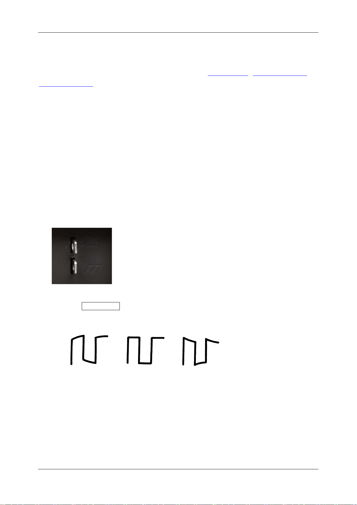
2. Connect the probe to the “Compensation Signal Output Terminal” (Cal) on the front of the
oscilloscope. Connect the ground alligator clip of the probe to the “Ground Terminal” under the
compensation signal output terminal.
3. Press the Auto Setup button.
4. Check the waveform displayed and compare it with the following.
Under
Compensated
Perfectly
Compensated
Over
Compensated
5. Use a non-metallic driver to adjust the low-frequency compensation adjustment hole on the probe
until the waveform displayed is as the “Perfectly compensated” in the figure above.
It’s not necessary to compensate active probes like the SIGLENT SAP series.
Page 35
SDS1000X HD Series User Manual
int si glent.com 25
6.3.7 Logic Probe
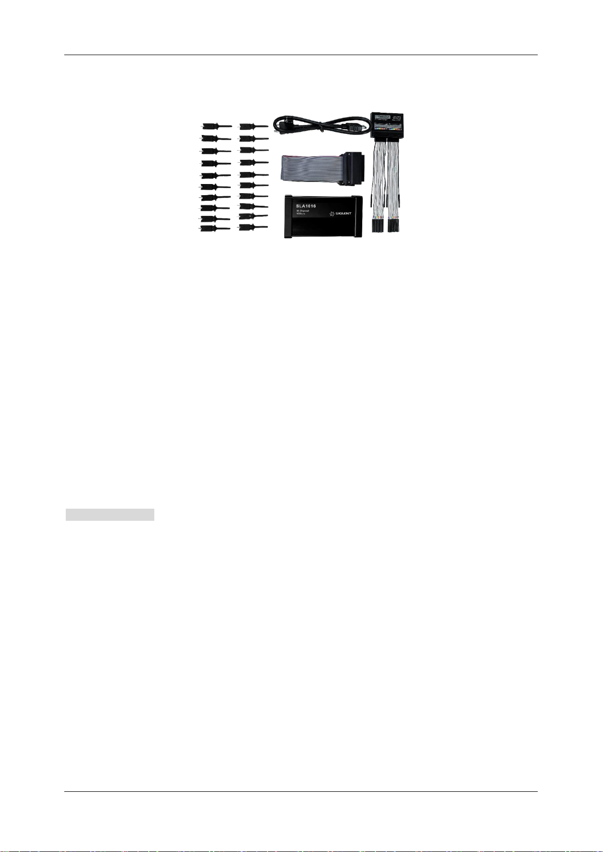
To connect the logic probe: The SLA1016 probe consists of five parts: the SLA1016 probe, the
SUBS interface cable, the flat wire, the flying wire, and the probe clip. The installation is carried out
as follows:
1. Connect one end of the SUBS interface cable to the logical port of the SDS1000X HD and the
other end to the interface of the SLA1016 probe;
2. The interface on the SLA1016 probe is fixed and the flat cables are connected in the
corresponding direction;
3. The flat wire and the flying wire are connected according to the corresponding interface;
4. Finally, connect the short flying wire to the GND of the circuit under test, and connect the long
flying wire to the circuit under test through the probe clip.
To remove the logic probe: After using, if you want to unplug the device, you need to touch the
Remove Device through the digital menu interface. When the oscilloscope interface pops up
“Digital Device Disconnected”, you can remove the SLA1016 probe.
Note:
There are two indicator lights on the side of the SLA1016, one red light (Power) and one green light
(Ready)
Red light: SLA1016 is permanently on when the power supply is normal, and flashing or not on
indicates abnormal power supply.
Green light: When SLA1016 is connected to the oscilloscope, the green light is turned on and
extinguished, entering a slow flashing (1 second cycle) state, and finally remaining on for a long
time. When there is data transmission, the green light flashes quickly (0.5 second cycle).
See chapter “Digital Channels” for more information.
Page 36
SDS1000X HD Series User Manual
26 i n t . s i g l e n t . c o m
7 Touch Screen Display
7.1 Overview
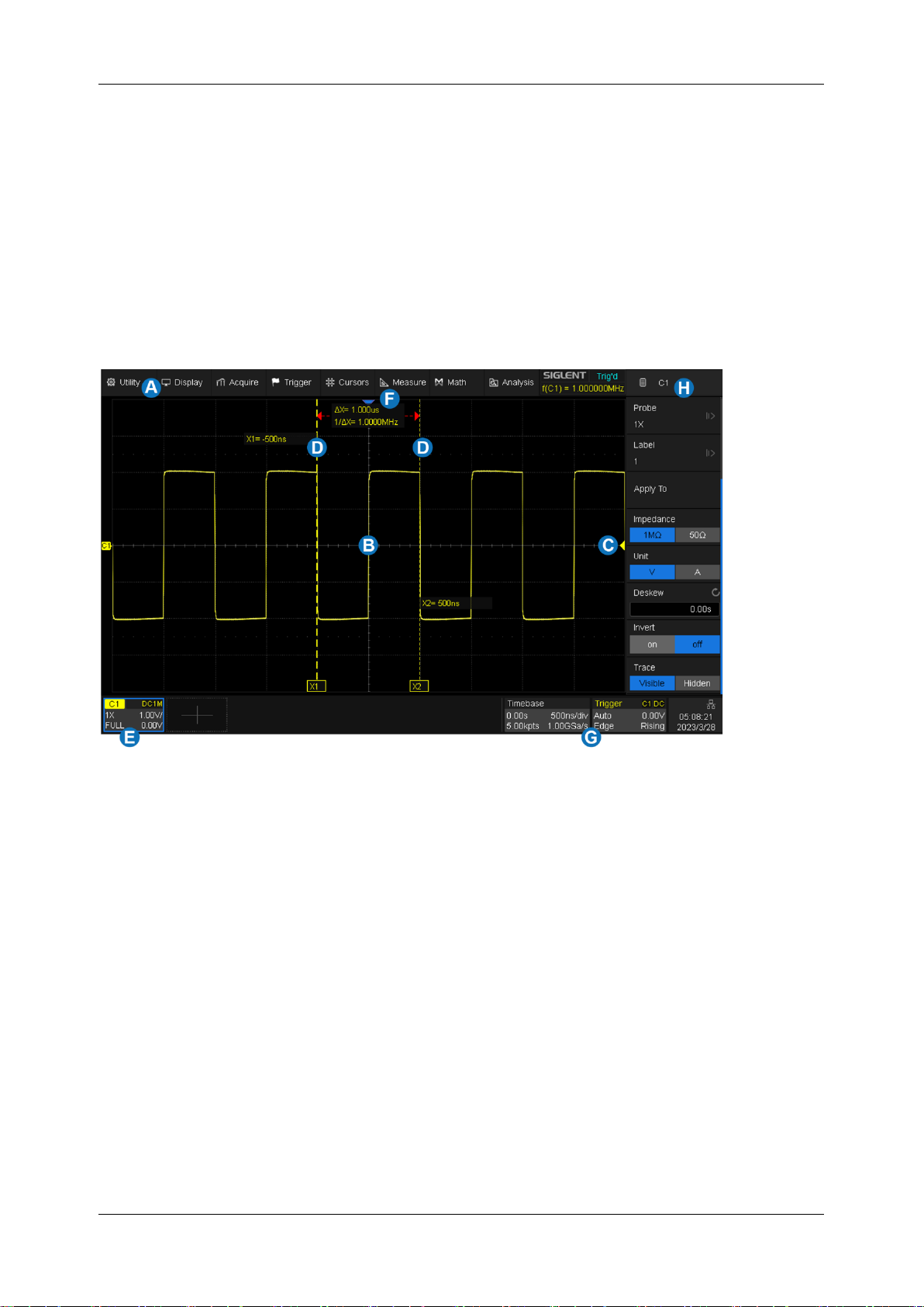
The entire SDS1000X HD display is a capacitive touch screen. Use your fingers to touch, drag, pinch,
spread, or draw a selection box. Many controls that display information also work as “buttons” to
access other functions. If you are using a mouse, you can click anywhere that you can touch to
activate a control. You can alternate between clicking and touching the control, whichever is most
convenient.
A. Menu Bar
B. Grid Area
C. Trigger Level Indicator
D. Cursors
E. Channel Descriptor Boxes
F. Trigger Delay Indicator
G. Timebase and Trigger Descriptor Boxes
H. Dialog Box
Page 37

SDS1000X HD Series User Manual
int si glent.com 27
Trigger Level Line (Vertical) and Trigger Delay Indicator (Horizontal) show the trigger position of
the waveform.
Cursors show where measurement points have been set. Move the cursors to quickly reposition the
measurement point.
Channel Descriptor boxes include analog channels (Cn), digital channels (D), math (Fx), and
reference (Ref). They are located under the grid area, showing the parameters of the corresponding
traces. Touching the boxes creates a dialog box.
Timebase and Trigger Descriptor boxes show the parameters of the timebase and trigger
respectively. Touching the boxes creates a dialog box for the selected item.
The backlight of the display is adjustable. Follow the steps below to adjust the backlight:
Display > Menu > LCD Brightness
7.2 Menu Bar
Menu bar with drop-down menus lets you access set-up dialogs and other functions. All functionality
can be accessed through the menu bar. It is not necessary for common operations. You can enter
most menus by using the front panel or parameter description labels instead of the menu bar. However,
the following operations can only be accessed through the menu bar:
Utility > Help
Utility > Save/Recall
Utility > Reboot
Display
Acquire
7.3 Grid Area
The grid area displays the waveform traces. Traces can be moved by dragging and re-scaled by pinch
and spread. The area is divided into 8 (vertical) * 10 (horizontal) grids. The best display effect can be
obtained by adjusting the waveform intensity and graticule. Follow the steps below to set these
parameters:
Display > Menu > Intensity ,
Page 38
SDS1000X HD Series User Manual
28 i n t . s i g l e n t . c o m
Display > Menu > Graticule
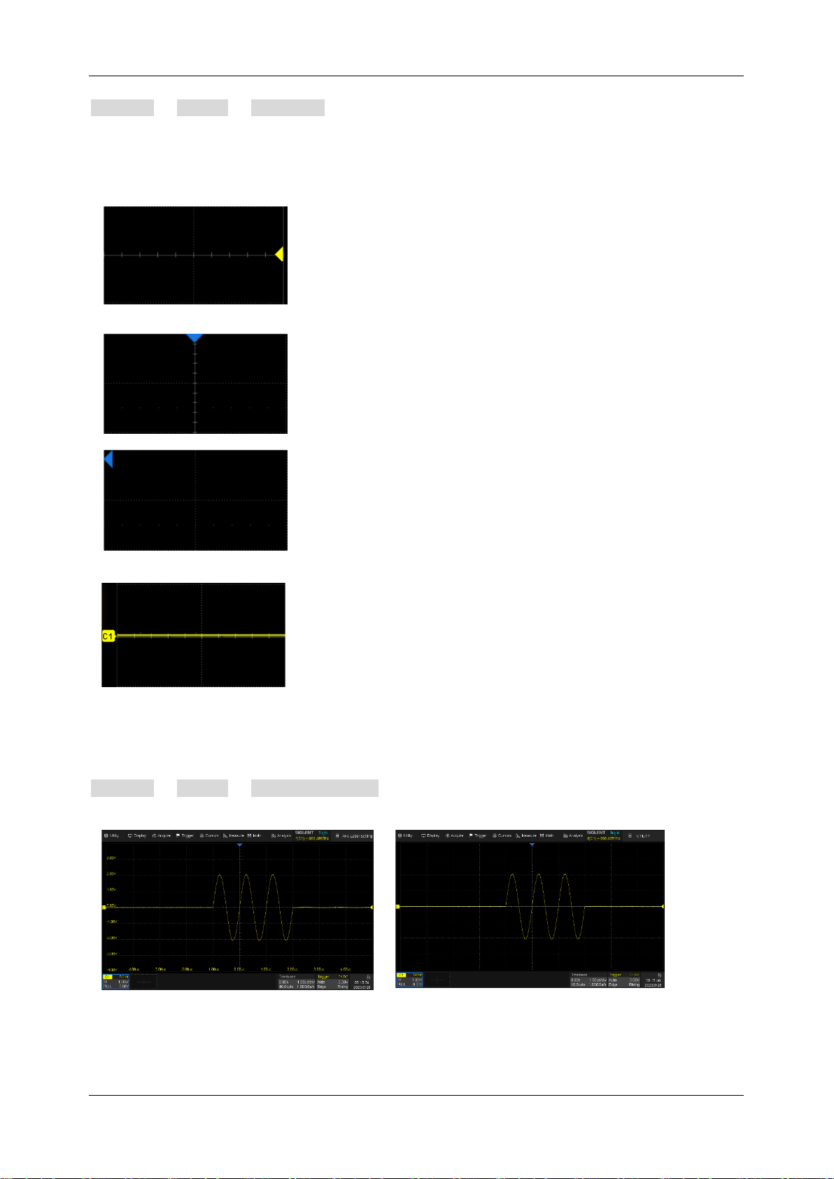
There are multiple indicators on the grid:
Trigger Level Indicator
shows the level where the
waveform triggers on the vertical axis.
Trigger Delay Indicator
locates where the
waveform triggers on the horizontal axis... When
the trigger position is outside the screen, the
direction of the triangle points outside the screen as
well.
Channel Offset Indicator
with a channel number
shows the offset position of the corresponding
channel.
The user can choose to show the axis labels or not by:
Display > Menu > Axis label Setting
Axis label = on
Axis label = off
Page 39
SDS1000X HD Series User Manual
int si glent.com 29
7.4 Channel Descriptor Box
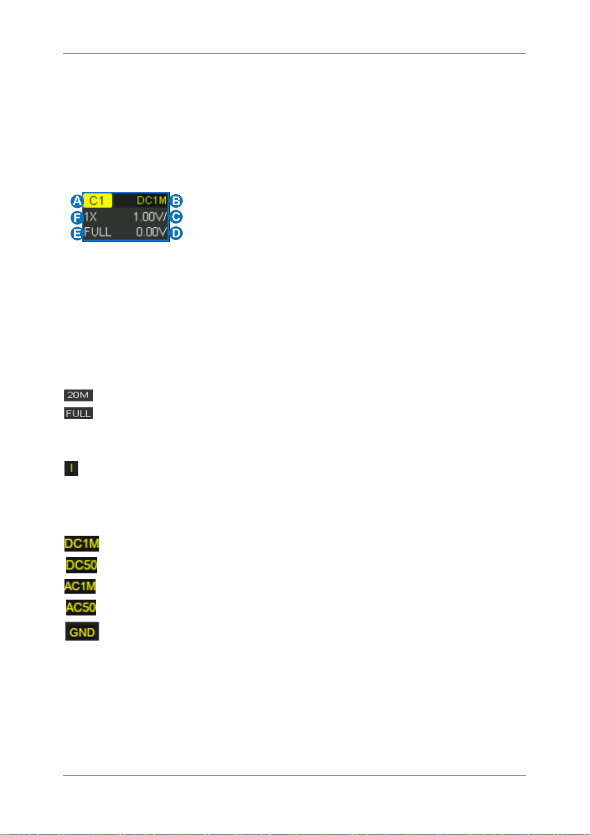
Channel Descriptor boxes include analog channels (Cx), digital channels (D), zoom (Zx), math (Fx),
and reference (Ref). They are located under the grid area, showing the parameters of the
corresponding traces. Touching the boxes creates a dialog box. See chapter “Vertical Setup” for more
details. Below is an example for analog channel 1:
A. Channel Index
B. Coupling and Input Impedance
C. Vertical Scale
D. Vertical Offset
E. Bandwidth Information
F. Probe Attenuation Factor
Bandwidth Information:
The bandwidth information is indicated by the following icons:
: 20 MHz bandwidth limit
: Full bandwidth
Invert Indicator: shows that the current channel is inverted:
: Invert has been turned on
None: Invert has been turned off
Coupling and Input Impedance:
: DC coupling, 1 MΩ impedance
: DC coupling, 50 Ω impedance
: AC coupling, 1 MΩ impedance
: AC coupling, 50 Ω impedance
: Ground
Vertical Scale: The scale of each grid in the vertical direction. For example, when the vertical scale
is 1.00 V/div, the full scale of the oscilloscope is 1.00 V/div * 8 div=8 V.
Vertical Offset: The offset of the channel in the vertical direction. When the vertical offset is 0, the
channel offset indicator is located in the middle of the vertical axis.
Page 40
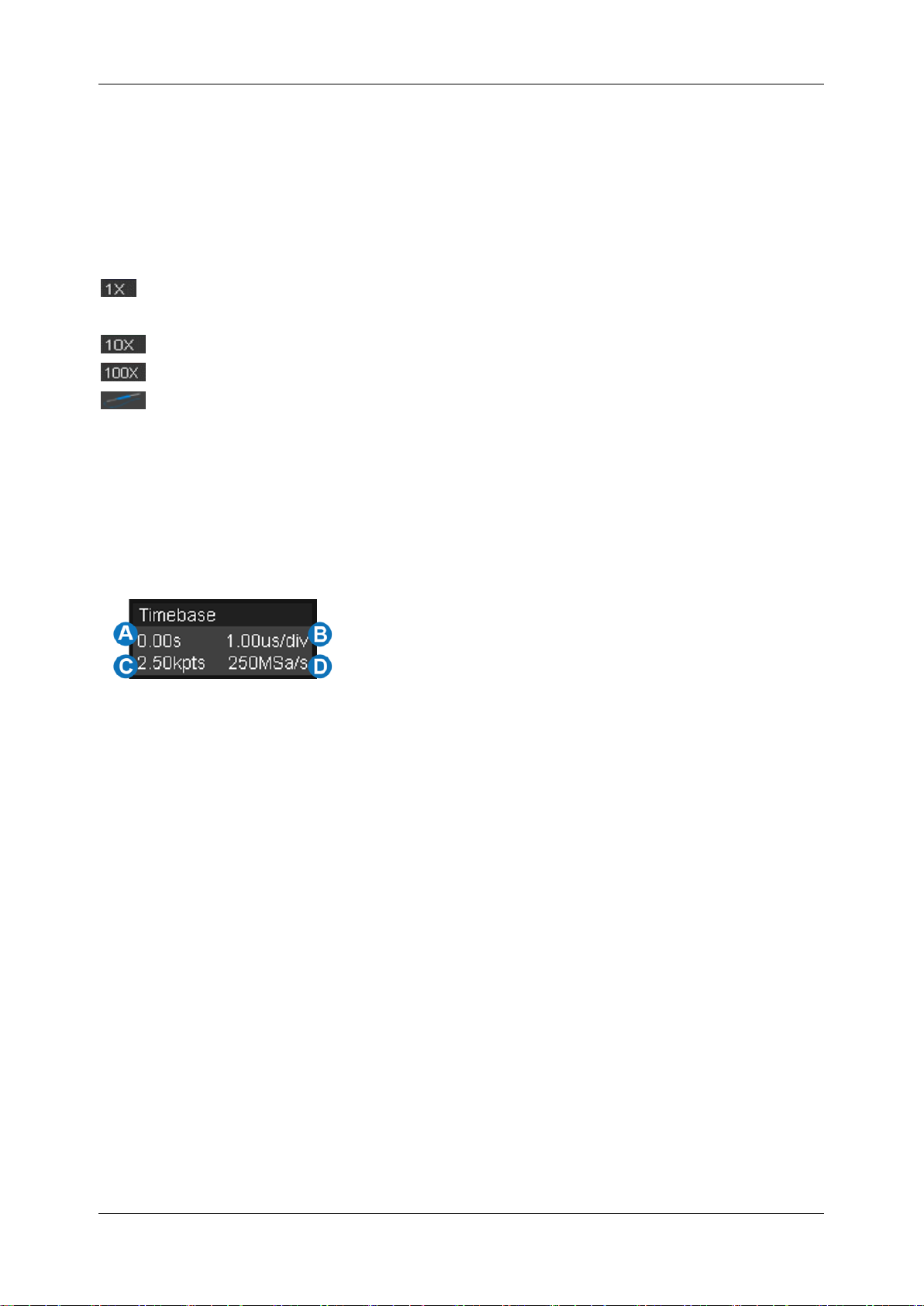
SDS1000X HD Series User Manual
30 i n t . s i g l e n t . c o m
Probe Attenuation Factor: Set the probe attenuation factor to match the actual attenuation of the
probe. The oscilloscope automatically calculates the vertical scale according to the probe attenuation
factor. For example, the vertical scale of the oscilloscope is 100mV/div with 1X attenuation, and 1V/div
if the attenuation factor is changed to 10X. When inserting a standard 10X passive probe with a probe
sense terminal, the oscilloscope will automatically set the factor to 10X.
: 1:1 attenuation, suitable for direct coaxial cable connection or passive probes with 1X
attenuation
: 10:1 attenuation, suitable for general passive probes or active probes with 10X attenuation
: 100:1 attenuation, suitable for some high-voltage probes
: Custom attenuation factor
7.5 Timebase and Trigger Descriptor Boxes
The Timebase Descriptor box shows the parameters of the timebase. See chapter “Horizontal and
Acquisition Setup” for more information.
A. Trigger delay
B. Horizontal scale (timebase)
C. # Samples
D. Sample Rate
Trigger delay: The time offset of trigger position. When trigger delay is 0, the trigger delay indicator
is in the center of the horizontal axis of the grid area.
Horizontal scale: Timebase, the time of each grid in the horizontal direction. For example, if the scale
is 500us/div, the time of each grid is 500 us, and the full-screen time range of the oscilloscope is 500
us/div * 10 div = 5 ms.
# Samples: The number of sample points on the current screen.
Sample Rate: The current sample rate.
The Trigger Descriptor box shows the parameters of the trigger setting. See chapter “Trigger” for
detailed information.
Page 41

SDS1000X HD Series User Manual
int si glent.com 31
A. Trigger source
B. Trigger coupling
C. Trigger mode
D. Trigger level
E. Trigger type
F. Trigger slope
Trigger source
C1~C4:Analog channels
EXT: External trigger channel
EXT/5:5x attenuation of external trigger channel
AC Line: AC mains supply
D0~D15: Digital channels
Trigger coupling: See the chapter "Trigger Coupling" for details.
Trigger mode
Auto: The oscilloscope will sweep without a set trigger. An internal timer triggers the sweep after
a preset timeout period so that the display refreshes continuously. This is helpful when first
analyzing unknown signals. Otherwise, Auto functions the same as Normal when a trigger
condition is found.
Normal: Sweeps only if the input signal meets the trigger condition. Otherwise, it continues to
display the last acquired waveform.
Single: Stops the acquisition and displays the last acquired waveform.
Trigger level: The source voltage level or levels that mark the threshold for the trigger to fire. Trigger
levels specified in Volts normally remain unchanged when the vertical gain or offset is modified.
Trigger type: See the chapter "Trigger" for details.
Page 42
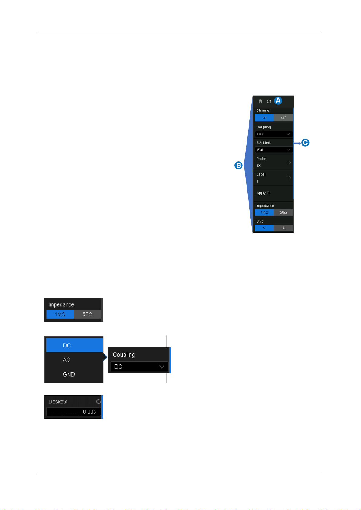
SDS1000X HD Series User Manual
32 i n t . s i g l e n t . c o m
7.6 Dialog Box
The dialog box on the right side of the screen is the main area for setting the parameters of the
selected function.
A. Title bar. Touching the bar can hide the dialog
box, and touching again can open the dialog box.
B. Parameter setting area.
C. Scroll bar. When parameters are more than the
displayed range, the blue scrollbar will be
displayed. By sliding the dialog area up and
down, or rolling the mouse wheel, it can scroll to
the area not displayed.
To Set Parameters
The SDS1000X HD provides a couple of different ways to input/select parameters:
Switch:
Sets parameters with two states, such as to enable or disable a
function. Touch the switch region to change from one state to the other.
List:
Sets parameters with more than two
options, such as coupling mode of channels.
Touch the parameter region, and then select
the expected option from the pop-up list.
Virtual Keypad:
Sets parameters with a numerical value. Touch the
parameter region, and the parameter can be adjusted by the universal
knob on the front panel or by the mouse wheel; touch the region again,
then the virtual keypad appears:
Page 43
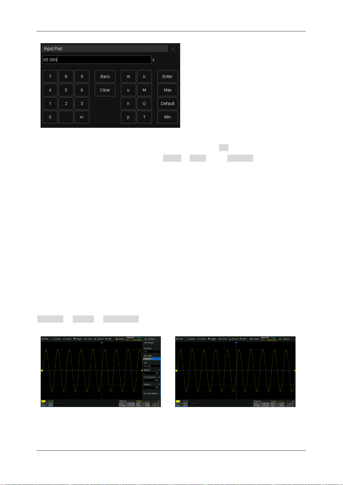
SDS1000X HD Series User Manual
int si glent.com 33
Let’s use the operation of setting the “deskew” of a channel as an example: If the expected value
is 65 ns, input “65” on the virtual keypad, and then choose the units n to complete the operation.
On the virtual keypad, touching the button Max , Min , and Default quickly sets the
parameter to the maximum, minimum, and default values.
Hide the Dialog Box
When the menu style is set to Embedded, the grid area will be compressed horizontally to display the
complete waveform when the dialog box is displayed. After setting the parameters, to achieve the
best waveform display effect, touch the title bar in the upper right corner to hide the dialog box. Touch
it again to recall the dialog box.
When the menu style is set to Floating, it will directly cover part of the grid area when displayed. If
you want to observe the covered area, touch the title bar in the upper right corner to hide the dialog
box. Touch it again to recall the dialog box.
The dialog box can be set to be hidden automatically. When the instrument is not operated beyond
the set time, the dialog box will be automatically hidden. Follow the steps below:
Display > Menu > Hide Menu .
Menu style = Floating, and Dialog box is
displayed
Dialog box is hidden
Page 44
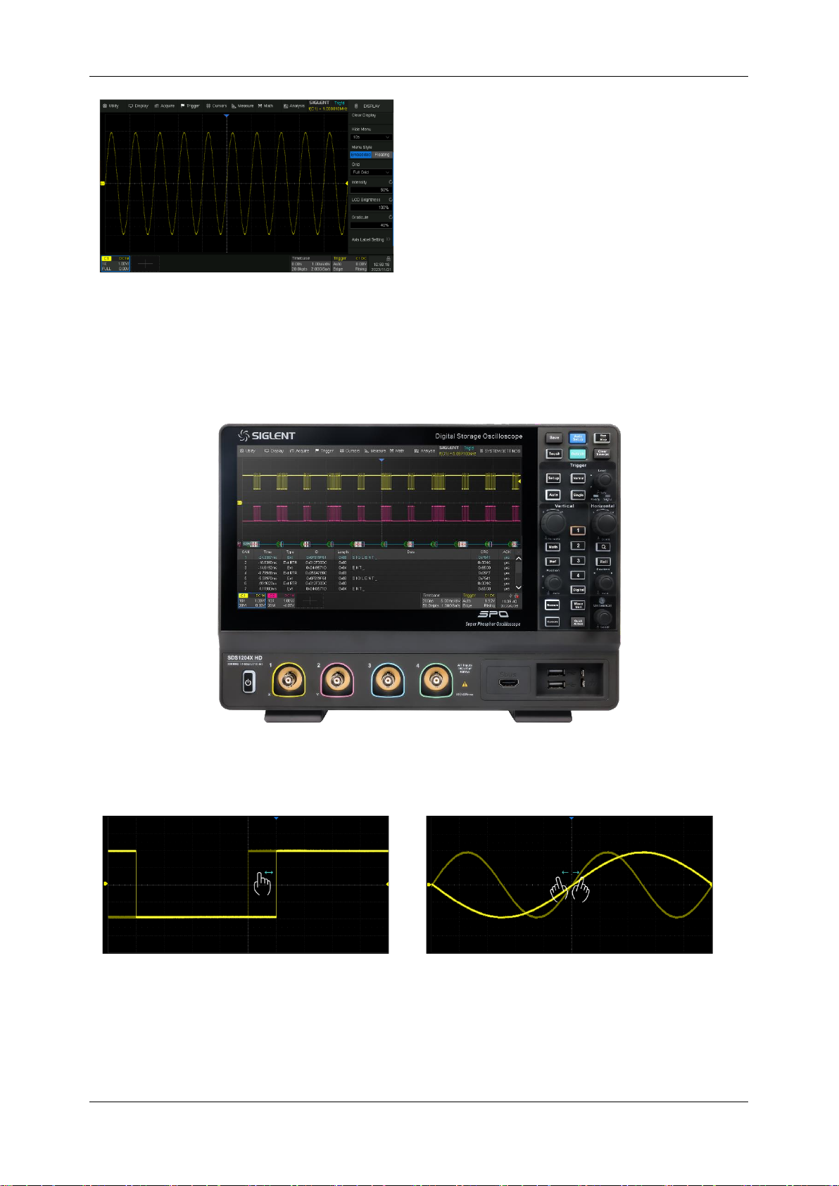
SDS1000X HD Series User Manual
34 i n t . s i g l e n t . c o m
Menu style = Embedded, and Dialog box is
displayed
7.7 Touch Gestures
Waveforms, cursors, and trigger levels can be adjusted.
Drag the waveform left and right to move it
on the horizontal axis
Pinch and spread the waveform horizontally
to re-scale the timebase
Page 45
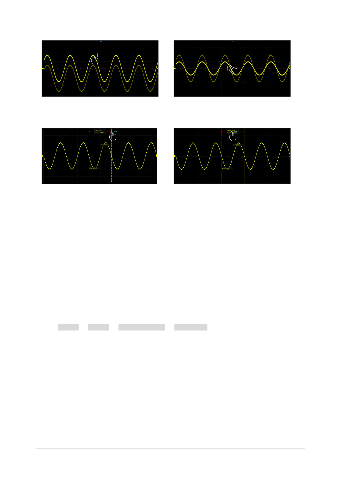
SDS1000X HD Series User Manual
int si glent.com 35
Drag the waveform up and down to move it
on the vertical axis
Pinch and spread the waveform vertically to
re-scale the vertical gain
Touch and drag the cursor to move it
Touch and drag the cursor information region
to move the pair of cursors simultaneously
7.8 Mouse and Keyboard Operation
The SDS1000X HD user interface features mouse control as well as a touch screen. If the
oscilloscope is connected to a USB mouse, you can click on the object with the mouse instead of
touching the object. Similarly, if a USB keyboard is connected, you can use the keyboard to input
characters instead of using the virtual keyboard.
7.9 Choosing the Language
Follow Utility > Menu > System Setting > Language to choose the language.
See the section “Language” for details.
Page 46
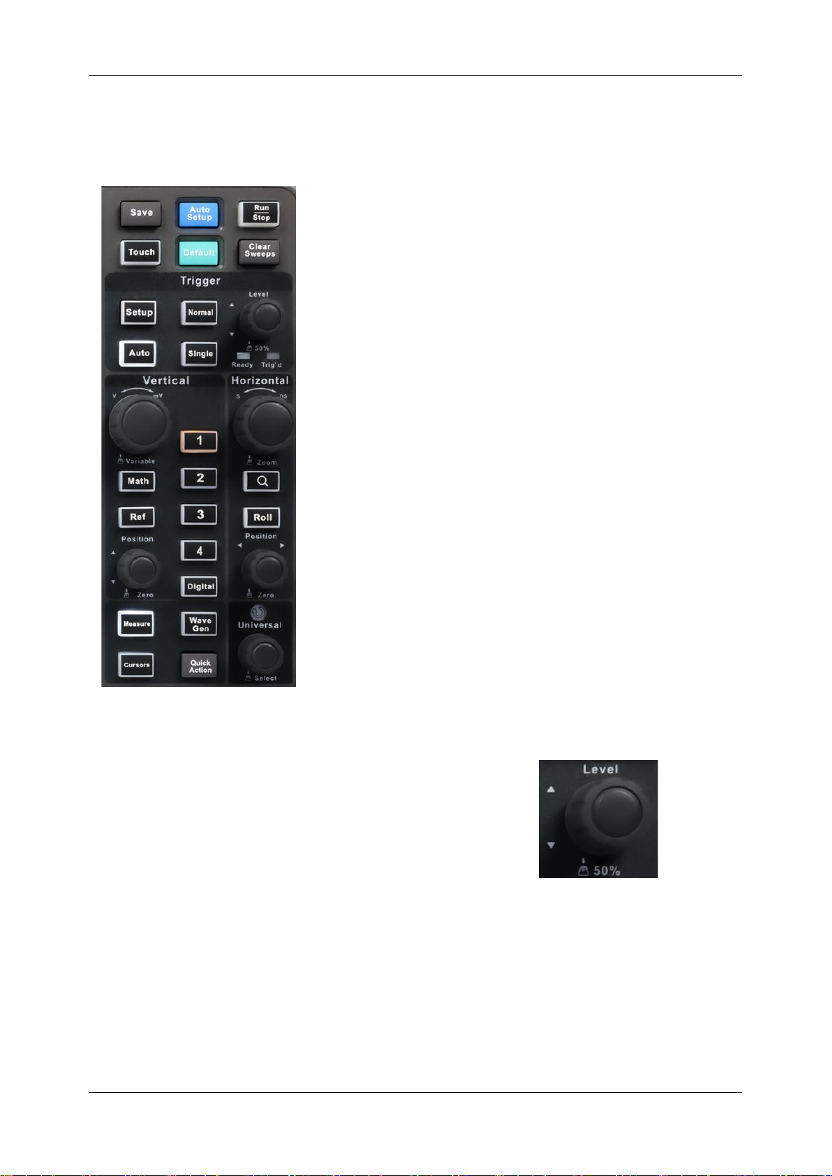
SDS1000X HD Series User Manual
36 i n t . s i g l e n t . c o m
8 Front Panel
8.1 Overview
The front panel is designed to operate the basic functions
without having to open the software menu. Most of the front
panel controls duplicate functionality available through the
touch screen display but the operation is more quickly
achieved.
All the knobs on the front panel are multi-function. They
can be pushed as well as rotated. Pushing a knob quickly
recalls a specific function, which is indicated by the
silkscreen near the knob.
Page 47
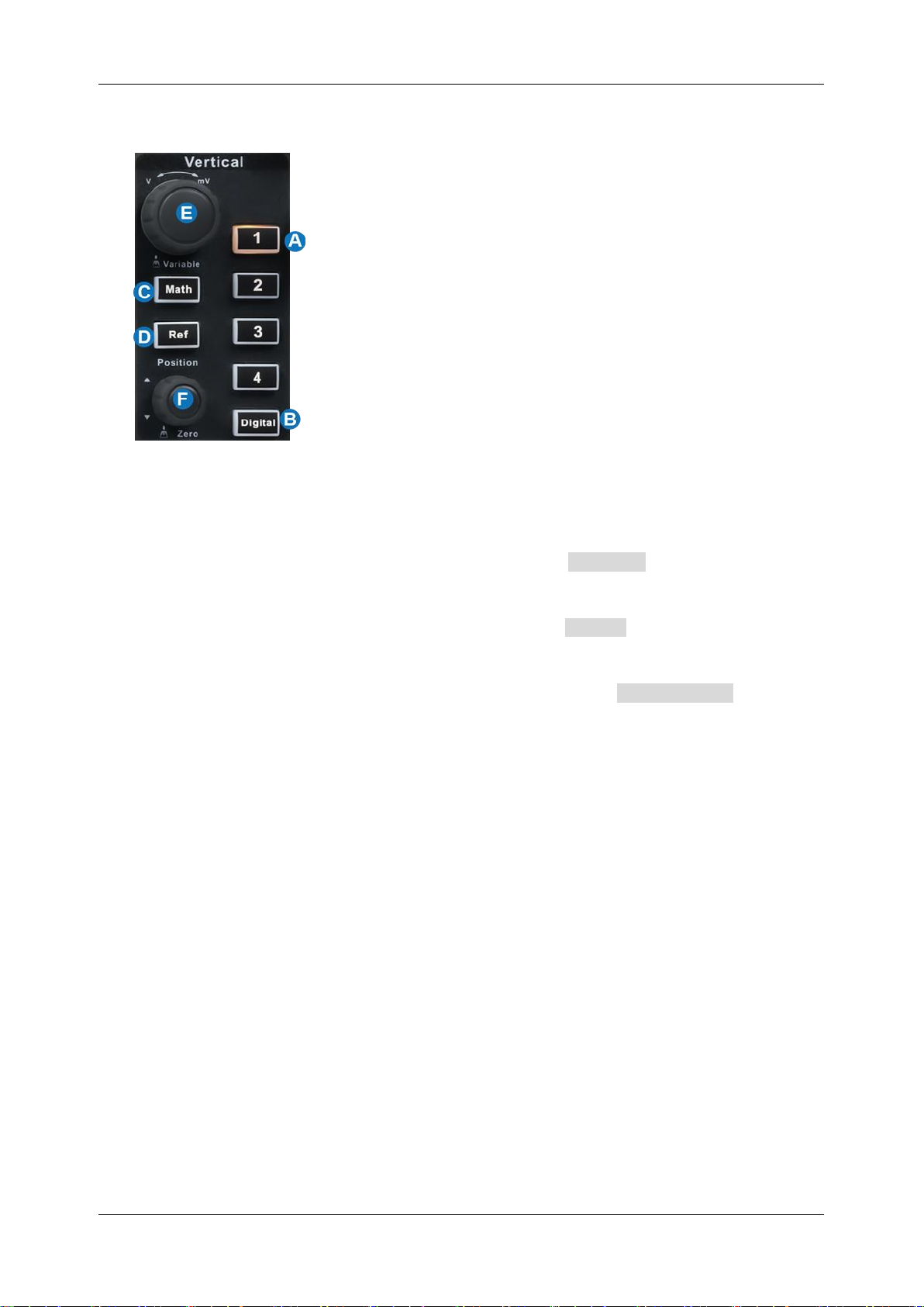
SDS1000X HD Series User Manual
int si glent.com 37
8.2 Vertical Control
A. When a channel is disabled, push its channel button to turn it on. When a channel is turned on
but not activated, push the button to activate it. When the channel is turned on and activated,
push the button to disable it.
B. Press the button to turn on the digital channel and open the DIGITAL dialog box. Press again
to turn off the digital channels.
C. Press the button to turn on the math function and open the MATH dialog box. Press again to
turn off the math function.
D. Press the button to turn on the reference function and open the REFERENCE dialog box.
Press again to turn off the reference function.
E. Analog channels (C1-C4), digital channels (D), math (F1-F4), and references (Ref) share the
same vertical knob. Rotate the knob to adjust the vertical scale (volt/div) of the activated trace.
Push to alternate between coarse and fine adjustments. When the digital channel is active, rotate
the knob to change the selected digital channel.
F. Analog channels (C1-C4), digital channels (D), math (F1-F4), and references (Ref) share the
same offset knob. Rotate the knob to adjust the DC offset or vertical position of the activated
trace. Push to set the offset to zero. When the digital channel is active, rotate the knob to change
the position of the selected digital channel.
Page 48
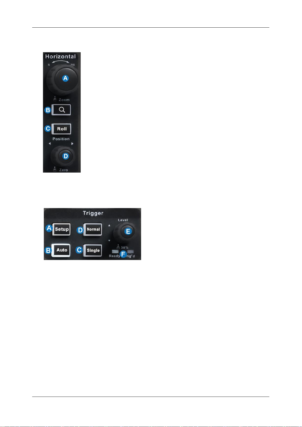
SDS1000X HD Series User Manual
38 i n t . s i g l e n t . c o m
8.3 Horizontal Control
A. Rotate to adjust the horizontal scale (time/div); push to enable
Zoom; push again to switch between the main window and zoom
window.
B. Push to enable Zoom. Push again to exit Zoom mode.
C. Push to enable horizontal Roll; push again to exit Roll mode. At
time-base settings larger than 50 ms/div, it is recommended to
set the oscilloscope to Roll mode so that the waveform is
displayed in real-time.
D. Rotate to adjust trigger delay; push to set trigger delay to zero.
8.4 Trigger Control
A. Opens the trigger setup dialog box
B. Auto mode: Triggers after a preset period if no valid trigger occurs
C. Single mode: Triggers once when all conditions are met
D. Normal mode: Triggers repeatedly when all conditions are met
E. Trigger level adjustment: Push to set the level to 50% of the waveform
F. Trigger status LED, Ready and Trig'd
Page 49
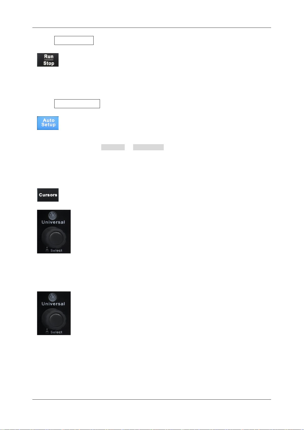
SDS1000X HD Series User Manual
int si glent.com 39
8.5 Run/Stop Button
Press the button to switch the acquisition state between Run and Stop. When the
state is Run, the button is illuminated in green. When the state is Stop, the button
is illuminated in red.
8.6 Auto Setup Button
Auto Setup forces the oscilloscope to automatically set the vertical scale,
horizontal scale, and trigger level according to the input signal to get optimum
waveform display. An Auto Setup operation can also be performed by following
the steps Acquire > Auto Setup .
8.7 Cursors Control
Push the button to open the cursors setup dialog box.
Rotate the knob to move the selected cursor; push to select a different cursor.
8.8 Universal Knob
When the parameter setting area is highlighted, the Universal Knob can be used
to adjust the parameter. Press the knob to select an option from the list. The
default function of the Universal Knob is to adjust the intensity of the waveform
traces.
Page 50
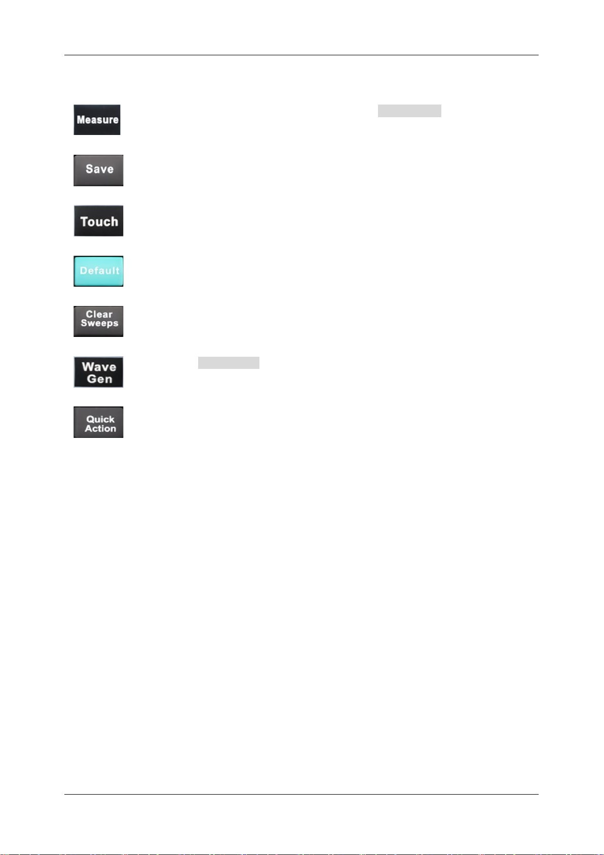
SDS1000X HD Series User Manual
40 i n t . s i g l e n t . c o m
8.9 Other Buttons
Enables / Disables measurements and recalls the MEASURE dialog box.
Performs a quick screenshot save or saves the currently save type file to the storage
path. See the section “Save Button” for details.
Enables/Disables the touch screen. The LED on the button lights to indicate that the
touch screen is working.
Resets the oscilloscope to the default configuration.
Clears the data or displays in multiple sweeps, including display persistence,
measurement statistics, average sweeps, and Pass/Fail statistics.
Recalls the Wave Gen dialog box. The LED on the button lights to indicate the
output of the AWG is enabled.
The preset functions can be called quickly through this button. See the section "Quick
Action" for details
Page 51
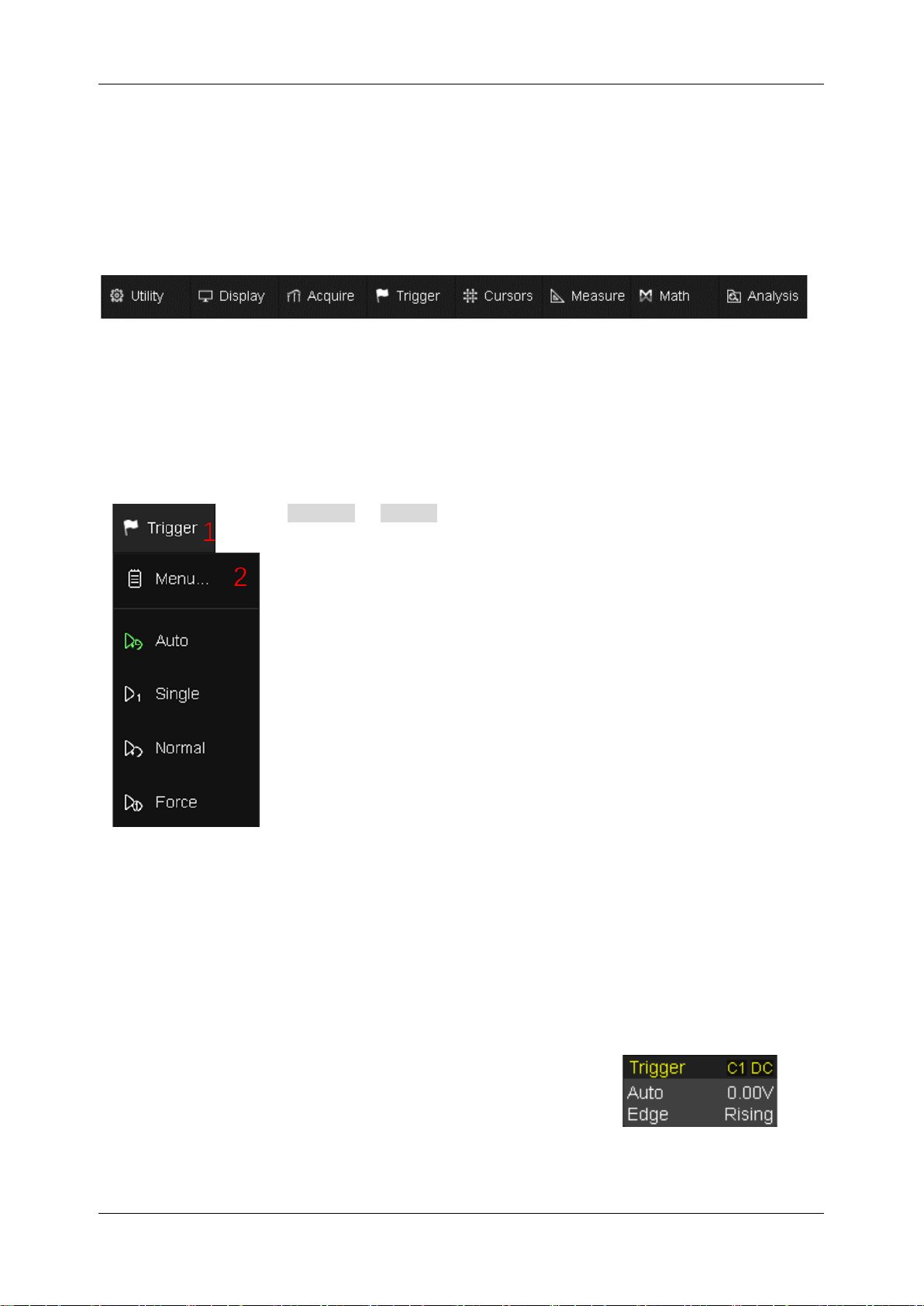
SDS1000X HD Series User Manual
int si glent.com 41
9 Multiple Approaches to Recall Functions
The oscilloscope can recall functions through different approaches.
9.1 Menu Bar
If you are familiar with common computer programs, you may first choose to access a function by the
drop-down menu from the menu bar at the top of the display.
For example, to open the trigger setup dialog box, you can follow the steps below:
Trigger > Menu
The operations can be completed either by touch or by
mouse clicks.
9.2 Descriptor Box
For the setup of channels, math, ref, timebase, and trigger, there are dialog boxes at the bottom of
the display. For the introduction of the descriptor box, see sections “Channel Descriptor Box” and
“Timebase and Trigger Descriptor Box”.
For the example above, touch the trigger descriptor box and the
trigger setup dialog box will be activated.
Page 52

SDS1000X HD Series User Manual
42 i n t . s i g l e n t . c o m
9.3 Shortcut Button on the Front panel
Most of the functions of the oscilloscope can be recalled directly by the shortcut buttons on the front
panel. See the chapter "Front Panel" for details.
To open the trigger setup dialog box, press the Setup button in
the trigger control area on the front panel.
Page 53

SDS1000X HD Series User Manual
int si glent.com 43
10 Quickly Capture the Signal
This is an example of how to acquire a signal quickly. In this example, we assume the signal is
connected to channel 1 and channel 1 is turned off.
First, press the channel 1 button to turn on channel 1. The LED on the button
lights and the descriptor box of channel 1 is displayed at the bottom of the screen.
Second, press the Auto Setup button. The oscilloscope will automatically
adjust the vertical scale, horizontal scale, and trigger level according to the input
signal to get an optimum waveform display.
Auto Setup will not work on all signal types, especially time-varying bursts or slow signals (< 100 Hz).
If Auto Setup cannot achieve desired settings, manually adjustment of the vertical, horizontal, and
trigger systems is preferred. See the chapters "Vertical Setup", "Horizontal and Acquisition Setup"
and "Trigger" for details.
Page 54
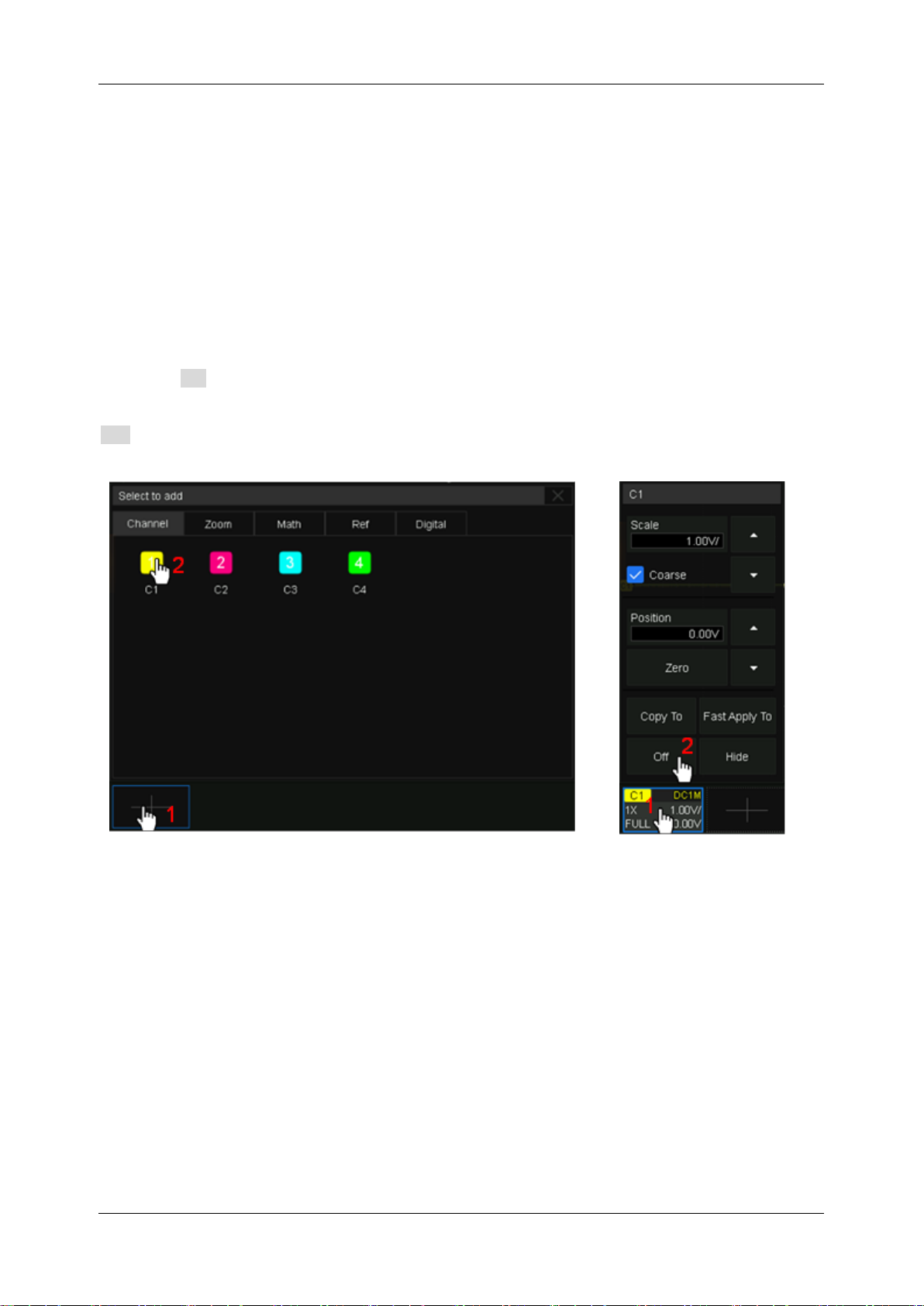
SDS1000X HD Series User Manual
44 i n t . s i g l e n t . c o m
11 Vertical Setup
11.1 Turn on/off a Channel
From the Front Panel
When a channel is disabled, push its channel button to turn it on. When a channel is turned on but
not activated, push the button to activate it. When the channel is turned on and activated, push the
button to disable it.
From the Touch Screen
Touch the + button and then select the expected channel to turn it on, and its channel descriptor
box and a dialog box will appear on the display. Touch the channel descriptor box and then touch the
Off button to disable it.
Turn on C1
Turn off C1
Page 55
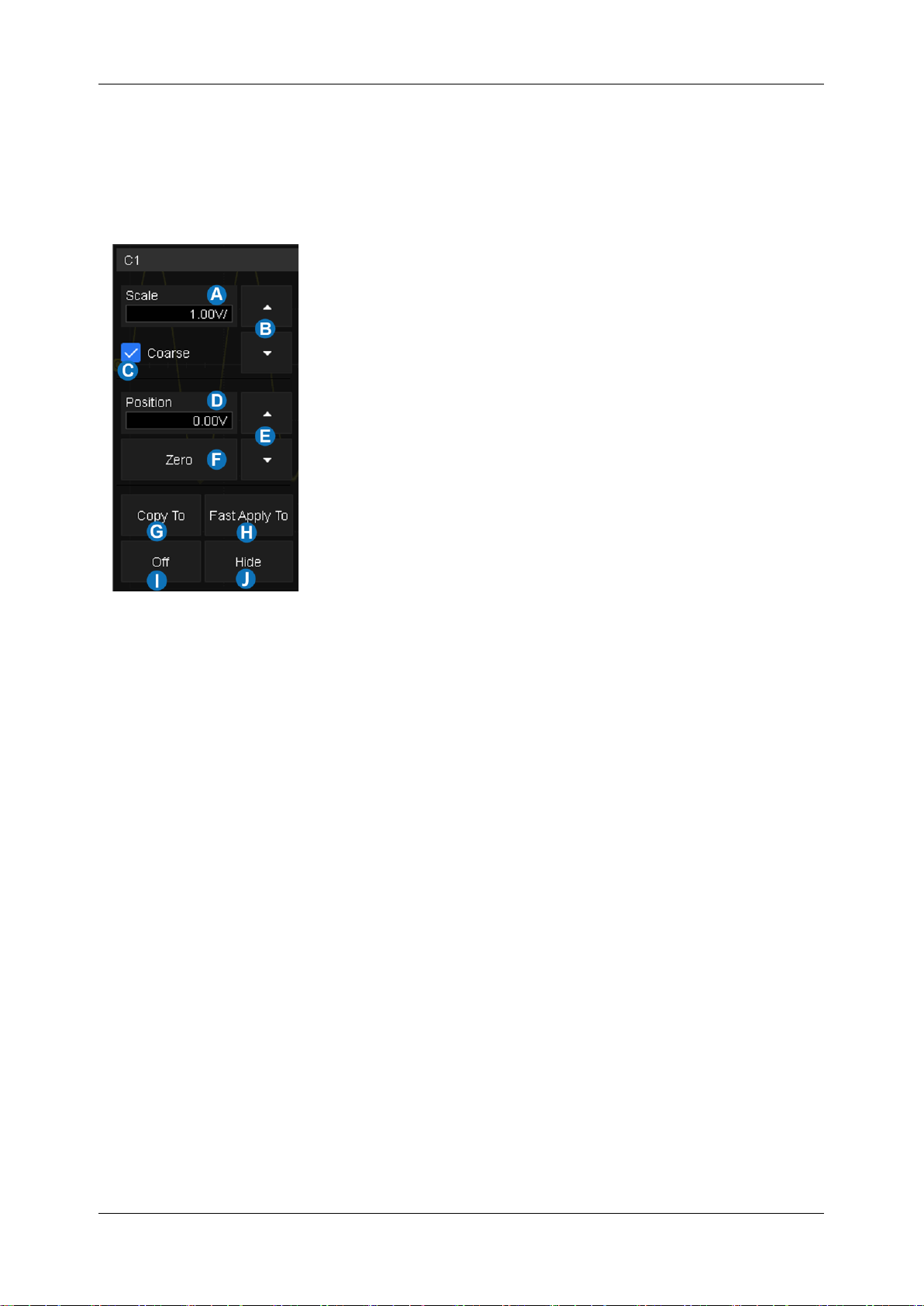
SDS1000X HD Series User Manual
int si glent.com 45
11.2 Channel Setup
Touch the channel descriptor box, a quick dialog will pop up. Vertical scale and offset can also be set
from this dialog box.
A. Touch the region to set the vertical scale with the
universal knob or virtual keypad
B. ▲ to increase the vertical scale and ▼ to decrease
C. Check to coarsely adjust the vertical scale and uncheck
to enable fine adjustment
D. Touch the region to set the offset with the universal knob
or virtual keypad
E. ▲ to increase the offset and ▼ to decrease
F. Set the offset to zero
G. Copy the setting of the current channel to another
channel
H. Quickly apply the current channel as the source of a
specified operation (Trigger, FFT, Simple Measure,
Cursor, Search, Counter and Wave Gen)
I. Disable the channel
J. Hide the trace
The vertical scale can be adjusted in coarse or fine mode. Fine mode can reach the full-scale display
as close as possible, which gets the best measurement accuracy in the vertical direction. The
oscilloscope automatically switches to fine mode when the vertical scale is controlled by touch
gestures.
Activating a channel recalls the channel dialog box, displaying more parameters:
Page 56
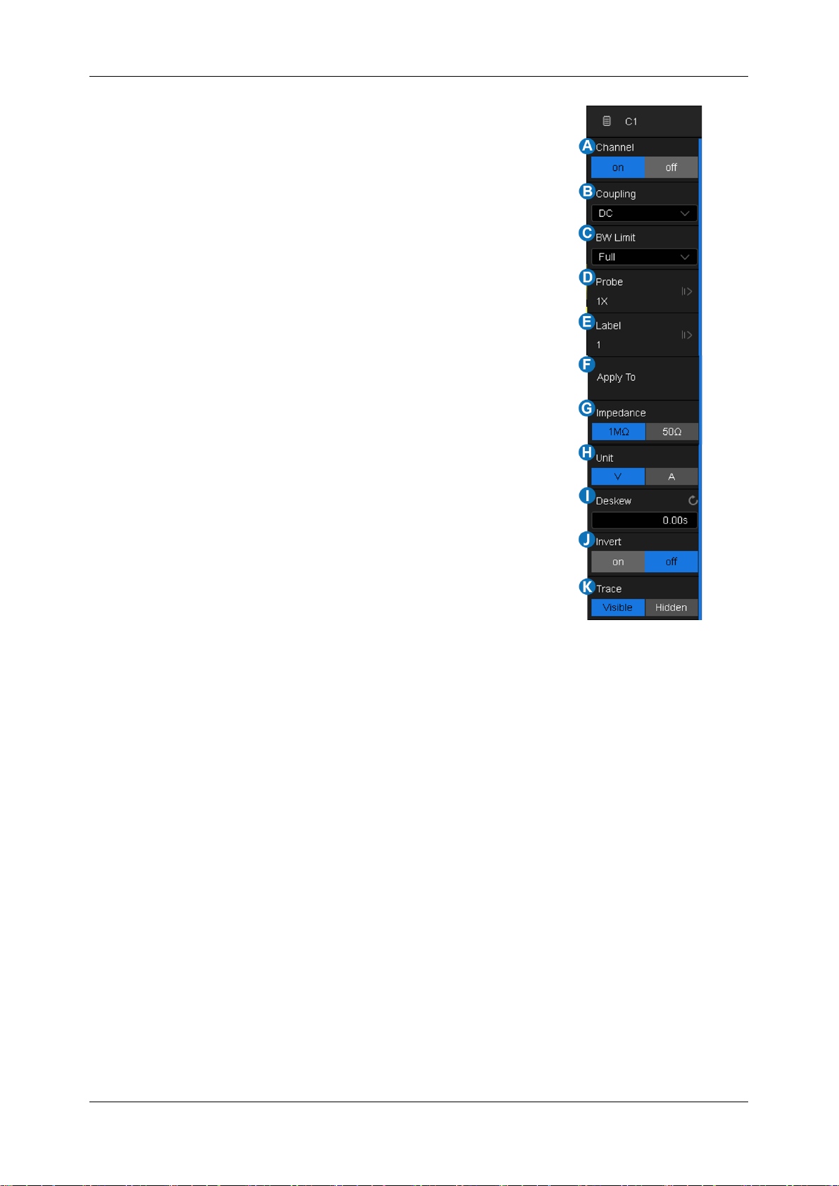
SDS1000X HD Series User Manual
46 i n t . s i g l e n t . c o m
A. Turn channel on/off
B. Coupling (DC, AC or GND)
C. Bandwidth limit (Full or 20 MHz)
D. Probe settings including attenuation (1X, 10X, 100X or
custom) and probe check
E. Set the label text. Click to recall the label setting. Users can
customize the text and display of the label
F. Quickly apply a specified operation (Trigger, FFT, Simple
Measure, Cursor, Search, Mask Test, Counter and Wave
Gen) to the current channel
G. Impedance
H. Units for the channel
I. Deskew
J. Enable/disable invert
K. Trace visible/hidden
Coupling
DC: All of the input signal frequency components are passed to the display.
AC: The signal is capacitively coupled. DC signal components are rejected. See the datasheet
for details of the cut-off frequency.AC coupling is suitable for observing AC signals with DC offset,
such as power ripple.
GND: The channel is grounded by an internal switch. GND coupling is used to observe the zero
offset error of the analog channels or determine the source of noise in the waveform (from signal
or from oscilloscope itself).
Bandwidth Limit
Full bandwidth passes through signals with high-frequency components, but it also means that noise
with high-frequency components can pass through. When the frequency component of the signal is
very low, better signal-to-noise ratios (SNR) can be obtained by turning on a bandwidth limit. The
SDS1000X HD provides two hardware bandwidth limit options: Full or 20 MHz.
Page 57
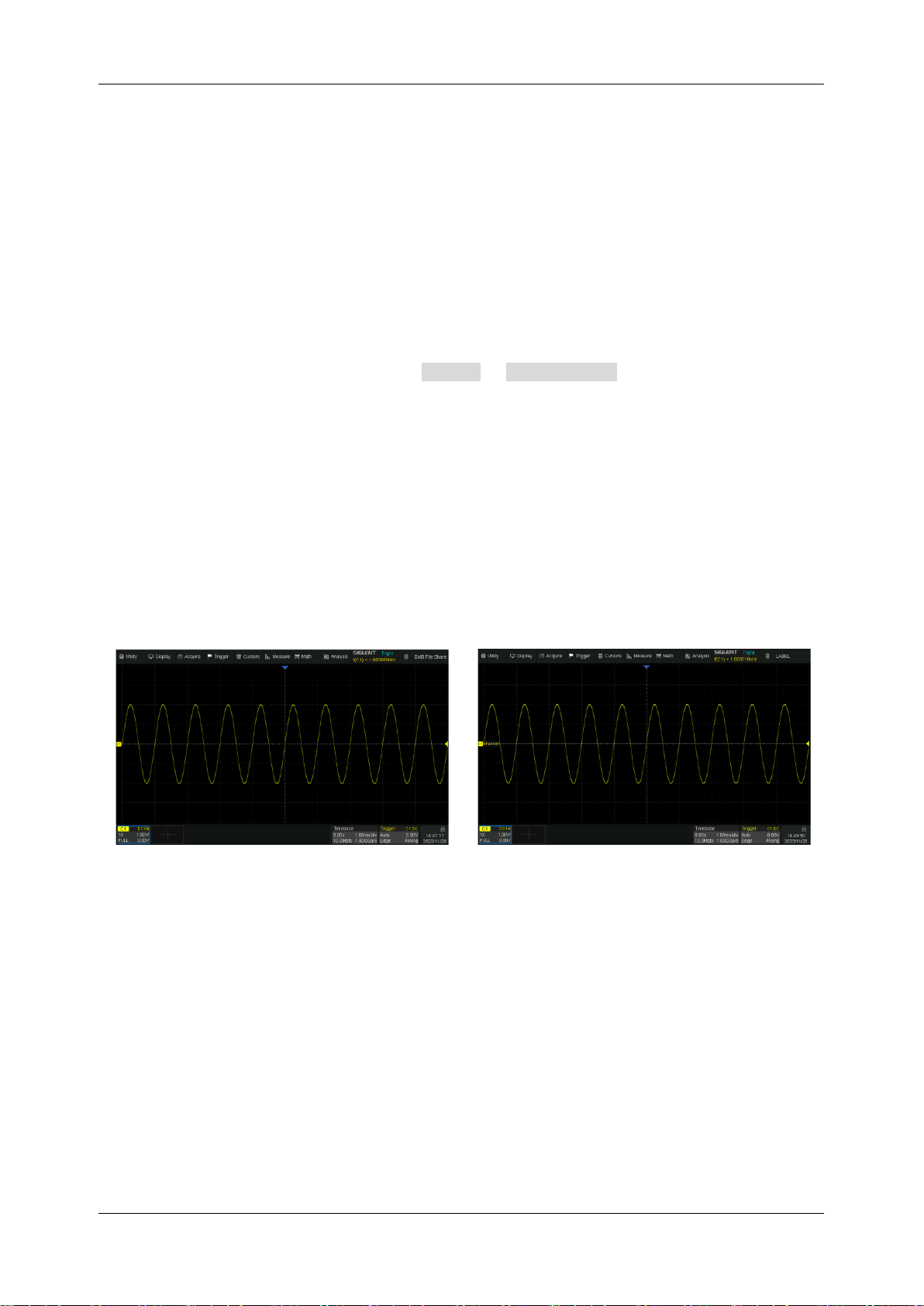
SDS1000X HD Series User Manual
int si glent.com 47
Probe Settings
The SDS1000X HD provides 1X, 10X, 100X and custom probe attenuation factor options. The custom
values can be between 10-6~106. The oscilloscope will automatically convert the vertical scale
according to the current probe attenuation factor. For example, the vertical scale of the oscilloscope
under 1X attenuation is 100 mV/div, and the vertical scale will be automatically set to 1 V/div if the
probe attenuation is changed to 10X. If a standard probe with a readout terminal is connected, the
oscilloscope will automatically set the probe attenuation to match the probe.
The Probe Check option is provided to quickly check if the probe is correctly compensated. Connect
the probe as in section “Probes” and touch Probe > Probe Check , then operate according to
the prompt.
Label
Users can set the label text for channels. Open the label setting dialog box to select the source,
customize the label text, and set the display. The source can be C1~C4, Math, and RefA~RefD. The
length of the label is limited to 20 characters. The characters beyond this length will not be displayed.
When the “Display” option is set to “on”, the label will be displayed on the right side of the channel
offset indicator.
The labels are hidden
The labels are displayed
Apply to
With this setting, some common functions such as Trigger, FFT, Simple Measure, Cursor, Search,
Mask Test, Counter and Wave Gen can be quickly applied to the selected channel. Once a function
is specified, it will switch directly to the function menu and automatically set that channel as the source.
Impedance
1 MΩ: When a passive probe with high impedance is connected, the impedance must be set to
1 MΩ, otherwise the signal will not be detected.
Page 58
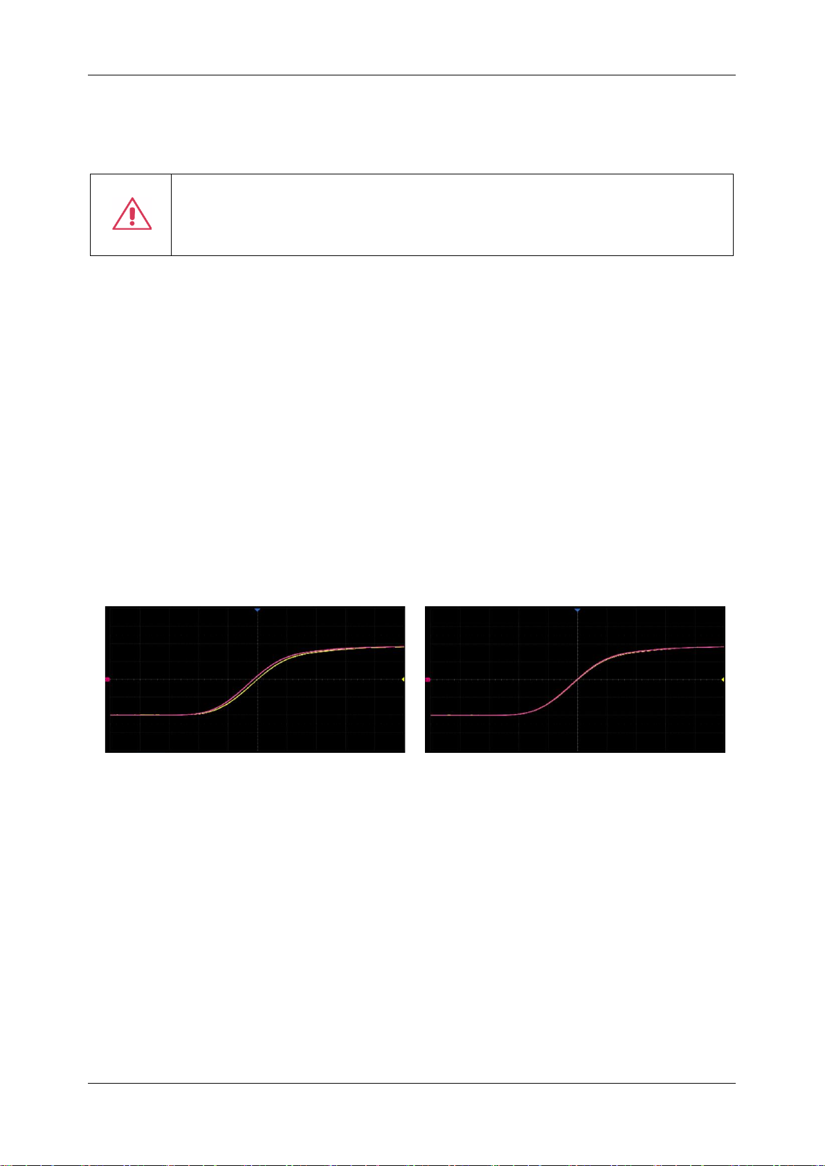
SDS1000X HD Series User Manual
48 i n t . s i g l e n t . c o m
50 Ω: Suitable for high-frequency signals transmitted through 50 Ω coaxial cables or active
probes. This can minimize the amplitude distortion caused by impedance mismatching.
Warning: The 50 Ω input setting is not a high-power input. Damage can occur if the
input exceeds the published specifications. See the datasheet for more
details.
Unit
Voltage unit "V" or current unit "A”. When using the current probe, the unit should be set to "A".
Deskew
Due to the skew between channels, cables, or probes, the delay of signals passing through different
measurement paths may be inconsistent. For example, two coaxial cables with a 1-inch difference in
length could introduce a skew of more than 100 ps. In some scenarios (e.g. measuring the setup/hold
time between clock and data), it may be necessary to compensate for the skew between channels.
The method of compensation: Probe the same signal simultaneously using two channels (including
the cables or probes that you intend to use for measurements) and adjust the deskew parameter of
one channel until the waveforms of the two channels observed on the screen coincide horizontally.
Before deskew
After deskew
Note: When the channel with deskew compensation is the trigger source, the trigger delay indicator
does not change as the deskew value changes.
Invert
When invert is enabled, the waveform is rotated 180 degrees around earth potential (0 Volts).
Page 59
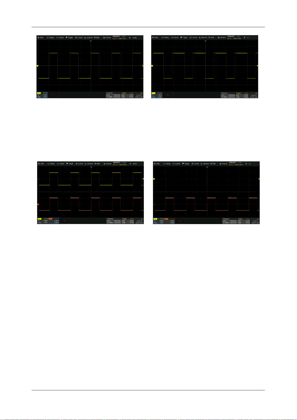
SDS1000X HD Series User Manual
int si glent.com 49
Before invert
After invert
Trace
When the trace is hidden, the channel waveform is no longer displayed on the screen, while the
acquisition is still running in the background.
Trace visible
Trace hidden
Page 60
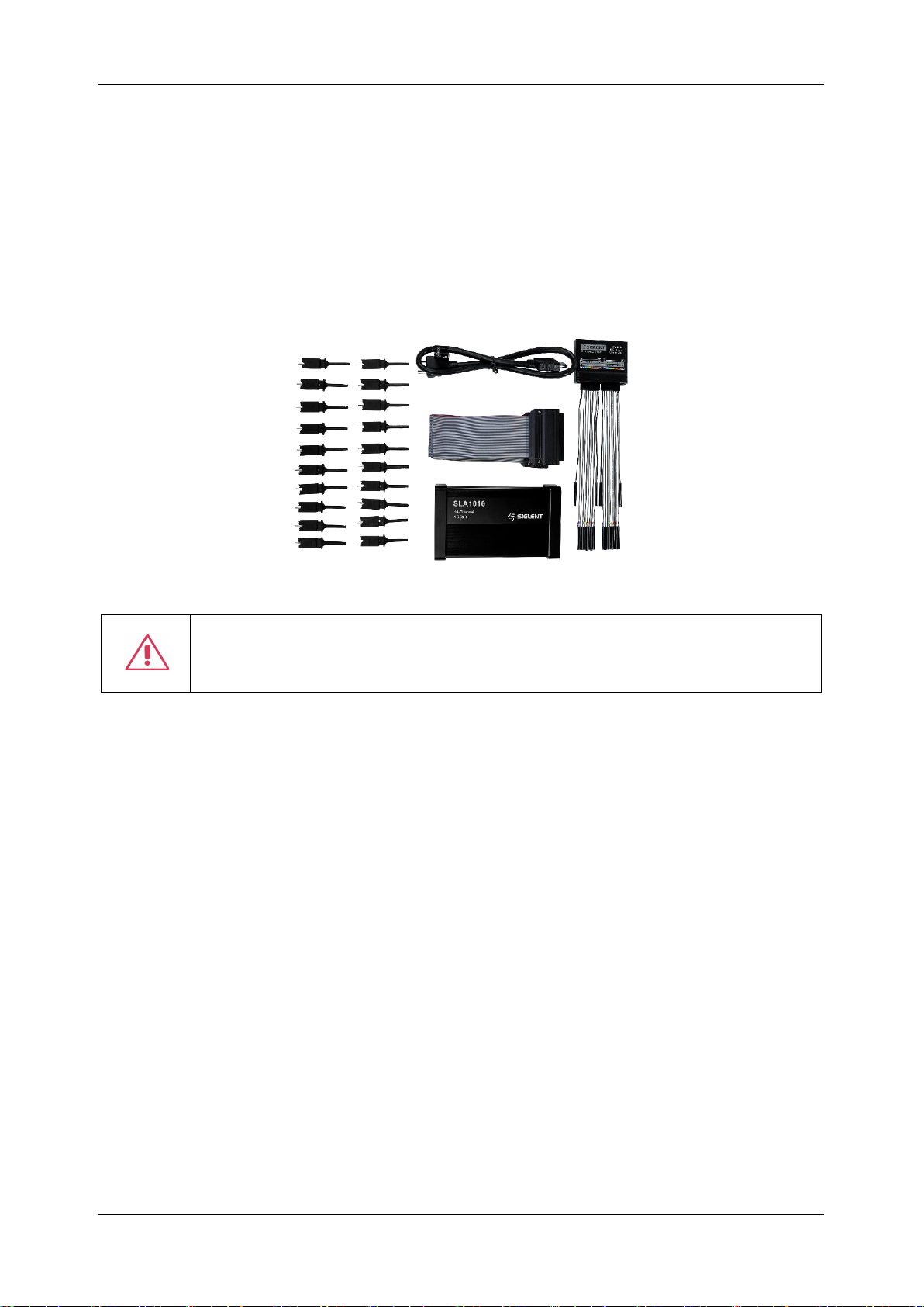
SDS1000X HD Series User Manual
50 i n t . s i g l e n t . c o m
12 Digital Channels
12.1 Overview
SLA1016 Probe
The SLA1016 is a logic probe designed to monitor up to 16 digital signals at once. The 16 digital
channels are separated into two groups and each group has its threshold, making it possible to
simultaneously view data from different logic families.
Note: To avoid personal injury or damage to the logic probe and any associated
equipment, the following safety precautions should be noted.
The equipment shall be used only for the purposes specified by the manufacturer. The
SLA1016 probe is used only for SIGLENT's special series of oscilloscopes. Protection mechanisms
can be compromised if the way the devices connected by the SLA1016 are not used for their intended
purpose.
Connect and disconnect correctly. Excessive bending can damage the cable.
Do not use equipment in humid or explosive environments.
Only used indoors. The SLA1016 is designed to be used indoors and should only be operated in a
clean, dry environment.
Do not use the equipment when you suspect a problem. Do not use the SLA1016 if any parts are
damaged. Maintenance work shall be performed by maintenance personnel with appropriate
qualifications.
Keep product surface clean and dry.
SDS1000XHD-16LA Option
The software option adds the following functions to the oscilloscope:
Digital channel acquisition and analysis
- Acquire and analyze the signals connected to the
Page 61
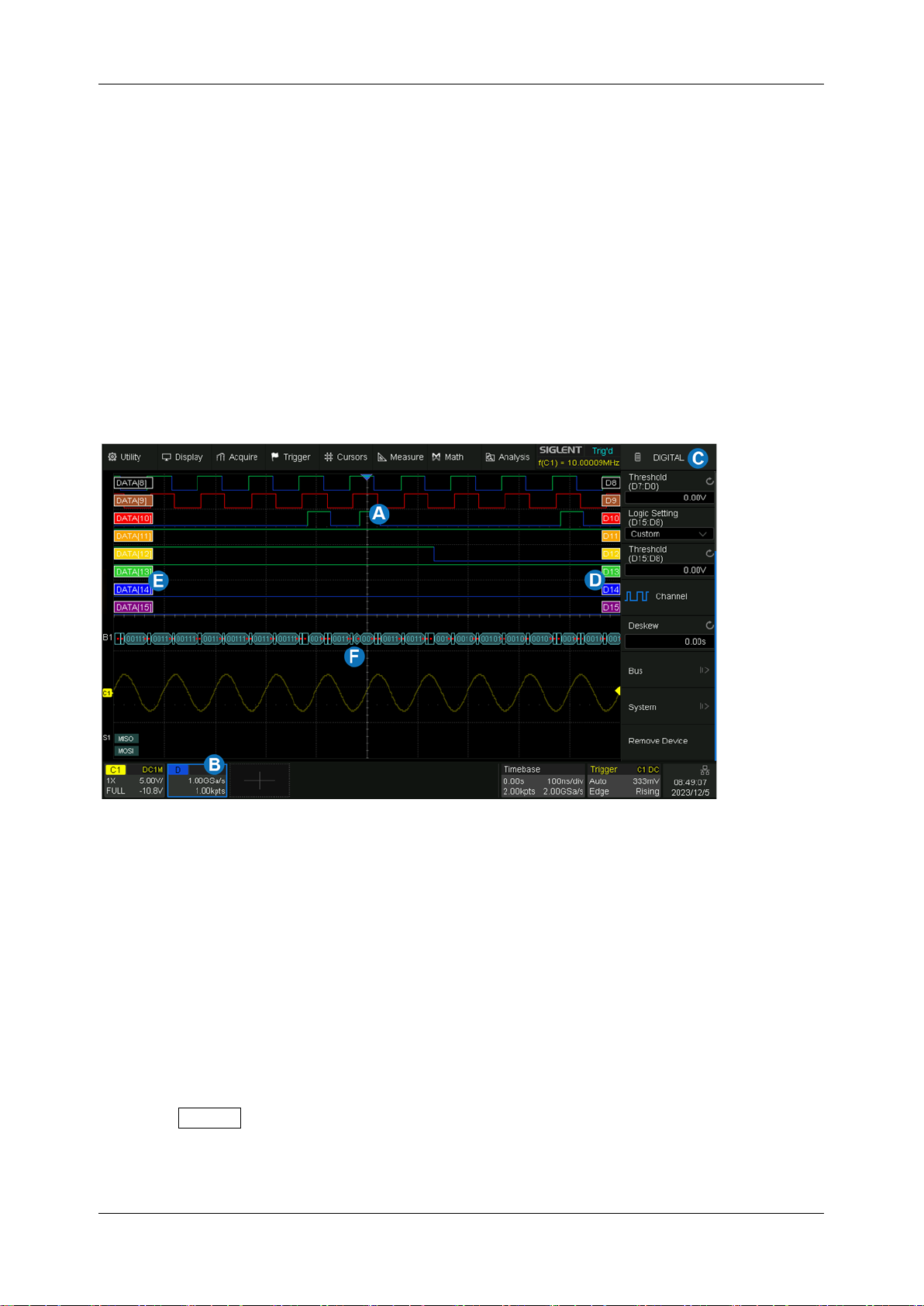
SDS1000X HD Series User Manual
int si glent.com 51
digital logic probe, including waveform display, save, parameter measurement, etc.
Trigger on a digital channel
- Trigger with the digital channel as the trigger source, isolating
events of interest.
Decode on a digital channel
- Serial protocol decoding of a digital channel requires the
installation of the serial decode option.
12.2 Enable/Disable the Digital Channels
Turning on or off the digital channels is similar to analog channels. Digital data can be stored as
waveform files. Horizontal cursors and most horizontal measurements also apply to digital waveforms.
A. Digital channel waveform display, which shares the same grid area with the analog channels.
B. Digital channel descriptor box.
C. Dialog box.
D. Digital channel indicators. Up to 16 digital channels are organized in two groups with different
thresholds: D15~D8 and D7~D0. Every channel can be turned on or off individually.
E. Labels can be set to data, address or custom characters.
F. Digital bus
From the Front Panel
Press the Digital button on the front panel to turn on digital channels and display the waveforms.
Press again to turn it off.
Page 62
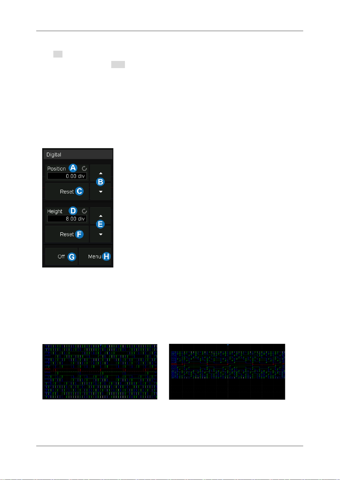
SDS1000X HD Series User Manual
52 i n t . s i g l e n t . c o m
From the Touch Screen
Click + at the bottom of the display and select the “Digital” to turn it on. Click the digital channel
descriptor box, and select Off on the pop-up menu to turn it off. Refer to the operation in the
chapter “Vertical Setup” for details.
12.3 Digital Channel Setup
Touch the digital descriptor box, then the quick menu of digital channel settings pops up above the
descriptor box. In the menu height and position of digital channels can be set:
A. Upper position limit of the digital channel display area.
Use the universal knob or virtual keypad to set it.
Decrease the height to provide more adjustment area.
B. ▲ to increase position and ▼ to decrease the channel
location.
C. Reset the position to the default value.
D. The range in height of the digital channels display
area. Use the universal knob or virtual keypad to set
it. If the display height covers all of the available
divisions, there will not be room to adjust the position.
E. ▲ to increase and ▼ to decrease the number of
divisions occupied by the digital channels.
F. Reset the height to the default value.
G. Turn off the digital channels.
H. Open the digital dialog box on the right side.
Height=8div, Position=0div
Height=4div, Position=1div
Page 63
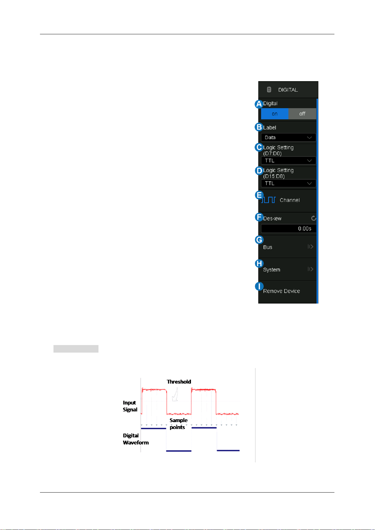
SDS1000X HD Series User Manual
int si glent.com 53
The quick menu only covers the height range and position of the digital channels display area. More
settings can be found in the dialog box.
A. Turn on/off the digital channels.
B. Labels can be set to data, address, or custom characters.
C. Logic threshold of D7~D0. The oscilloscope will automatically
set the threshold according to the specified logic family, or the
user can set the threshold manually using the Custom option.
D. Logic threshold of D15~D8.
E. Set the channels to be displayed.
F. Deskew setting, the same as setting analog channels.
G. Bus setting.
H. System information and firmware upgrade.
I. Remove SLA1016 probe.
Logic Threshold Setting
The threshold level determines how the input signal is evaluated. The threshold level can be set in
the Logic Setting . The input voltage less than the threshold is recognized as a '0', and the input
voltage greater than the threshold is recognized as a ‘1’.
Page 64
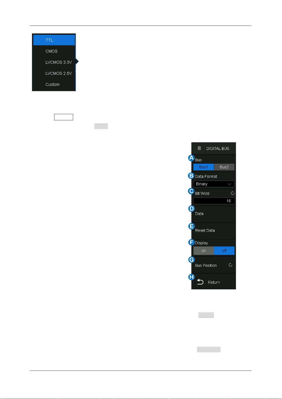
SDS1000X HD Series User Manual
54 i n t . s i g l e n t . c o m
The configurable logical level includes TTL, CMOS, LVCMOS 3.3 V,
LVCMOS 2.5 V, and Custom.
The setting range of the custom threshold is -8.0 V to + 8.0 V.
Bus Setting
Press the Digital button on the front panel or touch the Digital descriptor box on the bottom to open
the Digital dialog box, touch Bus to open the Digital Bus dialog box.
A. Select Bus1 or Bus2
B. Set the data format of the digital bus (binary, decimal,
unsigned decimal, and hexadecimal)
C. Set the bit width of the digital bus
D. Set the digital bus data
E. Reset the digital bus data to the default state
F. Enable/disable the display of the digital bus
G. Set the vertical position of the bus
H. Return to the previous menu
Bus Data Setting
The bus data setting supports setting the digital channel data by bit. Touch Data to open the bus
data setting dialog.
In this dialog, the mapping relationship between the bus bits and the digital channels is shown as
Bit.x[Dy]. For example, Bit.0[D15] means that bit 0 of the bus is D15. Touch Bit.x[Dy] to assign the
digital channel D0-D15 to the specified bit x.
Page 65
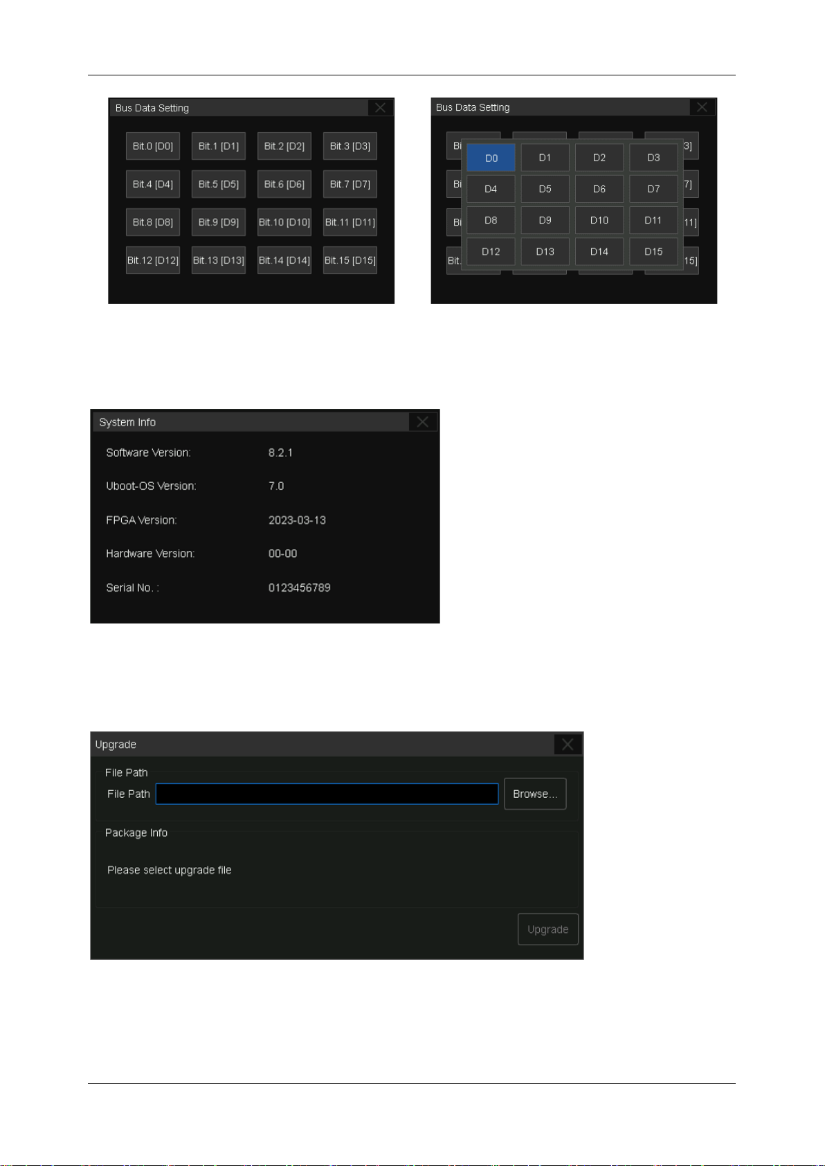
SDS1000X HD Series User Manual
int si glent.com 55
12.4 System
System Info – Includes Software Version,Uboot-OS Version, FPGA Version,Serial Number and
Hardware Version of the SLA1016 probe.
Page 66
SDS1000X HD Series User Manual
56 i n t . s i g l e n t . c o m
Upgrade
The firmware here refers to the firmware of the SLA1016 probe. The SDS1000X HD supports firmware
and configuration file upgrades for the SLA1016 via a U disk. Follow the steps below:
1. Copy the upgrade file (*.ADS) to the U disk.
2. Insert the U disk to one of the USB host ports of the oscilloscope.
3. Touch Browse… to select the path of the upgrade file. See the chapter "Save/Recall" for the
detailed operation.
4. Touch Upgrade to start the upgrade progress. A progress bar shows the percentage finished.
5. After the upgrade, the SLA1016 will be removed from the system, and the oscilloscope prompts
"Upgrade completed. Please reconnect the Digital device."
6. Enter the System Info dialog box again to check if the upgraded hardware version number is
consistent with the target version.
Warning: Don't cut off the power during the upgrade!
Page 67
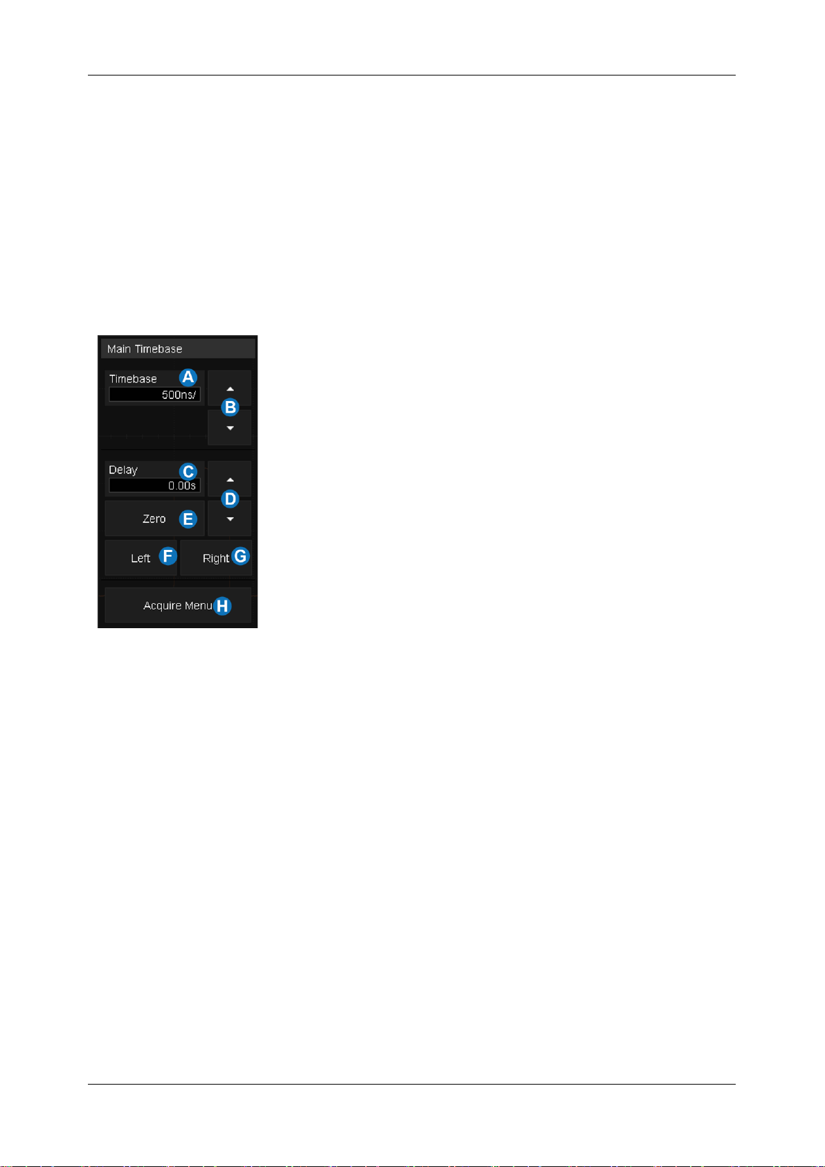
SDS1000X HD Series User Manual
int si glent.com 57
13 Horizontal and Acquisition Setup
13.1 Timebase Setup
The timebase setup is used to adjust the scale and offset of the X (horizontal) axis. This setting applies
to all analog, digital channels, and all math traces except FFT.
Touch the timebase descriptor box and the quick menu of the timebase settings will pop up. In the
menu timebase (horizontal scale), delay and other parameters can be set.
A. Set the horizontal scale (timebase) by the virtual keypad
B. ▲ to increase and ▼ to decrease the horizontal scale
C. Set the trigger delay by the virtual keypad
D. ▲ to increase and ▼ to decrease the trigger delay
E. Set the trigger delay to zero
F. Set the trigger delay to the left part of the screen
G. Set the trigger delay to the right part of the screen
H. Open the Acquire dialog box
Page 68
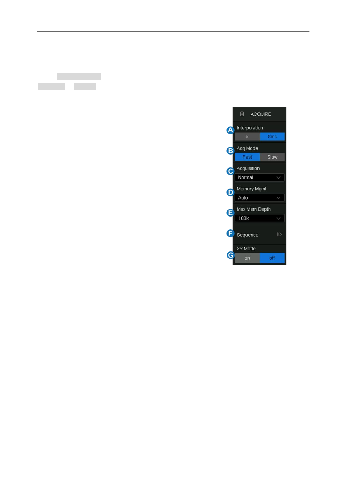
SDS1000X HD Series User Manual
58 i n t . s i g l e n t . c o m
13.2 Acquisition Setup
13.2.1 Overview
Touch Acquire Menu on the quick menu of the timebase settings, or touch the menu bar
Acquire > Menu to recall the Acquire dialog box on the right side.
A. Select the interpolation mode.
B. Select the Acq mode.
C. Select the acquisition mode (Normal & Peak Detect).
See the section "Acquisition" for details.
D. Select the Memory Management mode (Auto & Fixed
Sample Rate). See the section "Memory Management"
for details.
E. Select the maximum memory depth.
F. Enter the sequence menu. See the section “Sequence”
for details.
G. XY mode on/off.
Interpolation -- At small timebase settings, the number of original points on the screen may be less
than the number of display pixels in the grid area, so interpolation is necessary to display a continuous
waveform. For example, at 1 ns/div timebase and 2 GSa/s sample rate, the number of original points
is 20, but the grid area includes 1000 horizontal pixels. In this case, the oscilloscope needs to
interpolate the original points by 50.
X:
Linear interpolation, the simplest way of interpolation, connects two original points with a
straight line.
Sinc
: Sin(x)/x interpolation, the original point is interpolated according to the Nyquist
reconstruction formula, which has a good time-domain recovery effect for a sine wave. But for
step signals/fast rise times, it will introduce false overshoot due to the Gibbs phenomenon.
Page 69
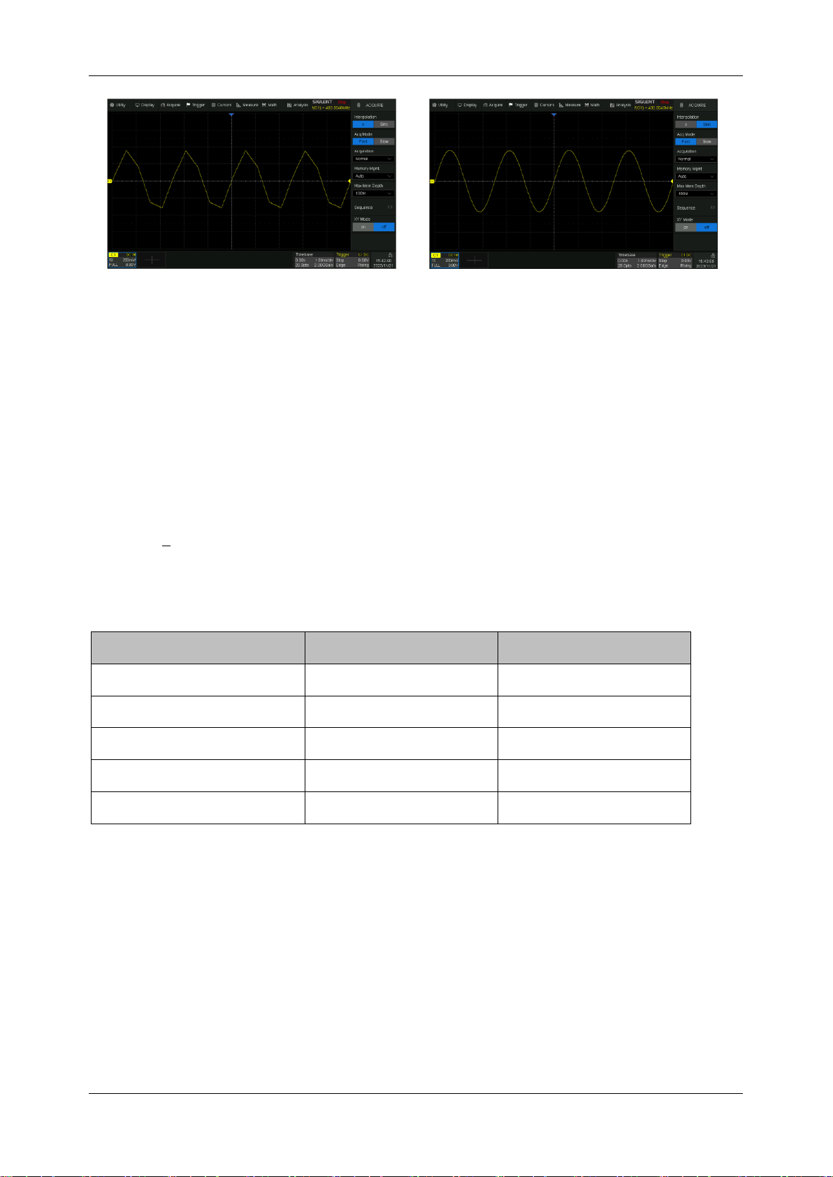
SDS1000X HD Series User Manual
int si glent.com 59
X Interpolation
Sinc Interpolation
Acq Mode: “Fast” is the default setting. The SDS1000X HD provides a very high waveform update
rate in fast mode. "Slow" mode will slow down the waveform update on purpose.
Memory Depth: The memory depth that can be supported. According to the formula "acquisition time
= sample points x sample interval", setting a larger memory depth can achieve a higher sample rate
for a given time base, but more samples require more processing time, degrading the waveform
update rate. SDS1000X HD can obtain the best waveform refresh rate with the Memory Depth of 1
kpts. Under the full Memory Depth, SDS1000X HD can still operate at full speed sampling at
timebases < 5 ms/div which provides high resolution captures for long time duration events.
The memory depth supported by the SDS1000X HD is listed in the following table:
Single Channel Mode
Dual-Channel Mode
Multi-Channel Mode
10 k
10 k
10 k
100 k
100 k
100 k
1 M
1 M
1 M
10 M
10 M
10 M
100 M
50 M
25 M
Single-channel mode: Only one of C1/C2/C3/C4 is turned on.
Dual-channel mode: Enable any 2 channels(e.g:C1&C3 or C1&C4).
Multi-channel mode: More than 2 channels have been opened(e.g:C1&C2&C3 or C1&C2&C3&C4).
XY Mode: A frame of data input by C1 is used as the x-axis, and a frame of data input by C2 is used
as the y-axis to display the relationship between the two signals. XY mode is usually used to draw a
Lissajous diagram or volt-ampere diagram of components.
Page 70
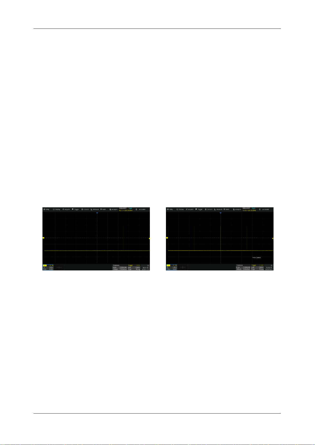
SDS1000X HD Series User Manual
60 i n t . s i g l e n t . c o m
13.2.2 Acquisition
The acquisition mode is used to determine how to acquire and process the signal.
Normal: The oscilloscope samples the signal with equal time intervals. For most waveforms, the best
display effect can be obtained using this mode.
Peak Detact:
Peak detect mode. The oscilloscope acquires the maximum and minimum values of
the signal within the sample interval so the peak (maximum-minimum) in the interval is obtained. This
mode is effective to observe occasional narrow pulses or spurs with a low sample rate, but the noise
displayed is larger. In peak mode, the oscilloscope will display all pulses with a pulse width longer
than 2ns.
In the following example, a narrow pulse sequence with a pulse width of 6.8 ns and a frequence of
200 Hz is sampled at a 5 MSa/s sample rate in normal mode and peak mode. As we can see, because
the sample interval (200 ns) is much larger than the pulse width (6.8 ns), it is difficult to capture the
narrow pulses in normal mode, but peak mode can ensure that each pulse is captured.
Normal mode
Peak mode
13.2.3 Memory Management
Memory Management controls how the instrument stores the acquired samples.
Auto: The default acquisition setting. After setting the maximum memory in the Auto mode, the
oscilloscope automatically adjusts the sample rate and memory depth according to the time base.
The adjustment principle is to follow the formula:
Sample rate = number of samples/time of acquisition
Where the time of acquisition is the time corresponding to the full display (i.e. 10 horizontal divisions).
Page 71
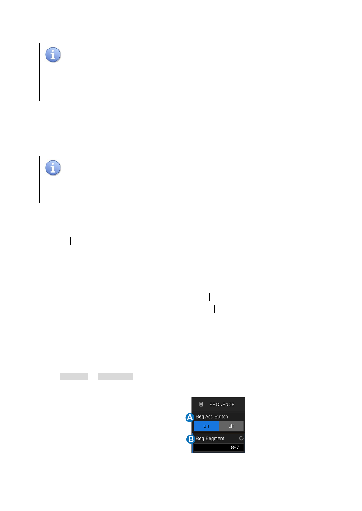
SDS1000X HD Series User Manual
int si glent.com 61
Note: The maximum memory here is the upper limit of the memory space allocated by
the oscilloscope. The actual sample points are related to the current time base and may
be less than memory depth. The actual sample points information can be obtained in
the timebase descriptor box (see the section "Timebase and Trigger Descriptor Boxes"
for details).
Fixed Sample Rate: The sample rate is fixed as set, and the oscilloscope automatically adjusts
memory depth according to the time base. The time of acquisition is the time corresponding to the full
display (i.e. 10 horizontal divisions).
Note: At Fixed Sample Rate, it is necessary to pay attention to whether the set sample
rate meets the Nyquist sample theorem with respect to the highest frequency of the
input signal. If the set sample rate is less than twice the maximum frequency of the input
signal, distorted signals will be obtained due to sampling aliasing.
13.2.4 Roll Mode
Press the Roll button on the front panel to enter roll mode. In this mode, the waveform moves
across the screen from right to left, similar to a strip chart recorder. The horizontal delay control of the
waveform will be disabled when roll mode is active. It only operates at timebase values of 50 ms/div
and above.
If you would like to stop the display in Roll mode, press the Run/Stop button. To clear the display
and restart an acquisition in Roll mode, press the Run/Stop button again.
Note: Zoom is only supported after Stop in Roll mode.
13.2.5 Sequence
Touch Acquire > Sequence to recall sequence dialog box.
A. Turn on or off sequence
B. Set the segment
Page 72
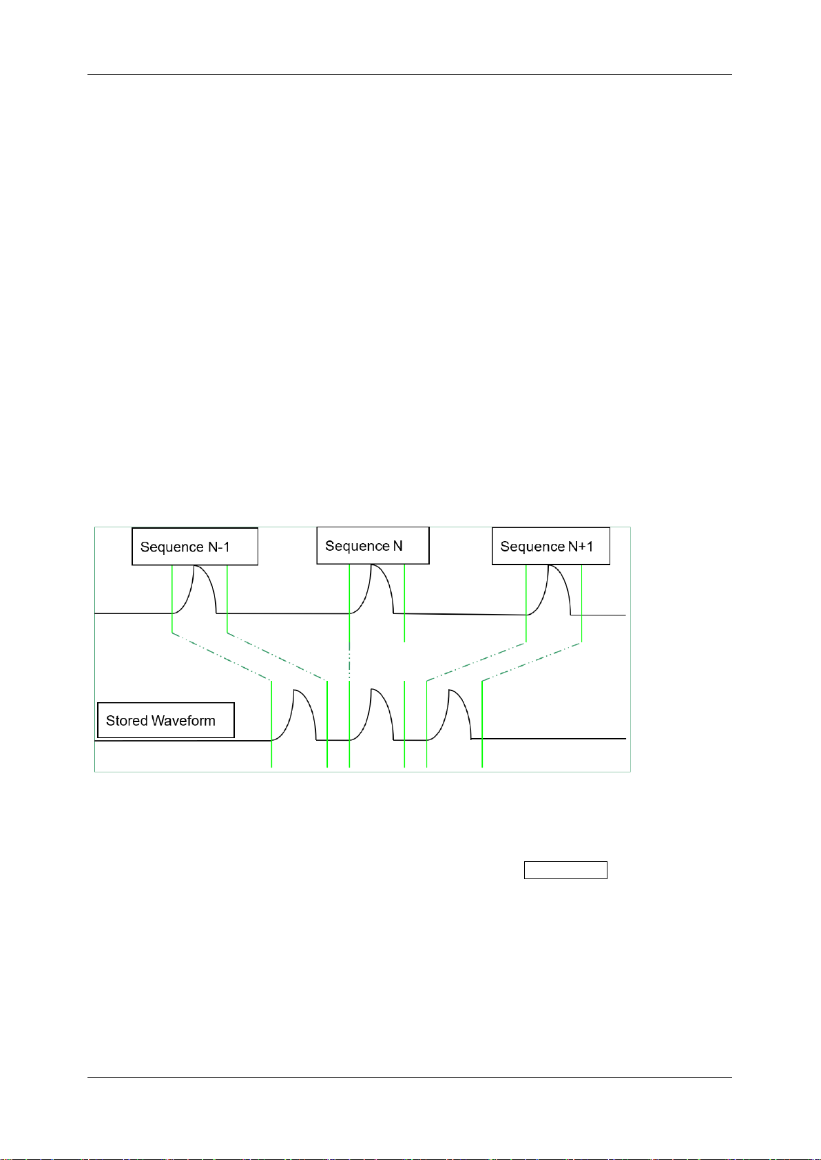
SDS1000X HD Series User Manual
62 i n t . s i g l e n t . c o m
Sequence mode is a fast acquisition mode, which divides the memory depth into multiple segments
(up to 80,000), each of which stores a single shot. In sequence mode, the oscilloscope only acquires
and stores data without processing and displaying, until the specified segments are acquired. As a
result, the dead time between trigger events is minimized, thus greatly improving the waveform update
rate. If sequence mode is enabled, the display will not update until all of the sequences have been
acquired. The SDS1000X HD can achieve a minimum 2 us trigger interval in Sequence mode,
corresponding to a waveform update rate of 500,000 wfm/s.
After the acquisition is finished, the oscilloscope will map all the segments together to the screen. If
you need to view and analyze each frame separately, history mode will help (see the section "
History" for details). History mode provides timestamp labels for each segment.
In addition to minimizing the dead time, another advantage of Sequence mode is that it can capture
and record rare events over long periods. The oscilloscope can capture multiple events that satisfy
the trigger conditions, ignoring the periods of no interest between adjacent events, thus maximizing
the use of waveform memory. You can use the full accuracy of the acquisition timebase to measure
selected segments.
Example:
Input a pulse sequence with a period of 20 ms to C1. The rise time of the pulse is 2 ns, while fall time
is 200 ns; pulse width is 200 ns, and amplitude is 3.2 Vpp. Press the AutoSetup button on the front
panel.
Set the coupling mode of C1 to DC50Ω, and vertical scale to 500 mV/div, vertical offset to 0. Set the
trigger level to 0.
Page 73
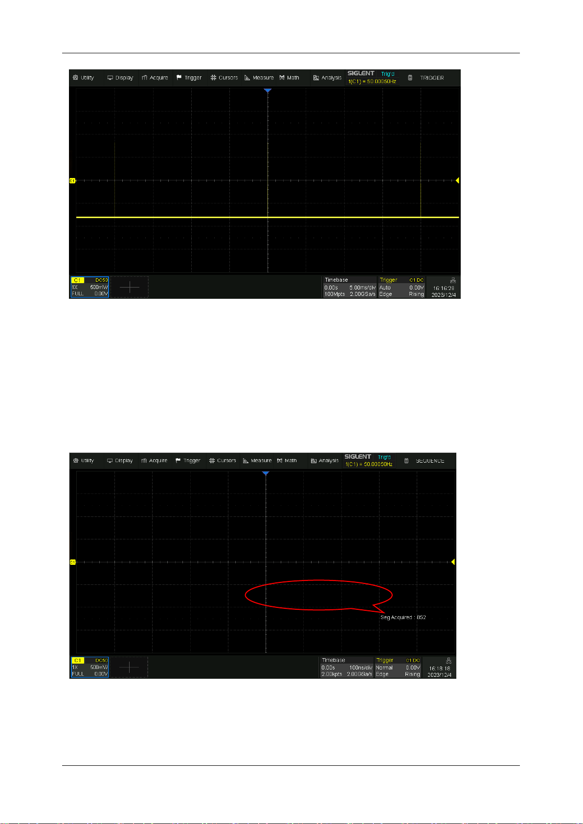
SDS1000X HD Series User Manual
int si glent.com 63
In normal mode, 3 pulses can be obtained on the screen with the sample rate of 2GSa/s
at the maximum memory depth.
Set the trigger mode to "Single", the timebase to 100 ns/div. Turn on the Sequence mode, and set
the segments to maximum (45976 in this example, up to 80,000 depending on the number of samples
at the current time base). Wait patiently until the acquisition completes, then all the waveforms
satisfying the trigger conditions are displayed on the screen.
In Sequence mode, there is no waveform displayed on the screen until the acquisition is
completed. During acquisition, there is a counter on the screen indicating the number of
segments that have been acquired.
Seg Acquired: 852
Page 74
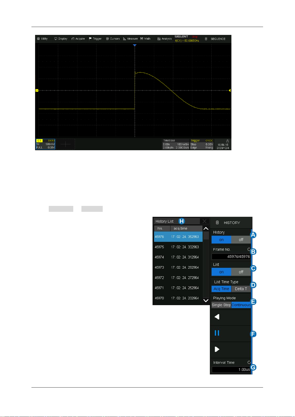
SDS1000X HD Series User Manual
64 i n t . s i g l e n t . c o m
In the example, 45976 pulses can be obtained with the sample rate of 2 GSa/s at the
maximum memory depth.
13.3 History
Touch Analysis > History to recall the history dialog box.
A. Turn on or off history mode
B. Specify the frame index
C. Turn on or off the list
D. List time type
E. Set the playing mode
F. Play backward, pause, and play forward
G. Set the time interval between two frames
when playing automatically
H. List displays the frame index and time
label for each frame
Page 75
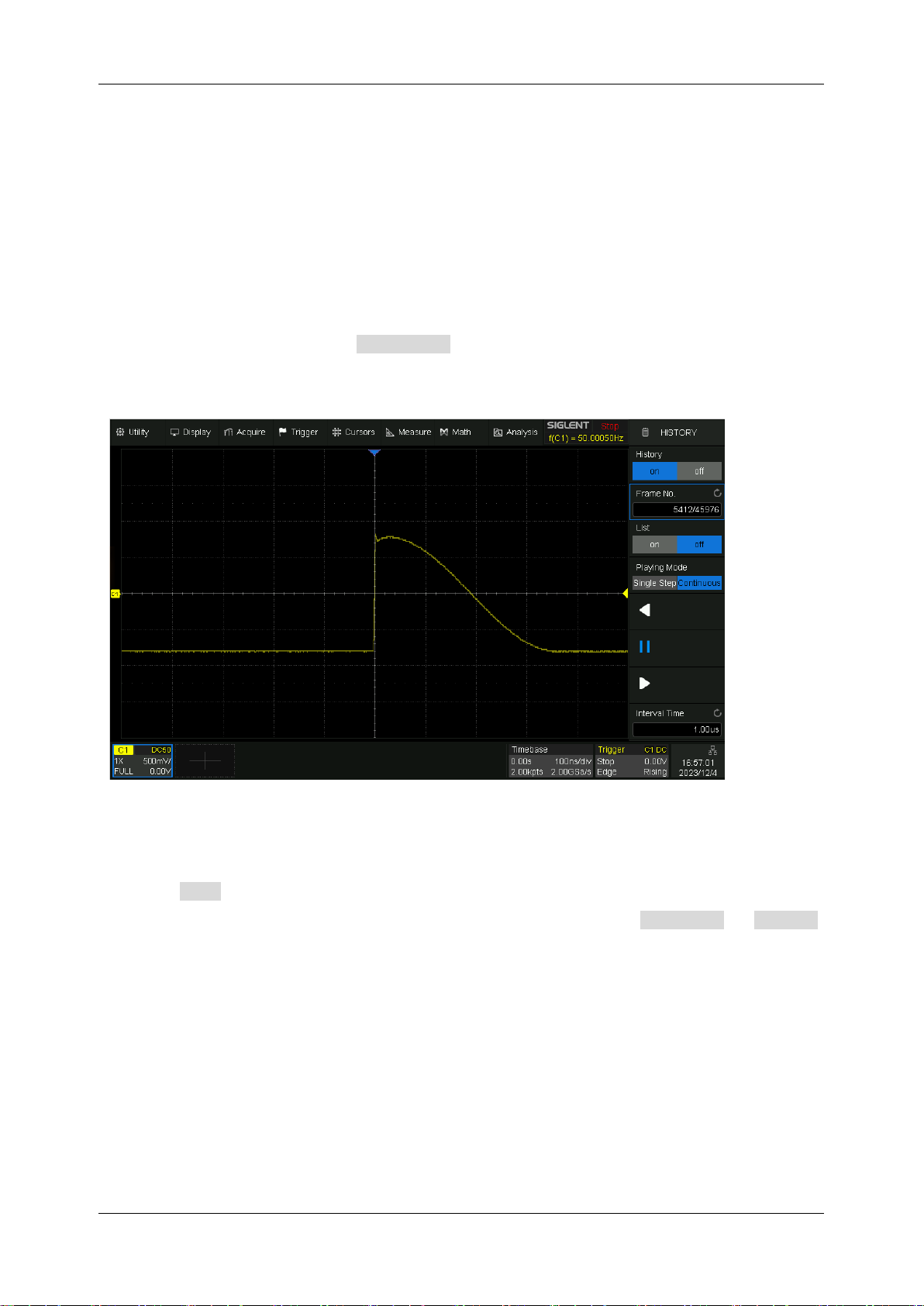
SDS1000X HD Series User Manual
int si glent.com 65
The oscilloscope automatically stores acquired frames. It can store up to 80,000 frames but the
number may vary due to the memory depth and timebase settings. Turn on history mode, then the
stored frames can be recalled and measured.
Continue with the example in the section above. In Sequence mode, all waveforms that satisfy the
trigger conditions are mapped to the display. If you need to observe a single frame, you can use
history mode.
To enable history mode, touch the Frame No. . area twice, then the virtual numeric keypad pops
up. Input the number "5412" to specify the 5412th segment (frame).
Observing the 5412th frame captured by Sequence in history mode
Touch the List area, turn on the list, in which the time label corresponding to the 5412th waveform
is displayed. The time resolution is microseconds. Time label types include Acq Time or Delta T ,
AcqTime corresponds to the absolute time of the frame, synchronized with the real-time clock of the
oscilloscope; Delta T is the acquisition time interval between adjacent two frames, it is shown as 20ms
in the following diagram, which is consistent with the period of the actual waveform.
Page 76
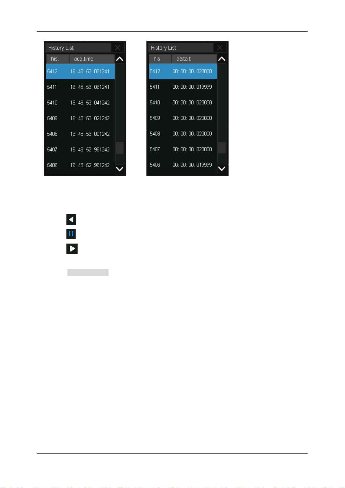
SDS1000X HD Series User Manual
66 i n t . s i g l e n t . c o m
Acq Time label
Delta T label
In addition to manually specifying a frame, history mode supports autoplay:
Press the softkey to replay the waveform from the current frame to the first.
Press the softkey to stop replay.
Press the softkey to replay the waveform from the current frame to the last.
Touch the Interval Time area to control the speed of automatic play. In the process of automatic
play, the list will automatically scroll to the current frame.
Note: When a measurement is enabled in history mode, if the Interval Time is set to small (e.g. in us)
the speed of automatic play may not meet the setting, because measurements may take a longer
time for each frame.
Page 77
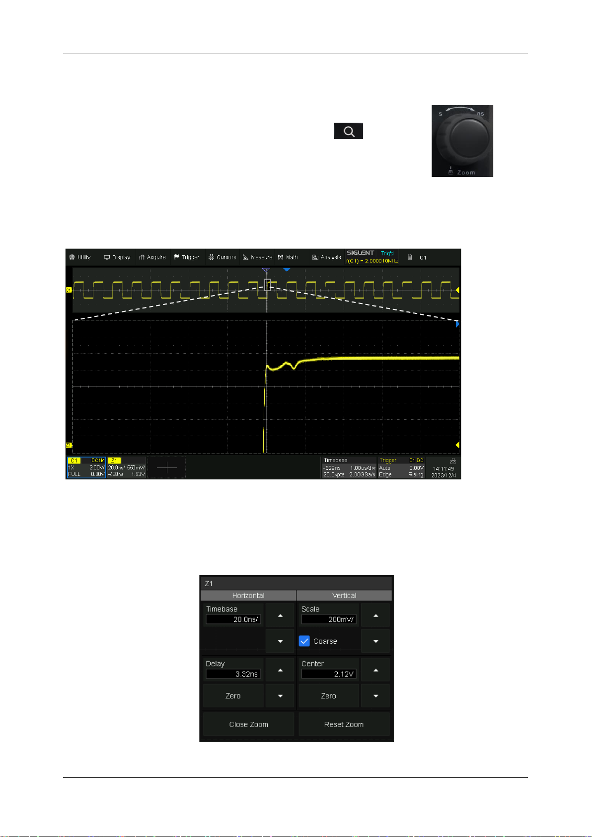
SDS1000X HD Series User Manual
int si glent.com 67
14 Zoom
The SDS1000X HD supports waveform zoom in the horizontal and
vertical directions. Press down the horizontal knob or the button
on the front panel to turn on the zoom function.
When the Zoom function is on, the waveform area is divided into upper and lower parts. The area of
about 1/3 height above is the main window, and the area of about 2/3 height below is the zoom window.
Touch a window to activate it. The currently activated window is highlighted by the dashed line.
The area not covered by the gray background in the main waveform area is the range to be zoomed
in (zoom area). Touch the Zoom Vertical Parameters and Zoom Horizontal Parameters regions shown
in the figure above to recall the quick dialogs for setting the vertical and horizontal parameters of the
zoom window.
Zoom setting
Main
Zoom Window
Zoom Descriptor Box
Page 78
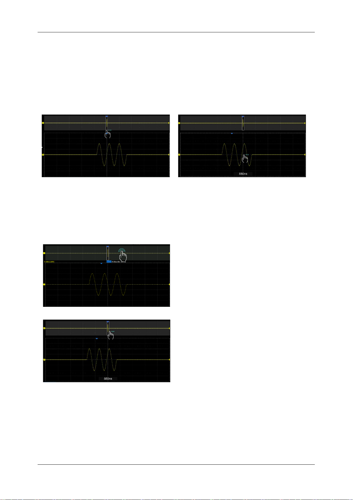
SDS1000X HD Series User Manual
68 i n t . s i g l e n t . c o m
When the zoom window is activated, the zoom area can be expanded or compressed by rotating the
horizontal and vertical scale knob. Rotating the horizontal and vertical position knob to move the
position of the region. When the main window is activated, the scale knobs and position knobs are
used to change the scale and delay/offset of the main window. The operations above can also be
performed by different gestures. Below is the example of changing the setting in the horizontal
direction by gestures. The gestures for changing the setting in the vertical direction are similar.
Adjust the horizontal position of the zoom area by dragging left and right in the zoom area of the
main window or waveform in the Zoom window
Adjust the vertical position of the zoom area by dragging up and down in the zoom area of the
main window or waveform in the Zoom window.
Double click a location in the main window to
quickly set the center of the zoom area.
Adjust the horizontal position of the waveform
by dragging left and right in the gray area of the
main window
Adjust the vertical position of the waveform by
dragging up and down in the gray area of the
main window.
Page 79
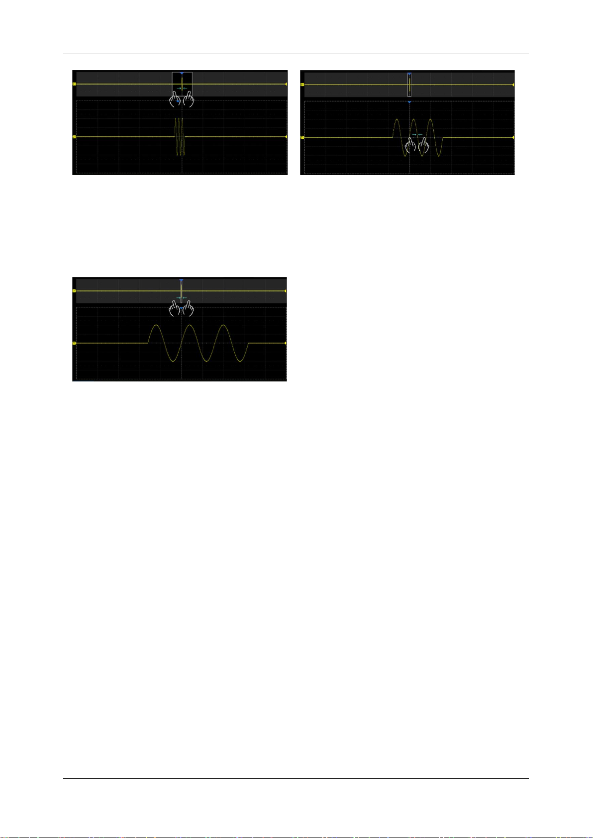
SDS1000X HD Series User Manual
int si glent.com 69
Adjust the horizontal scale of the Zoom window by horizontal pinch and spread in the zoom area
of the main window or the Zoom window
Adjust the vertical scale of the Zoom window by vertical pinch and spread in the zoom area of the
main window or the Zoom window.
Adjust the horizontal/ vertical scale of the main
window by using a pinching or spreading
gesture in the gray area of the main window
Note: Zoom traces (Z1~Z4) can be used as the source of Measurement, Math and Mask test.
Page 80
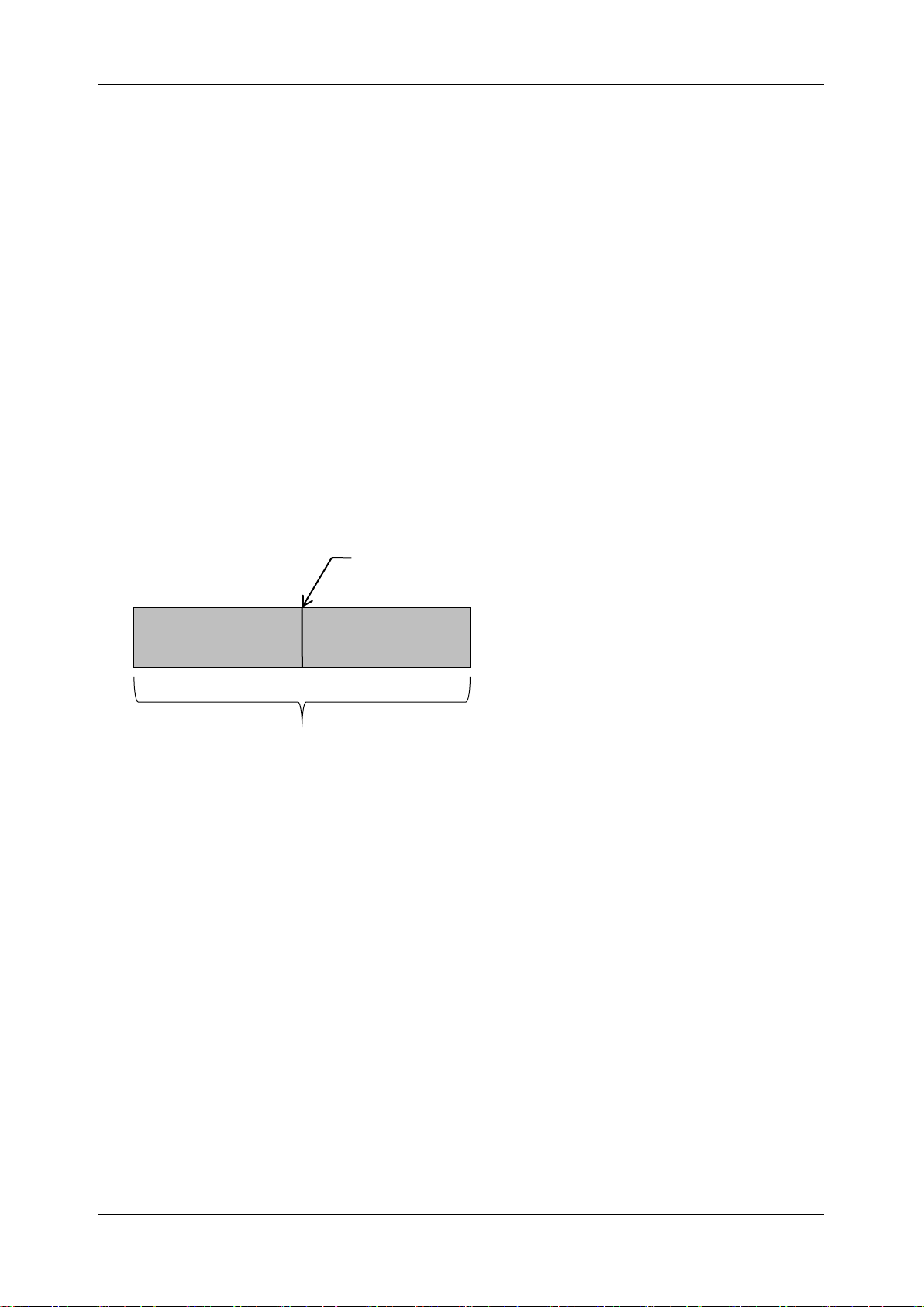
SDS1000X HD Series User Manual
70 i n t . s i g l e n t . c o m
15 Trigger
15.1 Overview
The oscilloscope only acquires waveforms of interest (i.e. the ones that satisfy the trigger condition)
and aligns all trigger events at the trigger position to form a stable waveform display. The trigger is
one of the most important features of an oscilloscope since we can only analyze a signal that we can
trigger reliably and stably.
The trigger position is movable on the display. The following diagram shows the structure of the
acquisition memory. The acquisition memory is divided into pre-trigger and post-trigger buffers and
the boundary between them is the trigger position. Before the trigger event arrives, the oscilloscope
fills the pre-trigger buffer first, and then continuously updates it in FIFO mode until the trigger event
arrives. After the trigger event, the data fills the post-trigger buffer. When the post-trigger buffer is full,
an acquisition is completed.
Below is the definition of the states in the process of filling the acquisition memory:
Arm: The pre-trigger buffer is not full, and the oscilloscope does not respond to any trigger events.
Ready: The pre-trigger buffer is full, and the oscilloscope is waiting for the trigger event.
Trig’d: A trigger event is detected and the oscilloscope starts to fill the post-trigger buffer.
Trigger settings should be based on the features of the input signal. For example, a sine wave with a
repeatable period can be triggered on the rising edge; for capturing hazards in a combinational logic
circuit, the pulse trigger can be set. You need to have some knowledge of the signal-under-test to
quickly capture the desired waveform.
Pre-trigger Buffer
Post-trigger Buffer
Trigger Event
Acquisition Memory
Page 81
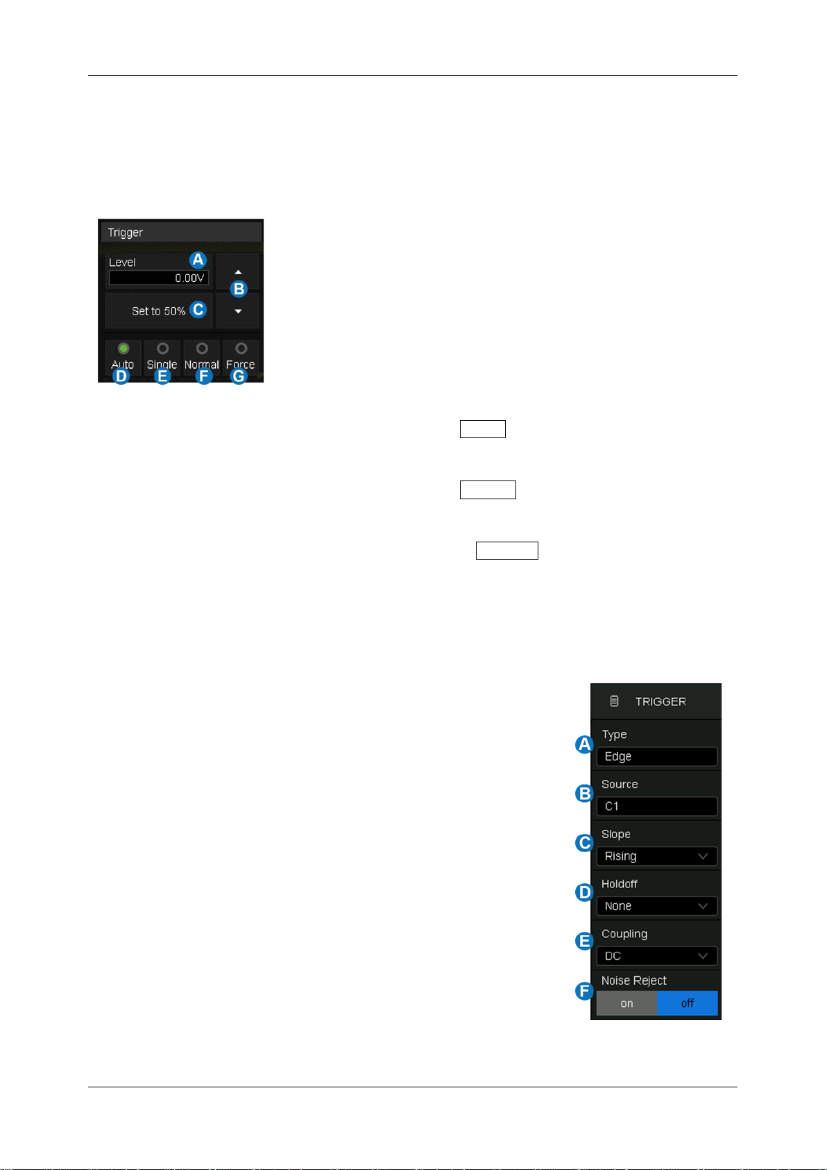
SDS1000X HD Series User Manual
int si glent.com 71
15.2 Trigger Setup
Touch the trigger descriptor box to display the quick menu of trigger settings. The trigger setup dialog
box is displayed on the right side of the screen.
Quick menu
A. Touch the level region and rotate the
Level
knob on
the front panel to adjust the trigger level; touch the
region again and the virtual keypad will be available
B. ▲ to increase and ▼ to decrease the trigger level
C. Set trigger level to the vertical center of the waveform
automatically
D. Set the trigger mode to "Auto", which is equivalent to
pressing the Auto button on the front panel
E. Set the trigger mode to "Single", which is equivalent to
pressing the Single button on the front panel
F. Set the trigger mode to "Normal", which is equivalent
to pressing the Normal button on the front panel
G. Set the trigger mode to "Force", No key control, see the
chapter "Trigger Mode" for details
Trigger setup dialog box:
A. Select trigger type
B. Select the trigger source
C. Select the trigger slope (When the trigger type is “Edge”,
“Slope” and other specific types)
D. Set holdoff (None & Time)
E. Set trigger coupling mode (DC/AC/LF Reject/HF Reject)
F. Enable/disable Noise Rejection. When Noise Reject is
on, the trigger hysteresis is increased, so the noise
immunity of the trigger circuit is better. As a compromise,
the trigger sensitivity degrades
Page 82
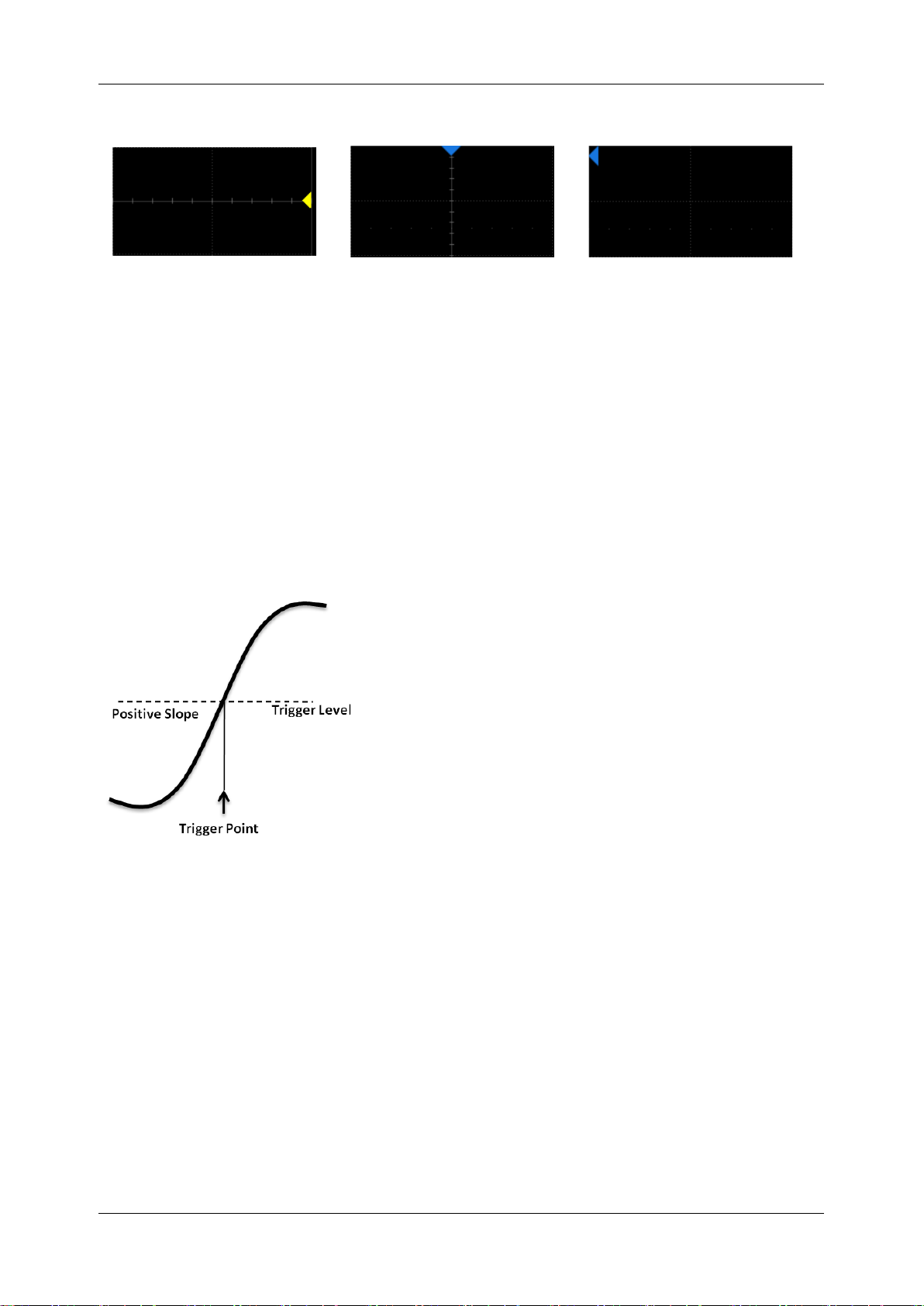
SDS1000X HD Series User Manual
72 i n t . s i g l e n t . c o m
Trigger Related Label
Trigger level Indicator
Horizontal 0 position Indicator
Horizontal 0 position
(out of screen) Indicator
15.3 Trigger Level
Both analog and digital triggers must have a correct trigger level value. The oscilloscope judges
whether a waveform satisfies the trigger condition when it crosses the trigger level. If it does, the
crossing time is the trigger position. In the following figure, the trigger condition is set as a rising edge.
When the signal with a positive slope crosses the trigger level, the trigger condition is satisfied and
the time point the signal crosses the level is the trigger position.
In some special triggers, the system will automatically set the trigger level, such as using AC Line as
the trigger source.
15.4 Trigger Mode
The trigger mode determines how the oscilloscope acquires waveforms.
Auto: An internal timer triggers the sweep after a preset timeout period if no trigger has been found
so that the oscilloscope continuously updates the display whether a trigger happens or not. Auto mode
is suitable for unknown signals or DC signals.
Page 83

SDS1000X HD Series User Manual
int si glent.com 73
Note: In Auto mode, if the signal satisfies the trigger conditions but cannot trigger the oscilloscope
stably, it may be that interval between two trigger events exceeds the timeout period. Try Normal
mode in this case.
Normal: Triggers and acquisitions only occur when the trigger conditions are met. Otherwise, the
oscilloscope holds the last waveform on the display and waits for the next trigger. Normal mode is
suitable for acquiring:
Only events specified by the trigger settings
Rare events
Single: Captures and displays a single frame that satisfies the trigger conditions, and then stops. The
following trigger events are ignored until the Single acquisition is restarted. Single-mode is suitable
for:
One-shot events or periodic signals, such as power-on\off waveforms on a power rail
Rare events
Force: Forces a frame to be triggered regardless of whether the input signal meets the trigger
conditions. Under different trigger modes, the manifestations are different:
Auto: After a forced trigger for one frame, return to Auto trigger, forcing only one frame
refresh effect;
Normal: After a forced trigger for one frame, return to Normal trigger;
Single: After forcibly triggering a frame, return to Stop mode.
Since the front panel does not have forced trigger button, a shortcut for forced trigger is added to the
top trigger drop-down menu and the bottom trigger information pull-up menu.
Page 84
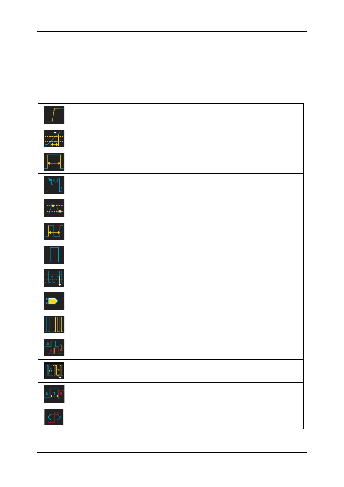
SDS1000X HD Series User Manual
74 i n t . s i g l e n t . c o m
15.5 Trigger Type
15.5.1 Overview
The trigger modes of the SDS1000X HD are digital designs. Compared with analog trigger circuits,
digital triggers can not only greatly optimize trigger precision and trigger jitter, but also support multiple
trigger types and complex trigger conditions.
Edge-- Trigger on a rising edge, falling edge or both
Slope-- Trigger when an edge crosses two thresholds that lie inside or outside a
selected time range
Pulse--Trigger at the end of a pulse when the pulse width lies inside or outside a
selected time range
Video--TV trigger on falling edge
Window--Trigger when the signal leaves the widow region.
Interval--Trigger on the second edge when the time between the edges is inside or
outside a selected time range
Dropout--Trigger when the signal disappears for longer than the Dropout value.
Runt--Trigger when a pulse crosses the 1st threshold but not the 2nd before re-
crossing the 1st threshold again
Pattern-- Trigger when pattern condition transitions from false to true. All inputs set to
DC coupling
Serial--Trigger on specified condition in a serial bus. See the chapter "Serial Trigger
and Decode" for details.
Qualified -- Trigger with edge trigger setting only after the qualifying condition is
satisfied
Nth Edge –Trigger on the Nth edge of a burst that occurs after a specified idle time
Delay --Trigger when the delay time between source A and source B meets the limit
condition
Setup/Hold --Trigger when the setup time or hold time meets the limit condition
Page 85
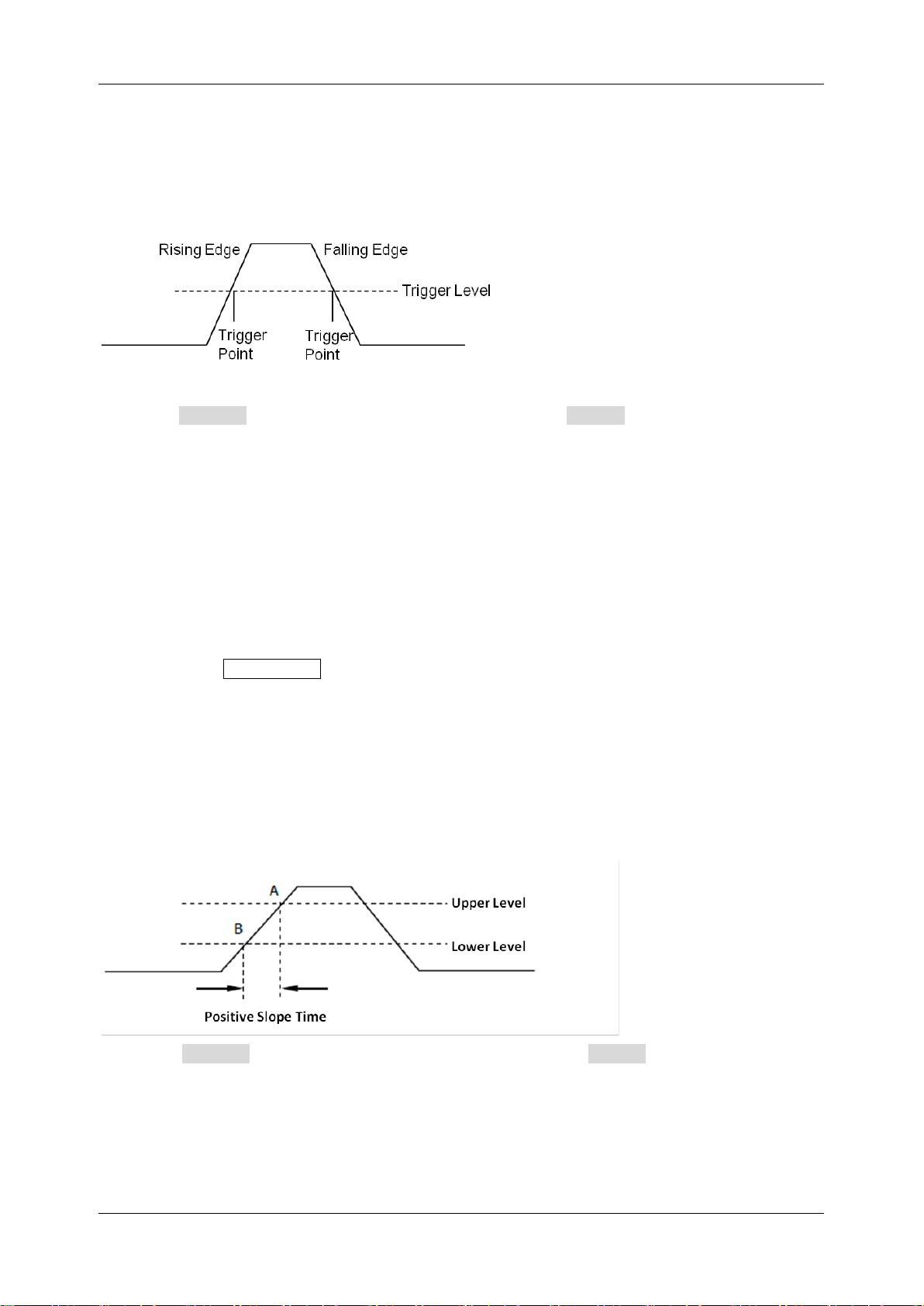
SDS1000X HD Series User Manual
int si glent.com 75
15.5.2 Edge Trigger
Edge trigger distinguishes the trigger points by seeking the specified edge (rising, falling, alternating)
and trigger level. The trigger source and slope can be set in the trigger dialog box.
Touch the Source area to select trigger source, and touch the Slope area to select rising, falling,
or alternating.
Rising -- Only trigger on the rising edge
Falling -- Only trigger on the falling edge
Alternating -- Trigger on both rising edge and falling edge
Holdoff, coupling, and noise reject can be set in edge trigger, see the sections "Holdoff", "Trigger
Coupling" and "Noise Reject" for details.
Note: Press the Auto Setup button, and the oscilloscope will set the trigger type to Edge.
15.5.3 Slope Trigger
The slope trigger looks for a rising or falling transition from one level to another level in the specified
time range. For example, positive slope time is defined as the time difference between the two
crossing points of trigger level lines A and B with the positive edge as shown in the figure below.
Touch the Source area to select trigger source, and touch the Slope area to select rising or
falling.
Rising -- Only trigger on the positive slope
Falling -- Only trigger on the negative slope
Page 86
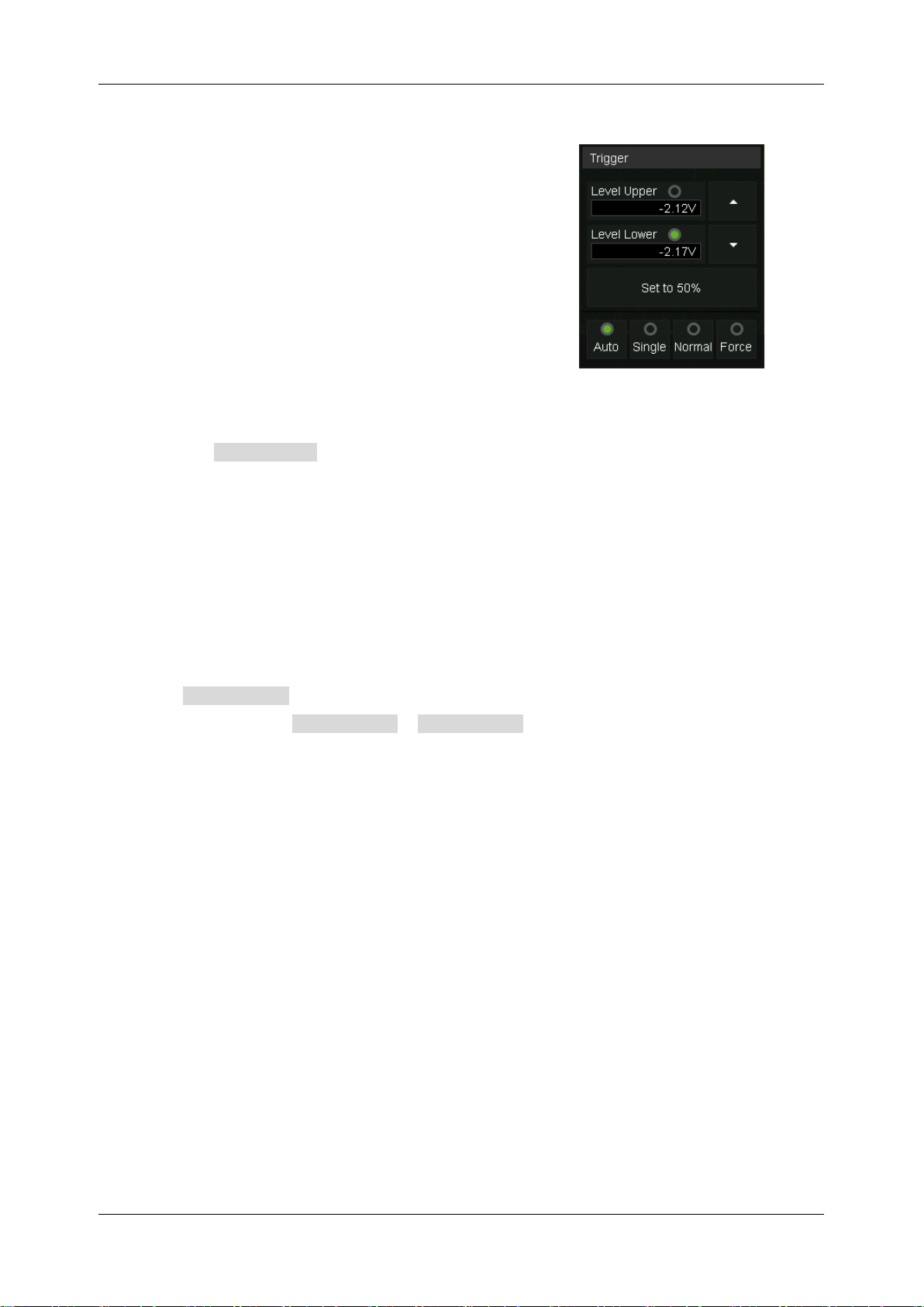
SDS1000X HD Series User Manual
76 i n t . s i g l e n t . c o m
Adjust Upper/Lower Level
The slope trigger requires upper and lower trigger levels.
When the trigger type is slope trigger, touch the trigger
descriptor box, and the pop-up quick menu will show two
levels.
The upper/lower level can be set in the following two ways:
1. Touch the Level Upper area in the quick menu to select the upper level, and then set the level
value by the virtual keypad or the Level knob on the front panel. To set the lower level is similar.
2. Use the Level knob on the front panel directly to set the level value. Press the knob to switch
between upper and lower levels, and rotate it to set the value.
The lower level should always be less than or equal to the upper level. In the trigger descriptor box,
the lower level is displayed.
Set Limit Range
Touch the Limit Range area in the trigger dialog box to select the time condition and set the
corresponding time in the Upper Value / Lower Value area.
Less than a time value (<=) -- Trigger when the positive or negative slope time of the input signal is
lower than the specified time value.
Great than a time value (>=) -- Trigger when the positive or negative slope time of the input signal
is greater than the specified time value.
Within a range of time values ([--,--]) -- Trigger when the positive or negative slope time of the input
signal is greater than the specified lower limit of time and lower than the specified upper limit of time
value.
Outside a range of time value (--][--) -- Trigger when the positive or negative slope time of the input
signal is greater than the specified upper limit of time and lower than the specified lower limit of time
value.
Holdoff, coupling, and noise reject can be set in slope trigger, see the sections "Holdoff", "Trigger
Coupling" and "Noise Reject" for details.
Page 87
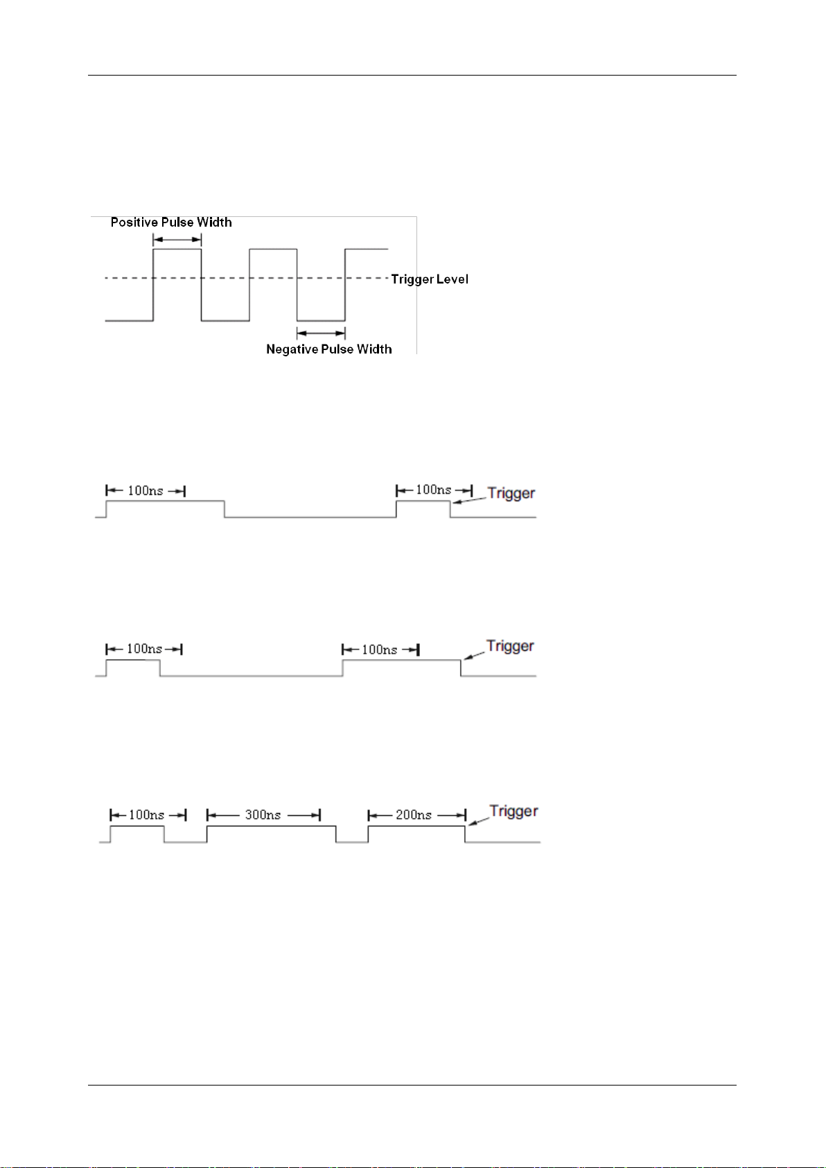
SDS1000X HD Series User Manual
int si glent.com 77
15.5.4 Pulse Trigger
Trigger on a positive or negative pulse with a specified width. Trigger source, polarity (positive,
negative), limit range, and time value can be set in the trigger dialog box.
Less than a time value (<=) -- Trigger when the positive or negative pulse time of the input signal is
lower than the specified time value. Below is an example of a trigger condition set to a positive pulse
width < 100ns
Great than a time value (>=) -- Trigger when the positive or negative pulse time of the input signal
is greater than the specified time value. Below is an example of a trigger condition set to a positive
pulse width > 100ns
Within a range of time values ([--,--]) -- Trigger when the positive or negative pulse time of the input
signal is greater than the specified lower limit of time and lower than the specified upper limit of the
time value. Below is an example of a trigger condition set to 100 ns < positive pulse width < 300 ns.
Outside a range of time value (--][--) -- trigger when the positive or negative pulse time of the input
signal is greater than the specified upper limit of time and lower than the specified lower limit of the
time value.
Holdoff, coupling, and noise reject can be set in pulse trigger, see the sections "Holdoff", ”Trigger
Coupling" and "Noise Reject" for details.
Page 88
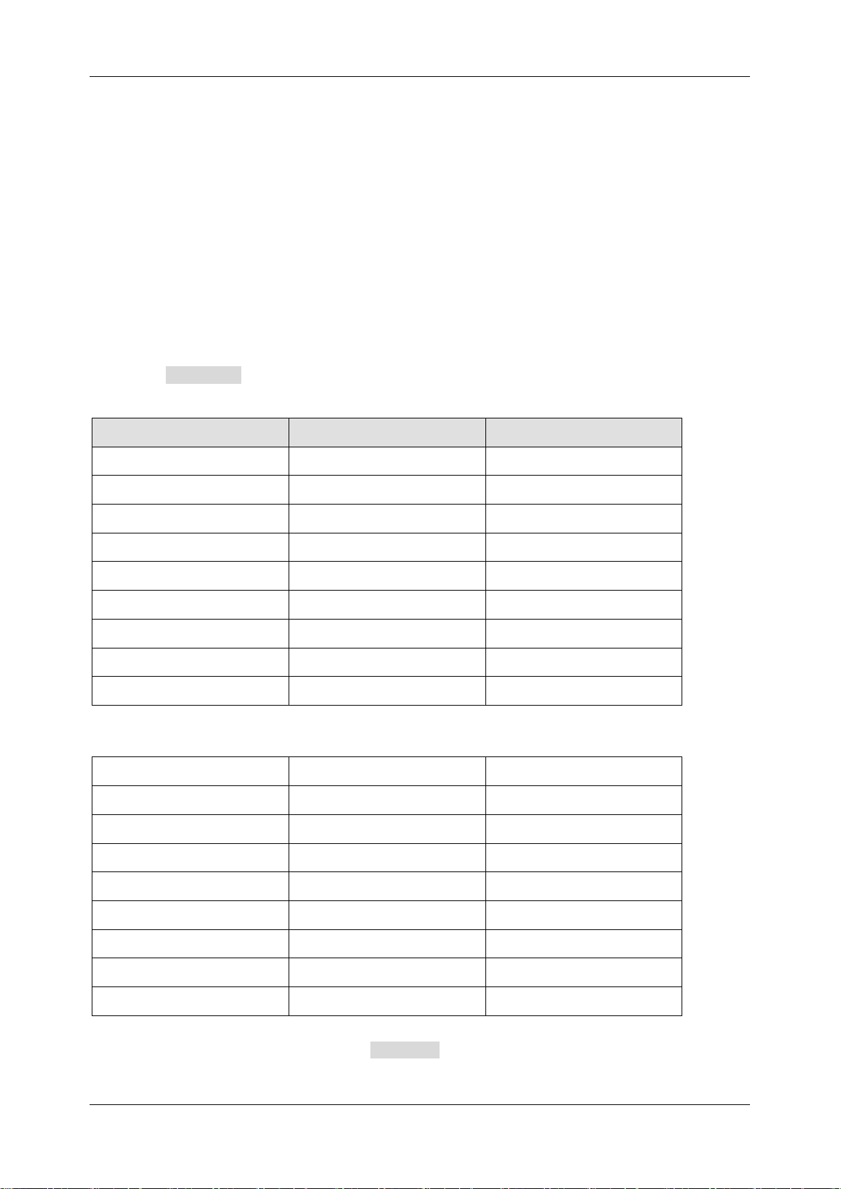
SDS1000X HD Series User Manual
78 i n t . s i g l e n t . c o m
15.5.5 Video Trigger
Video trigger can be used to capture the complicated waveforms of most standard analog video
signals. The trigger circuitry detects the vertical and horizontal interval of the waveform and produces
a trigger based on the video trigger settings you have selected. The SDS1000X HD supports standard
video signals for NTSC (National Television Standards Committee), PAL (Phase Alternating Line),
HDTV (High Definition Television), and a custom video signal trigger.
Source, standard, and synchronization mode can be set in the video trigger dialog box. When the
synchronization mode is "Select", line and field can be specified.
Touch the Standard and select the video standard. The SDS1000X HD supports the following
video standards:
TV Standard
Scan Type
Sync Pulse
NTSC
Interlaced
Bi-level
PAL
Interlaced
Bi-level
HDTV 720P/50
Progressive
Tri-level
HDTV 720P/60
Progressive
Tri-level
HDTV 1080P/50
Progressive
Tri-level
HDTV 1080P/60
Progressive
Tri-level
HDTV 1080i/50
Interlaced
Tri-level
HDTV 1080i/60
Interlaced
Tri-level
Custom
The table below shows the parameters of the custom video trigger:
Frame Rate
25Hz, 30 Hz, 50 Hz,60 Hz
Of Lines
300 ~ 2000
Of Fields
1,2,4,8
Interlace
1:1, 2:1,4:1,8:1
Trigger Position
Line
Field
(line value)/1(1:1)
1 (line value)/2 (2:1)
1,2, 3, 4,5,6,7,8
(line value)/4(4:1)
1,2, 3, 4,5,6,7,8
(line value)/8(8:1)
1,2, 3, 4,5,6,7,8
Line value: The number of lines set in the Of Lines (300 ~ 2000).
Page 89
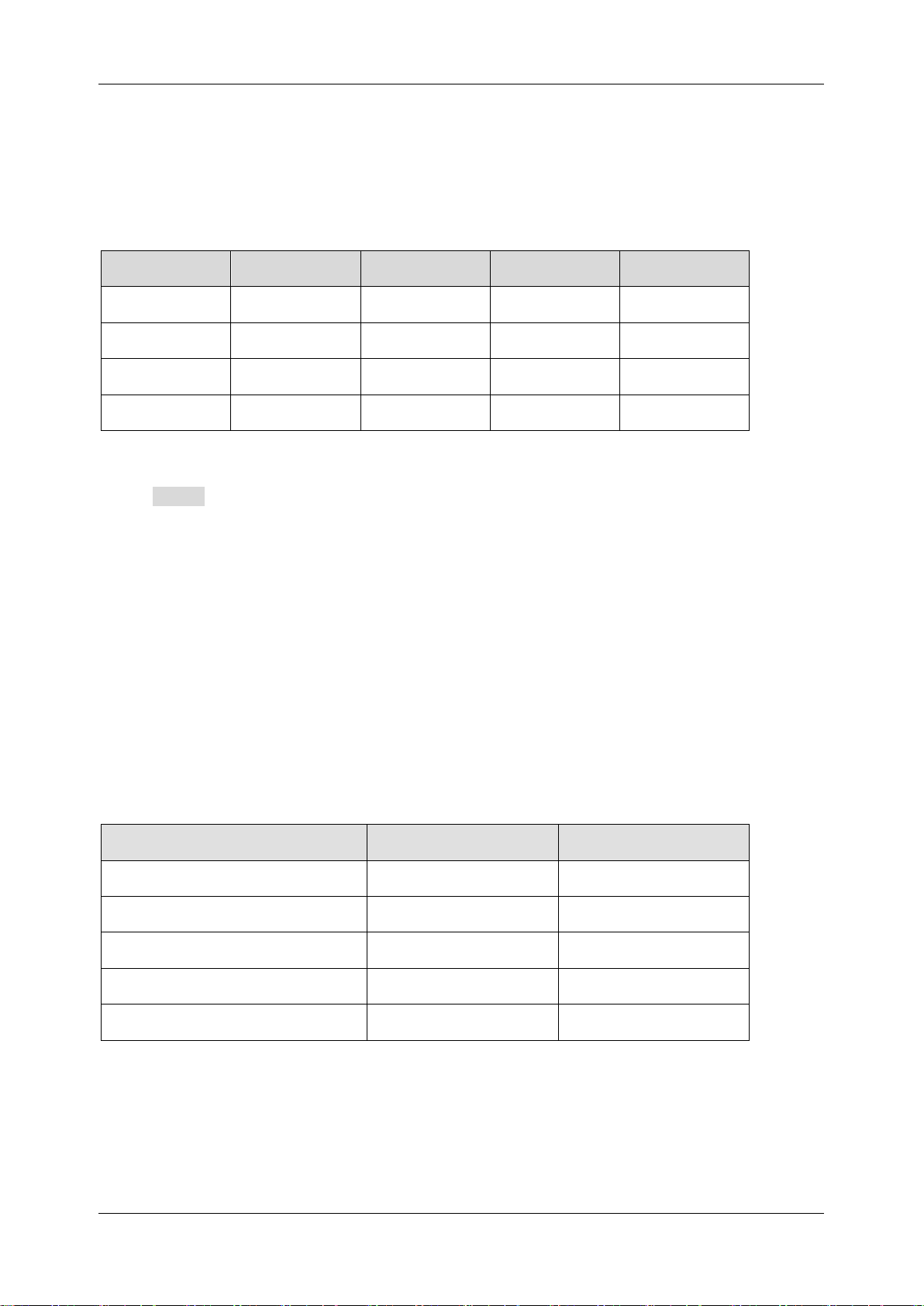
SDS1000X HD Series User Manual
int si glent.com 79
In the custom video trigger type, the corresponding "Of Fields" varies with the selection of the
“Interlace” ratio. Therefore, the number of fields selected and the number of lines corresponding to
each field can also be varied. If the "Of Lines" is set to 800, the correct relationship between them is
as follows:
Of Lines
Interlace
Of Fields
Trigger Line
Trigger Field
800
1:1 1 800
1
800
2:1
1/2/4/8
400
1/1~2/1~4/1~8
800
4:1
1/2/4/8
200
1/1~2/1~4/1~8
800
8:1
1/2/4/8
100
1/1~2/1~4/1~8
Set the video trigger for a video signal
Touch Sync for trigger mode selection, video trigger mode has "Any" and "Select" options. In "Any"
mode, the video signal can be triggered on any line that meets the conditions. In the "Select" mode,
the signal can be triggered by a specified field and a specified line.
For progressive scanning signals (e.g. 720p/50, 720p/60, 1080p/50, 1080p/60), only the specified line
can be selected to trigger when the synchronization mode is “Select”.
For interlaced scanning signals (such as NTSC, PAL, 1080i/50, 1080i/60, Custom), when the
synchronization mode is "Select", the specified line and the specified field can be selected to trigger.
The following table shows the corresponding relations between line and field for all video standards
(except for Custom)
Standard
Field 1
Field 2
NTSC
1 to 263
1 to 262
PAL
1 to 313
1 to 312
HDTV 720P/50 , 720P/60
1 to 750
HDTV 1080P/50 , 1080P/60
1 to 1125
HDTV 1080i/50 , 1080i/60
1 to 563
1 to 562
To gain familiarization with the video trigger, try these two examples:
Trigger on a specific line of video (NTSC standard)
Use “Custom” to trigger video signals
Page 90
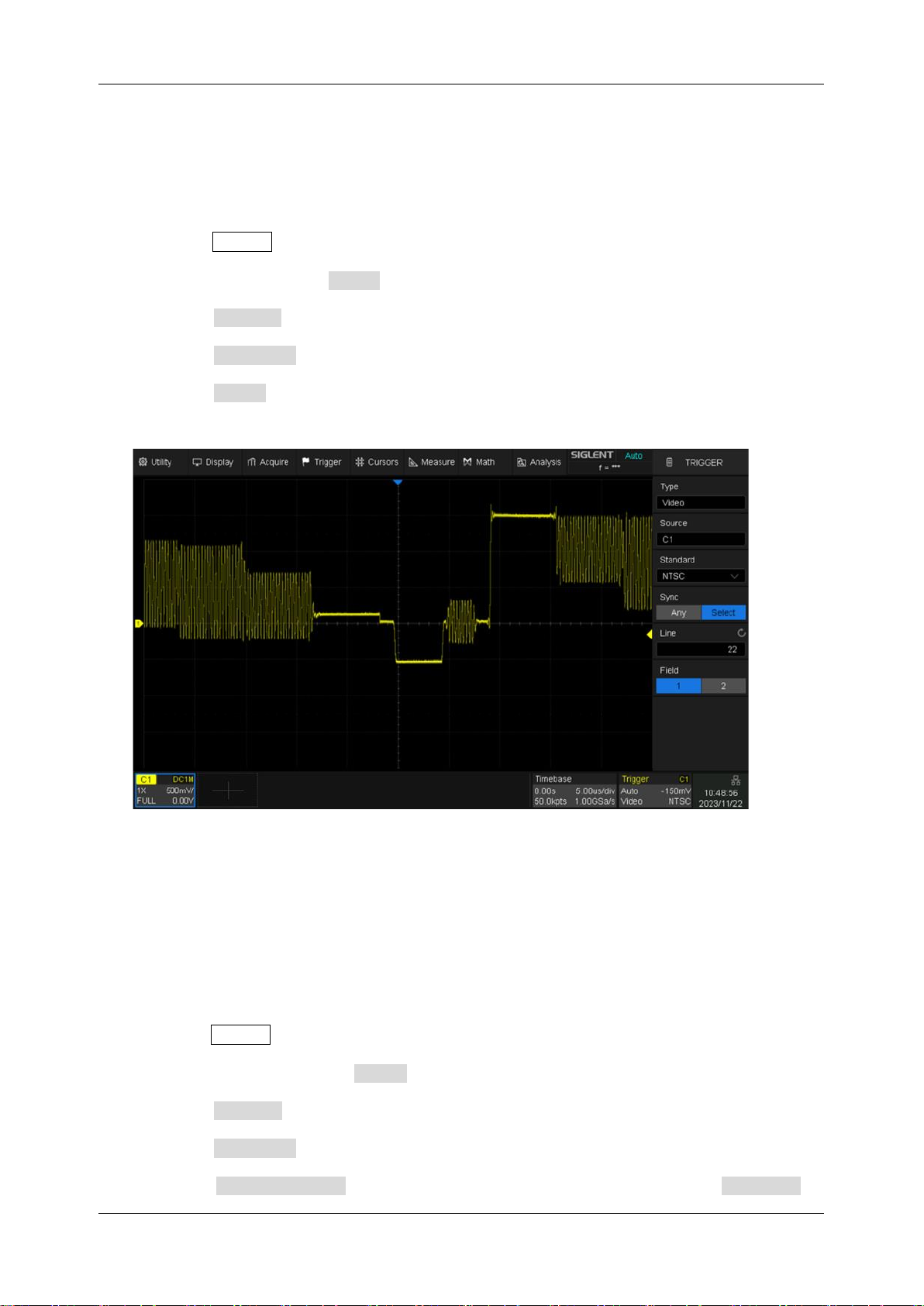
SDS1000X HD Series User Manual
80 i n t . s i g l e n t . c o m
Trigger on a Specific Line of Video
Video trigger requires that any analog channel can be used as the trigger source with a
synchronization amplitude greater than 1/2 grid. The example below sets to trigger on Field 1, Line
22 using the NTSC video standard.
1. Press the Setup button on the front panel to open the trigger menu.
2. In the trigger menu, touch Type and select "Video".
3. Touch the Source and select C1 as the trigger source.
4. Touch the Standard and select the "NTSC".
5. Touch the Sync and select the "Select" to make the Field and Line optional, then select "1" in
the "Field", and set the "Line" to "22" by using the universal knob or the virtual keypad.
Trigger on a Specific Line of Video (NTSC)
Use “Custom” to Trigger Video Signals
Custom video trigger supports video signals with frame rates of 25, 30, 50, and 60 Hz respectively,
and the specified row is within the range of 300 to 2000. The following describes how to trigger a
"Custom" video signal.
1. Press the Setup button on the front panel to open the trigger menu.
2. In the trigger menu, touch the Type , and select the "Video".
3. Touch the Source and select C1 as the trigger source.
4. Touch the Standard and select the "Custom".
5. Touch the Custom Setting to open the custom setting menu, and touch the Interlace to
Page 91
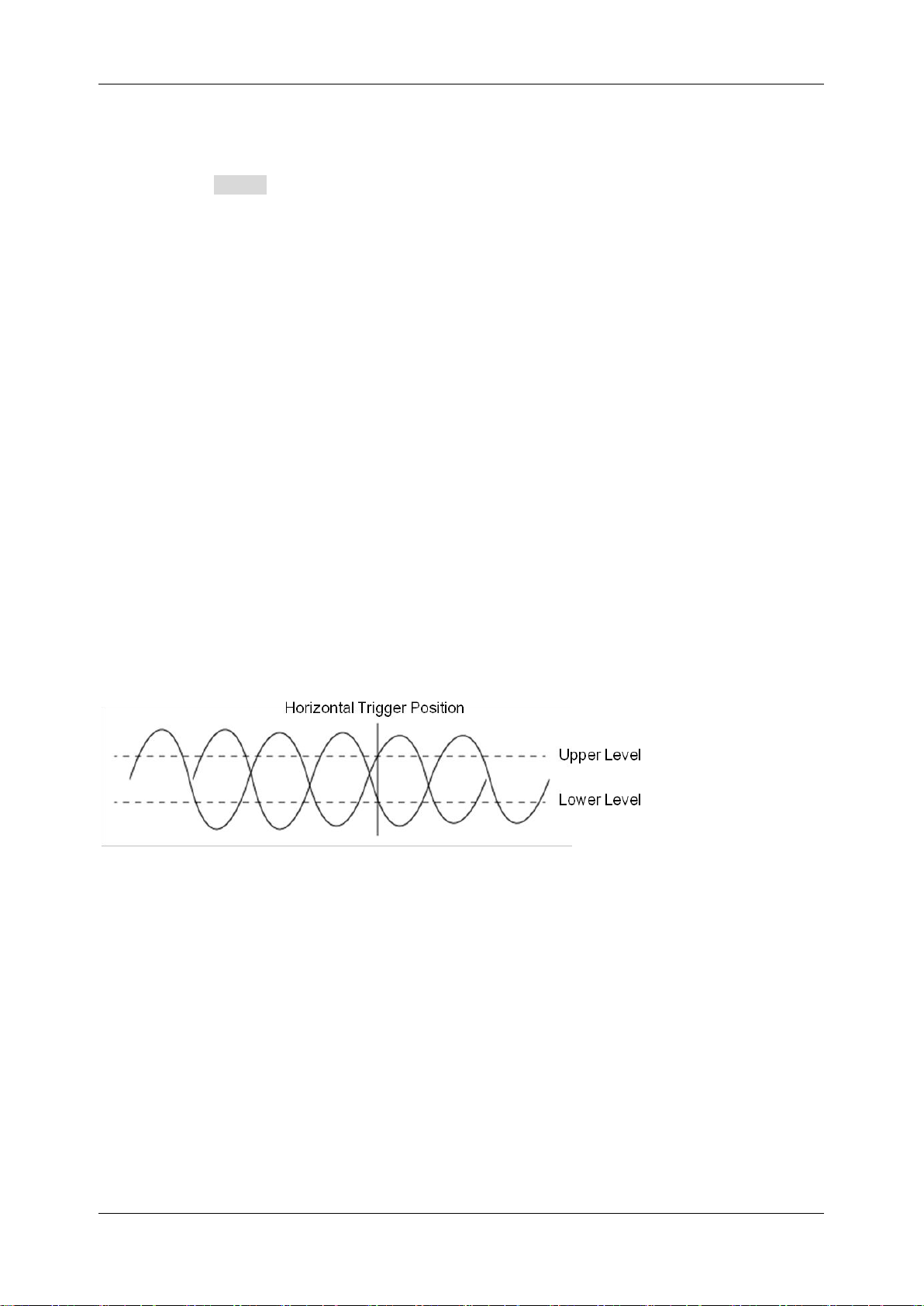
SDS1000X HD Series User Manual
int si glent.com 81
select the required interlace ratio (assuming that the interlace ratio is 8:1). Then set the frame
rate, select the number of lines and the number of fields.
6. Touch the Sync to select the synchronization mode for the input signal:
a) Select the "Any" mode, and the signal can be triggered on any line that meets the trigger
condition.
b) Select the "Select" mode, then set the specified line and the specified field to trigger the
signal. Assuming that the "Field" is set to 8, you can select any field from 1 to 8, and each
field can choose any line from 1 to 100.
15.5.6 Window Trigger
The window trigger is similar to the edge trigger, except that it provides an upper and a lower trigger
level. The instrument triggers when the input signal passes through the upper level or the lower level.
There are two kinds of window types: Absolute and Relative. They have different trigger level
adjustment methods. Under the Absolute window type, the lower and the upper trigger levels can be
adjusted separately. The relative window provides adjustment for the Center value to set the window
center and the Delta value to set the window range. In this mode, the lower and the upper trigger
levels always move together.
If the lower and the upper trigger levels are both within the waveform amplitude range, the
oscilloscope will trigger on both rising and falling edges.
If the upper trigger level is within the waveform amplitude range while the lower trigger level
is out of the waveform amplitude range, the oscilloscope will trigger on the rising edge only.
If the lower trigger level is within the waveform amplitude range while the upper trigger level
is out of the waveform amplitude range, the oscilloscope will trigger on the falling edge only.
To set window trigger via the Absolute window type
Refer to "Adjust Upper/Lower Level" in the section "Slope Trigger".
Page 92
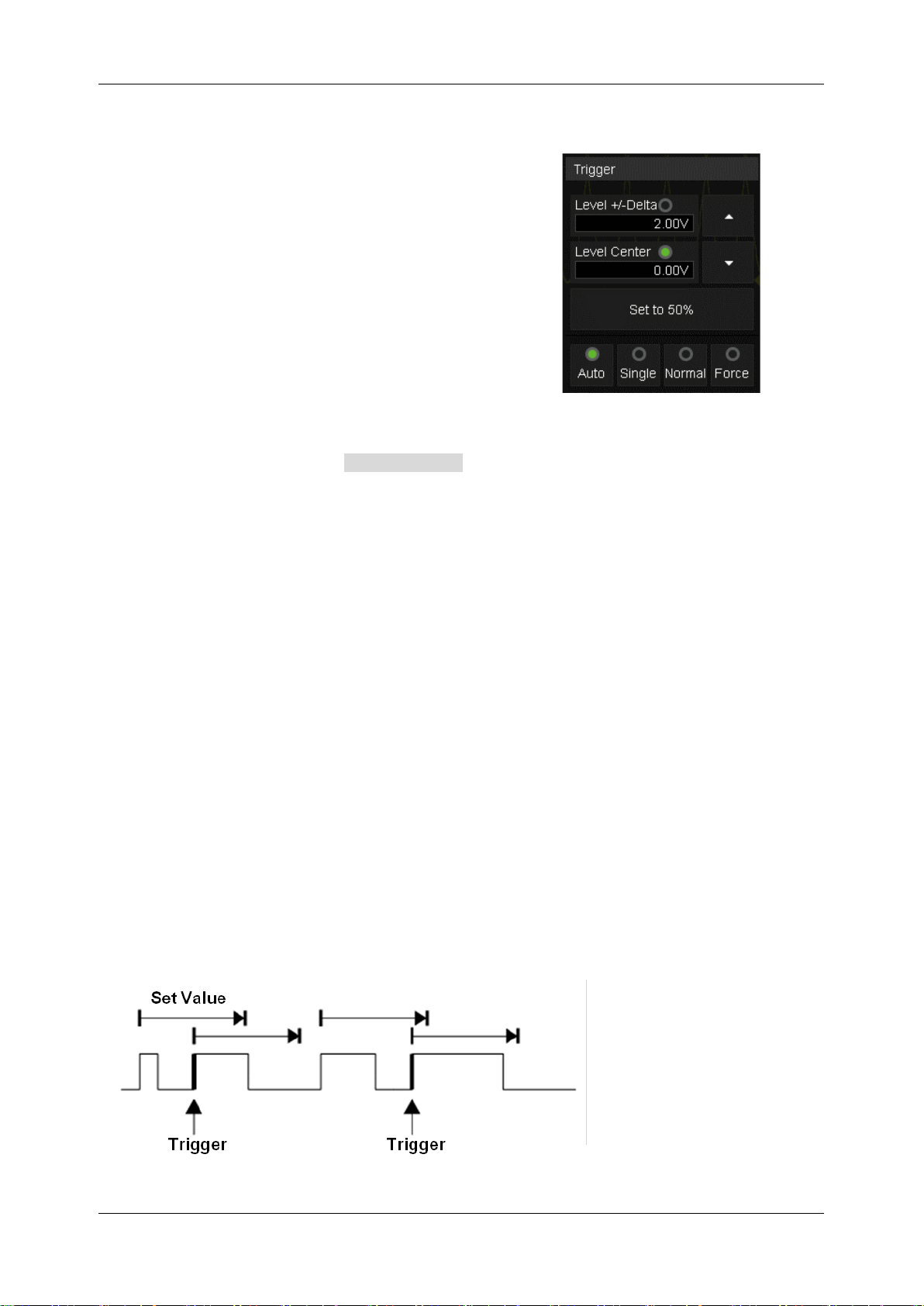
SDS1000X HD Series User Manual
82 i n t . s i g l e n t . c o m
To set window trigger via the Relative window type
When the window trigger type is set to "Relative",
touch the trigger descriptor box. The pop-up menu will
show two user-defined parameters: “Level +/-Delta"
and "Level Center".
The above two parameters can be set in the following two ways:
1. Select the parameter in the Level +/-Delta area of the quick menu, then set the parameter
value by the virtual keypad or the Level knob on the front panel. To set the center level is similar.
2. Directly use the Level knob on the front panel. Press the knob to switch between “Level +/-Delta"
and "Level Center", and rotate it to set values.
Note: “Level +/-Delta” represents half of the actual window area. For example, when the value is
200mV, it represents a range of ±200 mV, which is a 400mV window.
Holdoff, coupling, and noise reject can be set in window trigger, see the sections "Holdoff", "Trigger
Coupling" and "Noise Reject" for details.
15.5.7 Interval Trigger
Trigger when the time difference between the neighboring rising or falling edges meets the time limit
condition.
When the trigger condition is set as an interval between two neighboring rising edges and it is less
than the set time value, the trigger diagram is as follows:
Page 93
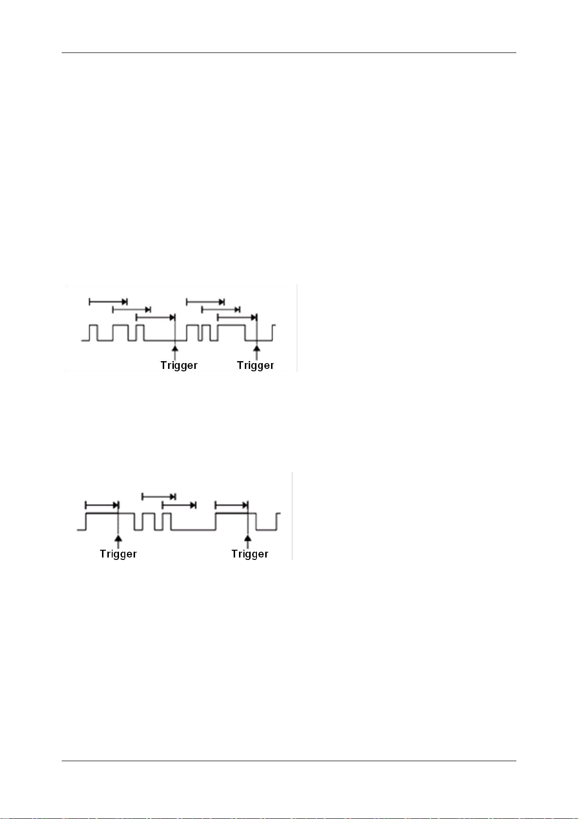
SDS1000X HD Series User Manual
int si glent.com 83
Trigger source, slope (rising, falling), limit range, and time value can be set in the trigger dialog box.
Holdoff, coupling, and noise reject can be set in interval trigger, see the sections "Holdoff", "Trigger
Coupling" and "Noise Reject" for details.
15.5.8 Dropout Trigger
Dropout trigger includes two types: Edge and State.
Edge
Trigger when the time interval (△T) from when the rising edge (or falling edge) of the input signal
passes through the trigger level to when the neighboring rising edge (or falling edge) passes through
the trigger level is greater than the set time, as shown in the figure below:
State
Trigger when the time interval (△T) from when the rising edge (or falling edge) of the input signal
passes through the trigger level to when the neighboring falling edge (or rising edge) passes through
the trigger level is greater than the set time, as shown in the figure below:
Trigger source, slope (rising, falling), dropout type, and time value can be set in the trigger dialog box.
Holdoff, coupling, and noise reject can be set in the dropout trigger, see the sections "Holdoff", "Trigger
Coupling" and "Noise Reject" for details.
15.5.9 Runt Trigger
Runt trigger looks for pulses that cross one threshold but not another as shown in the figure below:
Page 94
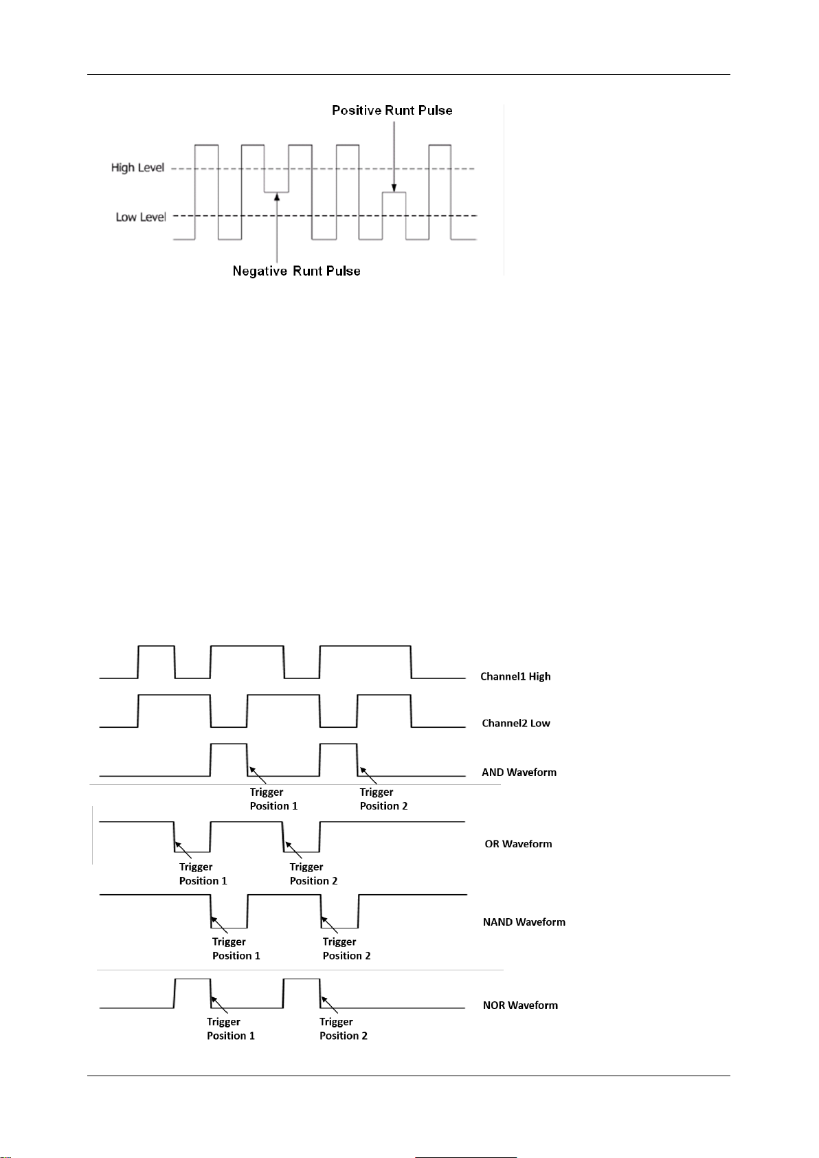
SDS1000X HD Series User Manual
84 i n t . s i g l e n t . c o m
A positive runt pulse across through the low level but not the high level.
A negative runt pulse across through the high level but not the low level.
Holdoff, coupling, and noise reject can be set in the runt trigger, see the sections "Holdoff", "Trigger
Coupling" and "Noise Reject" for details.
15.5.10 Pattern Trigger
The Pattern trigger identifies a trigger condition by looking for a specified pattern. The SDS1000X HD
provides 4 patterns: logical AND, OR, NAND and NOR combination of the channels. Each channel
can be set to "Low", "High" or "Don't Care". If all channels are set to "Don’t Care", the oscilloscope
will not trigger. The result after the logical operation is triggered from true to false, that is, triggers on
the falling edge of the combined waveform.
Page 95
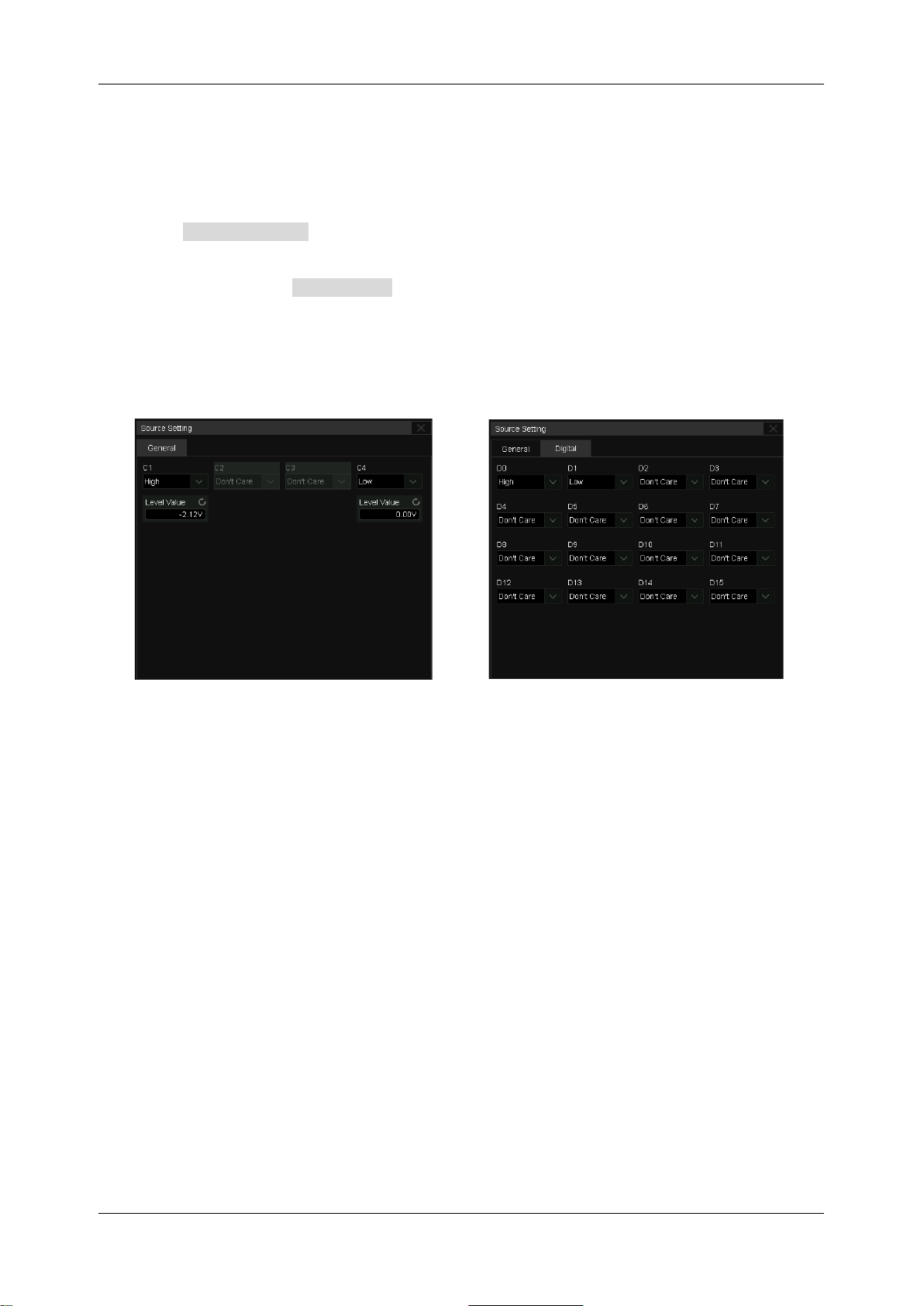
SDS1000X HD Series User Manual
int si glent.com 85
Logic (AND, OR, NAND, NOR), source, limit range, and time value can be set in the trigger dialog
box.
Source Setting
Touch the Source Setting area to recall the following dialog box and set up for each channel
separately. Each channel can be set to "Low", "High" or "Don't Care". The threshold can be
determined by setting the Level Value .
When digital channels are turned on, the logic state of the digital channel can also be set in the source
setting dialog box.
The logical setting of analog channels
The logical setting of digital channels
Limit Range
This setting is particularly useful to filter the hazard signals of combinational logic.
Holdoff can be set in pattern trigger, see the section "Holdoff" for details.
15.5.11 Qualified Trigger
The qualified trigger is an edge trigger after a user-defined qualified condition is satisfied. So a
qualified trigger has two sources; one is the source of the edge trigger, and the other is the qualified
source.
The qualified types include “State”, “State with Delay”, “Edge”, and “Edge with Delay”. When the type
is “State”, the oscilloscope triggers on the first edge when the qualified source is in the specified state
(High or Low). When the type is “State with Delay”, a time limit condition is also available.
Page 96
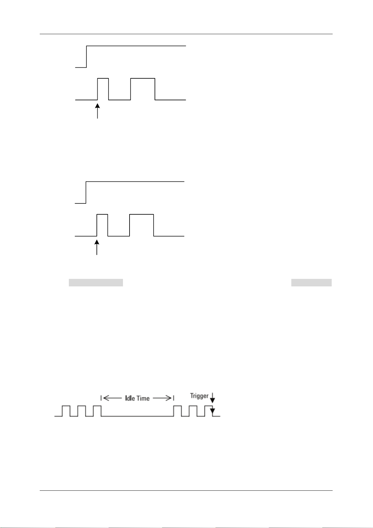
SDS1000X HD Series User Manual
86 i n t . s i g l e n t . c o m
Qualified
Source
Edge
Trigger
Source
Trigger
Position
Qualified State = High
Edge = Rising
When the type is “Edge”, the oscilloscope triggers at the first edge after the specified edge (Rising or
Falling) of the qualified source; when the type is “Edge with Delay”, a time limit condition is available.
Qualified
Source
Edge
Trigger
Source
Trigger
Position
Qualified Edge = Rising
Edge = Rising
Click the Qualified Setting region to set the qualified source and threshold; Click the Edge Setting
region to set the edge trigger source, threshold, and slope.
15.5.12 Nth Edge Trigger
Nth edge trigger is similar to an edge trigger with conditions. The trigger is satisfied after meeting the
user-defined idle time and edge number conditions. As shown in the figure below, when the idle time
between the pulse trains is greater than the specified idle time, it is triggered on the third falling edge
of the pulse train.
Trigger source, slope (rising, falling), idle time, and edge number can be set in the trigger dialog box.
Holdoff, coupling, and noise reject can be set in the Nth edge trigger, see the sections "Holdoff",
"Trigger Coupling" and "Noise Reject" for details.
Page 97
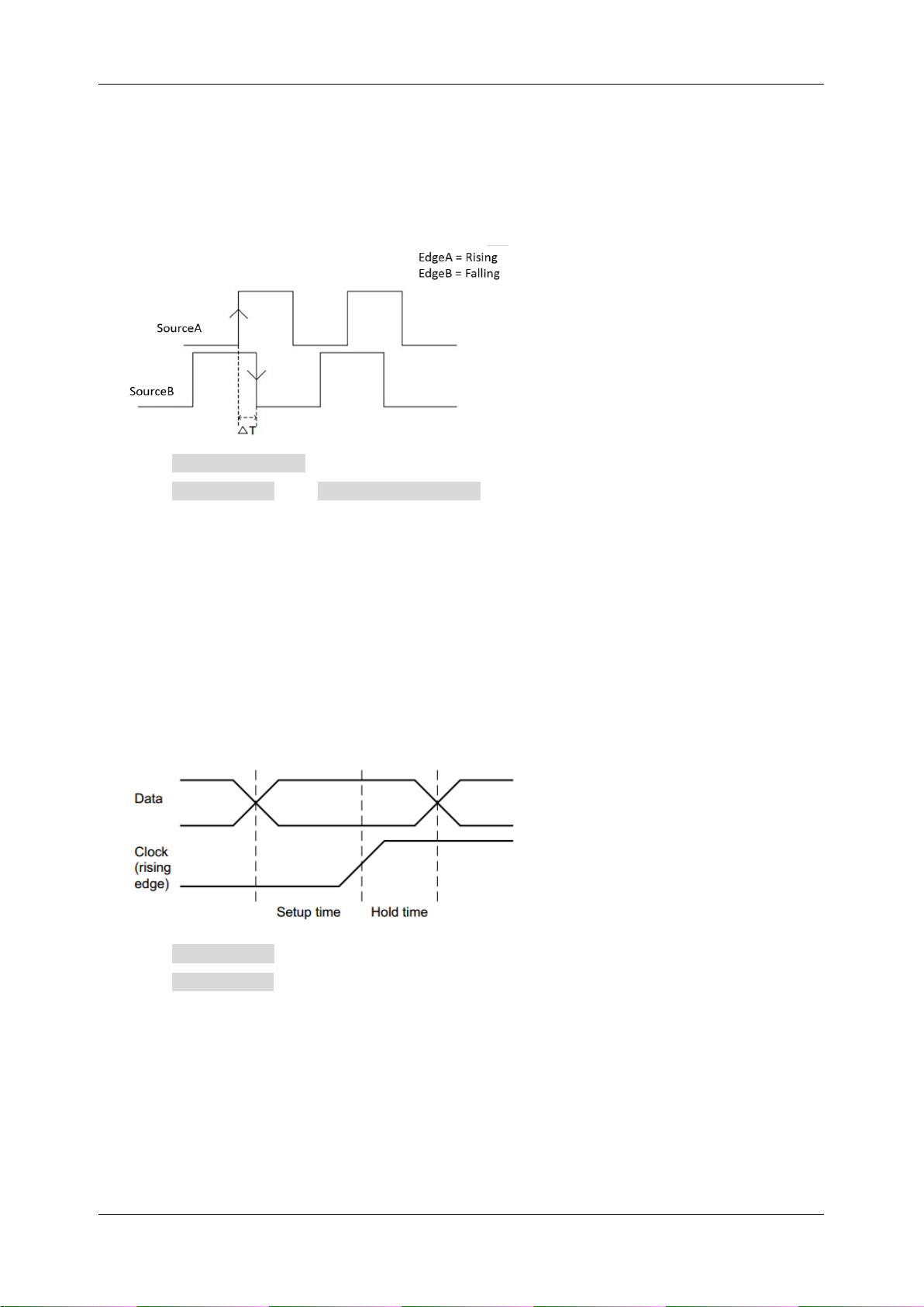
SDS1000X HD Series User Manual
int si glent.com 87
15.5.13 Delay Trigger
A delay trigger is true when the edge of source B occurs after meeting the set conditions of source A
and a user-defined delay time. The setting of source A is similar to that of the pattern trigger and can
be used for logical "and" combination of multiple channels.
Click the SourceB Setting region to set the edge trigger source, threshold, and slope.
Click the Limit Range and Upper / Lower Value region to set the delay time condition.
15.5.14 Setup/Hold Trigger
The clock and data sources need to be set in the setup/hold trigger setting. The set-up time starts
when the data signal crosses the trigger level and ends when the specified clock edge arrives. The
holding time starts when the specified clock edge arrives and ends when the data signal crosses the
trigger level again (as shown in the figure below). When the set-up time or hold time meets the preset
time limit conditions, the oscilloscope will trigger.
Click the CLK Setting region to set the clock source, threshold, and slope.
Click the Data Setting region to set the data source, threshold, and state.
15.5.15 Serial Trigger
Refer to chapter "Serial Trigger and Decode" for detailed information.
Page 98
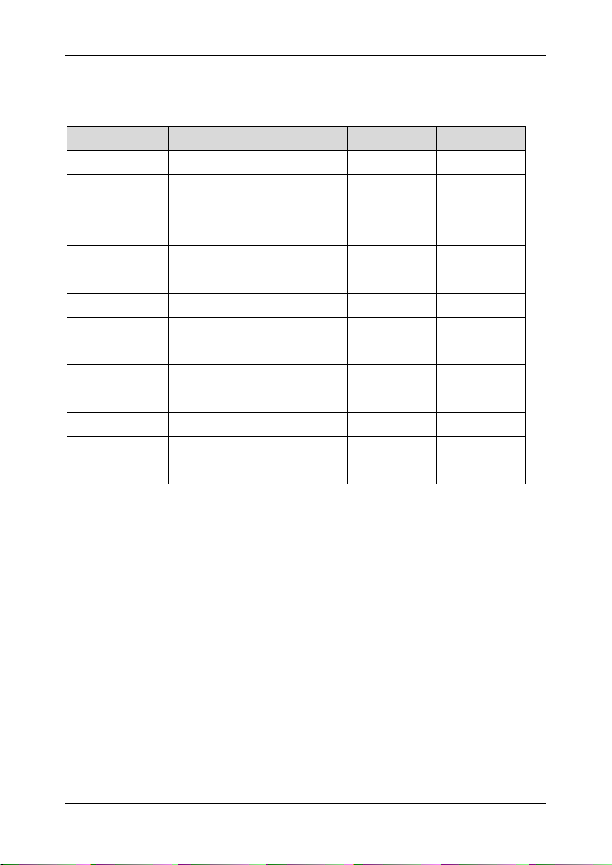
SDS1000X HD Series User Manual
88 i n t . s i g l e n t . c o m
15.6 Trigger Source
The trigger sources supported by each trigger type are different. See the table below for details:
Trigger Type
C1~C4
EXT, EXT/5
AC Line
D0~D15
Edge
√ √ √
√
Slope
√ × × × Pulse
√ × ×
√
Video
√ × ×
×
Window
√ × × × Interval
√ × ×
√
Dropout
√ × ×
√
Runt
√ × × × Pattern
√ × ×
√
Serial
√ × ×
√
Qualified
√ × ×
×
Nth Edge
√ × ×
×
Delay
√ × ×
×
Setup/Hold
√ × ×
×
15.7 Holdoff
Holdoff is an additional condition for triggers and can be used to stabilize the triggering of complex
waveforms (such as a pulse series). It can be set to time.
Holdoff by Time
Holdoff time is the amount of time that the oscilloscope waits before re-arming the trigger circuitry.
The oscilloscope will not trigger until the holdoff time expires.
Use the holdoff to trigger on repetitive waveforms that have multiple edges (or other events) between
waveform repetitions. You can also use holdoff to trigger on the first edge of a burst when you know
the minimum time between bursts.
For example, to achieve a stable trigger on the repetitive pulses shown in the figure below set the
holdoff time (t) to 200ns<t<600ns.
Page 99
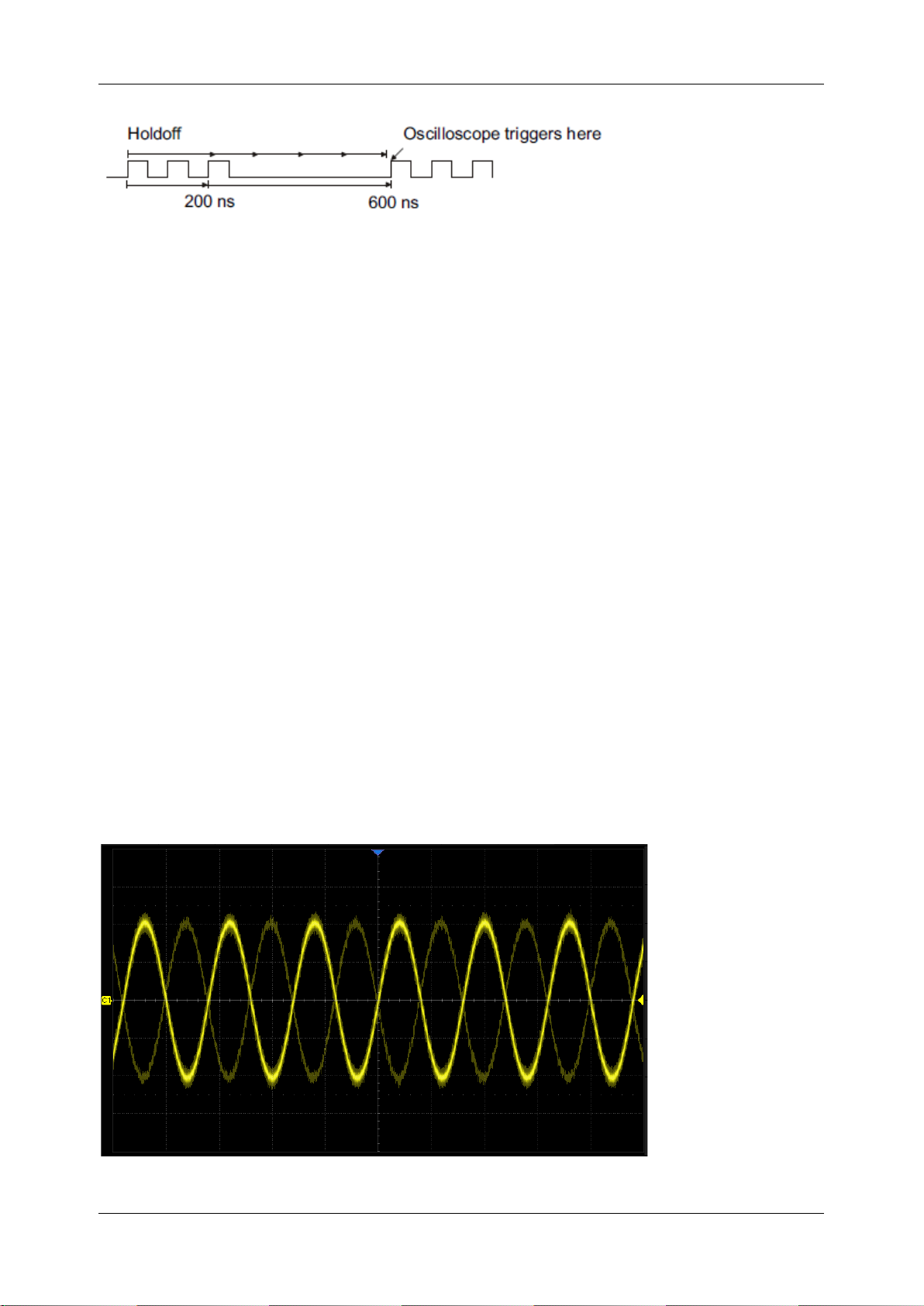
SDS1000X HD Series User Manual
int si glent.com 89
15.8 Trigger Coupling
The coupling setting of a trigger is only valid when the trigger source is C1~C4, EXT, or EXT/5.
DC: All of the signal’s frequency components are coupled to the trigger circuit for high-frequency
bursts or where the use of AC coupling would shift the effective trigger level.
AC: The signal is capacitively coupled. DC levels are rejected. See the datasheet for details of
the cut-off frequency.
HFR: Signals are DC coupled to the trigger circuit and a low-pass filter network attenuates high
frequencies (used for triggering on low frequencies). See the datasheet for details of the cut-off
frequency.
LFR: The signal is coupled through a capacitive high-pass filter network, DC is rejected and low
frequencies are attenuated. For stable triggering on medium to high-frequency signals. See the
datasheet for details of the cut-off frequency.
15.9 Noise Reject
Noise Reject adds additional hysteresis to the trigger circuitry. By increasing the trigger hysteresis,
the noise immunity becomes better but the trigger sensitivity degrades.
Noise Reject = Off
Page 100
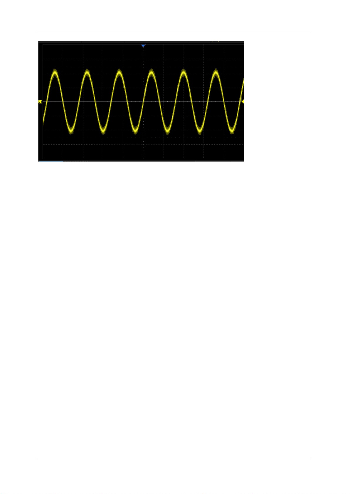
SDS1000X HD Series User Manual
90 i n t . s i g l e n t . c o m
Noise Reject = On
 Loading...