

SIGLENT SDS1000X-E Series User Manual
User Manual
SDS1000X-E Series Digital
oscilloscope
UM0101X-E03A
SIGLENT TECHNOLOGIES CO., LTD.

SIGLENT
Copyright and Declaration
Copyright
SIGLENT TECHNOLOGIES CO., LTD. All Rights Reserved.
Trademark Information
SIGLENT is the registered trademark of SIGLENT TECHNOLOGIES CO., LTD.
Declaration
SIGLENT products are protected by patent law in and outside of P.R.C.
SIGLENT reserves the right to modify or change parts of or all the specifications or pricing
policies at company’s sole decision.
Information in this publication replaces all previously corresponding material.
Any way of copying, extracting or translating the contents of this manual is not allowed
without the permission of SIGLENT.
Product Certification
SIGLENT guarantees this product conforms to the national and industrial stands in China
and other international stands conformance certification is in progress.
Contact Us
If you have any problem or requirement when using our products, please contact
SIGLENT TECHNOLOGIES CO., LTD
Add:3//F, Bldg No.4, Antongda Industrial Zone, 3rd Liuxian Road, Bao’an District,
Shenzhen, 518101, P.R.China
Tel:400-878-0807
E-mail:sales@siglent.com
http://www.siglent.com
User Manual I

SIGLENT
Safety Information
General Safety Summary
Carefully read the following safety precautions to avoid any personal injury or
damage to the instrument and any products connected to it. To avoid potential
hazards, please use the instrument as specified.
Use Proper Power Line
Only the power cord designed for the instrument and authorized by local country could be
used.
Ground the Instrument
The instrument is grounded through the protective earth conductor of the power line. To
avoid electric shock, please make sure the instrument is grounded correctly before
connecting its input or output terminals.
Connect the Signal Wire Correctly
The potential of the signal wire is equal to the earth, so do not connect the signal wire to a
high voltage.
Look Over All Terminals‟ Ratings
To avoid fire or electric shock, please look over all ratings and sign instruction of the
instrument. Before connecting the instrument, please read the manual carefully to gain
more information about the ratings.
Use Proper Overvoltage Protection
Make sure that no overvoltage (such as that caused by a thunderstorm) can reach the
product, or else the operator might expose to danger of electrical shock.
Electrostatic Prevention
Operate in an electrostatic discharge protective area environment to avoid damages
induced by static discharge. Always ground both the internal and external conductors of
the cable to release static before connecting.
Keep Well Ventilation
Inadequate ventilation may cause increasing of temperature, which will eventually
damage the instrument. So keep well ventilation and inspect the intake and fan regularly.
Avoid Circuit or Components Exposed
Do not touch exposed contacts or components when the power is on.
II User Manual

SIGLENT
Use proper Fuse
Use only the specified fuse.
Do Not Operate Without Covers
Do not operate the instrument with covers or panels removed.
Do Not Operate With Suspected Failures.
If you suspect damage occurs to the instrument, have it inspected by qualified service
personnel before further operations. Any maintenance, adjustment or replacement
especially to circuits or accessories must be performed by SIGLENT authorized
personnel.
Do Not Operate in Wet Conditions.
In order to avoid short circuiting to the interior of the device or electric shock, please do
not operate in a humid environment.
Do Not Operate in an Explosive Atmosphere.
In order to avoid damages to the device or personal injuries, it is important to operate the
device away from an explosive atmosphere.
Keep Product Surfaces Clean and Dry.
To avoid the influence of dust and/or moisture in air, please keep the surface of device
clean and dry.
Handling Safety
Please handle with care during transportation to avoid damages to buttons, knob
interfaces and other parts on the panels.
Only probe assemblies which meet the manufacturer’s specifications shall be used.
When use 2X/…/10000X probe assemblies, the probe assemblies shall be insulated from
the measured circuits by double or reinforced insulation.
All probe assemblies should meet the requirements of UL 61010-031 and
CAN/CSA-C22.2 No. 61010-031-07.
Not to position the equipment so that it is difficult to operate the disconnecting device
(detachable plug).
If the equipment is used in a manner not specified by the manufacturer, the protection
provided by the equipment may be impaired
User Manual III
SIGLENT
Terms in this Manual. These terms may appear in this manual:
WARNING
Warning statements indicate the conditions or practices that could
result in injury or loss of life.
CAUTION
Caution statements indicate the conditions or practices that could
result in damage to this product or other property.
Safety Terms and Symbols
Terms on the product. These terms may appear on the product:
DANGER Indicates direct injuries or hazards that may happen.
WARNING Indicates potential injuries or hazards that may happen.
CAUTION Indicates potential damages to the instrument or other property that may
happen.
Symbols on the product. These symbols may appear on the product:
Hazardous protective Earth Warning Test Power Switch
Voltage Terminal Ground
If find such symbols on the product, consult the manual to find out the nature of the
potential hazard and the actions which have to be taken
IV User Manual

SIGLENT
Measurement Category
Measurement Categories
This oscilloscope can make measurements in other circuits that are not directly connected
to mains.
WARNING
This oscilloscope can only be used for measurements within its specified
measurement categories.
Not to use the product for measurements within other measurement
categories, such as CAT II, CAT III, CAT IV.
Not to use the equipment for measurements on mains circuits
Measurement Category Definitions
Measurement category II is for measurements performed on circuits directly connected to
the low voltage installation. Examples are measurements on household appliances,
portable tools and similar equipment.
Measurement category III is for measurements performed in the building installation.
Examples are measurements on distribution boards, circuit-breakers, wiring, including
cables, bus-bars, junction boxes, switches, socket-outlets in the fixed installation, and
equipment for industrial use and some other equipment, for example. Stationary motors
with permanent connection to the fixed installation.
Measurement category IV is for measurements performed at the source of the low-voltage
installation. Examples are electricity meters and measurements on primary over current
protection devices and ripple control units.
User Manual V
SIGLENT
Working Environment
Temperature
Operating: 10℃ to +40℃
Non-operation:-20℃ to +70℃
Humidity
Under +35℃:≤90% relative humidity
+35℃ to +40℃: ≤60% relative humidity
WARNING
To avoid short circuit inside the instrument or electric shock, please do not
operate in humid environment.
Altitude
Operating: less than 3 Km
Non-operation: less than 15 Km
Degree of protection
IP20
Installation (overvoltage) Category
This product is powered by mains conforming to installation (overvoltage) category II.
WARNING
Make sure that no overvoltage (such as that caused by thunderbolt) can reach
the product, or else the operator might expose to danger of electric shock.
Installation (overvoltage) Category Definitions
Installation (overvoltage) category I refers to signal level which is applicable to equipment
measurement terminals connected to the source circuit. In these terminals, precautions
are done to limit the transient voltage to the corresponding low level.
Installation (overvoltage) category II refers to the local power distribution level which is
applicable to equipment connected to the AC line (AC power).
VI User Manual

SIGLENT
Ventilation Requirement
This oscilloscope uses fan to force cooling. Please make sure that the air intake and
exhaust areas are free from obstructions and have free air. When using the oscilloscope
in a bench-top or rack setting, provide at least 10 cm clearance beside, above and behind
the instrument for adequate ventilation.
WARNING
Inadequate ventilation may cause temperature increase which would damage
the instrument. So please keep the instrument well ventilated during operation
and inspect the intake and fan regularly.
User Manual VII

SIGLENT
General Care and Cleaning
Care
Do not store or leave the instrument in direct sunshine for long periods of time.
WARNING
To avoid damages to the instrument or probe, please do not leave them in fog,
liquid, or solvent.
Cleaning
Please perform the following steps to clean the instrument and probe regularly according
to its operating conditions.
1. Disconnect the instrument from all power sources, and then clean it with a soft wet
cloth.
2. Clean the loose dust on the outside of the instrument and probe with a soft cloth.
When cleaning the LCD, take care to avoid scarifying it.
WARNING
To avoid damages to the surface of the instrument and probe, please do not
use any corrosive liquid or chemical cleanser.
WARNING
Make sure that the instrument is completely dry before restarting it to avoid
short circuits or personal injuries.
VIII User Manual

Document Overview
Quick Start
Provide information about preparations before
using the instrument and a brief introduction of
the instrument.
To Set the Vertical System
Introduce the functions of the vertical system of
the oscilloscope.
To Set the Horizontal System
Introduce the functions of the horizontal system
of the oscilloscope.
To Set the Sample System
Introduce the functions of the sample system of
the oscilloscope.
To Trigger the Oscilloscope
Introduce the trigger mode, trigger coupling,
trigger hold off, external trigger and various
trigger types of the oscilloscope.
Serial Trigger
Introduce how to trigger the input signal.
To Save Reference Waveform
Introduce how to save and display REF
waveform.
To Make Math Operation
Introduce the math operation function of the
oscilloscope.
To Make Cursor Measurements
Introduce how to use cursors to make
measurements.
To Make Measurements
Introduce how to use measure function to
measure the waveform parameters.
Display Setting
Introduce how to set the display of the
oscilloscope.
Save and Recall
Introduce how to save and recall the
measurement result and the setting of the
oscilloscope.
System Setting
Introduce how to set the system setup.
Default
Introduce the Default setup of the oscilloscope
Troubleshooting
Introduce how to deal with common failures of
the oscilloscope.
This manual introduces how to use the digital oscilloscope in details.
SIGLENT
User Manual IX

SIGLENT
Table of Content
Copyright and Declaration ............................................................................................................. I
Safety Information .......................................................................................................................... II
General Safety Summary ........................................................................................................... II
Safety Terms and Symbols ....................................................................................................... IV
Measurement Category ........................................................................................................... V
Working Environment ............................................................................................................. VI
Ventilation Requirement ........................................................................................................ VII
General Care and Cleaning .................................................................................................... VIII
Document Overview ...................................................................................................................... IX
Quick Start ....................................................................................................................................... 1
General Inspection .................................................................................................................... 2
Appearance and Dimensions .................................................................................................... 3
To Prepare the Oscilloscope for Use ......................................................................................... 5
To Adjust the Supporting Legs ...................................................................................... 5
To Connect to Power Supply ........................................................................................ 6
Power-on Inspection ...................................................................................................... 7
To Connect the Probe .................................................................................................... 7
Function Inspection ........................................................................................................ 8
Probe Compensation ..................................................................................................... 9
Front Panel Overview .................................................................................................. 10
Rear Panel Overview ................................................................................................... 12
Front Panel Function Overview ............................................................................................... 14
Horizontal ....................................................................................................................... 14
Vertical ........................................................................................................................... 15
Trigger ............................................................................................................................ 16
Run Control ................................................................................................................... 17
Universal Knob .............................................................................................................. 18
Menu ............................................................................................................................... 19
Help ......................................................................................................................................... 21
User Interface .......................................................................................................................... 22
To Use the Security Lock ......................................................................................................... 24
To Set the Vertical System ......................................................................................................... 25
To Enable the Channel ............................................................................................................. 26
To Adjust the Vertical Scale ..................................................................................................... 27
To Adjust the Vertical Position ................................................................................................ 27
To Specify Channel Coupling ................................................................................................... 28
To Specify Bandwidth Limit ..................................................................................................... 28
To Specify Probe Attenuation Factor ....................................................................................... 29
To Specify channel Input Impedance ...................................................................................... 29
To Specify Amplitude Unit ....................................................................................................... 30
To Specify Deskew ................................................................................................................... 30
To Invert a Waveform .............................................................................................................. 30
X User Manual

SIGLENT
Set the Horizontal System .......................................................................................................... 31
Adjust the Horizontal Scale ..................................................................................................... 32
Adjust Trigger Delay ................................................................................................................ 33
Set the Roll mode .................................................................................................................... 34
Use the Zoom Function ........................................................................................................... 35
To Set the Sample System ......................................................................................................... 36
Run Control ............................................................................................................................. 37
Overview of Sampling ............................................................................................................. 38
Sampling Theory........................................................................................................... 38
Sample Rate.................................................................................................................. 39
Oscilloscope Bandwidth and Sample Rate .............................................................. 40
Select Memory Depth ............................................................................................................. 41
Select Sampling Mode ............................................................................................................. 42
Select Waveform Interpolation Method ................................................................................. 43
Select Acquisition Mode ......................................................................................................... 45
Normal ............................................................................................................................ 45
Peak Detect ..................................................................................................................... 46
Average............................................................................................................................ 47
High Resolution ............................................................................................................... 48
Change the Horizontal Format ................................................................................................ 49
Use Sequence Mode ............................................................................................................... 50
To Trigger the Oscilloscope ........................................................................................................ 52
Trigger Source ......................................................................................................................... 54
Trigger Mode ........................................................................................................................... 55
Trigger Level ............................................................................................................................ 56
Trigger Coupling ...................................................................................................................... 57
Trigger Holdoff ........................................................................................................................ 58
Noise Rejection ....................................................................................................................... 59
Trigger Type ............................................................................................................................. 61
Edge Trigger .................................................................................................................. 62
Slope Trigger ................................................................................................................. 63
Pulse Trigger ................................................................................................................. 65
Video Trigger ................................................................................................................. 67
Window Trigger ............................................................................................................. 70
Interval Trigger .............................................................................................................. 73
DropOut Trigger ............................................................................................................ 75
Runt Trigger ................................................................................................................... 77
Pattern Trigger .............................................................................................................. 79
Serial trigger and decode ............................................................................................................ 81
I2C Trigger and Serial Decode ................................................................................................. 82
Setup for I2C Signals ........................................................................................................ 82
I2C Triggering................................................................................................................... 84
I2C Serial Decode ............................................................................................................ 88
SPI Triggering and Serial Decode ..................................................................................................... 90
User Manual XI

SIGLENT
Setup for SPI Signals ................................................................................................... 90
SPI Triggering ............................................................................................................... 93
SPI Serial Decode ........................................................................................................ 95
UART/RS232 Triggering and Serial Decode ..................................................................................... 97
Setup for UART/RS232 Signals ................................................................................. 97
UART/RS232 Triggering.................................................................................................... 99
UART/RS232 Serial Decode ........................................................................................... 101
CAN Trigger and Serial Decode ............................................................................................. 103
Setup for CAN Signals .................................................................................................... 103
CAN Triggering ............................................................................................................... 105
CAN Serial Decode......................................................................................................... 107
LIN Triggering and Serial Decode .......................................................................................... 109
Setup for LIN Signals ................................................................................................. 109
LIN Triggering ................................................................................................................ 110
LIN Serial Decode .......................................................................................................... 112
To Save Reference Waveform.................................................................................................. 114
To Save REF Waveform to Internal Memory ......................................................................... 115
To Display REF Waveform ...................................................................................................... 115
To Adjust REF Waveform Display ........................................................................................... 116
To Clear REF Waveform Display ............................................................................................. 117
To Make Math Operation ........................................................................................................... 118
Units for Math Waveforms .................................................................................................... 118
Math Operators ..................................................................................................................... 119
Addition or Subtraction ................................................................................................. 119
Multiplication and Division ........................................................................................... 120
FFT Operation ................................................................................................................ 121
Math Function Operation ...................................................................................................... 124
Differentiate .................................................................................................................. 124
Integrate ........................................................................................................................ 125
Square Root ................................................................................................................... 126
To Make Cursors Measurements ............................................................................................. 128
X Cursors ............................................................................................................................... 128
Y Cursors ................................................................................................................................ 128
To Make Cursor Measurements ............................................................................................ 129
To Make Measurements ................................................................................................................ 130
Type of Measurement ........................................................................................................... 131
Voltage Measurements ................................................................................................. 131
Time Measurements ..................................................................................................... 133
Delay Measurements .................................................................................................... 134
To Make Automatic Measurement ........................................................................................ 135
To Clear Measurement Parameters ....................................................................................... 137
To Make All Measurement .................................................................................................... 137
Display Setting ............................................................................................................................... 138
To Set Display Type ................................................................................................................ 139
XII User Manual

SIGLENT
To Set Color Display ............................................................................................................... 140
To Set and Clear Persistence ................................................................................................. 140
To clear the display ................................................................................................................ 141
To Select Grid Type ................................................................................................................ 142
To Adjust Waveform Intensity ............................................................................................... 142
To Adjust Grid Brightness ...................................................................................................... 143
To Adjust Transparence ......................................................................................................... 143
Save and Recall .............................................................................................................................. 144
Save Type ............................................................................................................................... 145
Internal Save and Recall ........................................................................................................ 147
External save and recall ......................................................................................................... 148
Disk Management ................................................................................................................. 151
To Create a New File or Folder ...................................................................................... 152
To delete a file or folder ................................................................................................ 153
Digital Channels(Option) ........................................................................................................... 154
To Connect the Digital Probes to the Device-under-test ....................................................... 155
Acquiring Waveform Using the Digital Channels ................................................................... 156
To Change the Display Type of the Digital Channels ............................................................. 156
To Switch a Single Channel On or Off .................................................................................... 157
To Switch All Digital Channels On or Off ................................................................................ 157
To Change the Logic Threshold for Digital Channels ............................................................. 158
To Reposition a Digital Channel ............................................................................................. 158
To Display Digital Channels as a Bus ...................................................................................... 159
System Function Setting ................................................................................................................ 160
To View the System Status .................................................................................................... 161
To Do Self Calibration ............................................................................................................ 162
To Enable or Disable the Sound ............................................................................................ 163
To Specify the Language ........................................................................................................ 163
To Do Pass/Fail Test ............................................................................................................... 164
To Set and Perform Pass/Fail Test .................................................................................. 165
To Save and Recall Test Mask ........................................................................................ 166
Arbitrary Waveform Generator(Option) ............................................................................... 168
Output ........................................................................................................................... 169
Wave ............................................................................................................................... 169
Setting ........................................................................................................................... 171
Systems ......................................................................................................................... 173
Remove Device .............................................................................................................. 174
IO Set ..................................................................................................................................... 175
To Set the USB Device ................................................................................................... 175
To Set the LAN ............................................................................................................... 176
To Set the WLAN (Option) ............................................................................................. 177
To Set Aux Output ......................................................................................................... 178
To Use the Web Server .......................................................................................................... 179
To Update Firmware and Configuration ................................................................................ 180
User Manual XIII

SIGLENT
Do Self Test ............................................................................................................................ 181
Screen Test .................................................................................................................... 181
Keyboard Test ................................................................................................................ 182
LED Test ......................................................................................................................... 183
To specify Screen Saver Time ................................................................................................ 184
To Use the Expand Setting ..................................................................................................... 185
To Use the Power On Line ..................................................................................................... 185
Option Management ............................................................................................................. 186
Search ............................................................................................................................................ 188
Setting ................................................................................................................................... 188
Results ................................................................................................................................... 189
Navigate ........................................................................................................................................ 191
Time navigate ........................................................................................................................ 191
History frame navigate .......................................................................................................... 191
Search event navigate ........................................................................................................... 191
Bode Plot ....................................................................................................................................... 193
Perform Bode Plot application .............................................................................................. 193
Setting ................................................................................................................................... 193
To Use the History Function .......................................................................................................... 196
Factory Setup ................................................................................................................................ 198
Troubleshooting ............................................................................................................................ 202
XIV User Manual

Content of Figure
Figure 1 Front View (2-channel scope) ..................................................................................... 3
Figure 2 Top View (2-channel scope) ........................................................................................ 3
Figure 3 Front View (4-channel scope) ..................................................................................... 4
Figure 4 Top View (4-channel scope) ........................................................................................ 4
Figure 5 Adjust the Supporting Legs ......................................................................................... 5
Figure 6 To Connect to Power Supply ....................................................................................... 6
Figure 7 Function Inspection ..................................................................................................... 8
Figure 8 2-channel Scope Front Panel Overview ..................................................................... 10
Figure 9 4-channel Scope Front Panel Overview ..................................................................... 11
Figure 10 2-channel Scope Rear panel Overview .................................................................... 12
Figure 11 4-channel Scope Rear panel Overview .................................................................... 13
Figure 12 Help Message .......................................................................................................... 21
Figure 13 User Interface .......................................................................................................... 22
Figure 14 To Use the Security Lock ...................................................................................... 24
Figure 15 Display Type Set to Dots .......................................................................................... 43
Figure 16 x Interpolation ......................................................................................................... 44
Figure 17 Sinx/x Interpolation.............................................................................................. 44
Figure 18 Acquisition System .................................................................................................. 45
Figure 19 Pulse With 0.1% Duty, Normal Mode .................................................................. 46
Figure 20 Pulse With 0.1% Duty, Peak Detect Mode .............................................................. 46
Figure 21 With Random Noise, Normal Mode........................................................................ 47
Figure 22 With Random Noise, Average Mode ....................................................................... 48
Figure 23 SEQUENCE Function Menu ..................................................................................... 50
Figure 24 HISTORY Function Menu ......................................................................................... 50
Figure 25 Turn off the Noise Reject ......................................................................................... 59
Figure 26 Turn on the Noise Reject ......................................................................................... 60
Figure 27 Edge Trigger ............................................................................................................. 62
Figure 28 Slope Trigger ............................................................................................................ 64
Figure 29 Pulse Trigger ............................................................................................................ 66
Figure 30 Video Trigger ........................................................................................................... 69
Figure 31 Absolute Window Trigger........................................................................................ 71
Figure 32 Relative Window Trigger ......................................................................................... 72
Figure 33 Interval Trigger ........................................................................................................ 74
Figure 34 Edge DropOut Trigger .............................................................................................. 76
Figure 35 State DropOut Trigger ............................................................................................. 77
Figure 36 Runt Trigger ............................................................................................................. 78
Figure 37 Pattern Trigger ......................................................................................................... 80
Figure 38 I2C SINGAL Menu .................................................................................................... 82
Figure 39 I2C Decode Menu .................................................................................................... 88
Figure 40 SINGAL Menu .......................................................................................................... 90
Figure 41 CLK Menu ................................................................................................................ 91
SIGLENT
User Manual XV

SIGLENT
Figure 42 MISO Menu ............................................................................................................. 91
Figure 43 MOSI Menu ............................................................................................................. 91
Figure 44 SPI TRIG SET Menu ............................................................................................... 93
Figure 45 UART SIGNAL Menu ................................................................................................ 97
Figure 46 Reference Waveform ............................................................................................. 116
Figure 47 FFT Waveform in Split Mode ................................................................................. 123
Figure 48 Differential Function Operation ............................................................................ 125
Figure 49 Integral without Offset .......................................................................................... 126
Figure 50 Integral with Offset ............................................................................................... 126
Figure 51 Square Root ........................................................................................................... 127
Figure 52 Measure Pulse Width ............................................................................................ 129
Figure 53 Voltage Measurements ......................................................................................... 131
Figure 54 Overshoot .............................................................................................................. 132
Figure 55 Preshoot ................................................................................................................ 132
Figure 56 Time Measurements ............................................................................................. 133
Figure 57 Select the Measurement Parameter ..................................................................... 135
Figure 58 Added the Measurement ...................................................................................... 136
Figure 59 All Parameters Measurement ............................................................................... 137
Figure 60 Vectors Display ...................................................................................................... 139
Figure 61 Dots Display........................................................................................................... 139
Figure 62 Color Temperature ................................................................................................ 140
Figure 63 Persist Set to Infinite ............................................................................................. 141
Figure 64 SAVE/RECALL File System ...................................................................................... 148
Figure 65 Select Save Location .............................................................................................. 149
Figure 66 File Name Dialogue ............................................................................................... 149
Figure 67 Input Keyboard ...................................................................................................... 152
Figure 68 Digital Function Menu ........................................................................................... 156
Figure 69 Middle Display Type .............................................................................................. 156
Figure 70: High Display Type ................................................................................................. 157
Figure 71 THRESHOLDS Function Menu................................................................................ 158
Figure 72: DIGITALBUS Function Menu ................................................................................. 159
Figure 73 Digital Bus.............................................................................................................. 159
Figure 74 System Status ........................................................................................................ 161
Figure 75 Do Self Cal ............................................................................................................. 162
Figure 76 Pass/Fail Test ......................................................................................................... 164
Figure 77 AWG Menu Interface ............................................................................................ 169
Figure 78 Wave Type Interfac ................................................................................................ 169
Figure 79 Built_in Arb interface ............................................................................................ 171
Figure 80 AWG Setting Interface ........................................................................................... 171
Figure 81 AWG System Information Interface ................................................................. 173
Figure 82 AWG Update Interface .......................................................................................... 174
Figure 83 LAN Setting Interface ............................................................................................ 176
Figure 84 WIFI setting menu ................................................................................................. 177
Figure 85 web server interface ............................................................................................. 179
XVI User Manual

Figure 86 Screen Test ............................................................................................................ 181
Figure 87 Keyboard Test ........................................................................................................ 182
Figure 88 LED Test ................................................................................................................. 183
Figure 89 Screen Saver Interface .......................................................................................... 184
Figure 90: OPTION Function Menu ....................................................................................... 186
Figure 91: LABEL Function Menu .......................................................................................... 186
Figure 92: Option Information .............................................................................................. 187
Figure 93 Search menu ......................................................................................................... 188
Figure 94 Search in stop ........................................................................................................ 189
Figure 95 Search in run ......................................................................................................... 190
Figure 96 Bode plot menu ..................................................................................................... 193
Figure 97 Bode plot configure menu..................................................................................... 193
Figure 98 Bode plot display menu......................................................................................... 194
Figure 99 Bode plot data menu ............................................................................................. 195
Figure 100 Bode plot list on .................................................................................................. 195
Figure 101 History ................................................................................................................. 196
SIGLENT
User Manual XVII


SIGLENT
Quick Start
This chapter introduces the preparations when using the oscilloscope for the first time, the
front panel, rear panel and user interface of the oscilloscope,
The contents of this chapter:
General Inspection
Appearance and Dimensions
To Prepare the Oscilloscope for Use
Front Panel Overview
Rear Panel Overview
Front Panel Function Overview
Back Panel Function Overview
User Interface
To Use the Security Lock
User Manual 1

SIGLENT
General Inspection
1. Inspect the shipping container for damage.
Keep the damaged shipping container or cushioning material until the contents of the
shipment have been checked for completeness and the instrument has passed both
electrical and mechanical tests.
The consigner or carrier shall be liable for the damage to instrument resulting from
shipment. SIGLENT would not be responsible for free maintenance/rework or
replacement of the unit.
2. Inspect the instrument.
In case of any damage, or defect, or failure, notify your SIGLENT sales
representative.
3. Check the Accessories
Please check the accessories according to the packing lists. If the accessories are
incomplete or damaged, please contact your SIGLENT sales representative.
2 User Manual
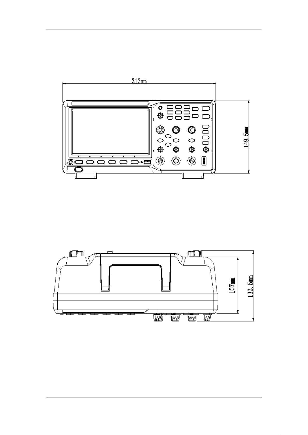
Appearance and Dimensions
SIGLENT
Figure 1 Front View (2-channel scope)
Figure 2 Top View (2-channel scope)
User Manual 3
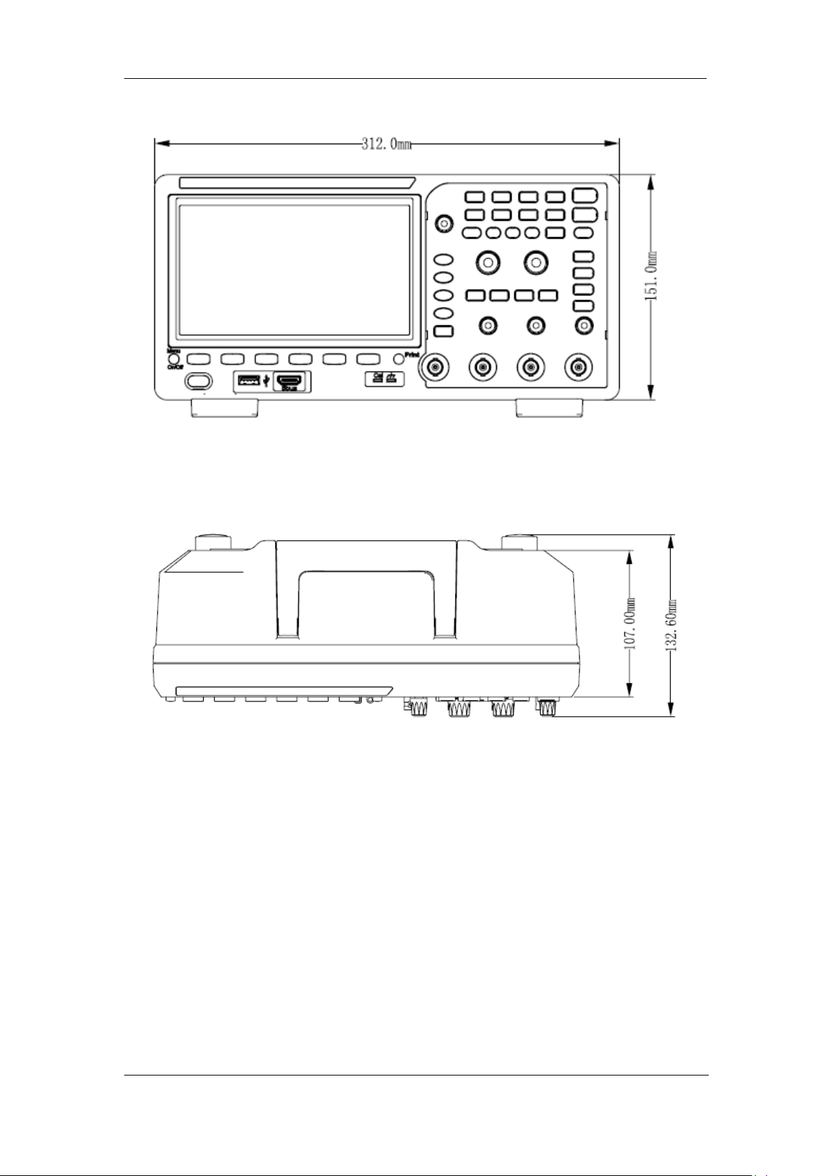
SIGLENT
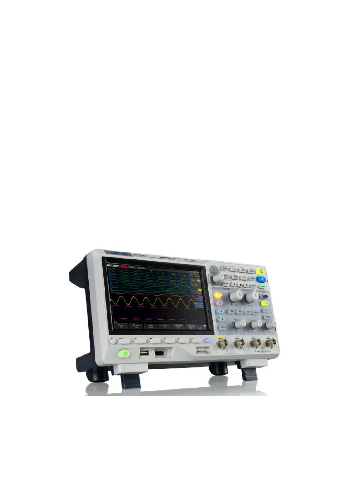
Figure 3 Front View (4-channel scope)
4 User Manual
Figure 4 Top View (4-channel scope)
SIGLENT
To Prepare the Oscilloscope for Use
To Adjust the Supporting Legs
Adjust the supporting legs properly to use them as stands to tilt the oscilloscope upwards
for stable placement of the oscilloscope as well as better operation and observation.
Figure 5 Adjust the Supporting Legs
User Manual 5
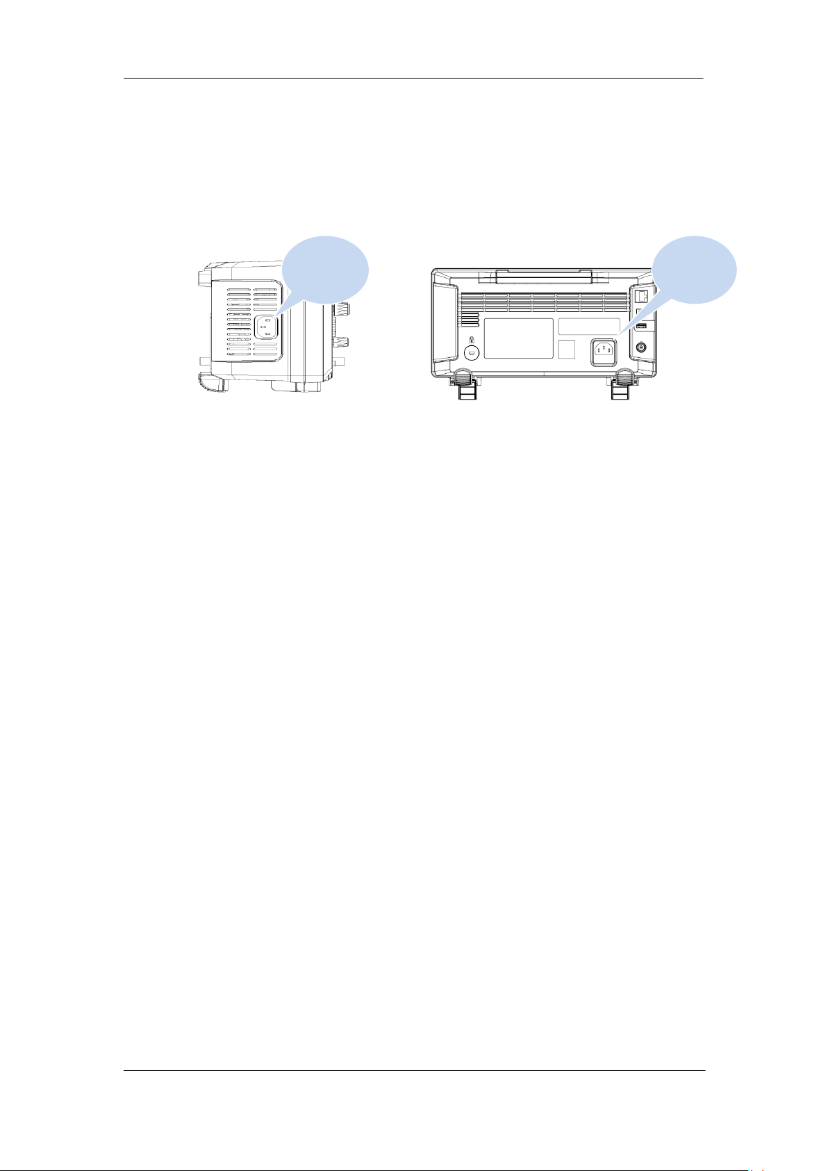
SIGLENT
Power
socket
Power
socket
To Connect to Power Supply
The power requirements of the oscilloscope are 100-240 V, 50/60Hz or 100-120 V, 400Hz.
Please use the power cord supplied with the accessories to connect the oscilloscope to
the power source.
2-channel scope 4-channel scope
Figure 6 To Connect to Power Supply
6 User Manual

SIGLENT
Power-on Inspection
When the oscilloscope is energized, press the power key at the lower-left corner of the
front panel to start the oscilloscope. During the start-up process, the oscilloscope
performs a series of self-tests and you can hear the sound of relay switching. After the
self-test is finished, the welcome screen is displayed.
To Connect the Probe
SIGLENT provides passive probes for the oscilloscopes. For detailed technical
information of the probes, please refer to the corresponding Probe User’s Guide.
Connect the Probe:
1. Connect the BNC terminal of the probe to a channel BNC connector of the
oscilloscope at the front panel.
2. Connect the probe tip to the circuit point to be tested and connect the ground alligator
clip of the probe to the circuit ground terminal.
User Manual 7
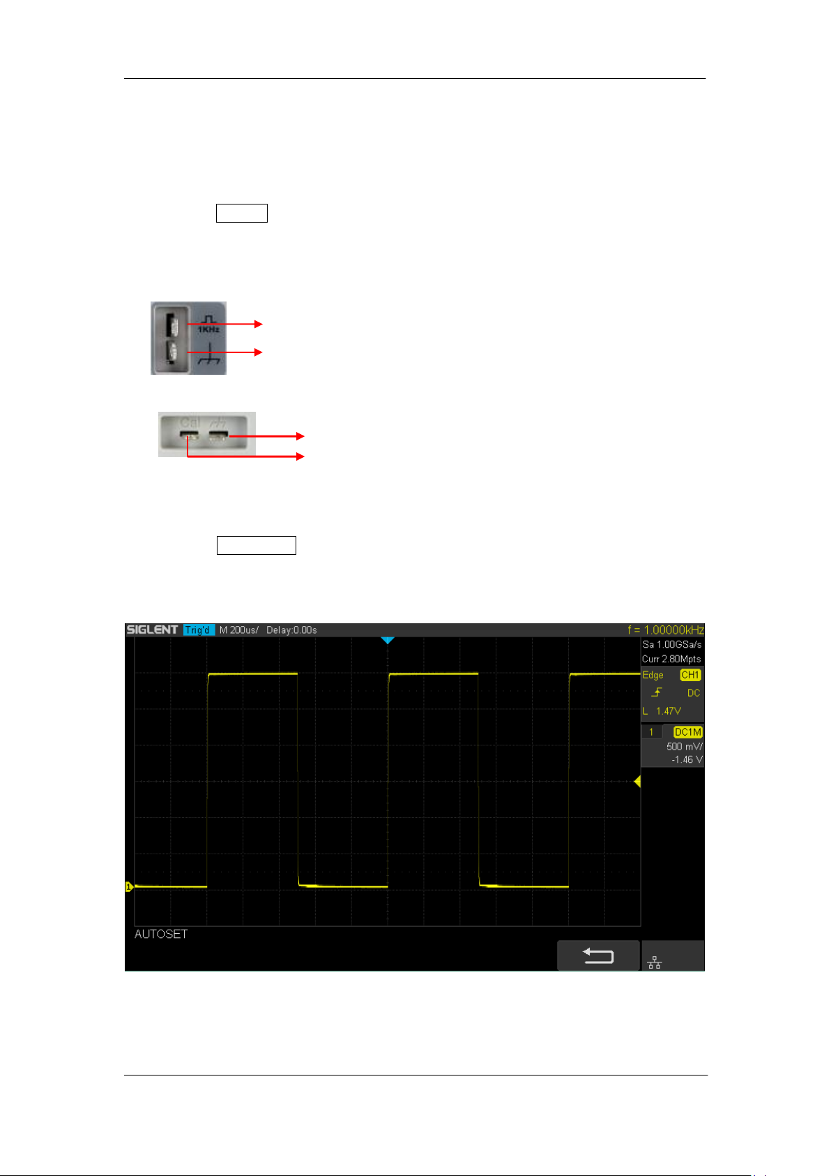
SIGLENT
Ground Terminal
Compensation Signal Output Terminal
Function Inspection
1. Press the Default button on the front panel to restore the instrument to its default
configuration.
2. Connect the ground alligator clip of the probe to the “Ground Terminal” under the
probe compensation signal output terminal.
Compensation Signal Output Terminal
Ground Terminal
2-channel scope
4-channel scope
3. Use the probe to connect the input terminal of CH1 of the oscilloscope and the
“Compensation Signal Output Terminal” of the probe.
4. Press the Auto Setup.
5. Observe the waveform on the display. In normal condition, the display should be a
square waveform as shown in the figure below:
6. Use the same method to test the other channels. If the square waveforms actually
shown do not match that in the figure above, please perform “Probe Compensation”
8 User Manual
Figure 7 Function Inspection

SIGLENT
in the next section.
WARNING
To avoid electric shock during the use of probe, please make sure that the
insulated wire of the probe is in good condition and do not touch the metallic
part of the probe when the probe is connected to high voltage source
Probe Compensation
When the probes are used for the first time, you should compensate the probes to match
the input channels of the oscilloscope. Non-compensated or poorly compensated probes
may cause measurement inaccuracy or error. The probe compensation procedures are as
follows.
1. Set the switch to 10X on the probe.
2. Perform steps 1, 2, 3 and 4 of “Function Inspection” in the previous section.
3. Check the waveforms displayed and compare them with the following:
Over Perfectly Under
Compensated Compensated Compensated
4. Use a nonmetallic driver to adjust the low-frequency compensation adjustment hole
on the probe until the waveform displayed is as the “Perfectly compensated” in the
figure above.
User Manual 9
SIGLENT
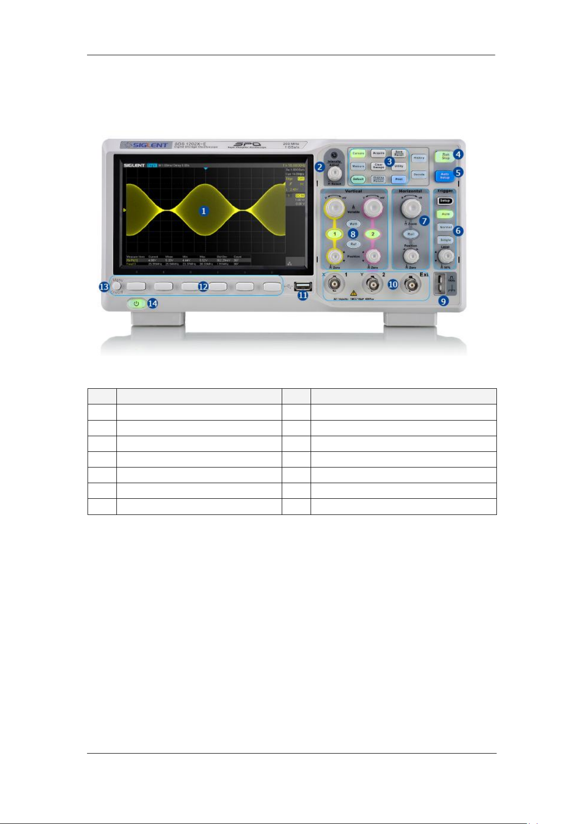
NO.
Description
NO.
Description
1
LCD Display
8
Vertical Control
2
Universal Knob
9
Probe Compensation/ Ground Terminal
3
Common Function Menus
10
Analog Channel and Ext Input
4
Run/Stop
11
USB Host
5
Auto Setup
12
Menu Softkey
6
Trigger Control
13
Menu on/off
7
Horizontal Control
14
Power Button
Front Panel Overview
Figure 8 2-channel Scope Front Panel Overview
10 User Manual
SIGLENT
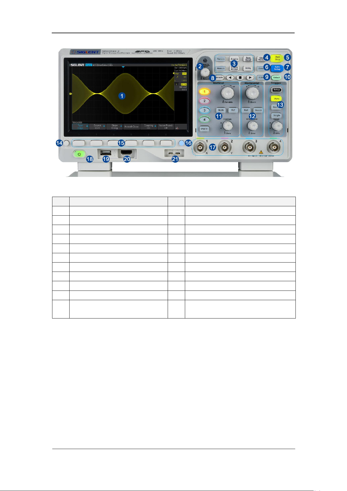
NO.
Description
NO.
Description
1
LCD Display
12
Horizontal Control
2
Universal Knob
13
Trigger Control
3
Common Function Menus
14
Menu on/off
4
Clear Sweeps
15
Menu Softkey
5
Run/Stop
16
One- Button shortcut for Save
6
Decode
17
Analog Channel
7
Auto Setup
18
Power Button
8
Navigate
19
USB Host
9
History
20
Digital Inputs
10
Default
21
Probe Compensation/ Ground Terminal
11
Vertical Control, Math, REF and
Digital
Figure 9 4-channel Scope Front Panel Overview
User Manual 11
 Loading...