

SIGLENT SDS1000CML+, SDS1000DL+ User Manual

User Manual
SDS1000CML+/SDS1000DL+
Digital Oscilloscope
UM0101A-E01A
SIGLENT TECHNOLOGIES CO,.LTD


SIGLENT
SDS1000CML+/SDS1000DL+ User Manual I
Declaration
Copyright © by SIGLENT TECHNOLOGIES CO,.LTD. All rights reserved.
Contents in this Manual are not allowed to copy, extract and translate
before being allowed by SIGLENT.

SIGLENT
II SDS1000CML+/SDS1000DL+ User Manual
Brief Introduction
Characteristic:
● The volume of the oscilloscope is cabinet and it is portable
● 7” Color TFT LCD display
● 2 channels, Bandwidth: 40MHz-150 MHz
● Single real-time sampling rate is: 1Gsa/s;
Equivalent sampling rate is 50GSa/s.
● Trigger types: Edge, Pulse, Video,Slope and Alternative
● Unique Digital Filter function and Waveform recorder function
● Auto measure thirty two parameters and support all measurement
function.
●Two groups’ reference waveforms and twenty groups’ capture
waveforms and twenty groups’ setups internal save/recall function
and USB flash drive save/recall function.
● Cursor types: Manual mode, Track mode and Auto mode.
● Channel waveform and its FFT waveform display on split screen.
● Waveform Intensity and Grid Brightness can be adjusted.
● Menu display in the form of pop-up that in order to convenience users to
use it.
● Rich Screen display styles: Classical, Modern, Tradition, Succinct.
● Multiple Language User Interface.
● Support Multilingual online help system
●Standard interface: USB Host, USB Device, LAN port
Standard Accessories:
● 1:1/10:1 probe (2 PCS)
● Power Cable that fits the standard of destination country
● Qualified Certification.
● CD (including EasyScopeX computer software system)
● Quick Start
● USB Cable

SIGLENT
SDS1000CML+/SDS1000DL+ User Manual III
General Safety Summary
Carefully read the following safety precautions to avoid person injury and prevent
damage to the instrument and any products connected to it. To avoid potential
hazards, please use the instrument as specified.
Only qualified technician should perform service procedures
To Avoid Fire or Personal Injure
Use Proper Power Line
Use only the special power line of the instrument which approved by local state.
Ground the Instrument
The instrument grounds through the protective terra conductor of the power line.
To avoid electric shock, the ground conductor must be connected to the earth.
Make sure the instrument is grounded correctly before connect its input or output
terminals.
Connect the Signal Wire Correctly
The potential of the signal wire is equal to the earth, so do not connect the signal
wire to a high voltage. Do not touch the exposed contacts or components.
Look Over All Terminals’ Ratings
To avoid fire or electric shock, please look over all ratings and sign instruction of
the instrument. Before connecting the instrument, please read the manual
carefully to gain more information about the ratings.
Not Operate with Suspected Failures
If you suspect that there is a damage of the instrument, please let a qualified
service personnel check it.
Avoid Circuit or Wire Exposed Components Exposed
Do not touch exposed contacts or components when the power is on.
Do not operate in wet/damp conditions.
Do not operate in an explosive atmosphere.
Keep the surface of the instrument clean and dry.

SIGLENT
IV SDS1000CML+/SDS1000DL+ User Manual
If the equipment is used in a manner not specified by the manufacturer, the
protection provided by the equipment may be impaired.
This product has been tested to the requirements of CAN/CSA-C22.2 No.
61010-1, second edition, including Amendment 1, or a later version of the
same standard incorporating the same level of testing requirements.
Not to use the product for measurements within other measurement
categories, such as CAT II, CAT III, CAT IV.
Not to use the equipment for measurements on mains circuits, not to use
the equipment for measurements on voltage exceed the voltage range
describe in the manual.
Only probe assemblies which meet the manufacturer’s specifications shall
be used.
The Responsible body or operator should refer to the instruction manual to
preserve the protection afford by the equipment. If the equipment is used in
a manner not specified by the manufacturer, the protection provided by the
equipment may be impaired.
Any parts of the device and its accessories are not allowed to be changed or
replaced, other than authorized by the manufacturer of his agent.
SIGLENT
SDS1000CML+/SDS1000DL+ User Manual V
Safety Terms and Symbols
Terms used on the instrument. Terms may appear on the instrument:
DANGER: Indicates an injury or hazard that may be immediately happen.
WARNING: Indicates an injury or hazard that may be not immediately
happen.
CAUTION: Indicates that a potential damage to the instrument or other
property might occur.
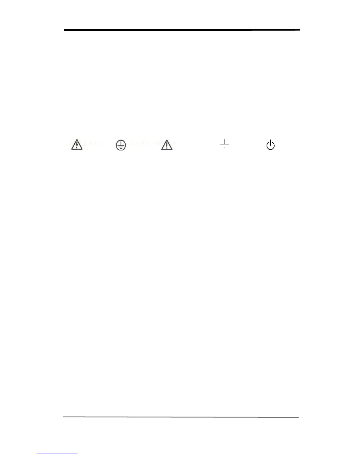
Symbols used on the instrument. Symbols may appear on the instrument:
Hazardous Protective Warning Earth Ground Power
Voltage Earth Ground Switch

SIGLENT
VI SDS1000CML+/SDS1000DL+ User Manual
Content
Brief Introduction ....................................................................................................II
Chapter 1 Accidence ..............................................................................................1
1.1 Accidence of Panel and Display Information ........................................................... 2
1.2 Function Checking ................................................................................................... 5
1.3 Probe .................................................................................................................. 7
1.3.1 Probe Safety ................................................................................................. 7
1.3.2 Probe Attenuation Setting .......................................................................... 7
1.3.3 Probe Compensation .................................................................................. 8
Chapter 2 Functions Instruction and Operation .....................................................9
2.1 Menu and Control Button ....................................................................................... 10
2.2 Connector ............................................................................................................... 12
2.3 Auto Setup .............................................................................................................. 13
2.4 Default Setup .......................................................................................................... 14
2.5 Universal Knob ...................................................................................................... 15
2.6 Vertical System ....................................................................................................... 15
2.6.1 CH1, CH2 Channel .................................................................................... 16
2.6.2 Using Vertical “Position” Knob and “Volt/div” Knob .............................. 21
2.6.3 Math Functions........................................................................................... 21
2.6.4 Using Ref .................................................................................................... 27
2.7 Horizontal System .................................................................................................. 29
2.7.1 Horizontal Control Knob............................................................................ 30
2.7.2 Window Zone ............................................................................................. 30
2.8 Trigger System ....................................................................................................... 32
2.8.1 Signal Source ............................................................................................. 33
2.8.2 Trigger Type ................................................................................................ 34
2.8.3 Coupling ...................................................................................................... 47
2.8.4 Position........................................................................................................ 47
2.8.5 Slope & Level ............................................................................................. 48
2.8.6 Trigger Holdoff ........................................................................................ 49
2.9 Acquiring Signals System ...................................................................................... 50
2.10 Display System ..................................................................................................... 56
2.10.1 X-Y Format ............................................................................................... 59
2.11 Measure System ................................................................................................... 60
2.11.1 Scale Measurement ................................................................................ 60
2.11.2 Cursor Measurement .............................................................................. 60
2.11.3 Auto Measurement .................................................................................. 66
2.12 Storage System ..................................................................................................... 72
2.13 Utility System ....................................................................................................... 85
2.13.1 System Status .......................................................................................... 88
2.13.2 Language .................................................................................................. 88
2.13.3 Self Calibration......................................................................................... 89
2.13.4 Self Test ....................................................................................................... 90
2.13.5 Updating the System Software .............................................................. 92
2.13.6 Pass/Fail ................................................................................................... 92
2.13.7 Waveform Record.................................................................................... 96
2.13.8 Recorder ................................................................................................... 99
2.13.9 Remote Control ...................................................................................... 102
2.14 Online Help Function ......................................................................................... 107
Chapter 3 Prompting Messages and Troubleshooting ...................................... 108

SIGLENT
SDS1000CML+/SDS1000DL+ User Manual VII
3.1 Prompting Messages: ........................................................................................... 108
3.2 Troubleshooting .................................................................................................... 110
Chapter 4 Service and Support .......................................................................... 112
4.1 Maintain Summary ............................................................................................... 112
4.2 Contact SIGLENT ................................................................................................ 113
Appendix A: Default Setup ................................................................................. 114
Appendix B: Daily Maintain and Cleaning .......................................................... 116


SIGLENT
SDS1000CML+/SDS1000DL+ User Manual 1
Chapter 1 Accidence
SDS1000CML+ /SDS1000DL+ Series Digital Oscilloscope is mini-type and
portable bench type instruments, which could be used for measuring as the GND
voltage.
This Chapter shows you how to operate following tasks:
◆ Accidence of panel and Display information
◆ Simple checking of functions
◆ Matching probes attenuation coefficient
◆ Probe compensation
SIGLENT
2 SDS1000CML+/SDS1000DL+ User Manual
1.1 Accidence of Panel and Display Information
1.1.1 Front Panel
It is important for you to understand the DSO’s front panel before operating it. The
following contents are the brief introduction for the front panel function, which is
useful to be familiar with the operation of the SDS1000CML+/SDS1000DL+
Series Digital Storage Oscilloscope in short time.
The oscilloscopes provides an easy-to-use front panel to convenience users to
operate them, the panel contains knobs and buttons. There is a list of five ashen
buttons as menu operational buttons on the right of display screen. You can set
different options of the current menu in virtue of them. Other buttons are function
buttons; you can enter different function menus or obtain given function
application in virtue of them.
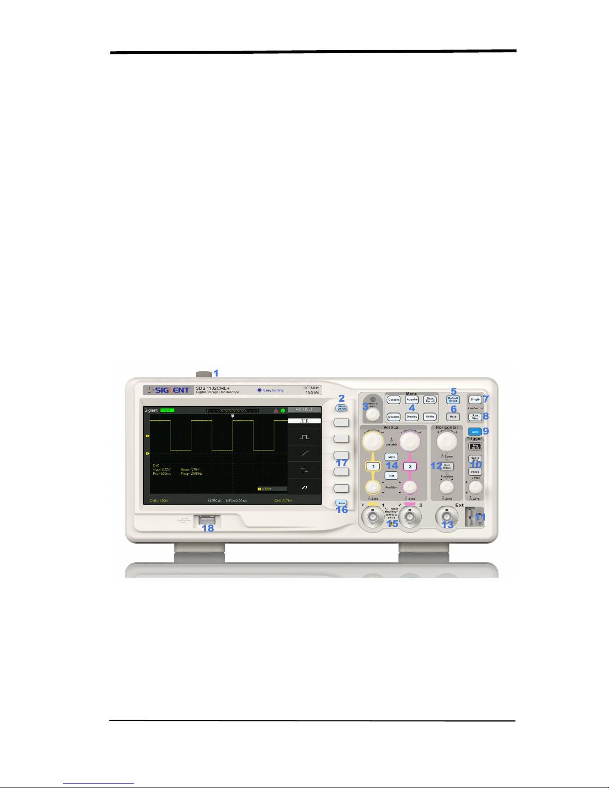
Picture 1.1-1 SDS1000CML+ Series Front Panel
SIGLENT
SDS1000CML+/SDS1000DL+ User Manual 3
No. Description No. Description
1
Power button 10 Trigger Control Area
2
Menu On/Off 11 Probe Compensation
3
Universal Knob 12 Horizontal Control Area
4
Functions Menus 13 Ext Trigger Terminal
5
Default Setup 14 Vertical Control Area
6
Help button 15 Channel Input Terminal
7
Single Trigger 16 Print key
8
Run/Stop Control 17 Menu Softkey
9
Auto Setup 18 USB Host
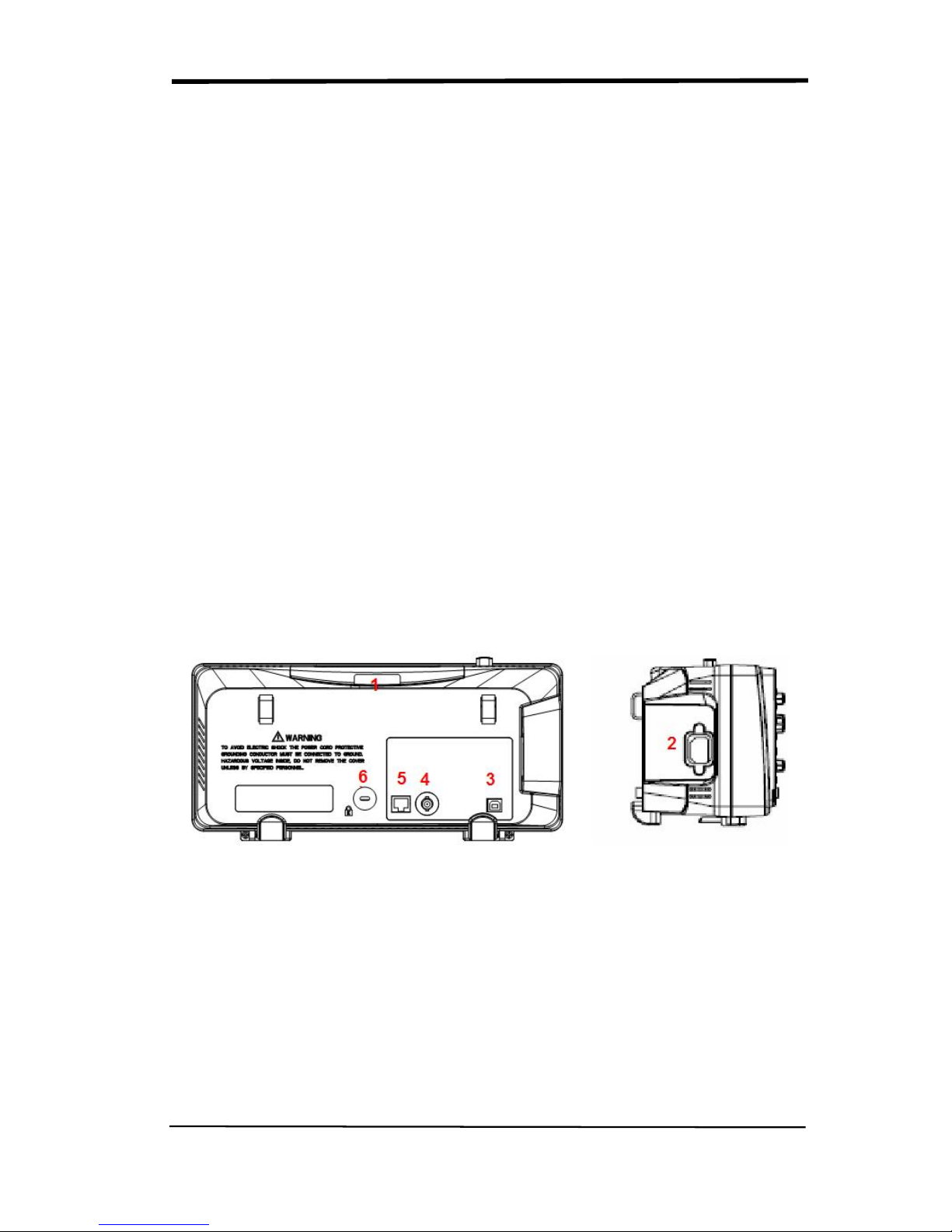
1.1.2 Back and Side Connections
The following images show back and side panel connection locations.
Picture 1.1-2 SDS1000CML+ Back and Side panel
1. Handle
2. AC Power Input Terminal
3. USB Device Connector
4. Pass/Fail Output Connector
5. LAN Port
6. Lock Hole
SIGLENT
4 SDS1000CML+/SDS1000DL+ User Manual
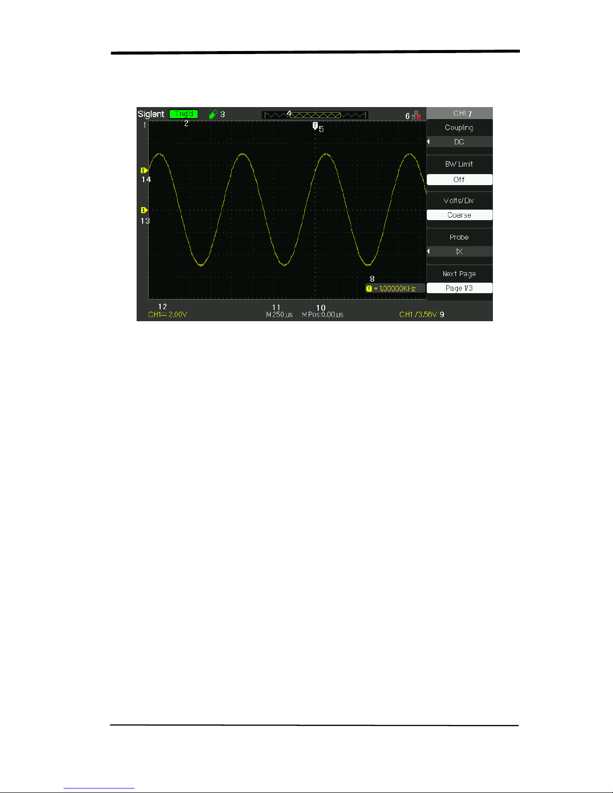
1.1.3 User display interface
Picture 1.1-3
1.Product Logo
Siglent is the registered trademark of our company.
2. Trigger status
Armed. The oscilloscope is acquiring pre-trigger data. All triggers are ignored
in this state.
Ready. All pre-trigger data has been acquired and the oscilloscope is ready to
accept a trigger.
Trig’d. The oscilloscope has seen a trigger and is acquiring the posttrigger data.
Stop. The oscilloscope has stopped acquiring waveform data.
Auto. The oscilloscope is in auto mode and is acquiring waveforms in the
absence of triggers.
Scan. The oscilloscope is acquiring and displaying waveform data continuously in
scan mode.
3. USB Host connected mark.
4. Waveform memory
Show the position of the current waveform in the memory of the
oscillsocpe.
5. Trigger position.
Turn the HORIZONTAL POSITION knob to adjust the trigger position of the

SIGLENT
SDS1000CML+/SDS1000DL+ User Manual 5
waveform.
6. Show the LAN port.
Indicates the LAN port is connected.
Indicates the LAN port is disconnected.
7. Show the Channel symbol.
8. Readout shows trigger signal frequency..
9. Readout shows the trigger level value and trigger type..
10.Readout shows the trigger delay of waveform.
11. Readout shows the main time base setting.
12. Icon shows the channel setting.
13. Icon shows the channel offset position.
14. Icon shows the trigger level position
1.2 Function Checking
When you check whether or not the oscilloscope could work smoothly, please
operate as following:
1. Power On the oscilloscope.
Press “DEFAULT SETUP” to show the result of the self check. The probe default
attenuation is 1X.
Picture 1.2- 1
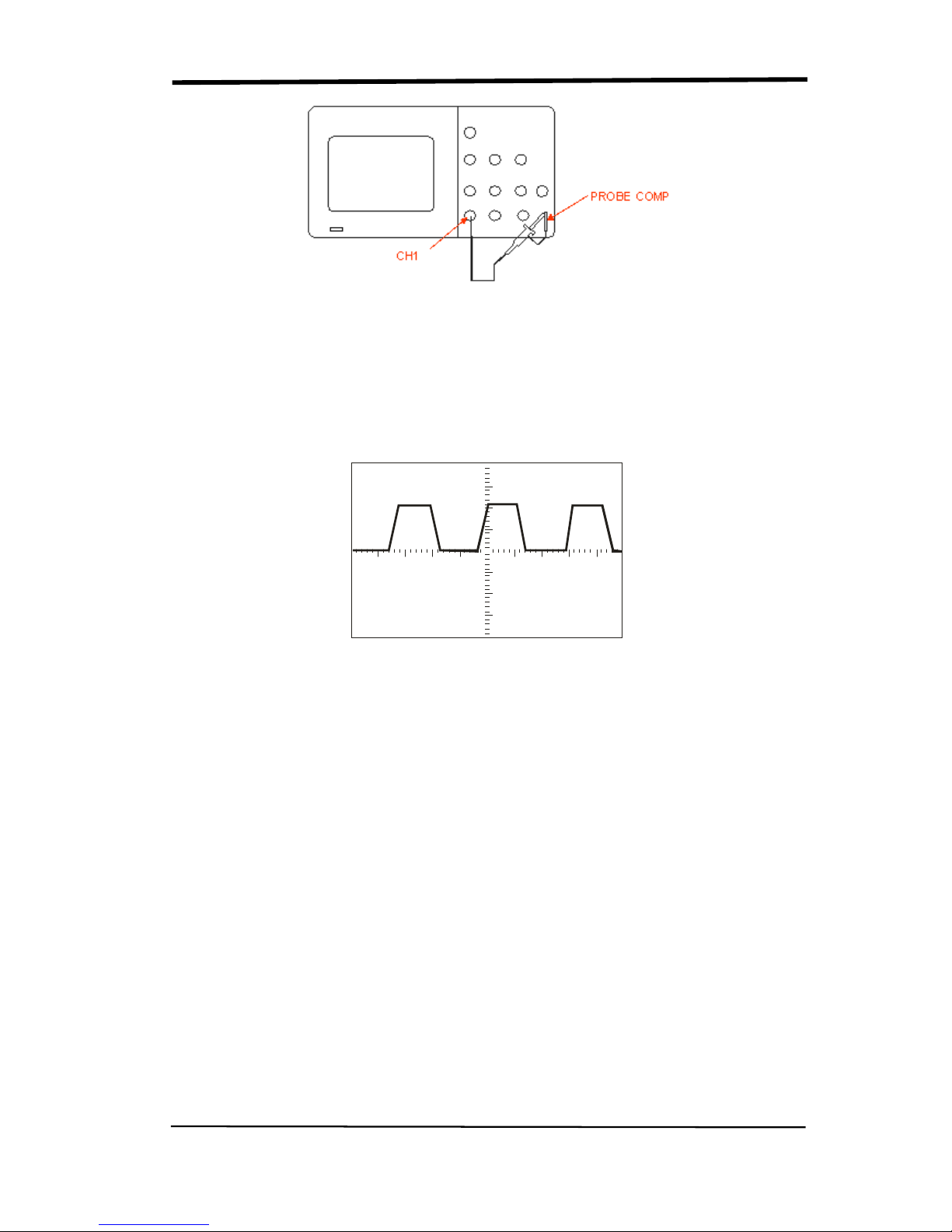
2. Set the switch to 1X on the probe and connect the probe to channel 1 on the
oscilloscope. To do this, align the slot in the probe connector with the key on the
CH 1 BNC, push to connect, and twist to the right to lock the probe in place.
Connect the probe tip and reference lead to the PROBE COMP connectors
SIGLENT
6 SDS1000CML+/SDS1000DL+ User Manual
Picture 1.2-2
3.Press “AUTO” to show the 1 KHz frequency and about 3V peak-peak square
wave in couple seconds
Picture 1.2-3
4. Press “CH1” two times to cancel the channel 1, Press“CH2” to change screen
into channel 2, reset the channel 2 as step 2 and step 3.
SIGLENT
SDS1000CML+/SDS1000DL+ User Manual 7
1.3 Probe
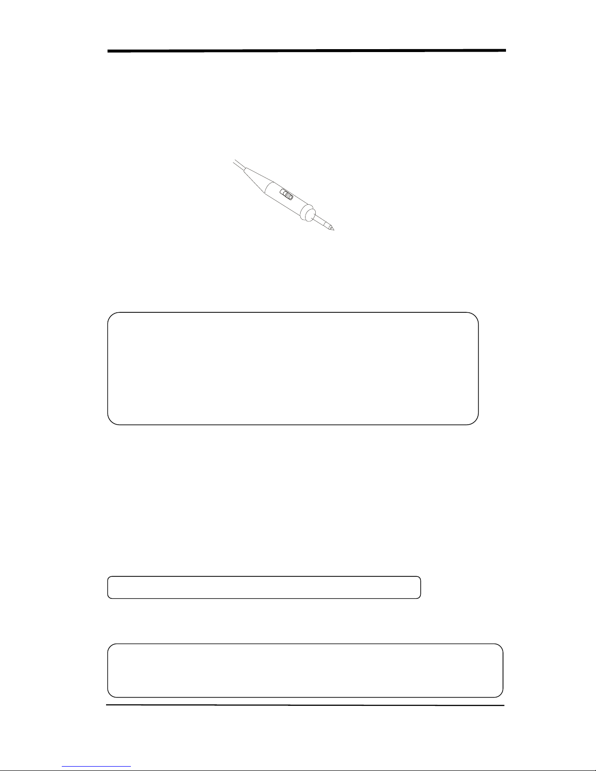
1.3.1 Probe Safety
A guard around the probe body provides a finger barrier for protection from
electric shock.
Picture 1.3-1
Connect the probe to the oscilloscope and connect the ground terminal to ground
before you take any measurements.
1.3.2 Probe Attenuation Setting
Probes are available with various attenuation factors which affect the vertical
scale of the signal. The Probe Check function verifies that the Probe attenuation
option matches the attenuation of the probe.
You can push a vertical menu button (such as the CH 1 MENU button), and select
the Probe option that matches the attenuation factor of your probe.
Be sure that the attenuation switch on the probe matches the Probe option in the
oscilloscope. Switch settings are 1X and 10X.
Note: ● To avoid electric shock when using the probe, keep fingers behind the
guard on the probe body.
● To avoid electric shock while using the probe, do not touch metallic
portions of the probe head while it is connected to a voltage source.
Connect the probe to the oscilloscope and connect the ground terminal
to ground before you take any measurements.
Note
:
The default setting for the Probe option is 1X.
Note:
When the attenuation switch is set to 1X, the probe
limits the bandwidth of the
oscilloscope to 6MHz (according to Probe spec). To use the full bandwidth of the
SIGLENT
8 SDS1000CML+/SDS1000DL+ User Manual
1.3.3 Probe Compensation
As an alternative method to Probe Check, you can manually perform this
adjustment to match your probe to the input channel.
Picture1.3-2
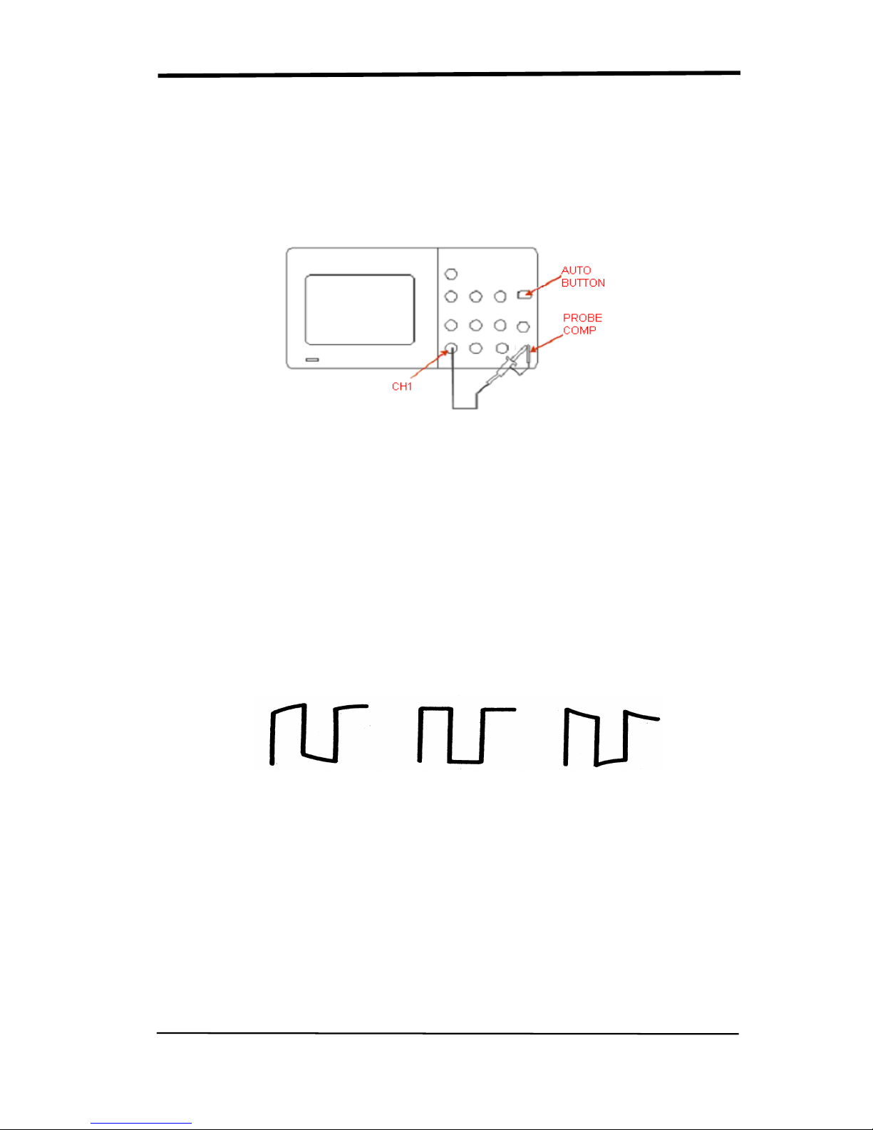
1. Set the Probe option attenuation in the channel menu to 10X. Set the switch to
10X on the probe and connect the probe to channel 1 on the oscilloscope. If you
use the probe hook-tip, ensure a proper connection by firmly inserting the tip
onto the probe.
2. Attach the probe tip to the PROBE COMP~3V connector and the reference
lead to the PROBE COMP Ground connector. Display the channel and then
push the “AUTO” button.
3. Check the shape of the displayed waveform.
Over Compensated under
Compensated correctly compensated
Picture 1.3-3
4. If necessary, adjust your probe. Repeat as necessary.

SIGLENT
SDS1000CML+/SDS1000DL+ User Manual 9
Chapter 2 Functions Instruction and Operation
To use your oscilloscope effectively, you need to learn about the following
oscilloscope functions:
◆ Menu and control button
◆ Connector
◆ Auto Setup
◆ Default Setup
◆ Universal knob
◆ Vertical System
◆ Horizontal System
◆ Trigger System
◆ Acquiring signals System
◆ Display System
◆ Measuring waveforms System
◆ Utility System
◆ Storage System
◆ Online Help function
SIGLENT
10 SDS1000CML+/SDS1000DL+ User Manual
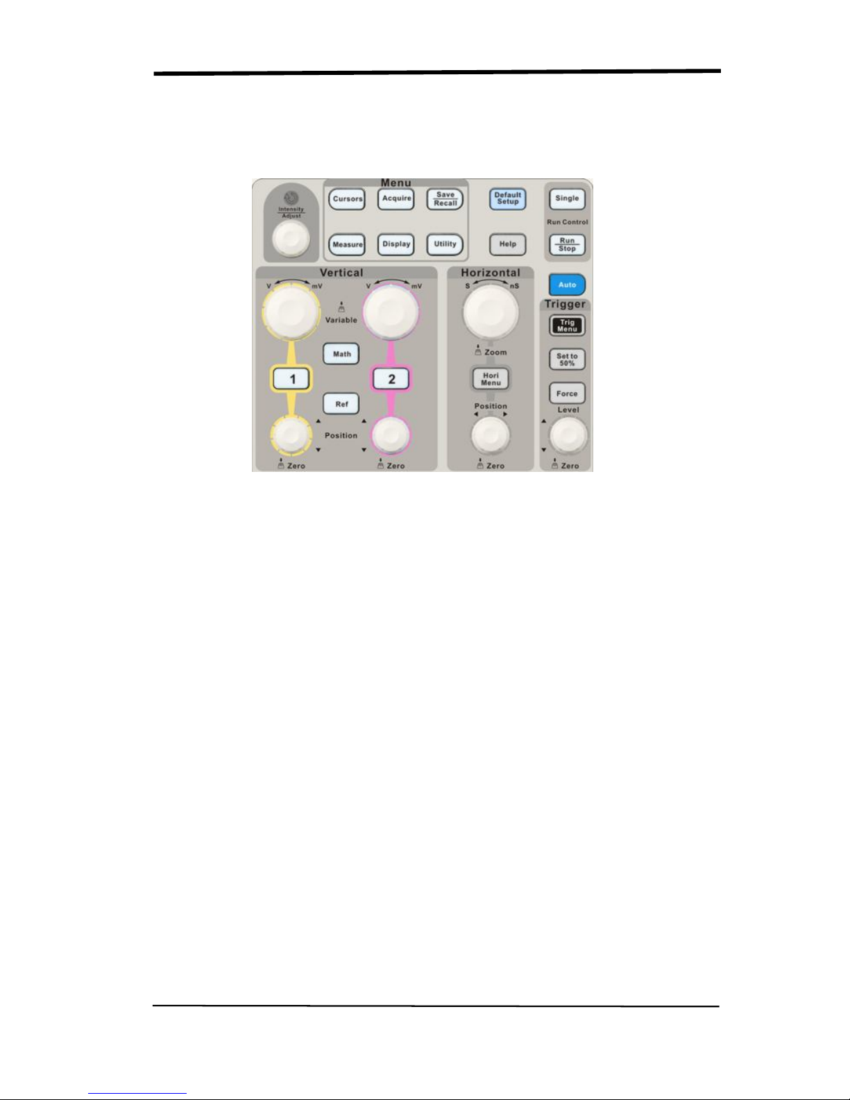
2.1 Menu and Control Button
Showing as the following picture:
Picture 2-1
■ Channel buttons (1, 2): Press a channel button to turn that channel ON or OFF
and open the channel menu for that channel. You can use the channel menu to
set up a channel. When the channel is on, the channel button is lit.
■ MATH: Press to display the Math menu. You can use the MAH menu to use the
oscilloscopes Math functions.
■ REF: Press to display the Ref Wave menu. You can use this menu to save and
recall four or two reference waveforms internal memory.
■ HORI MENU: Press to display the Horizontal menu. You can use the Horizontal
menu to display the waveform and zoom in a segment of a waveform.
■ TRIG MENU: Press to display the Trigger menu. You can use the Trigger menu
to set the trigger type (Edge. Pulse, Video, Slope, Alternative) and trigger
settings.
■ SET TO 50%: Press to stabilize a waveform quickly. The oscilloscope can
set the trigger level to be halfway between the minimum and maximum
voltage level automatically. This is useful when you connect a signal to the
EXT TRIG connector and set the trigger source to Ext or Ext/5.

SIGLENT
SDS1000CML+/SDS1000DL+ User Manual 11
■ FORCE: Use the FORCE button to complete the current waveform acquisition
whether the oscilloscope detects a trigger or not. This is useful for Single
acquisitions and Normal trigger mode.
■ SAVE/RECALL: Press to display the Save/Recall menu. You can use the
Save/Recall menu to save and recall up to 20 oscilloscope setups or waveforms
in internal memory (up to 20 waveforms) or on a USB memory device (limited by
memory capacity of USB device). You can also use it to recall the default factory
settings, to save waveform data as a comma-delimited file (.CSV), and to save
or print the displayed waveform image.
■ ACQUIRE: Press to display Acquire menu. You can use the Acquire menu to
set the acquisition Sampling Mode (Sampling, Peak Detect, Average).
■ MEASURE: Press to display a menu of measurement parameters.
■ CURSORS: Display the Cursor Menu. Vertical Position controls adjust cursor
position while displaying the Cursor Menu and the cursors are activated.
Cursors remain displayed (unless the “Type” option is set to “Off”) after leaving
the Cursor Menu but are not adjustable.
■ DISPLAY: Press to open the Display menu. You can use the Display menu to
set grid and waveform display styles, and persistence.
■ UTILITY: Press to open the Utlity menu. You can use the Utility menu to
configure oscilloscope features, such as sound, language, counter, etc. You can
also view system status and update software.
■ DEFAULT SETUP: Press to reset the oscilloscope’s settings to the default
factory configuration.
■ HELP: Enter the online help system.
■ AUTO: Automatically sets the oscilloscope controls to produce a usable display
of the input signals.
■ RUN/STOP: Continuously acquires waveforms or stops the acquisition.
Note:If waveform acquisition is stopped (using the RUN/STOP or SINGLE
button), the SEC/DIV control expands or compresses the waveform.
■ SINGLE: Acquire a single waveform and then stops.
SIGLENT
12 SDS1000CML+/SDS1000DL+ User Manual
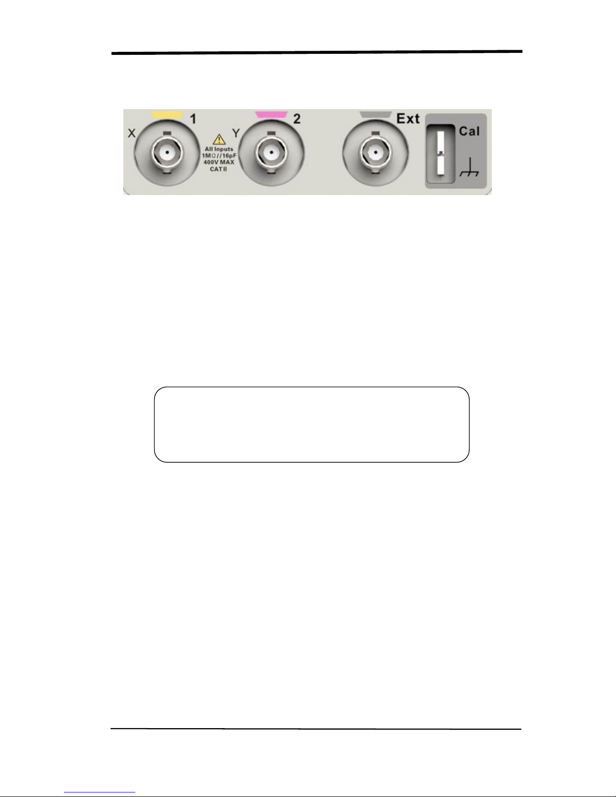
2.2 Connector
Picture 2-2
■ Channel Connector (CH1, CH2): Input connectors for waveforms display.
■ EXT TRIG: Input connector for an external trigger source. Use the Trigger
Menu to select the “Ext” or “Ext/5” trigger source.
■ Probe Component: Voltage probe compensation output and ground. Use
to electrically match the probe to the oscilloscope input circuit.
Note:If you connect a voltage source to a ground terminal, you
may damage the oscilloscope or the circuit under test. To avoid
this, do not connect a voltage source to any ground terminals.
SIGLENT
SDS1000CML+/SDS1000DL+ User Manual 13
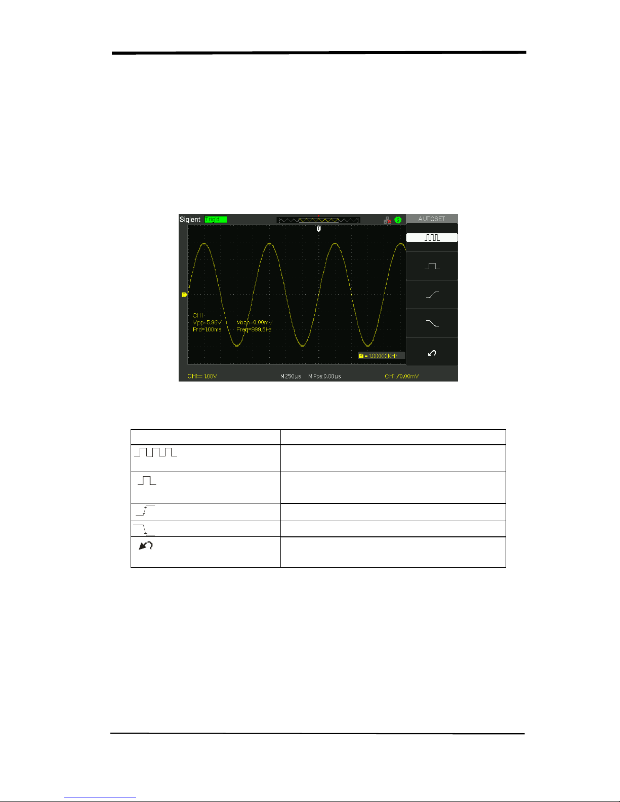
2.3 Auto Setup
The SDS1000CML+/SDS1000DL+ Series Digital Storage Oscilloscopes have a
Auto Setup function that identifies the waveform types and automatically adjusts
controls to produce a usable display of the input signal.
Press the AUTO button, and then press the menu option button adjacent to the
desired waveform as follows:
Picture 2-3
Table 2-1 Auto Set function Menu:
Option Description
(Multi-cycle sine)
Auto set the screen and display several
cyc signal.
(Single-cycle sine)
Set the screen and auto display single cyc
signal.
(Rising edge)
Auto set and show the rising time.
(Falling edge)
Auto set and show the falling time.
(Undo Setup)
Causes the oscilloscope to recall the
previous setup.
Auto set determines the trigger source based on the following conditions:
● If multiple channels have signals, channel with the lowest frequency signal.
● No signals found, the lowest-numbered channel displayed when Auto set was
invoked
● No signals found and no channels displayed, oscilloscope displays and uses
channel 1.

SIGLENT
14 SDS1000CML+/SDS1000DL+ User Manual
Table 2-2 Auto set the function item
Function
Setting
Acquire Mode Adjusted to Sampling
Display Format Y-T
Display Type Set to Dots for a video signal, set to Vectors
for an FFT spectrum; otherwise, unchanged
Vertical Coupling Adjusted to DC or AC according to the input
signal
Bandwidth Limit Off(full)
V/div Adjusted
VOLTS/DIV adjustability Coarse
Signal inverted Off
Horizontal position Center
S/div Adjusted
Trigger type Edge
Trigger source Auto detect the channel which has the input
signal
Trigger slope Rising
Trigger mode Auto
Trigger coupling DC
Trigger holdoff Minimum
Trigger level Set to 50%
2.4 Default Setup
The oscilloscope is set up for normal operation when it is shipped from the factory.
This is the default setup. To recall this setup, press the DEFAULT SETUP button.
The options, buttons and controls that change settings when you press the
DEFAULT SETUP button, refer to appendix B.
The DEFAULT SETUP button does not reset the following settings:
● Language option
● Saved reference waveform files
● Saved setup files
● Display contrast
● Calibration data
SIGLENT
SDS1000CML+/SDS1000DL+ User Manual 15
2.5 Universal Knob
Picture 2-5 Universal Knob
You can use the Universal knob with many functions, such as adjusting the
holdoff time, moving cursors, setting the pulse width, Setting the Video Linage,
adjusting the upper and lower frequency limit, adjust X and Y masks when
using the pass/fail function etc. You can also turn the “Universal” knob to
adjust the storage position of setups, waveforms, pictures when
saving/recalling and to select menu options.
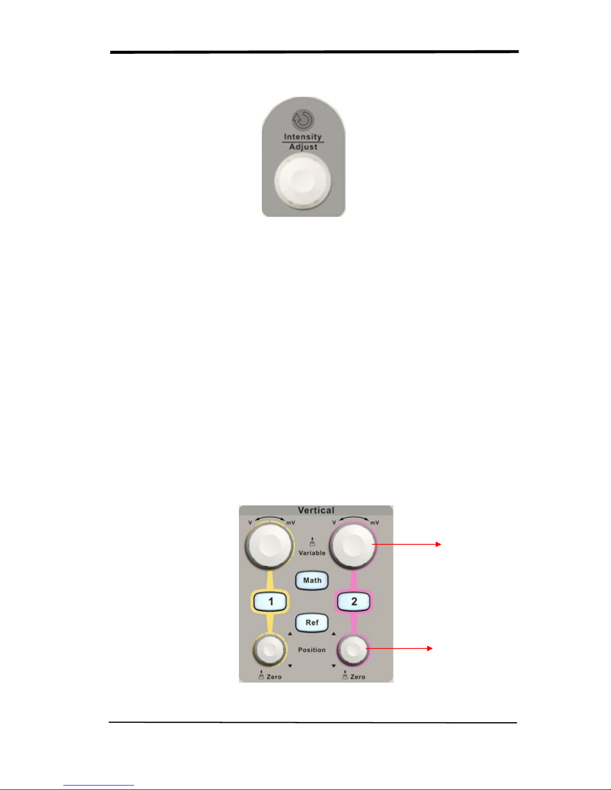
2.6 Vertical System
The vertical control could be used for displaying waveform, rectify scale and
position.
Picture 2.6-1
Volt/div Knob
Vertical Position
Knob
SIGLENT
16 SDS1000CML+/SDS1000DL+ User Manual
2.6.1 CH1, CH2 Channel
Table 2-1 CH1, CH2 function menu 1:
Option
Setting
Introduction
Coupling
DC
AC
GND
DC passes both AC and DC components of
the input signal.
AC blocks the DC component of the input
signal and attenuates signals below 10 Hz.
GND disconnects the input signal.
BW limit
On
Off
Limits the bandwidth to reduce display
noise; filters the signal to reduce noise and
other unwanted high frequency
components.
Volts/Div
Coarse
Fine
Selects the resolution of the Volts/Div knob
Coarse defines a 1-2-5 sequence.
Fine changes the resolution to small steps
between the coarse settings.
Probe
1X,5X
10X,50X
100X,
500X,1000X
Set to match the type of probe you are
using to ensure correct vertical readouts.
Next Page Page 1/3 Enter the second page of the menu.
Table 2-4 CH1, CH2 function menu 2:
Option
Setting
Instruction
Invert
on
off
Turn on invert function.
Turn off invert function.
Digital Filter
Press this button to enter the “Digital Filter
menu”.(See table 2-5)
Next Page Page 2/3 Enter the second page of the menu.
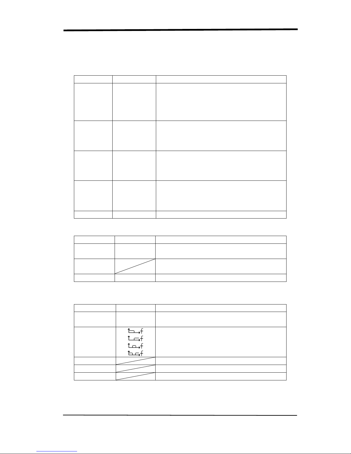
Table 2-5 Digital Filter function menu:
Option
Setting
Introduction
Digital Filter
On
Off
Turn on the digital filter.
Turn off the digital filter.
Type
Setup as LPF (Low Pass Filter).
Setup as HPF (High Pass Filter).
Setup as BPF (Band Pass Filter).
Setup as BRF (Band Reject Filter).
Upper_limit Turn the “Universal” knob to set upper limit.
Lower_limit Turn the “Universal” knob to set lower limit.
Return Return the digital filter main menu.
SIGLENT
SDS1000CML+/SDS1000DL+ User Manual 17
Setting CH1, CH2 Channels
Each channel has its own separate Menu. The items are set up separately
according to each channel.
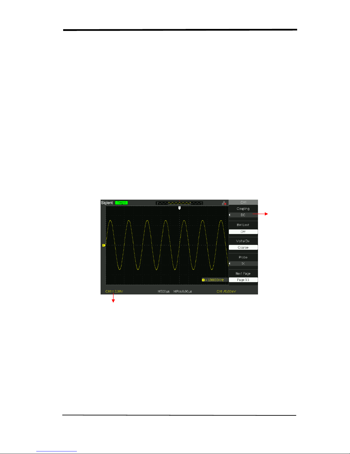
1. Choosing Coupling
Take the CH1 for example; the tested signal is a sine wave signal with DC
deflection:
● Press“CH1”→“Coupling”→“AC”, Set to AC couple mode. It blocks the DC
component of the input signal.
● Press“CH1”→“Coupling”→“DC”, Set to DC couple mode. Both DC and
AC component could be obstructed.
● Press“CH1”→“Coupling”→“GND”, Set to GROUND mode. It disconnects the
input signal.
Picture 2.6-2
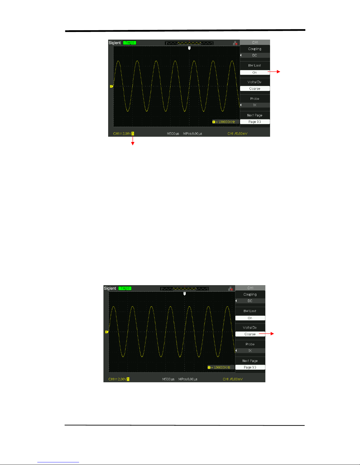
2. Bandwidth Limiting
Take the CH1 for example; the tested signal is a pulse signal with the high
frequency surge:
● Press “CH1”→“BW Limit”→ “On”,Set the band width Limited to open state. The
high frequency component which is higher than 20MHz obstructed.
● Press“CH1”→“BW Limit”→ “Off”, Set bandwidth Limited to close state, the High
Frequency component in the tested signal could pass.
Set to DC
Coupling
DC Status
SIGLENT
18 SDS1000CML+/SDS1000DL+ User Manual
Picture 2.6-3
3. Adjust Sensitivity
Vertical scale adjusting has Coarse and Fine two modes, Vertical sensitivity range
is 2mV/div~10V/div scale.
Take the CH1 for example:
● Press “CH1”→“Volts/Div”→“Coarse”. It is the default setting of Volts/Div, and it
makes the vertical scaling in a 1-2-5-step sequence from 2mv/div, 5mv/div,
10mv/div to 10v/div.
● Press “CH1”→“Volts/Div”→“Fine”. This setting changes the vertical to small
steps between the coarse settings. It will be helpful when you need to adjust the
waveform vertical size in smooth steps.
Picture 2.6-4
Set BW
to 20MHz
BW Limit Symbol
Set to
Coarse
SIGLENT
SDS1000CML+/SDS1000DL+ User Manual 19
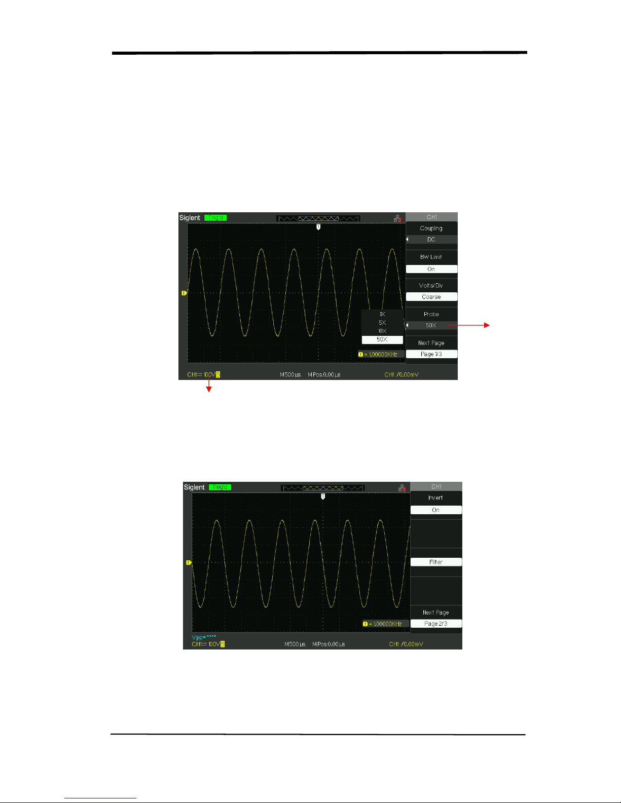
4. Setting Probe Attenuation
In order to assort the attenuation coefficient, you need to response in the channel
operation Menu. If the attenuation coefficient is 10:1, the input coefficient should
be set to 10X, so that the mistake of the Volts/div information and measure testing
should be forbidden.
Take the CH1 for example, when you use the 100:1 probe:
● Press“CH1”→“Probe” →“100”
Picture 2.6-5
5. Inverting waveforms
Take the CH1 for example:
● Press“CH1”→Next Page“ page1/3” →“Invert”→“On”:
Picture 2.6-6
Probe
Attenuation
Factor
Status of 50X
SIGLENT
20 SDS1000CML+/SDS1000DL+ User Manual
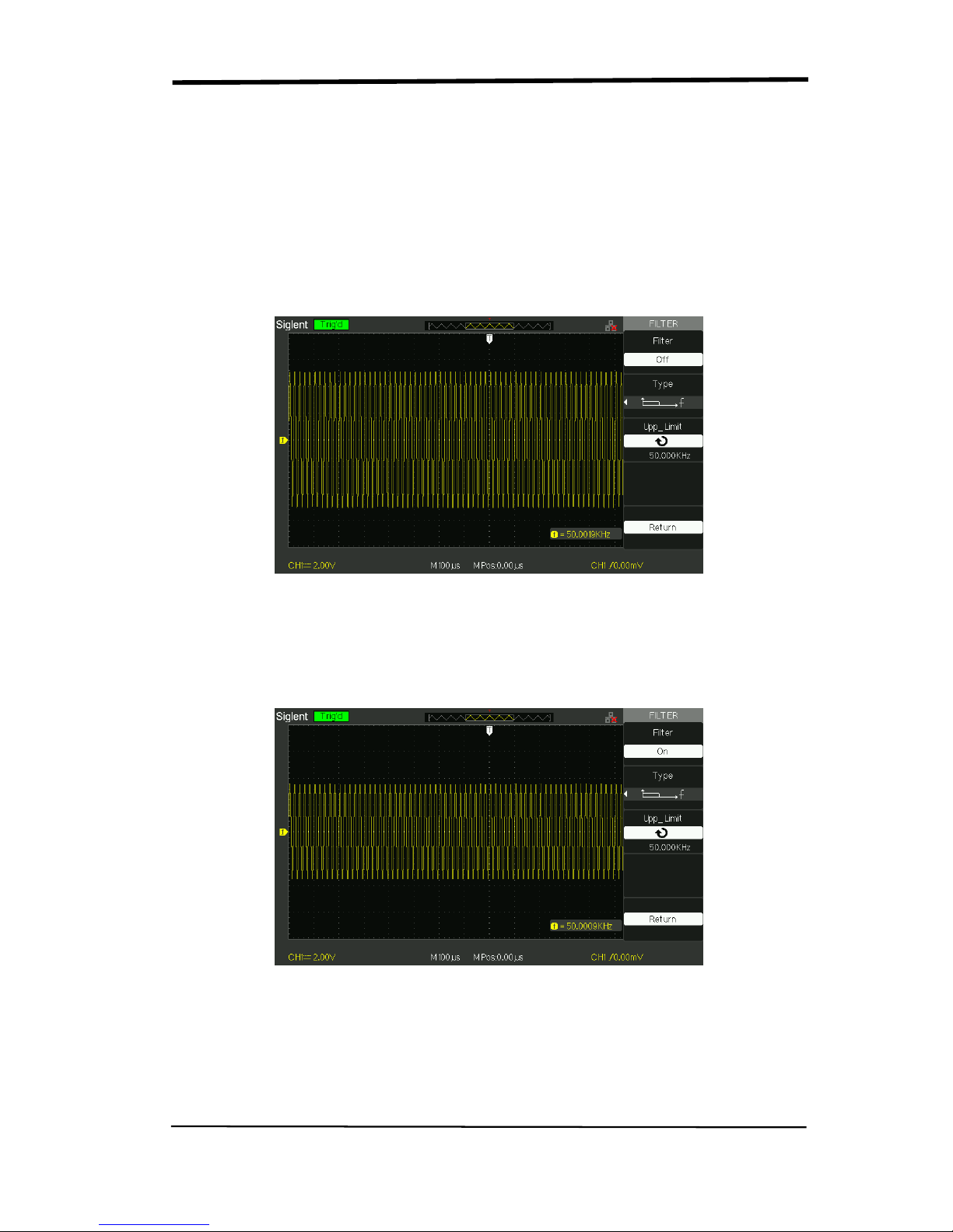
6. Using the Digital Filter
Press “CH1”→“Next Page page1/3”→ “Filter”, display the digital filter menu. Select
“Filter Type”, then select “Upper Limit” or “Lower Limit” and turn the “Universal”
knob to adjust them.
● Press “CH1”→“Next Page page1/3”→ “Filter” →“Off”. Turn off the Digital Filter
function.
Picture 2.6-7
● Press “CH1”→ “Next Page page1/3”→ “Filter” → “On”. Turn on the Digital
Filter function.
Picture 2.6-8
 Loading...