

SIGLENT SDS1000D Service Manual

Service Manual
Service Manual
SDS1000D Digital Storage Oscilloscope
June 2011
SIGLENT Technologies Co., Ltd.

Service Manual
Declaration
Copyright © SIGLENT Technologies Co.,Ltd. All rights reserved.
Contents in this Manual are not allowed to copy, extract and translate before being
allowed by SIGLENT Company.

Service Manual
General Safety Summary
Review the following safety precautions to avoid injury and prevent damage to this product or
any products connected to it. To avoid potential hazards, use this product only as specified.
Only qualified personnel should perform service procedures.
1. To Avoid Fire or Personal Injury
●
●●
● Use Proper Power Cord. Use only the power cord specified for this product and certified
for the country of use.
●
●●
● Connect and Disconnect Properly. Do not connect or disconnect probes or test leads while
they are connected to a voltage source.
●
●●
● Ground the Product. This product is grounded through the grounding conductor of the
power cord. To avoid electric shock, the grounding conductor must be connected to earth
ground. Before making connections to the input or output terminals of the product, ensure
that the product is properly grounded.
●
●●
● Connect the Probe Properly. The probe ground lead is at ground potential. Do not connect
the ground lead to an elevated voltage.
●
●●
● Observe All Terminal Ratings. To avoid fire or shock hazard, observe all ratings and
marking on the product. Consult the product manual for further ratings information before
making connections to the product.
●
●●
● Do Not Operate Without Covers. Do not operate this product without covers or panels
removed.
●
●●
● Use Proper Fuse. Use only the fuse type and rating specified for this product.
Service Manual
●
●●
● Avoid Exposed Circuitry. Do not touch exposed connections and components when power is
present.
●
●●
● Do Not Operate With Suspected Failures. If you suspect there is damage to this product,
have it inspected by qualified service personnel.
●
●●
● Do Not Operate in Wet/Damp Conditions.
●
●●
● Do Not Operate in an Explosive Atmosphere.
●
●●
● Keep Product Surfaces Clean and Dry.
Power Line Conducted Emission Limits (Class B)
Measuring standard: EN61326:1998+A1, 2002+A2, 2003
2. Safety Terms and Symbols
Terms used on the Product. These terms may appear on the product:
DANGER: Indicates an injury hazard immediately accessible as you read the marking.
WARNING: Indicates an injury hazard not immediately accessible as you read the
marking.
CAUTION: Indicates a hazard to property including the product.
Symbols used on the Product. These symbols may appear on the product:

Service Manual
Document Summarize
Chapter 1 Specifications
List the specifications and general specifications of SDS1000D series digital oscilloscope.
Chapter 2 Prepare for Use
Introduce the preparatory work should be done before using the oscilloscope.
Chapter 3 Performance Test
Introduce how to execute the performance test to understand current performance status of the
oscilloscope.
Chapter 4 Calibration
Introduce how to calibrate the oscilloscope.
Chapter 5 Disassembly and Assembly
Introduce how to disassemble and assemble the oscilloscope to understand its structure.
Chapter 6 Trouble
List the troubles may appear during measuring and the solutions.
Chapter 7 Replaceable Parts
List the replaceable parts for user’s repair or exchange.

Service Manual
Catalogue
Document Summarize.......................................................................................................................6
Chapter 1 Specifications...................................................................................................................8
Specifications............................................................................................................................8
Generic Specifications............................................................................................................12
Chapter 2 Prepare for Use...............................................................................................................13
General Inspecting..................................................................................................................14
Power-On Inspection...............................................................................................................15
Probe Compensation...............................................................................................................16
Auto Setup ..............................................................................................................................17
Chapter 3 Performance Test............................................................................................................19
Interface Test...........................................................................................................................20
USB Host Test................................................................................................................20
USB Device Test.............................................................................................................21
RS-232 Test.....................................................................................................................22
Pass/Fail Test...................................................................................................................24
Specification Test....................................................................................................................25
Test DC Gain Accuracy...................................................................................................25
Test Bandwidth................................................................................................................26
Test Trigger Sensitivity...................................................................................................27
Test Noise........................................................................................................................27
Chapter 4 Calibration......................................................................................................................28
Self Calibration.......................................................................................................................28
Chapter 5 Disassembly and Assembly............................................................................................30
Notice......................................................................................................................................31
Disassemble and Assemble On-off and Knobs.......................................................................32
Disassemble and Assemble Back Rind...................................................................................33
Disassemble and Assemble Back Cover Board.......................................................................34
Disassemble and Assemble Top Cover Board.........................................................................35
Disassemble and Assemble Fan..............................................................................................36
Disassemble and Assemble power board................................................................................37
Disassemble and Assemble Metal Shelf .................................................................................38
Disassemble and Assemble Main board..................................................................................39
Disassemble and Assemble LCD............................................................................................40
Disassemble and Assemble Keyboard ....................................................................................41
Chapter 6 Prompting Messages and Troubleshooting.....................................................................42
Prompting messages:...............................................................................................................42
Troubleshooting......................................................................................................................44
Chapter 7 Updating Parts................................................................................................................45

Service Manual
Chapter 1 Specifications
All specifications apply to 10X probe and SDS1000D Digital Storage Oscilloscopes. To verify
that the oscilloscope meets specifications, the oscilloscope must first meet the following
conditions:
●
The oscilloscope must have been operating continuously for thirty minutes within the
specified operating temperature.
●
You must perform the Do Self Cal operation, accessible through the Utility menu, if the
operating temperature changes by more than 5° C.
●
The oscilloscope must be within the factory calibration interval
①①①①
.
All specifications are guaranteed unless noted “typical”.
Specifications
Inputs
Input Coupling AC, DC, GND
Input Impedance 1MΩ±2% || 16Pf±3Pf
Maximum input voltage
400V (DC+AC PK-PK,1MΩ input impedance),CAT
I,CAT II
Probe attenuator
1X、10X
Probe attenuator Factors
Set
1X、5X、10X、50X、100X、500X、1000X
Vertical System
Vertical Sensitivity
2mV/div - 10V/div(1-2-5 order)
Channel voltage
offset range
2mV-200mV: ±800mV
206mV-10V: ±40V
Vertical Resolution 8 bit
Channels 2
Analog
Bandwidth
200MHz(SDS1202D)
150MHz(SDS1152D)
Service Manual
Horizontal System
Real Time
Sampling
Rate
Single Channel:500MSa/s,Double Channel: 250MSa/s
Equivalent
Sampling Rate
50GSa/s
Measure Display MAIN, WINDOW, WINDOW ZOOM, ROLL, X-Y
100MHz(SDS1102D)
60MHz(SDS1062D)
40MHz(SDS1042D)
25MHz(SDS1022D)
Single-shot
Bandwidth
200MHz(SDS1202D)
150MHz(SDS1152D)
100MHz(SDS1102D)
60MHz(SDS1062D)
40MHz(SDS1042D)
25MHz(SDS1022D)
Lower frequency
limit (AC -3dB)
≤10Hz(at input BNC)
DC Gain Accuracy
<±3.0%: 5mv/div to 10V/div in Fixed Gain Ranges
<±4.0%:typical for 2mv/div and Variable Gain Ranges
DC Measurement
Accuracy:
All Gain settings≤
100mv/div
±[3%X(reading+offset)1% of offset +0.2div+2mv]
DC Measurement
Accuracy:
All Gain settings>
100mv/div
±[3%X(reading+offset)1% of offset +0.2div+100mv]
Rise time
<1.7ns (SDS1202D)
<2.3ns (SDS1152D)
<3.5ns (SDS1102D)
<5.8ns (SDS1062D)
<8.8ns (SDS1042D)
<14ns (SDS1022D)
Vertical input
coupling
AC, DC, GND
Math operation +, -, *, /, FFT
Window mode: Hanning, Hamming, Blackman, Rectangular FFT
Sampling points: 1024
Bandwidth limited 20MHz (-3dB)(SDS1022D doesn’t have this function )
Service Manual
Modes
Time base
Accuracy
±50ppm measured over 1ms interval
2.5nS/DIV - 50S/DIV Horizontal Scan
Range
Roll: 100mS/DIV ~50S/DIV (1-2.5-5 order)
Measure System
Auto
Measure
(32 Types)
Vpp, Vmax, Vmin, Vamp, Vtop, Vbase, Vavg, Mean,Crms, Vrms,
ROVShoot, FOVShoot, RPREShoot, FPREShoot, Rise time, Fall time,
Freq, Period,+ Wid,-Wid, +Dut, -Dut, BWid, Phase, FRR, FRF,
FFR, FFF, LRR, LRF, LFR, LFF
Cursor
Measure
Manual mode, Track mode and Auto mode
Trigger System
Trigger Types Edge, Pulse Width, Video, Slope, Alternative
Trigger Source
CH1、CH2、EXT、EXT/5、AC Line
Trigger Modes Auto, Normal, Single
Trigger
Coupling
AC, DC, LF rej, HF rej
CH1,CH2: ±6divisions from center of screen
EXT: ±1.2V
Trigger Level
Range
EXT/5: ±6V
Trigger
Displacement
Pre-trigger:(Memory depth/(2*sampling)),
Delay Trigger: 260DIV
Holdoff range 100ns – 1.5s
Edge Trigger Edge type: Rising, Falling, Rising and Falling
Trigger Modes: ( > , < , = )Positive Pulse Width, ( > , < ,
=)Negative Pulse Width
Pulse Width
Trigger
Pulse Width Range: 20ns – 10s
Support signal Formats: PAL/SECAM, NTSC Video Trigger
Trigger condition : odd field, even field, all lines, line Num
(>,<, =) Positive slope, (>,<, =) Negative slope
Slope Trigger
Time: 20ns-10s
CH1 trigger type: Edge, Pulse, Video, Slope Alternative
Trigger
CH2 trigger type: Edge, Pulse, Video, Slope
X-Y Mode
X-pole Input /
Y-Pole Input
Channel 1 (CH1) / Channel 2 (CH2)
Phase Error ±3 degrees
Sample
Frequency
XY mode has a breakthrough that trade oscilloscopes restrict sampling
rate at 1MSa/s and supports 5KSa/s~200MSa/s ,(1-2.5-5 order)
Service Manual
Hard Ware Frequency Counter
Reading resolution 6 Bytes
Range DC Couple, 10Hz to MAX Bandwidth
Signal Types Satisfying all Trigger signals(Except Pulse width trigger and
Video Trigger)
Control Panel Function
Auto Set
Auto adjusting the Vertical, Horizontal system and Trigger
Position
Save/Recall Support 2 Group referenced Waveforms,20 Group setups,20
Group captured Waveforms internal Storage/Recall function
and USB flash driver storage function.
Service Manual
Generic Specifications
Display System
Display Mode Color TFT 5.7in.(145mm)diagonal Liquid Crystal Display
Resolution 320 horizontal by 234 vertical pixels
Display Color 64K color
Display Contrast
(Typical state)
150:1
Backlight Intensity
(Typical state)
300nit
Wave display range 8 x 12 div
Wave Display Mode Point, Vector
Persist Off, 1 sec, 2 sec, 5 sec, Infinite
Menu Display 2 sec, 5 sec, 10 sec, 20 sec, Infinite
Screen-Saver Off,1min,2min,5min,10min,15min,30min,1hour,2hour,5hour
Skin Classical, Modern, Tradition, Succinct
waveform interpolation Sin(x)/x
Color model Normal , Invert
Language Simplified Chinese, Traditional Chinese, English, Arabic, French,
German, Russian, Spanish, Portuguese
Japanese, Korean, Italian
Environments
Temperature Operating:10 to +℃ 40℃
Not operating: -20 to +℃ 60℃
Cooling The fan forces it cold.
Humidity Operating: 85%RH, 40℃, 24 hours
Not operating: 85%RH, 65℃, 24 hours
Height Operating: 3000m
Not operating: 15,266m
Power Supply
Input Voltage 100-240 VAC, CAT II, Auto selection
Frequency Scope 45Hz to 440Hz
Power 50VA Max
Mechanical
length 305mm
Width 133mm
Dimension
Height 154mm
Weight 2.3 kg

Service Manual
Chapter 2 Prepare for Use
This chapter includes the following contents:
● General Inspecting
● Power-On Inspecting
● Connect the Probe
● Probe Compensation
● Auto Setting

Service Manual
General Inspecting
After receiving a new SDS1000D series oscilloscope, please inspect the instrument as follows:
1....Inspect the shipping container for damage.
Keep the damaged shipping container or cushioning material until the contents of the shipment
have been checked for completeness and the instrument has been checked mechanically and
electrically.
2....Inspect the whole instrument.
In case there is any mechanical damage or defect, or the instrument does not operate properly
or fails performance tests, notify the SIGLENT Sales Representative.
If the shipping container is damaged, or the cushioning materials show signs of stress, notify
the carrier as well as the SIGLENT Sales Department. Keep the shipping materials for
carrier’s inspection.
3....Check the accessories.
Accessories supplied with the instrument are listed below. If the contents are incomplete or
damaged, notify the SIGLENT Sales Representative.
Standard Accessories:
● Two pieces 1:1,(10:1) Passive Probes
● An User Manual
● A Certification
● A Guaranty Card
● An CD(including EasyScope3.0 computer software system)
● A Power Cord that fits the standard of destination country
● An USB Cable
Service Manual
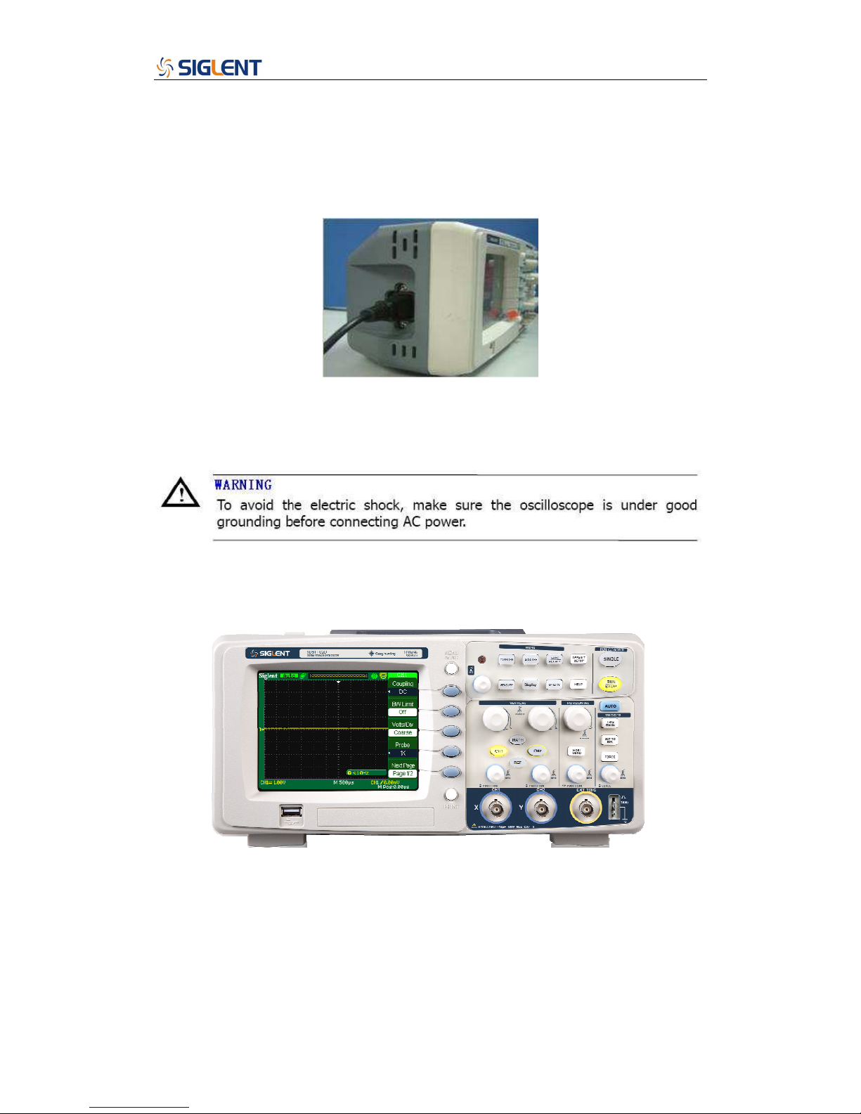
Power-On Inspection
Normal operating voltage for DS1000CA series digital oscilloscope is the range of 100-240VRMS
with the frequency from 45Hz to 440Hz. Connect one terminal of the power cord to the socket in
left side of the oscilloscope and the other to the power source.
Picture 2-1 Connect power line
Press the button on top of oscilloscope, some keys on the front panel will be lighted for about 6
seconds until the normal display appears. And then you can operate the oscilloscope.
After power-on, the oscilloscope performs the self test automatically. After the test, press the
“DEFAULT/SETUP” button, then recall the Factory settings.
Picture 2-2 Power-On Inspecting
 Loading...