

Page 1
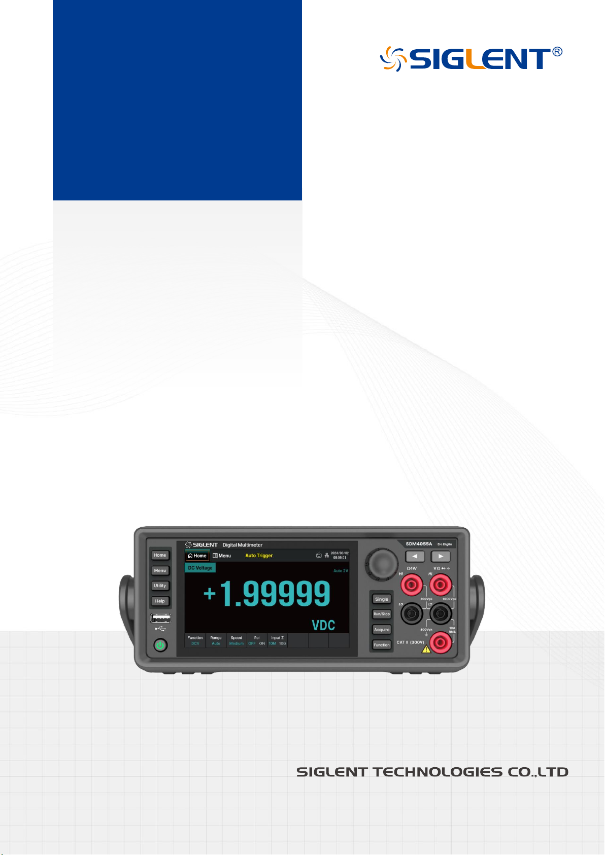
SDM4055A
Digital Multimeter
QuickStart
EN01A
Page 2

Page 3

SDM4055A Quick Start 1
Copyright Information
Declaration
SIGLENT products are protected by patent law in and outside of P.R.C.
SIGLENT
reserves the right to modify or change parts of or all the specifications or pricing policies at the
company’s sole decision.
Information in this publication replaces all previously corresponding material.
Any method of copying, extracting, or translating the contents of this manual is not allowed without the
permission of
SIGLENT
.
Note: SIGLENT
is the registered trademark of SIGLENT TECHNOLOGIES CO., LTD.
Page 4

2 SDM4055A Quick Start
Contents
Copyright Information ............................................................................................................ 1
General Safety Summary ...................................................................................................... 3
Safety Terms and Symbols .................................................................................................... 4
Allgemeine Sicherheits
ü
bersicht .......................................................................................... 5
Sicherheitsbegriffe und symbole ............................................................................................ 6
Mechanical Dimensions ......................................................................................................... 7
Panel Introduction .................................................................................................................. 8
Preparation Before Use ....................................................................................................... 10
User Interface ................................................................................................ ...................... 12
Basic Operations ................................................................................................................. 13
Troubleshooting ................................................................................................................... 16
More Information ................................................................................................................. 16
Page 5

SDM4055A Quick Start 3
General Safety Summary
Carefully read the following safety precautions to avoid any personal injury or damage to the instrument and
any products connected to it. To avoid potential hazards, please use the instrument as specified.
Use the Proper Power Cord
Ground the Instrument
The instrument is grounded through the protective earth conductor of the power cord. To avoid electric
shock, please make certain the instrument is grounded correctly before connecting its input or output
terminals.
Connect the Signal Cable Correctly
The potential of the signal cable ground is float to the earth ground. Do not touch the signal wire while
connected to high voltage.
Look Over All Terminal Ratings
Do not operate with suspected failures
Avoid Exposed Circuits and Components
Do Not Operate Without Covers
Use Only the Specified Fuse
Use Proper Overvoltage Protection
Antistatic Protection
Keep Good Ventilation
Only Qualified Technical Personnel Can Perform Maintenance Procedures
Do Not Operate in Wet or Damp Conditions
Do Not Operate in Flammable or Explosive Environment.
Keep the Surface of the Instrument Clean and Dry
Prevent Fire or Personal Injury
The Disturbance Test of All the models Meets the Limit Values of A in the Standard of EN 613261:2013
Page 6
4 SDM4055A Quick Start
Safety Terms and Symbols
Terms in this manual.
Terms may appear in this manual:
WARNING:
Warning statements indicate the conditions and behaviors that could result in injury or loss
of life.
CAUTION:
Caution statements indicate the conditions and behaviors that could result in damage to
this product or other properties.
CAT II (300V)
: IEC Measurement Category II. Inputs may be connected to mains (up to 300VAC) under
Category II overvoltage conditions.
Terms used on the instrument.
Terms may appear on the instrument:
DANGER
indicates an injury or hazard that may immediately happen.
WARNING
indicates an injury or hazard that may not immediately happen.
CAUTION
indicates that a potential damage to the instrument or other property might occur.
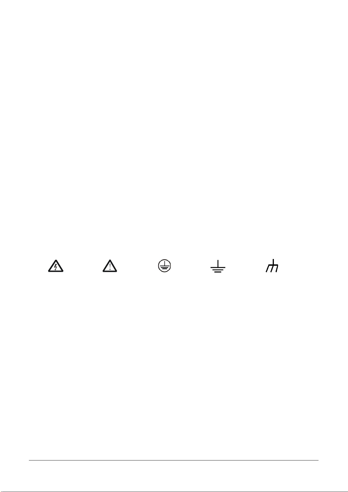
Symbols used on the instrument.
Symbols may appear on the instrument:
Hazardous
Voltage
Warning
Protective
Earth Ground
Test Ground
Chassis
Ground
Page 7

SDM4055A Quick Start 5
Allgemeine Sicherheitsübersicht
Lesen Sie die folgenden Sicherheitshinweise sorgfältig durch, um Verletzungen oder Schäden am Gerät
und an den daran angeschlossenen Produkten zu vermeiden. Um mögliche Gefahren zu vermeiden,
verwenden Sie das Gerät bitte wie angegeben.
Verwenden Sie ein geeignetes Netzkabel
Erden Sie das Gerät
Das Gerät ist über den Schutzleiter der Netzleitung geerdet. Um einen elektrischen Schlag zu vermeiden,
vergewissern Sie sich bitte, dass das Gerät korrekt geerdet ist, bevor Sie die Eingangs- oder
Ausgangsklemmen des Geräts anschließen.
Schließen Sie das Messkabel richtig an
Das Potential des Signalkabels unterscheidet sich von dem der Erde. Berühren Sie das Signalkabel nicht,
wenn es mit einem Hochspannungskabel verbunden ist.
Überprüfen Sie die Nennwerte aller Klemmen
Betreiben Sie das Gerät nicht bei vermuteten Defekten
Vermeiden Sie freiliegende Schaltkreise oder Komponenten
Nicht ohne Abdeckungen arbeiten
Nur die angegebene Sicherung verwenden
Verwenden Sie den richtigen Überspannungsschutz
Schutz vor Elektrostatik
Für gute Belüftung sorgen
Nur qualifiziertes technisches Personal kann Wartungsmaßnahmen durchführen
Nicht in feuchter Umgebung betreiben
Betreiben Sie das Gerät nicht in explosionsgefährdeten Umgebungen
Halten Sie die Produktoberflächen sauber und trocken
Verhindern Sie Feuer oder Personenschäden
Der Störtest aller Modelle erfüllt die Grenzwerte von A in der Norm EN 61326-1:2013
Page 8
6 SDM4055A Quick Start
Sicherheitsbegriffe und symbole
Begriffe in diesem Handbuch.
Diese Begriffe können in diesem Handbuch vorkommen:
WARNUNG
Warnhinweise weisen auf Bedingungen oder Praktiken hin, die zu Verletzungen oder zum
Verlust des Lebens führen können.
VORSICHT
Vorsichtshinweise weisen auf Bedingungen oder Praktiken hin, die zu Schäden an diesem
Produkt oder anderen Gegenständen führen können.
CAT II (300V)
: IEC Messkategorie II. Die Eingänge können unter Überspannungsbedingungen der
Kategorie II an das Netz (bis 300VAC) angeschlossen werden.
Begriffe auf dem Produkt.
Diese Begriffe können auf dem Produkt erscheinen:
DANGER
Weist auf direkte Verletzungen oder Gefahren hin, die auftreten können.
WARNING
Weist auf mögliche Verletzungen oder Gefährdungen hin, die auftreten können.
CAUTION
Weist auf mögliche Schäden am Gerät oder an anderen Gegenständen hin, die eintreten
können.
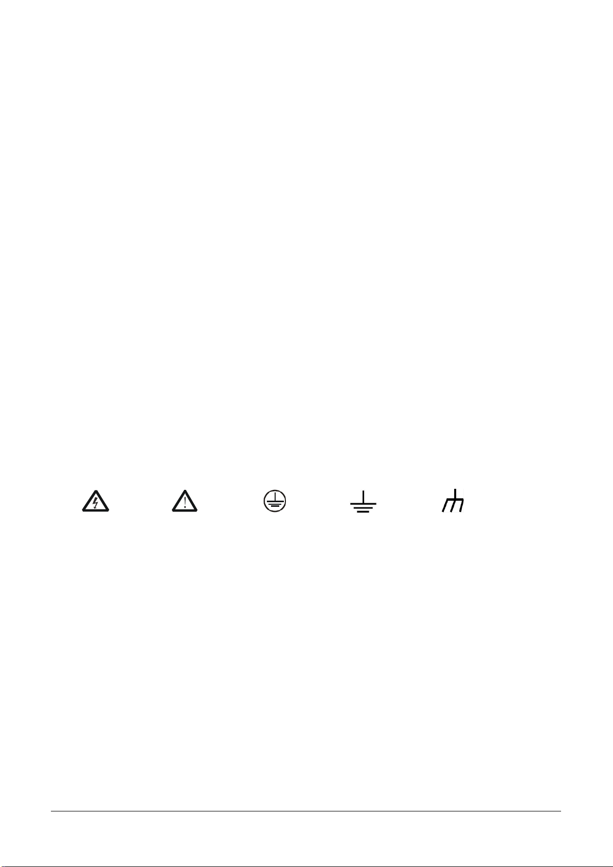
Symbole auf dem Produkt.
Diese Symbole können auf dem Produkt erscheinen:
Hazardous
Voltage
Warning
Protective
Earth Ground
Test Ground
Chassis
Ground
Page 9
SDM4055A Quick Start 7
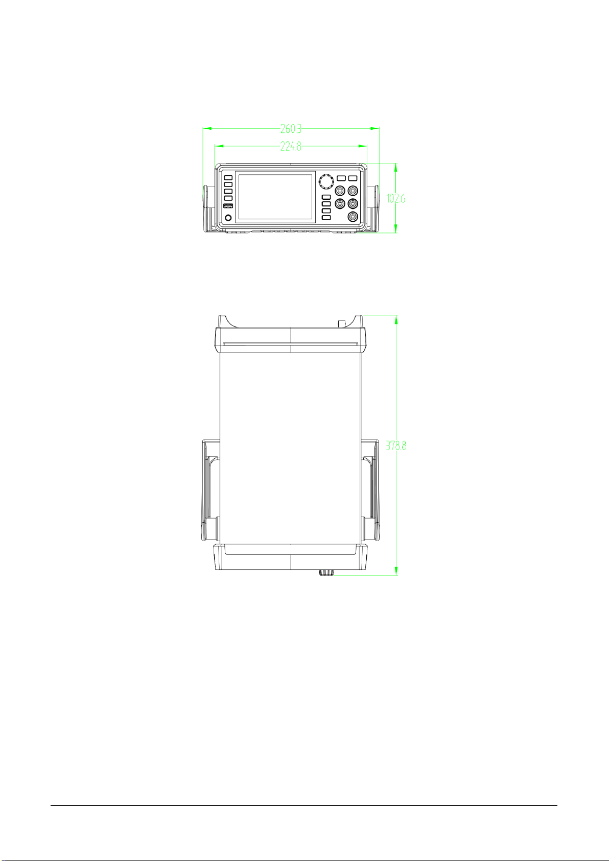
Mechanical Dimensions
Front View
Top View
Page 10
8 SDM4055A Quick Start
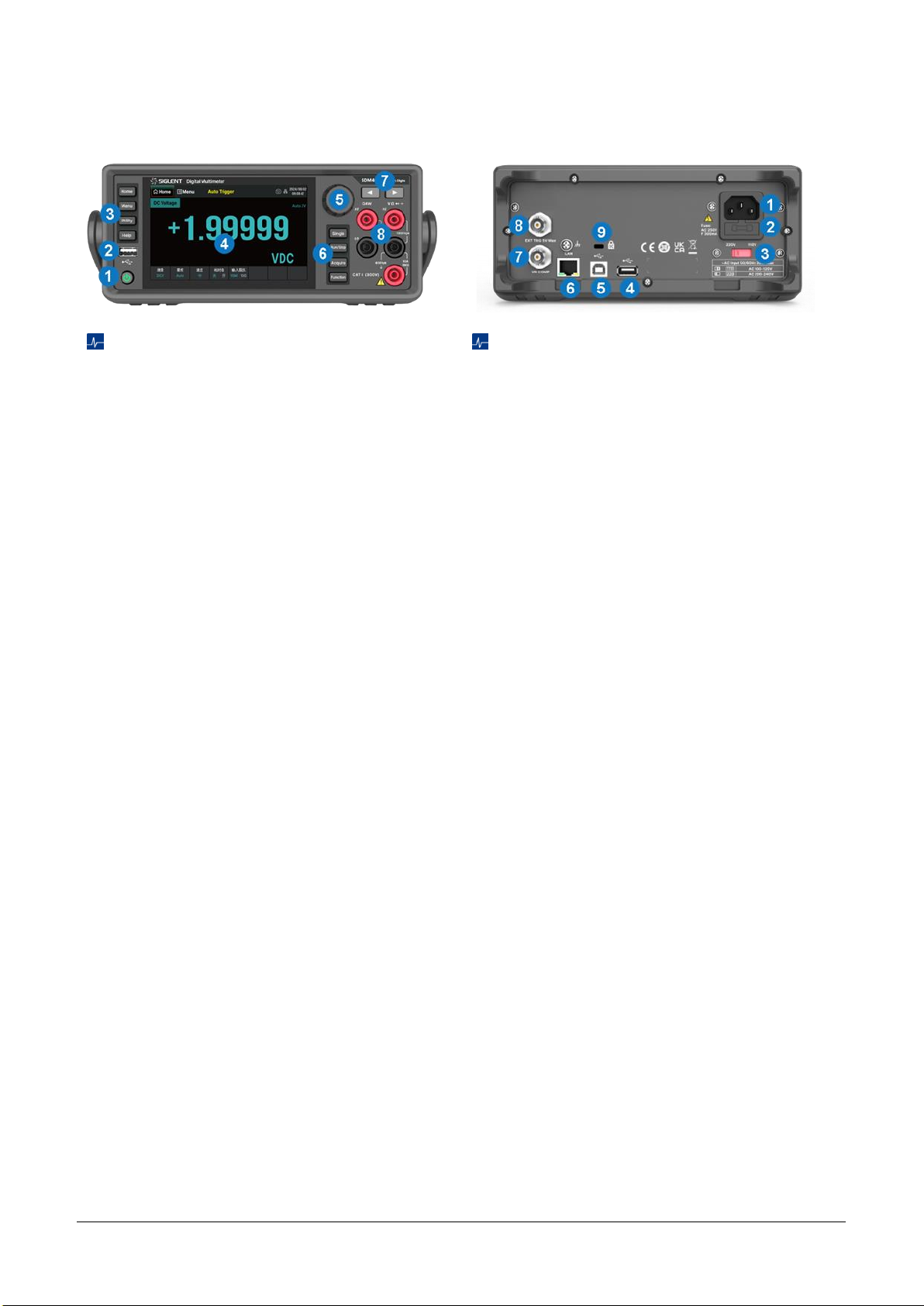
Panel Introduction
Front Panel
1.
Power Key
Short/long press the key to turn
on/off the instrument.
2.
USB Host
By using this interface, you can
store the current state or measurement data
into USB storage device, and you can also
read the state files or updated firmware from
USB storage device.
3.
Menu Operation Buttons
Press any softkey
to activate the corresponding menu.
4.
Touchable Display Screen
Display the
menu and measurement parameter settings
for the current function, system status, and
prompt messages. Related operations can
be achieved by touching the screen area with
fingers.
5.
Knob
6.
Trigger and Measurement Function
Buttons
7.
Left/Right Directional Buttons
Move the
cursor, with the same function as
counterclockwise/clockwise rotation of the
knob.
8.
Signal Input Terminals
The measured
signal (device) will be connected into the
multimeter through these terminals. Different
measurement functions have different
connections methods. For details, please
refer to “Measurement Connections”.
Rear Panel
1.
Power Socket
The multimeter accepts two
types of AC supplies. Please use the power
cord provided in the accessories to connect
the multimeter to the AC power through this
socket.
Note
: A proper voltage scale must be first
selected (through the AC Voltage Selector)
before power connection.
2.
Power Fuse
3.
AC Voltage Selector
Select a proper voltage
scale (110 V or 220 V) according to the AC
supply used.
4.
USB Host
5.
USB Device
Connect the PC through this
interface. You can use SCPI commands or PC
software to control SDM4055A remotely.
6.
LAN
Through this interface, the multimeter
can be connected to the network for remote
control.
7.
VMC Output
The multimeter outputs a 5V
pulse from this port every time it completes a
sampling.
8.
Ext Trigger
Trigger the multimeter by
connecting a trigger pulse through the [EXT
TRIG] connector. Note the external trigger
source must be selected.
9.
Instrument Lock Hole
You can use the safety
lock (please purchase it yourself) to lock the
multimeter in a fixed place if necessary.
Page 11
SDM4055A Quick Start 9
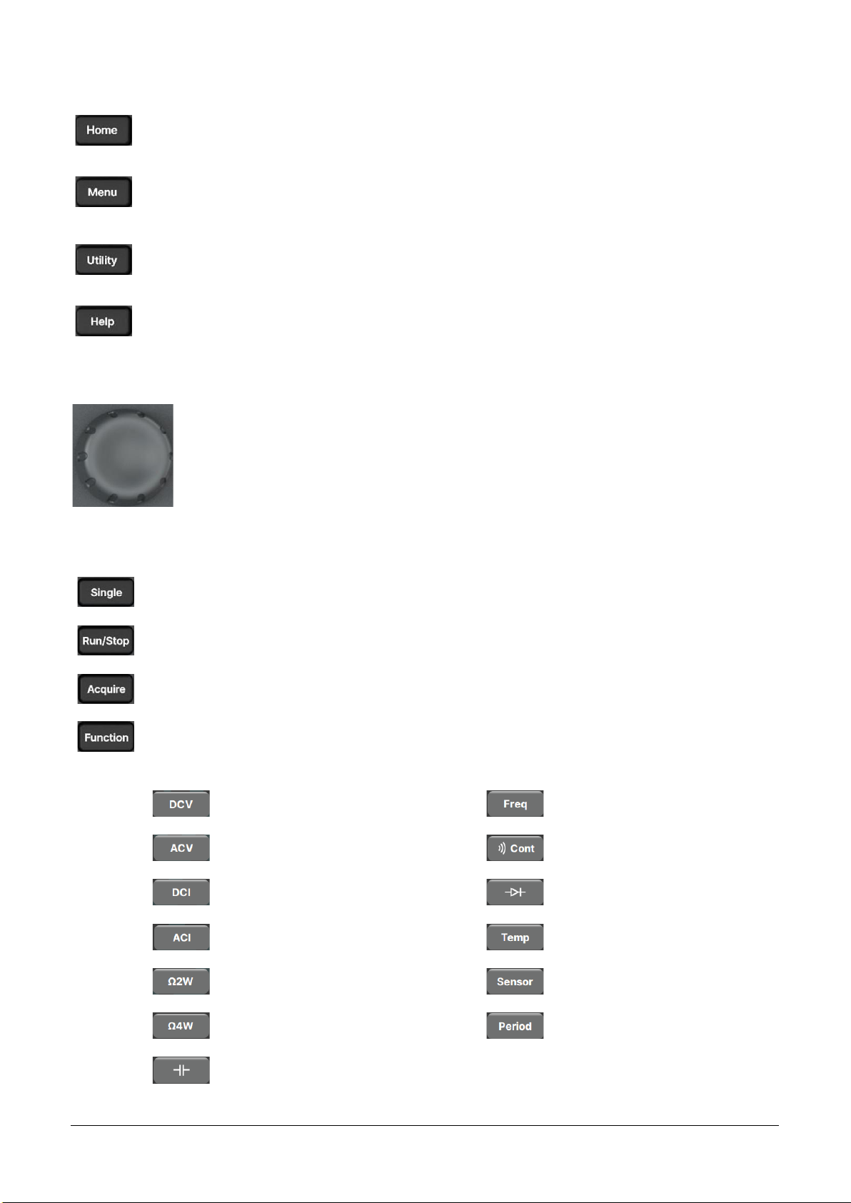
Menu Operation Buttons
Set measurement functions and corresponding parameters related to the functions.
Select or set parameters about Utility, Math, Acquire, Display, Dual Function, Probe Hold and
Help.
Set the system functions about Store/Recall, File Management, I/O Config, Test Management,
System Setting and Date Time Edit.
Provide help information.
Knob
Rotate the knob clockwise/counterclockwise to move the cursor, press down to select
the menu item where the cursor is located or turn on/off the menu item function.
Trigger and Measurement Functions Buttons
Single Trigger.
Auto Run/Stop.
Set up functions such as Acquire, Trigger Setting, VMC Out, and Save Readings.
Open the measurement function selection menu to select the following measurement
functions:
DC voltage measurement
Frequency measurement
AC voltage measurement
Continuity measurement
DC current measurement
Diode measurement
AC current measurement
Temperature measurement
2-wire resistance measurement
Sensor measurement
4-wire resistance measurement
Period measurement
Capacitance measurement
Page 12
10 SDM4055A Quick Start
Preparation Before Use
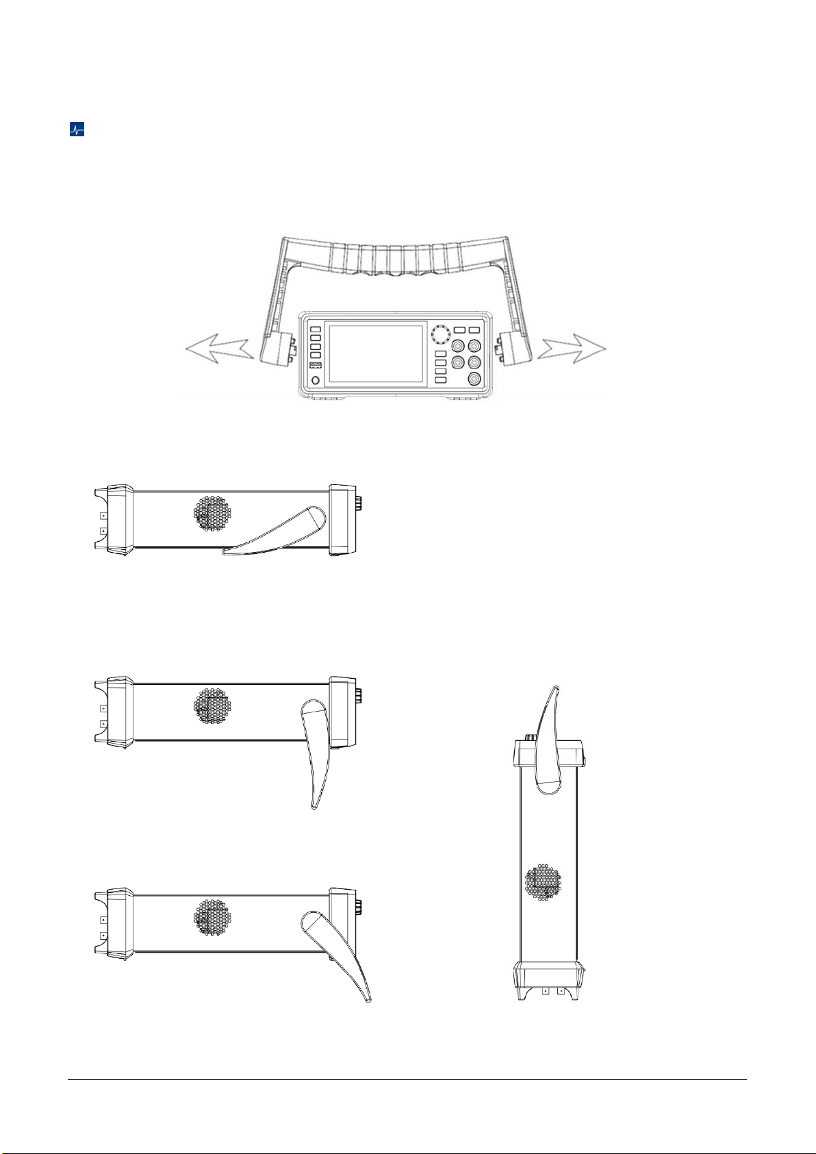
To Adjust the Handle
Please grip the handle by the two sides and pull it outward to adjust the handle position of SDM4055A.
Then rotate the handle to the appropriate position. Please operate as the following figure:
Handle Adjustment
Viewing Position
Carrying Position
Page 13
SDM4055A Quick Start 11
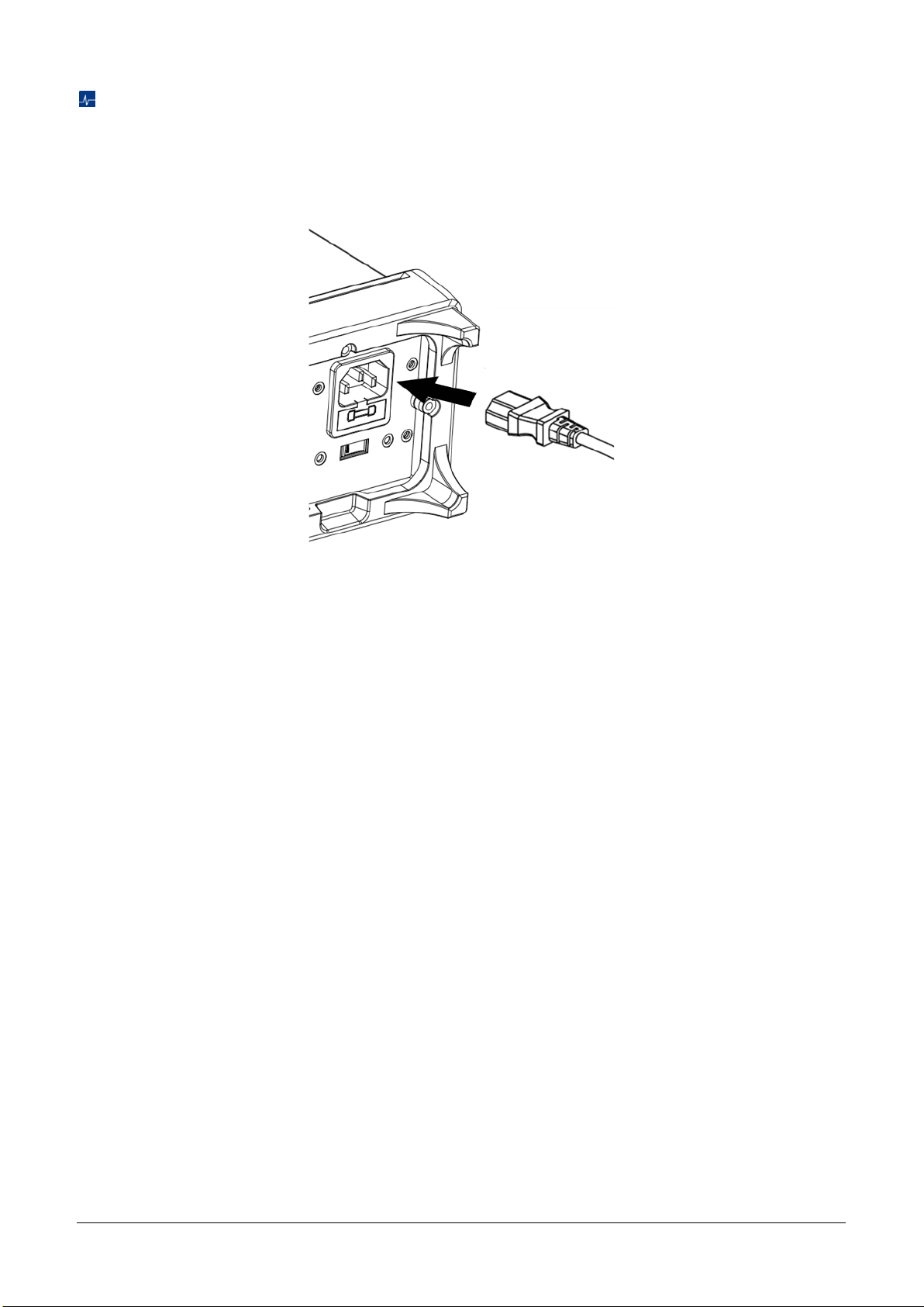
Start the Multimeter
Before connect the instrument to a power source, please select the AC voltage in the AC voltage selector
on the rear panel of your multimeter according to the power supply. Then connect the power cord as shown
in the following figure.
Connect Power Cord
Press the power key on the front panel to start up the multimeter. If the multimeter does not start normally,
please refer to the relevant content and steps of the Troubleshooting for inspection.
Page 14
12 SDM4055A Quick Start
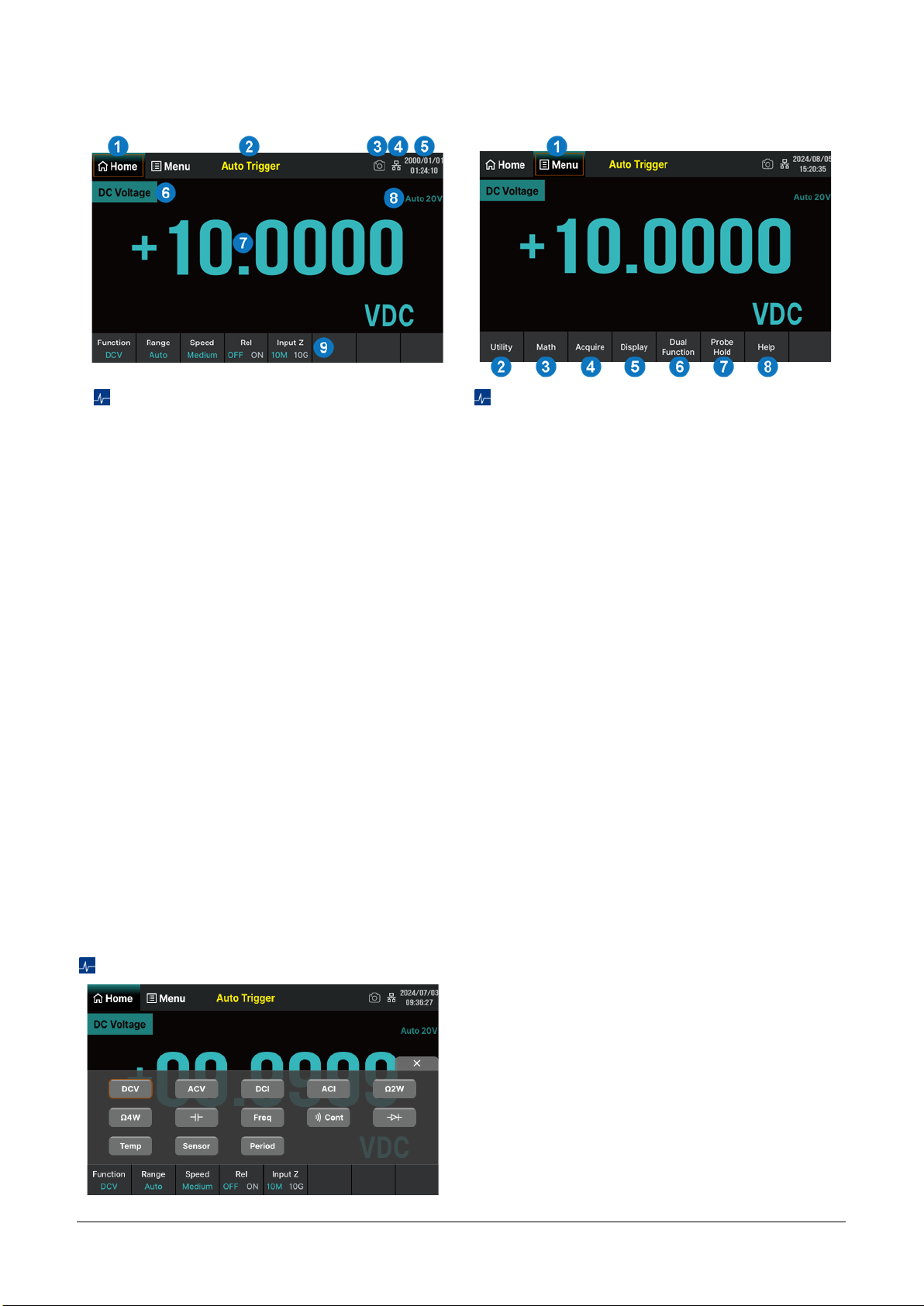
User Interface
Home Interface
1. Home. Functionally equivalent to the
"Home" button on the left side of the front
panel
2. Trigger mode
3. Quick screenshot identification
4. LAN status icon
5. Date and time display area
6. Measurement function
7. Measurement result
8. Current range in use
9. Operation menu. Select the measurement
function and set the parameters for this
function
Menu Interface
1. Menu. Functionally equivalent to the "Menu"
button on the left side of the front panel
2. Utility. Set up functions about system
settings. Functionally equivalent to the
"Utility" button on the left side of the front
panel
3. Math. Enable or disable Statistics, Limits,
dB/dBm, and Rel Value functions
4. Acquire. Set trigger mode (Continue / Data
Log), Trigger Setting, VMC Out, and Save
Readings
5. Display. Set the display mode to Numbers /
Bar / Trend / Histogram
6. Dual Function. Synchronously display two
kinds of characteristics of the same signal
7. Probe Hold. Up to 8 of the latest measured
readings can be displayed simultaneously
8. Help. Built in help system for convenient
viewing of help information
Measurement Function
Click on the "Function" menu at the bottom left of
the home interface, or click on the "Function" button
on the front panel to enter the measurement
function selection interface (as shown in the left
figure). According to the measurement
requirements, touch or use the knob to select the
function buttons on the interface and set the
relevant parameters for that function.
Page 15
SDM4055A Quick Start 13
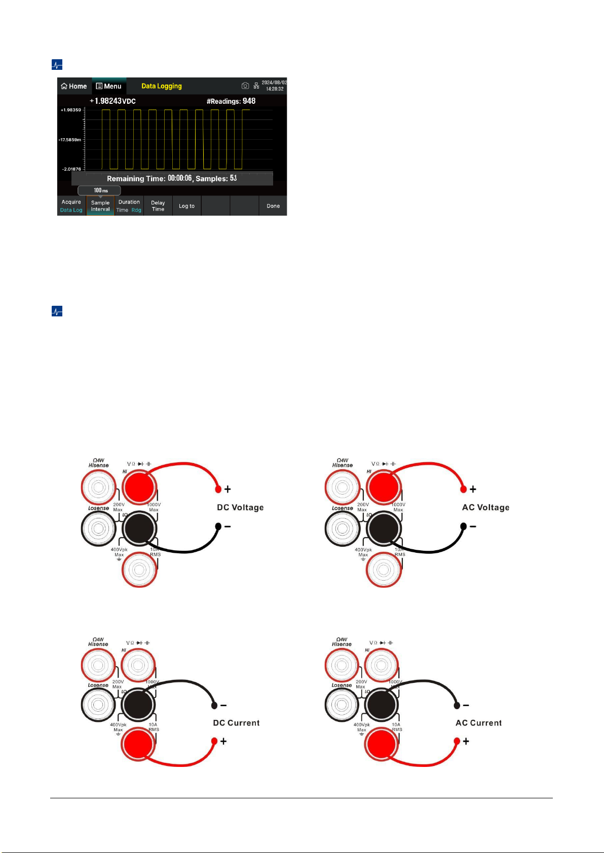
Data Log Function
The Data Log function supports recording of AC/DC
voltage, AC/DC current, resistance, capacitance,
frequency, period, and temperature data. The
interval time can be set within the range of
0.1s~3600s. When logging to Memory, the
maximum number of readings is 2M; When logging
to the File(s), the maximum number of readings is
360M. Up to 100 hours of logging time.
Basic Operations
Measurement Connections
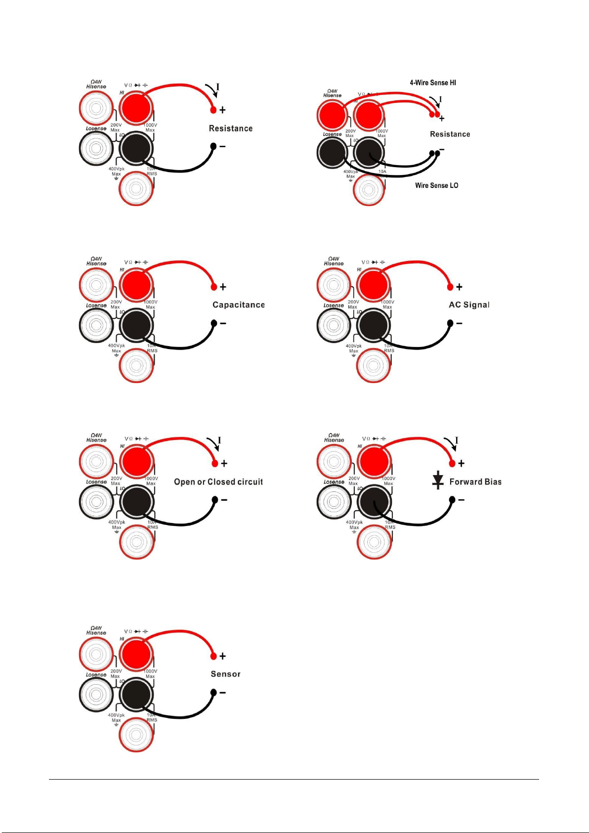
The multimeter is designed with many measurement functions. After selecting the desired measurement
function, please connect the signal (device) under test to the multimeter according to the method below. Do
not discretionarily switch the measurement function when measuring as it may cause damage to the
multimeter. For example, when the test leads are connected to the related current terminals, AC voltage
measurement should not be taken.
DCV Measurement (DCV)
ACV Measurement (ACV)
DCI Measurement (DCI)
ACI Measurement (ACI)
Page 16
14 SDM4055A Quick Start
Resistance Measurement (2WR)
Resistance Measurement (4WR)
Capacitance Measurement (Cap)
Frequency/Period Measurement (Freq/Period)
Continuity Measurement (Cont)
Diode Measurement (Diode)
Temperature Measurement (Temp)
(For RTD and thermocouple sensors)
Page 17
SDM4055A Quick Start 15
To Use the Built-in Help System
To obtain built-in help information of the product, please press [Help] to enter help system, then choose the
help item you want and view the corresponding help information.
The built-in help information is listed as the following:
1) Basic measurement
2) Math function
3) Dual display function
4) Save and recall
5) Teach support
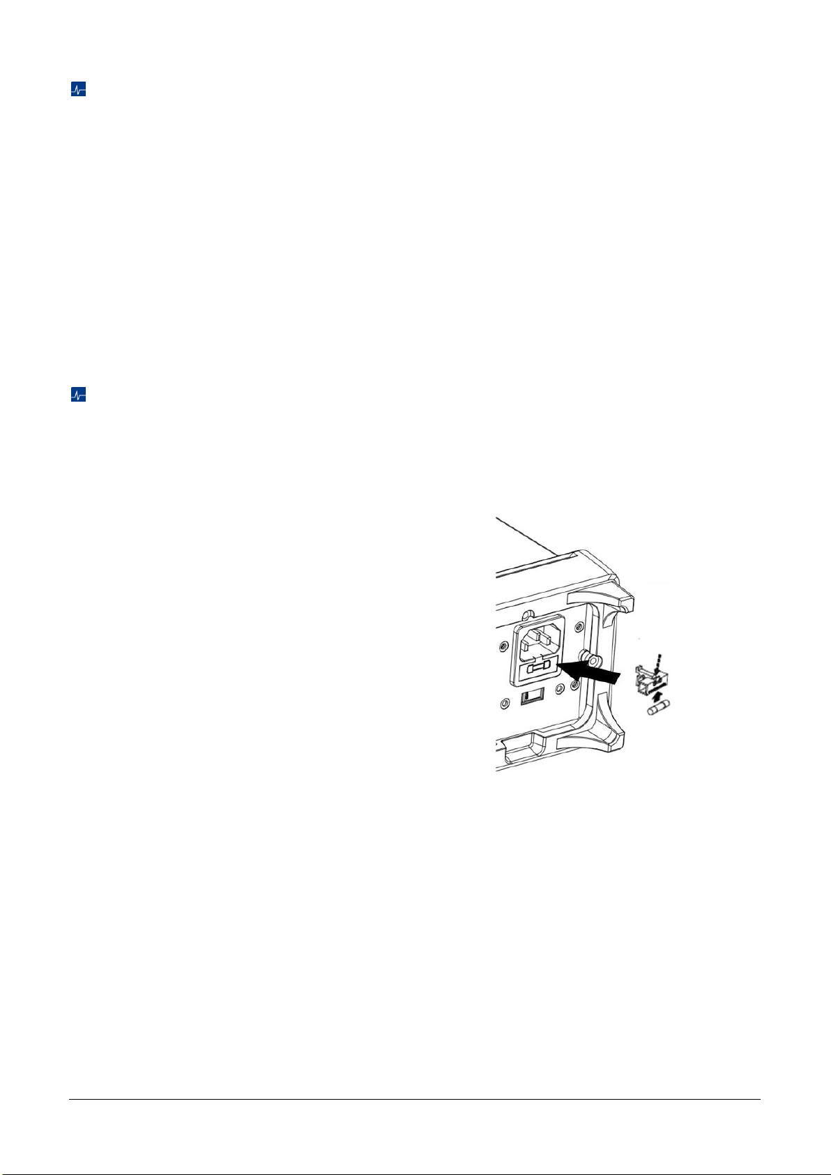
Replace the Power Fuse
The multimeter is already installed with a power fuse before leaving factory. This fuse is a slow melting,
explosion-proof, T315mA, 5x20mm fuse. If you need to replace the fuse, please follow the steps below to
replace it:
1) Turn off the multimeter and remove the power
cord.
2) Press down the block tongue using a straight
screwdriver (in the direction of the dotted arrow
in the figure) and pull out of the fuse seat.
3) Select a proper voltage scale.
4) Replace a specified fuse.
5) Reinstall the fuse seat into the slot.
Replace the Power Fuse
Page 18

16 SDM4055A Quick Start
Troubleshooting
The commonly encountered failures and their solutions are listed below. When you encounter those
problems, please solve them following the corresponding steps. If the problem remains still, please contact
SIGLENT
and provide your device information.
1. If the screen is still dark with nothing displayed after pressing the power key.
1) Check whether the power cord is well connected.
2) Check if the power switch on the front panel is pressed firmly.
3) Check whether the power fuse is burned out. If the fuse needs to be changed, please use the
specified fuse.
4) Restart the instrument after finishing the above inspections.
5) If the instrument still can’t start up properly, please contact
SIGLENT
.
2. The reading doesn’t change when a current signal is input.
1) Check whether the test lead is correctly inserted into the HI and LO terminals of current
measurement.
2) Check whether the DCI or ACI measurement function is enabled.
3) Check whether the DCI measurement function is used to measure AC current.
3. The reading is abnormal when a voltage signal is input.
1) Check whether the test lead is correctly inserted into the HI and LO terminals of voltage
measurement.
2) Check whether the DCV or ACV measurement function is enabled.
3) Check whether the DCV measurement function is used to measure AC voltage.
4. The USB storage device cannot be identified.
1) Check whether the USB storage device is in good condition.
2) Make sure the USB storage device you used is a flash storage device. This instrument does not
support hardware storage type.
3) Restart the instrument and then insert the USB storage device.
4) If the problem persists, please contact
SIGLENT
.
More Information
You can obtain the instrument information and installation status of all options in “system setup” under the
Utility menu. For more information of this product, please refer to the following manuals (you can also
download them from the SIGLENT web site: http://int.siglent.com):
SDM4055A user manual:
Provides detailed introductions of the functions of this instrument.
SDM4055A data sheet:
Provides the main characteristics and specifications of this instrument.
SDM4000A programming manual:
Provides detailed introductions of the SCPI commands and programming of this instrument.
Page 19

Page 20

Follow us on
Facebook: SiglentTech
Headquarters:
SIGLENT Technologies Co., Ltd
Add: Bldg No.4 & No.5, Antongda Industrial
Zone, 3rd Liuxian Road, Bao'an District,
Shenzhen, 518101, China
Tel: + 86 755 3688 7876
Fax: + 86 755 3359 1582
Email: [email protected]
Website: int.siglent.com
North America:
SIGLENT Technologies America, Inc
6557 Cochran Rd Solon, Ohio 44139
Tel: 440-398-5800
Toll Free: 877-515-5551
Fax: 440-399-1211
Email: [email protected]
Website: www.siglentna.com
Europe:
SIGLENT Technologies Germany GmbH
Add: Staetzlinger Str. 70
86165 Augsburg, Germany
Tel: +49(0)-821-666 0 111 0
Fax: +49(0)-821-666 0 111 22
Email: [email protected]
Website: www.siglenteu.com
 Loading...