

SIGLENT SDM3065X User Manual

User Manual
SDM3065X Digital Multimeter
UM06036-E01B
2017 SIGLENT TECHNOLOGIES CO., LTD


SIGLENT
SDM3055 Digital Multimeter I
Copyright and Statement
Copyright
SIGLENT TECHNOLOGIES CO., LTD. All rights reserved.
Trademark Information
SIGLENT is registered trademark of SIGLENT TECHNOLOGIES CO., LTD.
Statement
● SIGLENT products are protected by patent laws in and outside of the P.R.
China.
● SIGLENT reserves the rights to change the specification and price.
● Information in this publication replaces all previous corresponding
published material.
● Contents in this manual are not allowed to be copied, extracted or
translated in any form or by any means without SIGLENT‟s permission.

SIGLENT
II SDM3055 Digital Multimeter
General Safety Summary
Read the following safety precautions carefully to avoid any personal injuries
or damages to the instrument and any products connected to it. To avoid
potential hazards, please use the instrument as specified.
Use proper power line.
It‟s only allowed to use the special power line which is approved by local
state.
Ground the instrument.
The instrument is grounded through the protective terra conductor of the
power line. The ground conductor must be connected to the earth to avoid
electric shock. Make sure the instrument is grounded correctly before
connecting its input or output terminals.
Connect the signal wire correctly
The potential of the signal wire is equal to the earth, so do not connect the
signal wire to a high voltage.
Observe all terminal ratings
Please observe all ratings and sign instructions on the instrument to avoid fire
or electric shock. Before connecting the instrument, please read the manual
carefully to gain more information about the ratings.
Do not operate with suspected failures
If you suspect that the product is damaged, please contact SIGLENT‟s
qualified service personnel to inspect it. Any repair and adjustment to the
product or replacing a component should be done by qualified personnel
only.
Avoid circuit or wire exposure
Don‟t touch exposed contacts or components when the power is on.
Don’t operate without covers.
Don‟t operate the instrument with covers or panels removed.
Use proper fuse.
It‟s only allowed to use the specified fuse for the instrument.
Use proper over-voltage protection.
Make sure there is no over-voltage (like voltage caused by thunder and
lightning) reaching to the instrument, otherwise the operator may suffer an
electric shock.

SIGLENT
SDM3055 Digital Multimeter III
Antistatic protection.
Static electricity will cause damages to the instrument, so test in antistatic
areas as far as possible. Ground its inner and outer conductors to release the
static electricity temporarily before connecting the cable to the instrument.
Keep good ventilation.
Improper ventilation will cause the rise of the instrument‟s temperature. Keep
good ventilation and check the vent and fan regularly when using it.
Keep the surface of the instrument clean and dry.
Do not operate in wet or damp conditions.
Do not operate in flammable or explosive environment.
The disturbance test of all the models meets the limit values of A in the
standard of EN 61326-1:2013.
Input terminal protection limitation
Protection limitation is defined for the input terminal:
1. Main input(HI and LO)terminal
HI and LO terminals are used for Voltage, Resistance, Capacitance,
Continuity, Frequency and Diode measurement. Two protection limitations
are defined:
HI-LO protection limitation: 1000VDC or 750AVC. It‟s the maximum
measurable voltage. The limitation can be expressed as 1000Vpk.
LO-ground protection limitation : LO terminal can “float” 500Vpk
relative to the ground safely. The maximum protection limitation of HI terminal
relative to the ground is 1000Vpk. Therefore, the sum of the “float” voltage
and the measured voltage can‟t exceed 1000Vpk.
2. Sampling (HIsense and LOsense) terminal
HIsense and LOsense are used for 4-wire Resistance measurement. Two
protection limitations are defined:
HIsense-LOsense protection limitation: 2000Vpk.
LOsense-LOsense protection limitation: 2Vpk.

SIGLENT
IV SDM3055 Digital Multimeter
3. Current input (I) terminal
I and LO terminals are used for current measurement. The maximum
current which go through the I terminal is limited to 10A by the fuse on the
back panel.
NOTE:
Voltage on the current input terminal corresponds to voltage on LO terminal.
To keep good protection, only use the fuse of specified type and level to
replace this fuse.
IEC Measurement Category II Over-voltage Protection
SDM3065X Digital Multimeter provides over-voltage protection for
line-voltage mains connections meeting both of the following conditions to
avoid the danger of electric shock:
The HI and LO input terminals are connected to the mains under
Measurement Category II conditions as following.
The maximum line voltage of the mains is 600VAC.
WARNING:
IEC Measurement Category II includes electrical devices connected to mains
at an outlet on a branch circuit, such as most small appliances, test
equipments, and other devices that plug into a branch outlet or socket.
SDM3065X is capable of making measurements with the HI and LO inputs
connected to mains in such devices (up to 600VAC) or the branch outlet itself.
However, the HI and LO terminals of SDM3065X can‟t be connected to
mains in permanently installed electrical devices such as the main
circuit-breaker panels, sub-panel disconnected boxes and permanently wired
motors. Such devices and circuits are prone to exceed the protection limits of
SDM3065X.
NOTE:
Voltages above 600VAC only can be measured in circuits that are isolated
from mains. However, there may be transient over-voltage in circuits that are
isolated from mains. SDM3065X is able to withstand occasional transient
over-voltage up to 4000Vpk. Please don‟t use this instrument to measure
circuits that transient over-voltage may exceed this level.
SIGLENT
SDM3055 Digital Multimeter V
Safety Terms and Symbols
Terms in this manual. Terms may appear in this manual.
Terms used on the instrument. Terms may appear on the instrument:
DANGER indicates an injury or hazard that may immediately happen.
WARNING indicates an injury or hazard that may not immediately happen.
CAUTION indicates that a potential damage to the instrument or other
property might occur.
Symbols used on the instrument. Symbols may appear on the instrument.
WARNING: Warning statements indicate the conditions and
behaviors that could result in injury or loss of life.
CAUTION: Caution statements indicate the conditions and
behaviors that could result in damage to this product or other
CAT I (1000V): IEC Measurement Category I. The highest
measurable voltage is 1000Vpk in the HI-LO terminal.
CAT II (600V): IEC Measurement Category II. Inputs may be
connected to mains (up to 600VAC) under Category II overvoltage
Hazardous
Voltage
Protective Earth
Ground
Warning
Test
Ground
Chassis
Ground

SIGLENT
VI SDM3055 Digital Multimeter
Daily Maintenance and Cleaning
Maintenance
When storing or placing the instrument, please avoid the liquid crystal display
from direct sunlight for a long time.
NOTE:
To avoid damages to the instrument or probe, please don‟t place them in mist,
liquid or solvent.
Cleaning
Please often clean the instrument or probe according to the use of them.
Wipe the external ash of the instrument and probe by a soft rag. Be
careful not to scratch the transparent plastic protective screen when cleaning
the liquid crystal screen.
Use a soft rag that has been soaked by water to clean the instrument
after cutting off the power. Or use 75% isopropyl alcohol of water solvent to
get a more thorough cleaning.
NOTE:
To prevent the surface of the instrument or probe from damages, please
don‟t use any corrosive or chemical cleaning reagents.
Please make sure the instrument is already dry before restarting it to
avoid short circuits or personal injuries caused by water.

SIGLENT
SDM3055 Digital Multimeter VII
Introduction of SDM3065X
SDM3065X is a 6½ dual-display instrument, especially fitting to the needs of
high-precision, multifunction, and automation measurements. It realized a
combination of basic measurement functions, multiple math functions, and
display functions, etc.
SDM3065X holds a 4.3 inch color TFT-LCD display screen with 480*272 high
resolutions. Its clear keyboard layout and operation hints make it easier and
agility to use. Besides, it supports multi-interface such as USB Device & Host,
LAN and USB-GPIB (optional), which can meet users‟ demand furthest.
Main Features:
4.3 inch color TFT-LCD display screen with 480*272 high resolutions
Real 6½ digits readings resolution
Up to 150rdgs/S measurement speed
True-RMS AC Voltage and AC Current measurements
1 Gb Nand Flash size, mass storage configuration files and data files
Built-in cold terminal compensation for thermocouple
Support standard SCPI and control software on PC, compatible with
commands of main stream multimeters
Supports dual-display function, Chinese and English menu
Built-in help system, convenient to acquire information
Support USB Device, USB Host, LAN, and GPIB (only for SDM3065XA)
interfaces
Configuration and measured data can be imported or exported via VXI 11,
USBTMC and USB flash drive, which is convenient for users to modify,
view and backup

SIGLENT
VIII SDM3055 Digital Multimeter
Abstract
The manual mainly introduces corresponding information of operating the
SDM3065X Digital Multimeter. It contains these chapters:
Chapter 1 Quick Start
Guide you to prepare the SDM3065X Digital Multimeter and know about the
Front/Back panel and user interface.
Chapter 2 Function and Operation
Introduce the functions and operations of SDM3065X in details.
Chapter 3 Application Examples
Introduce you how to use strong measurement functions of this instrument
easily through some examples.
.
Chapter 4 General Troubleshooting
Provide you some general troubleshooting.
Chapter 5 Appendix
Provide you information about accessories, warranties, troubleshooting,
services and supports.

SIGLENT
SDM3055 Digital Multimeter IX
Content
Copyright and Statement .................................................................................. I
General Safety Summary ................................................................................. II
Safety Terms and Symbols ............................................................................. V
Daily Maintenance and Cleaning ................................................................... VI
Introduction of SDM3065X ............................................................................ VII
Abstract ........................................................................................................ VIII
Chapter 1 Quick Start ................................................................ .................. 1
General Inspection .................................................................................... 2
To adjust the Handle ................................................................................. 3
Appearance and Size................................................................................ 4
Front Panel ............................................................................................... 5
Back Panel ................................................................................................ 8
Start the Multimeter................................................................................. 11
User Interface ......................................................................................... 12
Measurement Connections ..................................................................... 13
To Use the Built-in Help System ............................................................. 16
Chapter 2 Function and Operation ............................................................ 17
Measurement Configuration .................................................................... 18
Range .............................................................................................. 19
Intergration Time and Resolution ..................................................... 21
DC Impedance ................................................................................. 23
Auto Zero ......................................................................................... 24
AC Filter ........................................................................................... 25
Short-circuit Resistance ................................................................ ... 26
Gate Time ........................................................................................ 27
Basic Measurement Functions ................................................................ 28
To Measure DC Voltage .................................................................. 29
To Measure DC Current .................................................................. 31
To Measure AC Voltage .................................................................. 33
To Measure AC Current ................................................................... 35
To Measure Resistance ................................................................ ... 37
To Measure Capacitance ................................................................. 40
To Measure Frequency or Period .................................................... 42
To Test Continuity............................................................................ 44
To Test Diode .................................................................................. 46
To Measure Temperature ................................................................ 48
Dual-display Function ............................................................................. 51
Utility Function ........................................................................................ 53
Store and Recall .............................................................................. 54
Manage File ..................................................................................... 58
I/O Configuration.............................................................................. 59
Board Test ....................................................................................... 61

SIGLENT
X SDM3055 Digital Multimeter
Firmware Update ............................................................................. 64
System Setup .................................................................................. 65
Acquire.................................................................................................... 67
Auto Trigger ..................................................................................... 68
Sample Count .................................................................................. 68
Single Trigger .................................................................................. 69
External Trigger ............................................................................... 70
Help System ........................................................................................... 71
Math Function ......................................................................................... 73
Statistics .......................................................................................... 75
Limits ............................................................................................... 77
dBm ................................................................................................. 79
dB ................................ .................................................................... 80
Relative Value.................................................................................. 81
Display Mode .......................................................................................... 82
Trigger .................................................................................................... 88
Hold Measurement Function ................................................................... 89
Chapter 3 Measurement Tutorial ............................................................... 90
True RMS AC Measurement ................................................................... 90
Crest Factor Errors (non-sinusoidal inputs) ............................................ 91
Loading Errors (AC Voltage) ................................................................... 92
Chapter 4 General Troubleshooting .......................................................... 93
Chapter 5 Appendix ................................................................................... 94
Appendix A: Accessories ........................................................................ 94
Appendix B: Warranty summary ............................................................. 95
Appendix C: Contact SIGLENT ............................................................... 96

SIGLENT
SDM3055 Digital Multimeter 1
Chapter 1 Quick Start
This chapter guides users to quicky get familar with the front and rear panles,
user interface and measurement connections of the multimeter.
This chapter contains the following topics:
General Inspection
Handle Adjustment
Appearance and Size
The Front Panel
The Back Panel
Start the Multimeter
User Interface
Measurement Connections
To Use the Built-in Help System

SIGLENT
2 SDM3055 Digital Multimeter
General Inspection
1. Inspect the shipping container.
Please keep the damaged container or cushioning material until the contents
of the shipment have been checked for completeness and the instrument has
passed both electrical and mechanical tests.
The consigner or carrier shall be liable for the damage to instrument resulting
from shipment. SIGLENT would not be responsible for free maintenance/
rework or replacement of the unit.
2. Inspect the instrument.
In case of any damage, or defect, or failure, notify your SIGLENT sales
representative.
3. Check the accessories.
Check the accessories according to the packing list. If the accessories are
incomplete or damaged, please contact your SIGLENT sales representative.
SIGLENT
SDM3055 Digital Multimeter 3
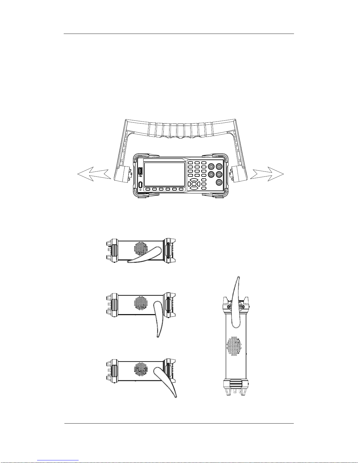
To adjust the Handle
Adjust the handle position of SDM3065X properly to place the instrument
stably so that users can manipulate and observe the display better. Please grip
the handle by the two sides and pull it outward. Then rotate the handle to the
appropriate position. Please operate as the following diagram.
Diagram 1- 1 Handle adjustment
Diagram 1- 2 Horizontal Position Diagram 1- 3 Carrying Position
SIGLENT
4 SDM3055 Digital Multimeter
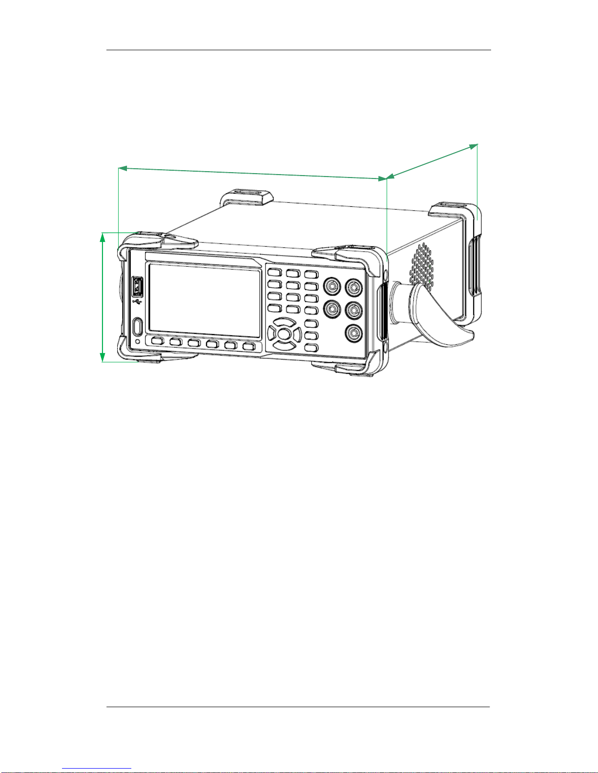
Appearance and Size
Diagram 1- 4 Appearance and Size
260 .27mm
107.21 mm
293.75mm
SIGLENT
SDM3055 Digital Multimeter 5
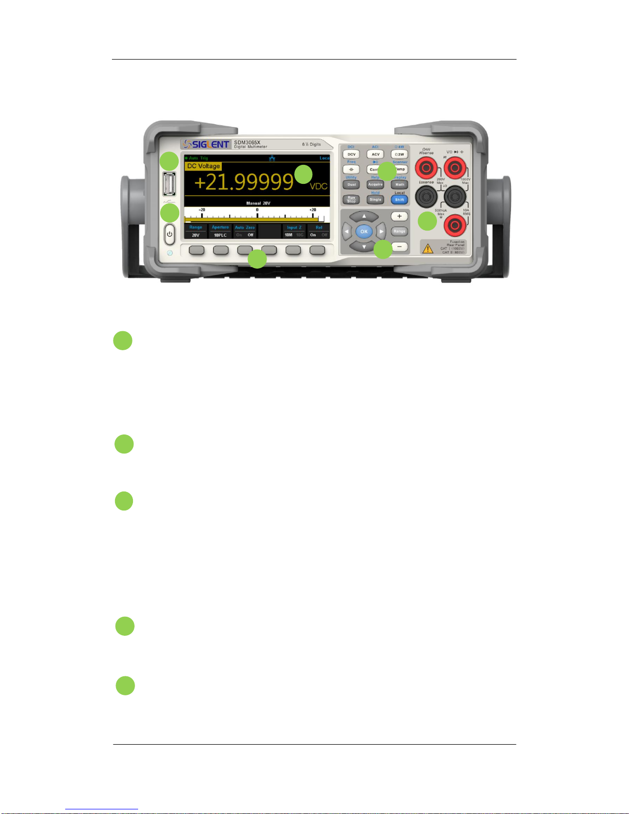
Front Panel
Diagram 1- 5 Front Panel Overview
USB Host
By using this interface, users can store the current state or
measurement data into USB storage device. Users can also read the
state files or updated firmware from USB storage device.
Power Key
Long/short press the key to turn on/off the instrument.
LCD Display
The instrument provides a 4.3 inch color TFT-LCD display screen with
480*272 high resolutions that can the current function menus,
measurement parameter settings, system status, prompt messages and
so on.
Menu Operation Keys
Press any softkey to activate the corresponding menu.
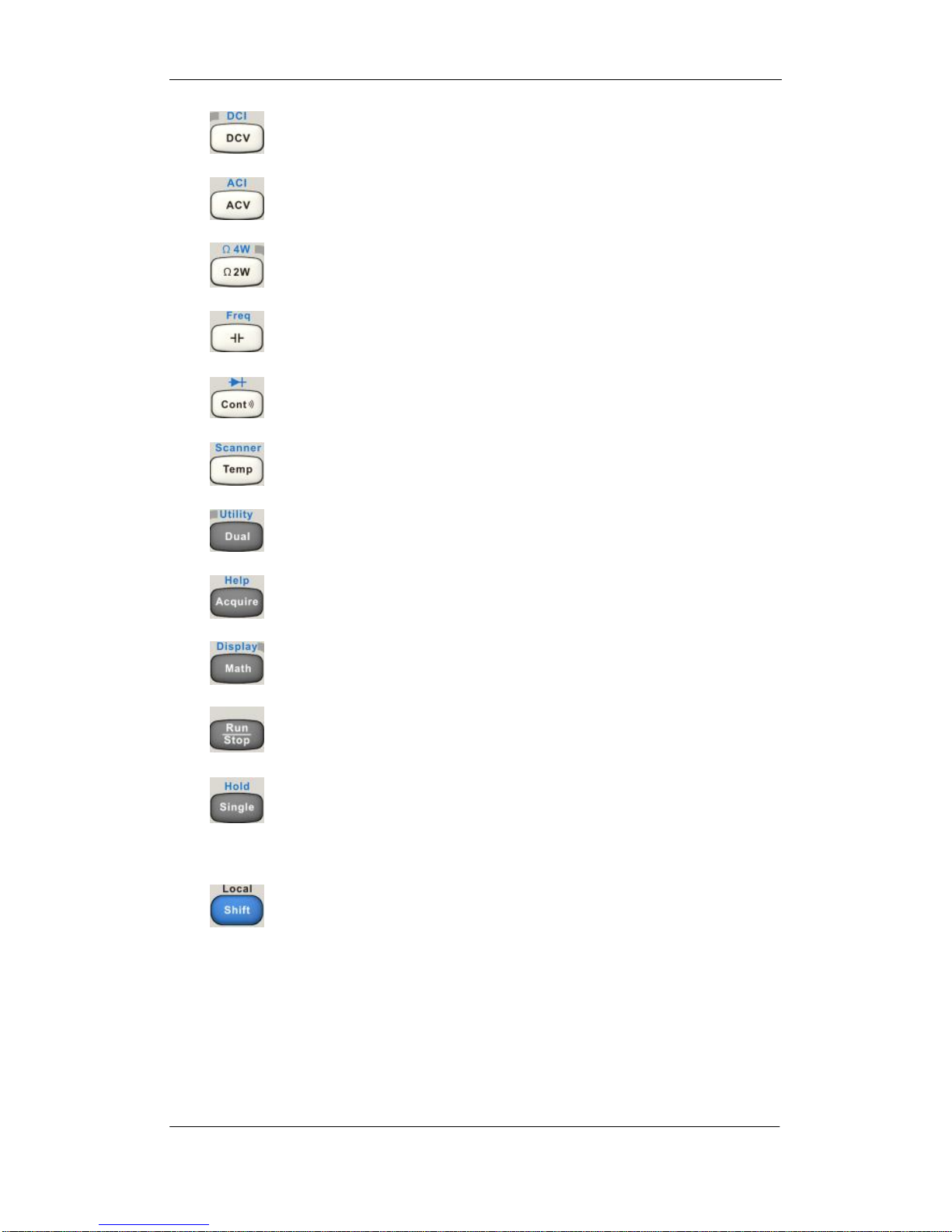
Measurement and Assistant Function Keys
B
ACDEFGCDEAB
SIGLENT
6 SDM3055 Digital Multimeter
DC Voltage /Current Measurement
AC Voltage/ Current Measurement
2-Wire /4-Wire Resistance Measurement
Frequency /Capacitance Measurement
Continuity /Diode Test
Temperature Measurement/
Enable Multiple Scan Card Function
Enable Dual-display Function /Set Up the Utility
Acquire Function /Help System
Math Function /Display Function
Auto Trigger/ Stop
Single Trigger/ Hold Measurement Function
Return to local control of the instrument (when in
Remote mode).
Some of the front panel keys have text above
them. This indicates that the key has a function
that you can access by pressing and releasing
[Shift] before pressing the key.
SIGLENT
SDM3055 Digital Multimeter 7
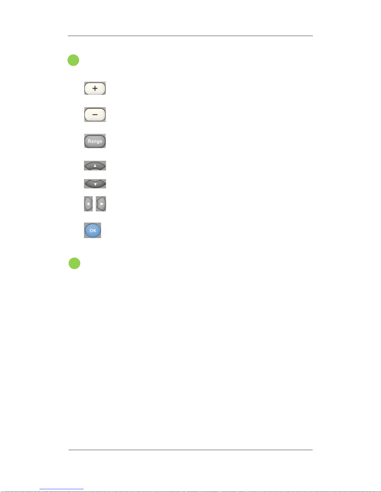
Range and Direction Keys
Increase the measurement range
Decrease the measurement range
Select auto or manual range
Set up measurement parameter
Move the cursor
Page or down
Set up measurement parameter
Move the cursor
Apply the current setting
Signal Input Terminals
The measured signal (device) will be connected into the multimeter
through these terminals. Different measurement objects have different
connection methods. For details, please refer to “Measurement
Connections”.
G
F
SIGLENT
8 SDM3055 Digital Multimeter
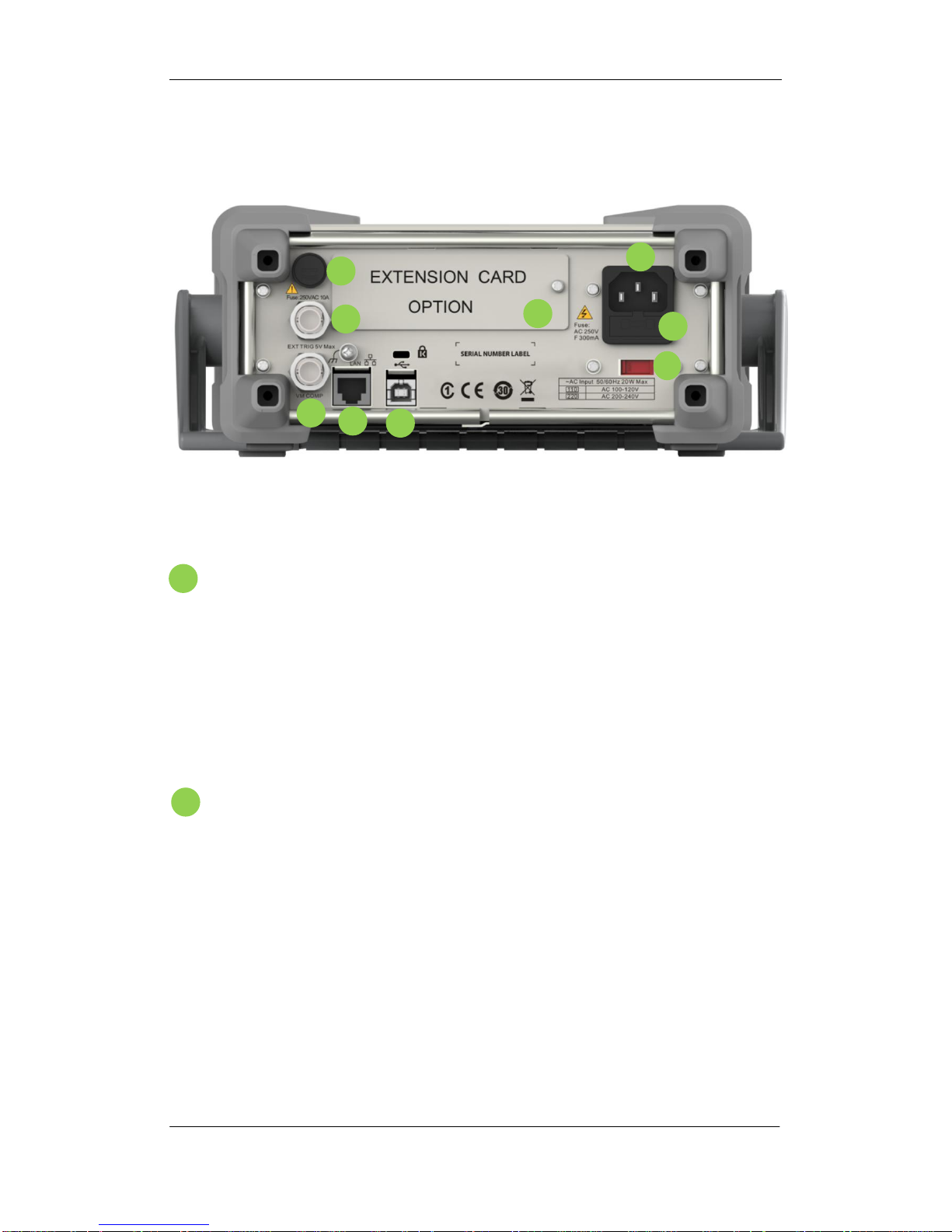
Back Panel
Diagram 1- 6 Back Panel Overview
Power Socket
The multimeter accepts two types of AC supplies. Please use the
power cord provided in the accessories to connect the multimeter to the
AC power through this socket.
Note: a proper voltage scale must be first selected (through the Voltage
Selector) before power connection.
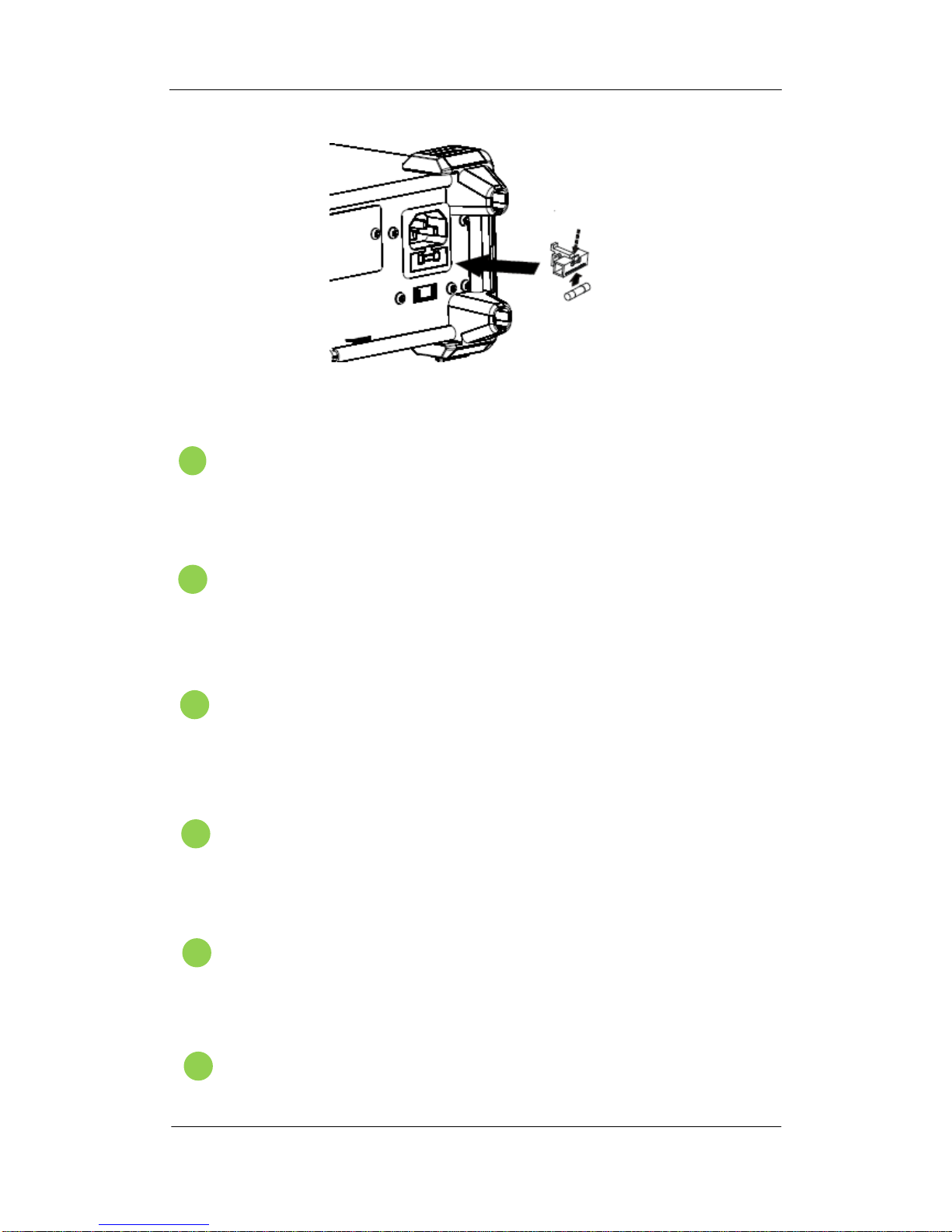
Power Fuse
The multimeter is already installed with a power fuse before leaving
factory. To replace a new one, please:
1) Turn off the multimeter and remove the power cord.
2) Press down the block tongue using a straight screwdriver (in the
direction of the dotted arrow in the figure below) and pull out of the
fuse seat.
3) Select a proper voltage scale.
4) Replace a specified fuse.
5) Reinstall the fuse seat into the slot.
IGH
FEABC
D
A
B
SIGLENT
SDM3055 Digital Multimeter 9
Diagram 1- 7 Change the fuse
AC Voltage Selector
Select a proper voltage scale (110 V or 220 V) according to the AC
supply used.
Inspection card (option)
An optional 16-channel Data Acquisition Module can be installed in
the instrument.
USB Device
Connect the PC through this interface. You can use SCPI commands
or PC software to control SDM3065X remotely.
LAN
Through this interface, the multimeter can be connected to the
network for remote control.
VMC Output
The mutlimeter outputs a low-true pulse from the [VM Comp]
connector after every measurement
Ext trigger
Trigger the multimeter by connecting a trigger pulse through the [Ext
E
G
F
DHC

SIGLENT
10 SDM3055 Digital Multimeter
Trig] connector. Note the external trigger source must be selected.
Current Input Fuse
The multimeter is already installed with a current Input fuse to provide
10 A maximum input protection before leaving factory. To replace a
new one, please:
1) Turn off the multimeter and remove the power cord.
2) Turn the fuse seat counterclockwise as shown in the
figure using a straight screw driver and then pull out the fuse seat
3) Place a new specified fuse.
4) Reinstall the fuse seat into the slot.
Instrument Lockhole
You can use the safety lock to lock the multimeter in a fixed place if
necessary.
I
J
SIGLENT
SDM3055 Digital Multimeter 11
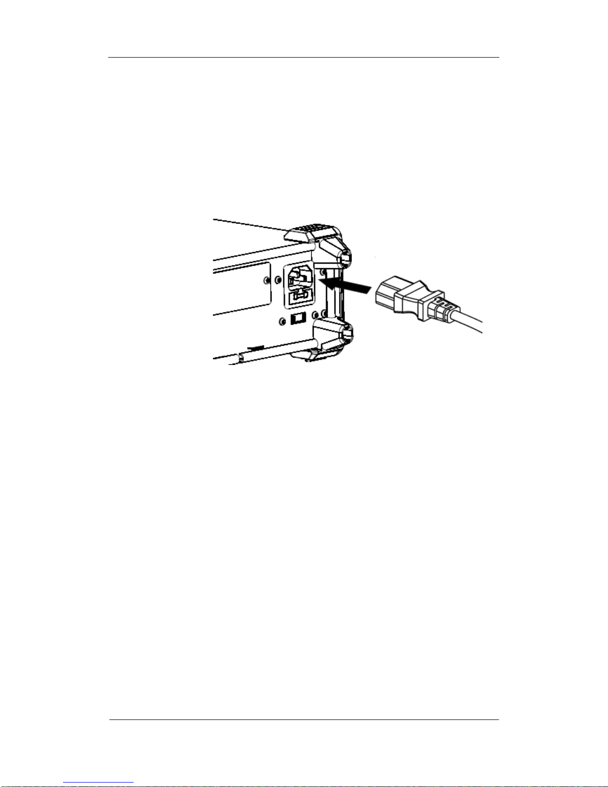
Start the Multimeter
Before connect the instrument to a power source, please select the AC
voltage selector on the rear panel of your multimeter according to the power
supply.Then connect the power cord as shown in the following figure.
Diagram 1- 8 Connect Power Cord
Press the Power key on the front panel to start up the multimeter. If the
multimeter does not starts normally, please:
1. Make sure the power cord is in good connection.
2. Try to restart the multimeter, if it fails, check the power fuse
and replace a new one when necessary.
3. If the problem still remains, please contact SIGLENT.
SIGLENT
12 SDM3055 Digital Multimeter
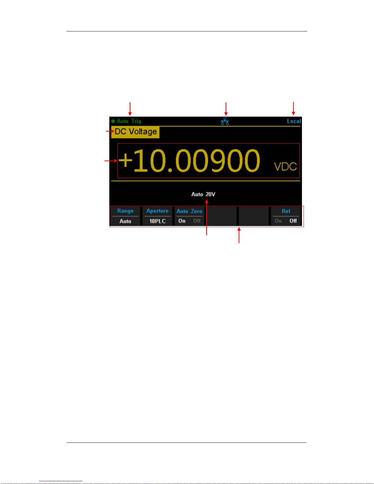
User Interface
Diagram 1- 9 User Interface
Measureme
t
Measureme
t
Trigger
Control Mode
LAN Status Icon
Range
Operation Menu
SIGLENT
SDM3055 Digital Multimeter 13
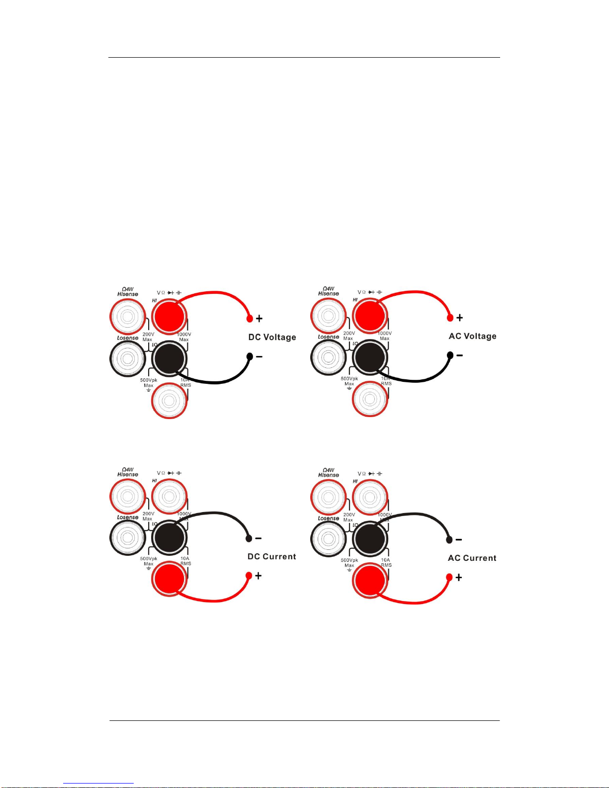
Measurement Connections
SDM3065X is designed with many measurement functions. After selecting
the desired measurement function, please connect the signal (device) under
test to the multimeter according to the method below. Do not discretionarily
switch the measurement function when measuring as it may cause damage
to the multimeter. For example, when the test leads are connected to the
related current terminals, AC voltage measurement should not be taken.
DCV Measurement ACV Measurement
DCI Measurement ACI Measurement
SIGLENT
14 SDM3055 Digital Multimeter
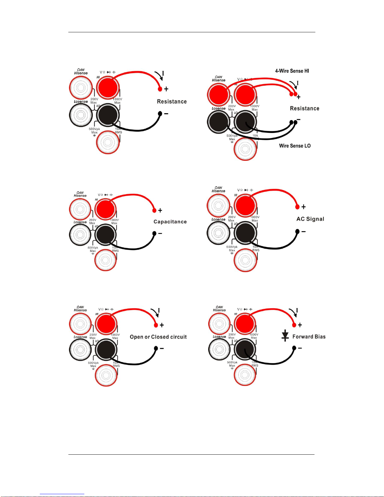
Resistance Measurement (2-wire) Resistance Measurement
(2-wire)
Capacitance Measurement Frequency/Period Measurement
Continuity Measurement Diode Measurement

SIGLENT
SDM3055 Digital Multimeter 15
Temperature Measurement
(For RTD and thermcouple sensors)

SIGLENT
16 SDM3055 Digital Multimeter
To Use the Built-in Help System
To obtain built-in help information of the product, please press 【shift】+
【Acquire】to enter help system, then use the direction keys to choose the help
item you want, finally press 【OK】to obtain help information
The common help information is listed as the following:
1. Basic Measure.
2. Measuring Temperature.
3. Measuring Capacitance.
4. Math Function.
5. Dual-display Function.
6. Saving and Recalling Information.
7. Optional Multiple Scan Card.
8. The convention and Tips of Softkeys.
9. Technical Support.

SIGLENT
SDM3055 Digital Multimeter 17
Chapter 2 Function and Operation
This chapter introduces how to use the functions of the multimeter from the
front panel. The chapter contains the following topics:
To Set the Range
To Set the Resolution
Basic Measurement Functions
Any Sensor Measurement
Preset Mode
Secondary Function Key
Measurement Configuration
Math Operations
Trigger
Save and Recall
Utility
SIGLENT
18 SDM3055 Digital Multimeter
Measurement Configuration
Most measurement parameters are user-defined. Changing a measurement
parameter will change the measurement precision and speed as well as the
input impedance. An appropriate measurement parameter based on the actual
application will ensure faster measurement or higher measurement precision.
The default measurement configurations of the multimeter can ensure the
accuracy of the measurement results in most cases. Users can directly use
these defaults for any measurement or modify the parameters of the
measurement function as required.
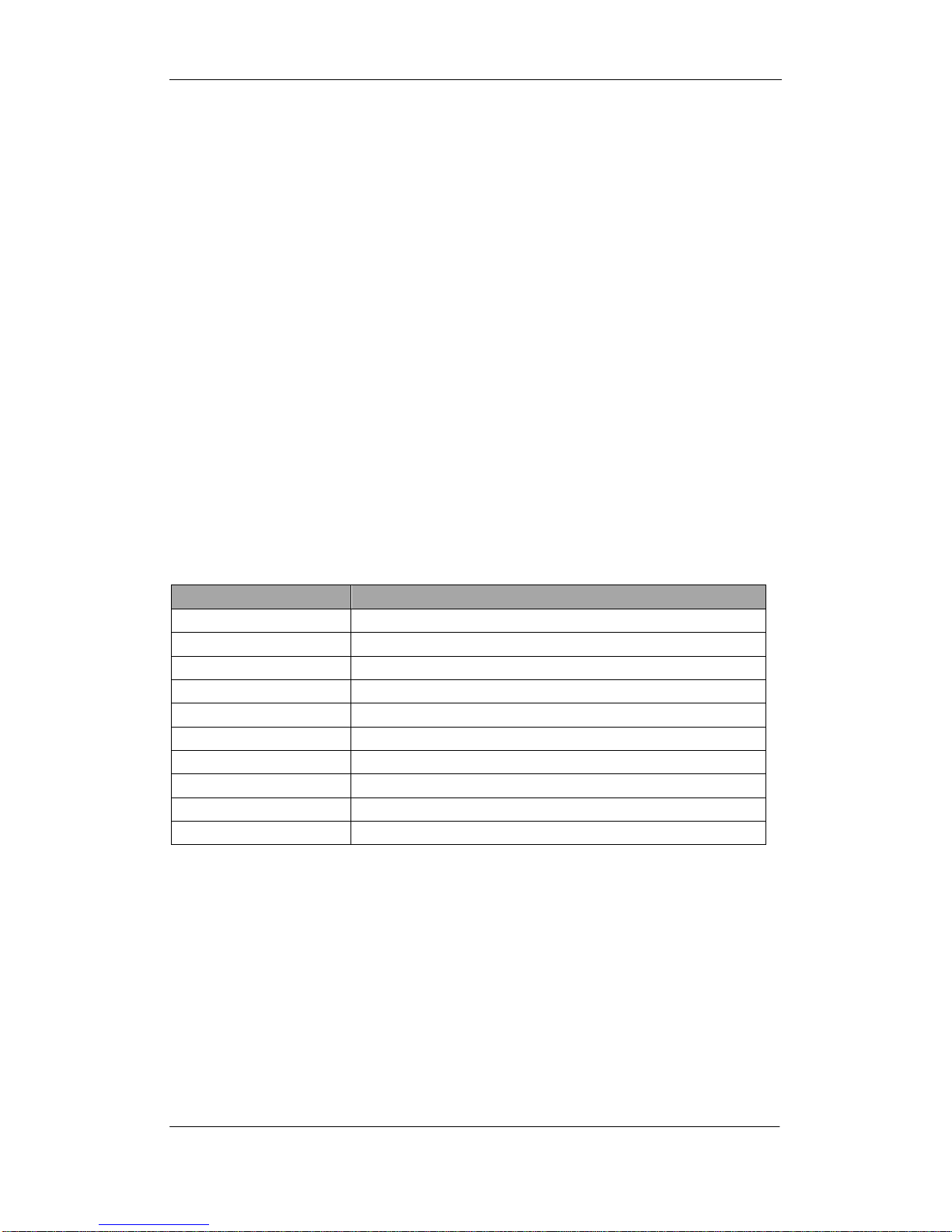
The parameters for different measurement function differ, see table below.
Table 2-1 Measurement parameter
Functions
Parameters
DCV
Range, Integration Time, DC impedance, Auto zero
ACV
Range, AC filiter
DCI
Range, Integration Time, Auto zero
ACI
Range, AC filiter
OHM(2WR、4WR)
Range, Integration Time, Auto zero
CAP
Range
CONT
Short-circuit resistance
DIODE
Breakover voltage
FREQ/PREIOD
Gate time
TEMP
N/A
 Loading...