

SIGLENT SDM3055 User Manual
User Manual
SDM3055 Digital Multimeter
UM06035-E02A
2014 SIGLENT TECHNOLOGIES CO., LTD

SIGLENT
Copyright and Statement
Copyright
SIGLENT TECHNOLOGIES CO., LTD. All rights reserved.
Trademark Information
SIGLENT is registered trademark of SIGLENT TECHNOLOGIES CO., LTD.
Statement
● SIGLENT products are protected by patent laws in and outside of the P.R.
China.
● SIGLENT reserves the rights to change the specification and price.
● Information in this publication replaces all previous corresponding
published material.
● Contents in this manual are not allowed to be copied, extracted or
translated in any form or by any means without SIGLENT’s permission.

SIGLENT
II SDM3055 Digital Multimeter
General Safety Summary
Read the following safety precautions carefully to avoid any personal injuries
or damages to the instrument and any products connected to it. To avoid
potential hazards, please use the instrument as specified.
Use proper power line.
It’s only allowed to use the special power line which is approved by local
state.
Ground the instrument.
The instrument is grounded through the protective terra conductor of the
power line. The ground conductor must be connected to the earth to avoid
electric shock. Make sure the instrument is grounded correctly before
connecting its input or output terminals.
Connect the signal wire correctly
The potential of the signal wire is equal to the earth, so do not connect the
signal wire to a high voltage.
Observe all terminal ratings
Please observe all ratings and sign instructions on the instrument to avoid fire
or electric shock. Before connecting the instrument, please read the manual
carefully to gain more information about the ratings.
Do not operate with suspected failures
If you suspect that the product is damaged, please contact SIGLENT’s
qualified service personnel to inspect it. Any repair and adjustment to the
product or replacing a component should be done by qualified personnel
only.
Avoid circuit or wire exposure
Don’t touch exposed contacts or components when the power is on.
Don’t operate without covers.
Don’t operate the instrument with covers or panels removed.
Use proper fuse.
It’s only allowed to use the specified fuse for the instrument.
Use proper over-voltage protection.
Make sure there is no over-voltage (like voltage caused by thunder and
lightning) reaching to the instrument, otherwise the operator may suffer an
electric shock.

SIGLENT
SDM3055 Digital Multimeter III
Antistatic protection.
Static electricity will cause damages to the instrument, so test in antistatic
areas as far as possible. Ground its inner and outer conductors to release the
static electricity temporarily before connecting the cable to the instrument.
Keep good ventilation.
Improper ventilation will cause the rise of the instrument’s temperature. Keep
good ventilation and check the vent and fan regularly when using it.
Keep the surface of the instrument clean and dry.
Do not operate in wet or damp conditions.
Do not operate in flammable or explosive environment.
The disturbance test of all the models meets the limit values of A in the
standard of EN 61326-1:2013.
Input terminal protection limitation
Protection limitation is defined for the input terminal:
1. Main input(HI and LO)terminal
HI and LO terminals are used for Voltage, Resistance, Capacitance,
Continuity, Frequency and Diode measurement. Two protection limitations
are defined:
HI-LO protection limitation: 1000VDC or 750AVC. It’s the maximum
measurable voltage. The limitation can be expressed as 1000Vpk.
LO-ground protection limitation : LO terminal can “float” 500Vpk
relative to the ground safely. The maximum protection limitation of HI terminal
relative to the ground is 1000Vpk. Therefore, the sum of the “float” voltage
and the measured voltage can’t exceed 1000Vpk.
2. Sampling (HI Sense and LO Sense) terminal
HI Sense and LO Sense are used for 4-wire Resistance measurement. Two
protection limitations are defined:
HI Sense-LO Sense protection limitation: 2000Vpk.
LO Sense-LO Sense protection limitation: 2Vpk.

SIGLENT
IV SDM3055 Digital Multimeter
3. Current input (I) terminal
I and LO terminals are used for current measurement. The maximum
current which go through the I terminal is limited to 10A by the fuse on the
back panel.
NOTE:
Voltage on the current input terminal corresponds to voltage on LO terminal.
To keep good protection, only use the fuse of specified type and level to
replace this fuse.
IEC Measurement Category II Over-voltage Protection
SDM3055 Digital Multimeter provides over-voltage protection for line-voltage
mains connections meeting both of the following conditions to avoid the
danger of electric shock:
The HI and LO input terminals are connected to the mains under
Measurement Category II conditions as following.
The maximum line voltage of the mains is 600VAC.
WARNING:
IEC Measurement Category II includes electrical devices connected to mains
at an outlet on a branch circuit, such as most small appliances, test
equipments, and other devices that plug into a branch outlet or socket.
SDM3055 is capable of making measurements with the HI and LO inputs
connected to mains in such devices (up to 600VAC) or the branch outlet itself.
However, the HI and LO terminals of SDM3055 can’t be connected to mains
in permanently installed electrical devices such as the main circuit-breaker
panels, sub-panel disconnected boxes and permanently wired motors. Such
devices and circuits are prone to exceed the protection limits of SDM3055.
NOTE:
Voltages above 600VAC only can be measured in circuits that are isolated
from mains. However, there may be transient over-voltage in circuits that are
isolated from mains. SDM3055 is able to withstand occasional transient
over-voltage up to 4000Vpk. Please don’t use this instrument to measure
circuits that transient over-voltage may exceed this level.
SIGLENT
SDM3055 Digital Multimeter V
Safety Terms and Symbols
Terms in this manual. Terms may appear in this manual.
Terms used on the instrument. Terms may appear on the instrument:
DANGER indicates an injury or hazard that may immediately happen.
WARNING indicates an injury or hazard that may not immediately happen.
CAUTION indicates that a potential damage to the instrument or other
property might occur.
Symbols used on the instrument. Symbols may appear on the instrument.
WARNING: Warning statements indicate the conditions and
behaviors that could result in injury or loss of life.
CAUTION: Caution statements indicate the conditions and
behaviors that could result in damage to this product or other
CAT I (1000V): IEC Measurement Category I. The highest
measurable voltage is 1000Vpk in the HI-LO terminal.
CAT II (600V): IEC Measurement Category II. Inputs may be
connected to mains (up to 600VAC) under Category II overvoltage
Hazardous
Voltage
Protective Earth
Ground
Warning Test
Ground
Chassis
Ground

SIGLENT
VI SDM3055 Digital Multimeter
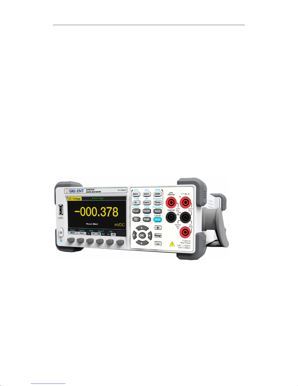
Introduction of SDM3055
SDM3055 is a 5½ dual-display instrument designed with 5½ digits readings
resolution and dual-display, especially fitting to the needs of high-precision,
multifunction, and automation measurements. It realized a combination of
basic measurement functions, multiple math functions, and display functions,
etc.
SDM3055 holds a 4.3 inch color TFT-LCD display screen. Its clear keyboard
layout and operation hints make it easier and agility to use. Besides, it
supports multi-interface such as USB Device & Host, LAN and GPIB (only for
SDM3055A), which can meet users’ demand furthest.
Main Features:
4.3 inch color TFT-LCD display screen with 480*272 high resolutions
Real 5½ digits readings resolution
Up to 150rdgs/S measurement speed
True-RMS AC Voltage and AC Current measurements
1 Gb Nand Flash size, mass storage configuration files and data files
Built-in cold terminal compensation for thermocouple
Support standard SCPI and control software on PC, compatible with
commands of main stream multimeters
Supports dual-display function, Chinese and English menu
Built-in help system, convenient to acquire information
Support USB Device, USB Host, LAN, and GPIB (only for SDM3055A)
interfaces
Configuration and measured data can be imported or exported via VXI 11,
USBTMC and USB flash drive, which is convenient for users to modify,
view and backup

SIGLENT
SDM3055 Digital Multimeter VII
Abstract
The manual mainly introduces corresponding information of operating the
SDM3055 Digital Multimeter. It contains these chapters:
Chapter 1 Quick Start
Guide you to prepare the SDM3055 Digital Multimeter and know about the
Front/Back panel and user interface.
Chapter 2 Function and Operation
Introduce the functions and operations of SDM3055 in details.
Chapter 3 Application Examples
Introduce you how to use strong measurement functions of this instrument
easily through some examples.
Chapter 4 Measurement Tutorial
Guide you to eliminate the errors that may appear during your measurement
and obtain accurate result.
Chapter 5 General Troubleshooting
Provide you some general troubleshooting.
Chapter 6 Appendix
Provide you information about accessories, warranties, troubleshooting,
services and supports.

SIGLENT
VIII SDM3055 Digital Multimeter
Content
Copyright and Statement .............................................................................. II
General Safety Summary............................................................................... II
Safety Terms and Symbols .......................................................................... V
Introduction of SDM3055 ............................................................................. VI
Abstract ....................................................................................................... VII
Content ....................................................................................................... VIII
Chapter 1 Quick Start ................................................................................ 1
General Inspection .................................................................................... 2
To adjust the Handle ................................................................................. 3
Front Panel ............................................................................................... 4
Back Panel ................................................................................................ 5
Power On .................................................................................................. 6
User Interface ........................................................................................... 7
Chapter 2 Function and Operation ........................................................... 8
To Select Measurement Range ................................................................ 9
To Select Measurement Speed .............................................................. 11
Basic Measurement Functions ................................................................ 12
To Measure DC Voltage .................................................................. 13
To Measure DC Current .................................................................. 15
To Measure AC Voltage .................................................................. 17
To Measure AC Current ................................................................... 19
To Measure 2-Wire/4-Wire Resistance ............................................ 21
To Measure Capacitance ................................................................. 25
To Measure Frequency or Period .................................................... 27
To Test Continuity............................................................................ 31
To Test Diode .................................................................................. 33
To Measure Temperature ................................................................ 35
Measurement Parameters ...................................................................... 38
AC Filter ........................................................................................... 38
DC Input Impedance ........................................................................ 39
Short-circuit Resistance ................................................................... 40
Dual-display Function ............................................................................. 41
Utility Function ........................................................................................ 43
Store and Recall .............................................................................. 44
Manage File ..................................................................................... 46
I/O Configuration.............................................................................. 48
Board Test ....................................................................................... 50
Firmware Update ............................................................................. 53
System Setup .................................................................................. 54
Acquire.................................................................................................... 56

SIGLENT
SDM3055 Digital Multimeter IX
Auto Trigger ..................................................................................... 57
Single Trigger .................................................................................. 58
External Trigger ............................................................................... 59
Help System ........................................................................................... 60
Math Function ......................................................................................... 62
Statistics .......................................................................................... 64
Limits ............................................................................................... 66
dBm ................................................................................................. 68
dB .................................................................................................... 69
Relative Value.................................................................................. 70
Display Mode .......................................................................................... 71
Trigger .................................................................................................... 77
Hold Measurement Function ................................................................... 78
Chapter 3 Application Examples ............................................................ 79
Example 1: Reading Statistic Functions.................................................. 80
Example 2: To Eliminate Leads Impedance ............................................ 81
Example 3: dBm Measurement ............................................................... 83
Example 4: dB Measurement .................................................................. 84
Example 5: Limits Test............................................................................ 86
Example 6: Thermocouple setting and measurement ............................. 88
Example 7: To Use Hold Measurement Function ................................... 90
Example 8: To Use Application Software EasySDM ............................... 92
Chapter 4 Measurement Tutorial ............................................................ 93
True RMS AC Measurement ................................................................... 93
Crest Factor Errors (non-sinusoidal inputs) ............................................ 94
Loading Errors (AC Voltage) ................................................................... 95
Application of the Analog Filter ............................................................... 96
Chapter 5 General Troubleshooting....................................................... 97
Chapter 6 Appendix ................................................................................. 98
Appendix A: Accessories ........................................................................ 98
Appendix B: Warranty summary ............................................................. 99
Appendix C: Daily Maintenance and Cleaning ...................................... 100
Appendix D: Contact SIGLENT ............................................................. 101

SIGLENT
SDM3055 Digital Multimeter 1
Chapter 1 Quick Start
General Inspection
Handle Adjustment
The Front Panel
The Back Panel
To Connect Power Line
User Interface
To Use Safety Lock

SIGLENT
2 SDM3055 Digital Multimeter
General Inspection
1. Inspect the shipping container.
Please keep the damaged container or cushioning material until the contents
of the shipment have been checked completely and the instrument has passed
the electrical and mechanical test.
Damages of the instrument caused by the shipment will be compensated by
the shipper or carrier. SIGLENT will not be responsible for the free repair or
replacement.
2. Inspect the instrument.
If there exit any mechanical damages or lacking of components, or the
instrument fails the electrical and mechanical test, please contact your
SIGLENT sales.
3. Check the accessories.
Check the accessories according to the packing list carefully. If there exit any
accessories damaged or missing, please contact your SIGLENT sales.
SIGLENT
SDM3055 Digital Multimeter 3
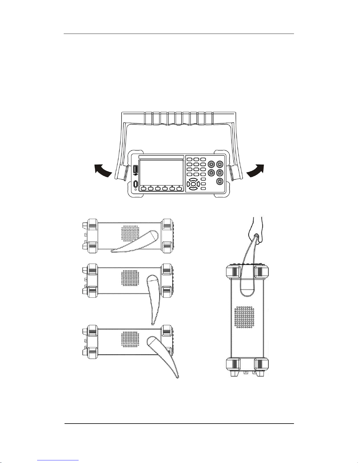
To adjust the Handle
Adjust the handle position of SDM3055 properly to place the instrument stably
so that users can manipulate and observe the display better. Please grip the
handle by the two sides and pull it outward. Then rotate the handle to the
appropriate position. Please operate as the following diagram.
Diagram 1- 1 Handle adjustment
Diagram 1- 2 Horizontal Position Diagram 1- 3 Carrying Position
SIGLENT
4 SDM3055 Digital Multimeter
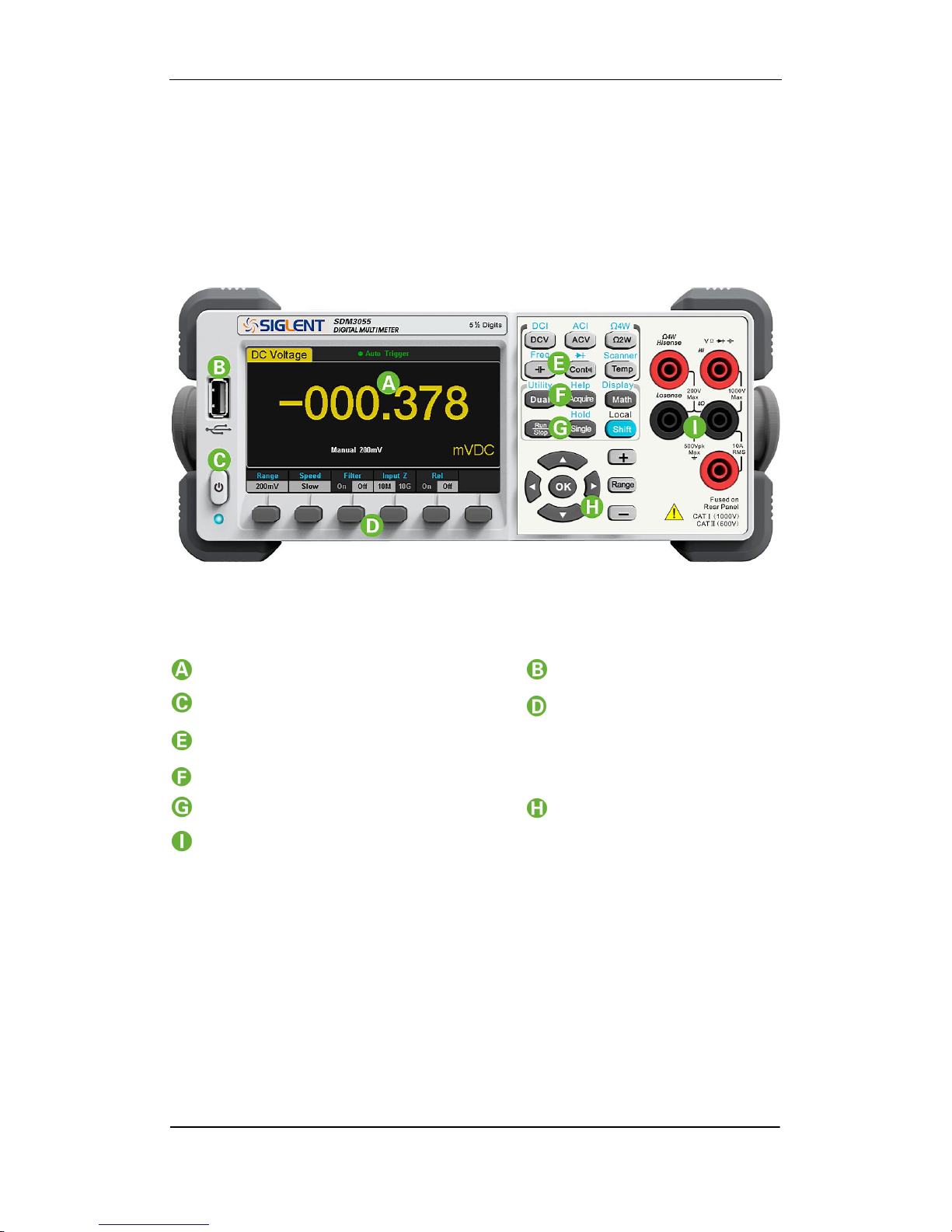
Front Panel
SDM3055 Digital Multimeter provides users with brief and clear front panel.
These control buttons are group by logic and users only need choose
corresponding buttons to carry out basic operations, as shown in Diagram
1-4.
Diagram 1- 4 Front Panel Overview
LCD Display USB Host
Power Key Menu Keys
Basic Measurement Function Keys
Auxiliary Measurement Function Keys
Enable Trig Keys Direction Keys
Signal Input Port
SIGLENT
SDM3055 Digital Multimeter 5
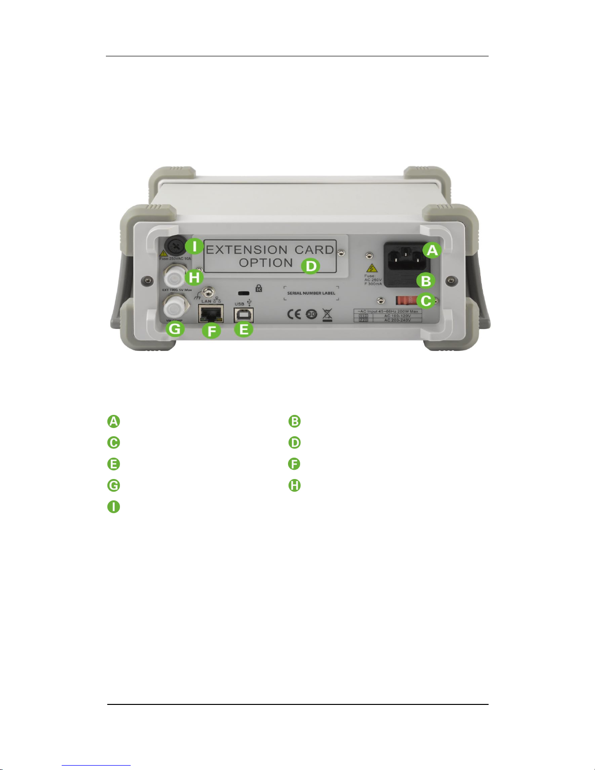
Back Panel
SDM3055 Digital Multimeter’s Back Panel provides users with abundant
interfaces, including USB Device、 USB Host、LAN and GPIB (Only for
SDM3055A), as shown in the following diagram.
Diagram 1- 5 Back Panel Overview
Power Socket Power Fuse
AC Voltage Selector Inspection card interface
USB Device(USBTMC) 10/100 Ethernet
VMC Output Ext Trig
Current Input Fuse
NOTE:
SDM3055 doesn’t support GPIB and Inspection Card;
SDM3055A doesn’t support Inspection Card;
SDM3055S doesn’t support GPIB.

SIGLENT
6 SDM3055 Digital Multimeter
Power On
Please power on the instrument as the following steps:
1. Adjust AC Voltage Selector to 110 (100~120V, 45~440Hz, AC) or 220
(200~240V, 50/60Hz, AC) in accordance with power standards in your
country;
2. Connect the instrument to AC supply via power cord supplied by
SIGLENT;
3. The power indicator light on the front panel will glitter slowly;
4. Press the power key on the front panel, the instrument will be started a few
seconds later.
SIGLENT
SDM3055 Digital Multimeter 7
User Interface
Single Display:
Diagram 1- 6 Single Display Interface
Dual-Display:
Diagram 1-7 User Interface
Main Display
Function
Reading
Display
Measurement Range
Trigger Mode
Unit Softkey Menu
Vice-display
Main
Display
Function
Main
Display
SIGLENT
8 SDM3055 Digital Multimeter
Chapter 2 Function and Operation
To Measure DC Voltage / Current
To Measure AC Voltage / Current
To Measure 2-Wire / 4-Wire Resistance
To Measure Frequency / Capacitance
To Test Continuity / Diode
To Measure Temperature / Optional Multiple Scan Card
To use Dual-display Function or Set Up the Utility
Acquire Function or Help System
Math Function or Display Function
Run / Stop
Single Trigger / Hold Measurement Function
To Switch Functions or Return to Local Menu
To Select Measurement Range

SIGLENT
SDM3055 Digital Multimeter 9
To Select Measurement Range
The Multimeter has two kinds of modes of selecting measurement range:
“Auto” and “Manual”. It can select appropriate range according to the signals
input in Auto mode, which is very convenient for users. While in Manual mode,
you can obtain higher reading precision. Range selection keys are on the right
side of the front panel as the following diagram.
To increase range
To decrease range
Diagram 2- 1 Range Selection Keys
Method 1: By Function keys on the Front Panel
Auto Range: Press to switch between Auto Range and Manual Range.
Manual Range: Press to increase range and press to decrease
range.
Method 2: By softkeys on the measurement main interface as Diagram 2-2.
Auto Range: Press【Auto】to choose Auto Range, meanwhile Manual Range is
forbidden.
Manual Range: Press【200mV】、【2V】、【20V】、【200V】or【1000V】
to choose required range manually. Auto Range is forbidden at this moment.
To switch modes
SIGLENT
10 SDM3055 Digital Multimeter
Diagram 2- 2 Range selection menus
Explanations:
1. When the input signal is beyond the current scope of the measurement
range, the Multimeter will show “overload”.
2. Range option will turn back to default setting “Auto” after restarting and
remote reset.
3. Users are suggested to select “Auto” range so as to protect the instrument
against damage and get exact data as much as possible when it’s hard to
predict the range of measurement.
4. For Dual-display Function, the measurement ranges of Main display and
vice display are similar and can’t be changed independently
5. The range is fixed during testing the Continuity and Diode. The range of
continuity is selected as 2kΩ, while the Diode is 2V.
6. Auto Range is not suitable for measuring current up to 10A. If the signal is
used to I Terminal, users need to choose range manually.

SIGLENT
SDM3055 Digital Multimeter 11
To Select Measurement Speed
The instrument provides three types of measurement rate: 5 reading/s, 50
reading/s and 150 reading/s. 5 reading/s belongs to “Slow” rate; 50 reading/s
belongs to “Middle” rate; 150 reading/s belongs to “Fast” rate.
Measurement speed can be controlled by softkey menu. Press 【Speed】 and
then press 【Slow】,【Middle】or【Fast】to choose measurement speed.
Diagram 2- 3 Range selection menu
Explanations:
1. Three reading rates are available for DCV, ACV, DCI, ACI and 2-Wire/
4-Wire Resistance: “Slow”, “Middle” and “Fast”.
2. There is a linkage for both reading resolution and reading (measurement)
rate.
3. 5 reading/s belongs to 5.5 digit resolution.
4. Both 20 reading/s and 123 reading/s belong to 4.5 digit resolution.
5. The reading resolution of Temperature is fixed at 5.5 digit and “Slow”
respectively.
6. The reading resolutions and measurement rates of both Diode and
Continuity are fixed at 4.5 digit and “Fast” respectively.
7. The reading resolution and measurement rate of the Frequency function
are fixed 5.5 digit and “Slow” respectively.
8. The reading resolution and measurement rate of the Capacitance function
are fixed at 5.5 digit and “Slow” respectively.

SIGLENT
12 SDM3055 Digital Multimeter
Basic Measurement Functions
SDM3055 Digital Multimeters have following basic functions:
To Measure DC Voltage
To Measure AC Voltage
To Measure DC Current
To Measure AC Current
To Measure 2/4-Wire Resistance
To Measure Capacitance
To Test Continuity
To Test Diode
To Measure Frequency or Period
To Measure Temperature
SIGLENT
SDM3055 Digital Multimeter 13
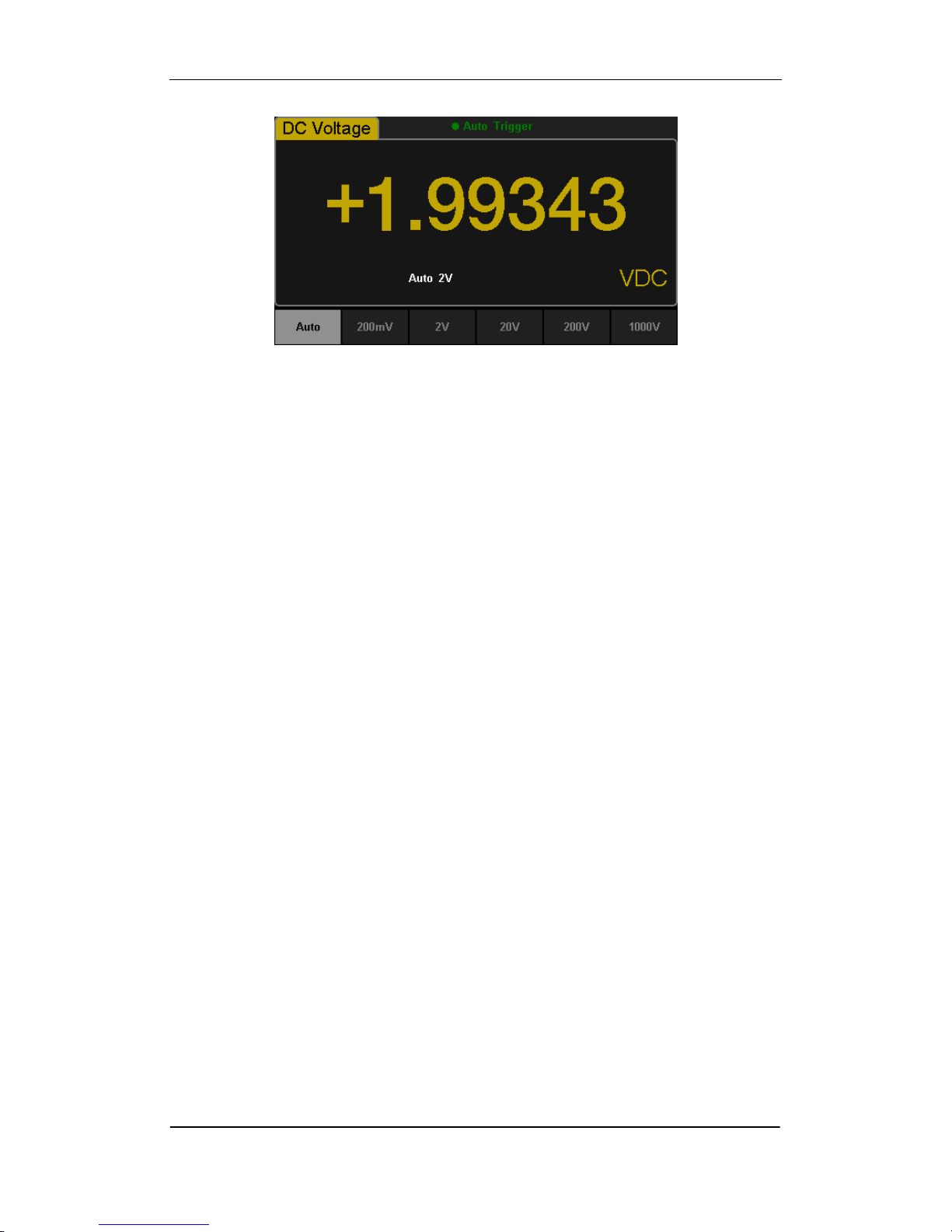
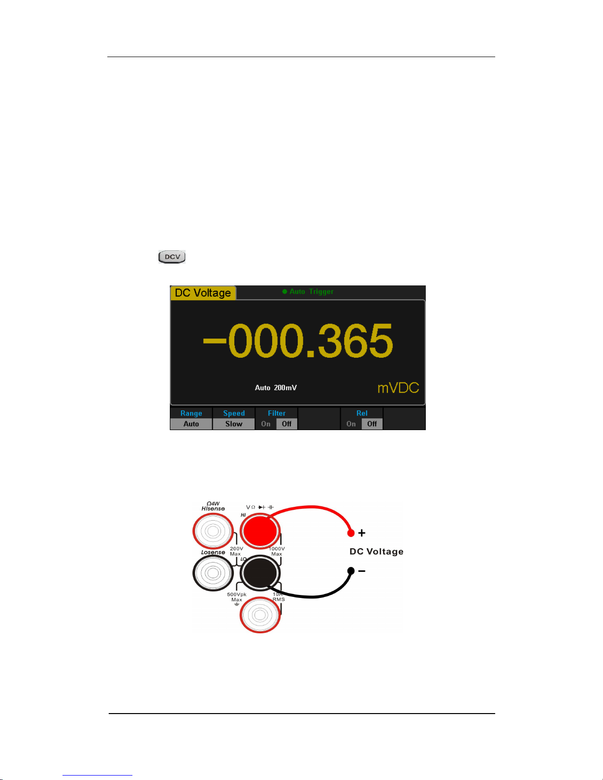
To Measure DC Voltage
The Multimeter enables to measure DC Voltage up to 1000V. The method to
connect and measure DC Voltage will be introduced in details as the following
steps. (NOTE: DC Voltage is always the selected function when the
Multimeter is turned on)
Operating Steps:
1. Press on the front panel to enter the DC Voltage measurement
interface, as shown in Diagram 2- 4.
Diagram 2- 4 DC Voltage Measurement Interface
2. Connect the red lead to terminal Input-HI and black lead to terminal
Input-LO as the following diagram.
Diagram 2- 5 Sketch Map for Measuring DC Voltage

SIGLENT
14 SDM3055 Digital Multimeter
3. Choose a proper voltage range according to the measured circuit.
Table 2- 1 Measurement Characteristics of DC Voltage
Ranges*
200mV、2V、20V、200V、1000V
Input Protection
1000V on all ranges(HI terminal)
Configurable
Range, DC input impedance, Rel
NOTE*:
All the ranges enable to obtain 20% value higher than original except
1000V. Besides, both Manual and Auto are available for setting every
range.
When inputting range is higher than 1000V at 1000V Level, “overload” will
be shown on the screen.
1000V input protection exists in every range.
4. Set the DC input impedance (Only for Manual 200mV and 2V ranges).
Press 【Input Z】to set the DC resistance as “10M” (default value) or
“>10G”. Users can execute DC voltage measurement directly without
modifying this parameter which has been setup before leaving factory.
5. Set AC Filter function.
Press 【Filter】to open or close the AC Filter. (NOTE: Only DC Voltage and
DC Current have this function.)
6. Set relative value (Optional operation).
Press 【Rel】to open or close Relative math function. When it is opened, the
reading displayed is a relative value which comes from the result of actual
measurement value subtracts the value that has been set. (Please refer to
“ Math Functions” in Chapter 2 to know about the details.)
7. Read measurement result.
Select required measurement rate (reading rate) by pressing 【Speed】
and read the measurement result.
8. View history data.
There are four types of way to view historical data: “Number”, “Bar
Meter” ”Trend Chart” and “Histogram”.
SIGLENT
SDM3055 Digital Multimeter 15
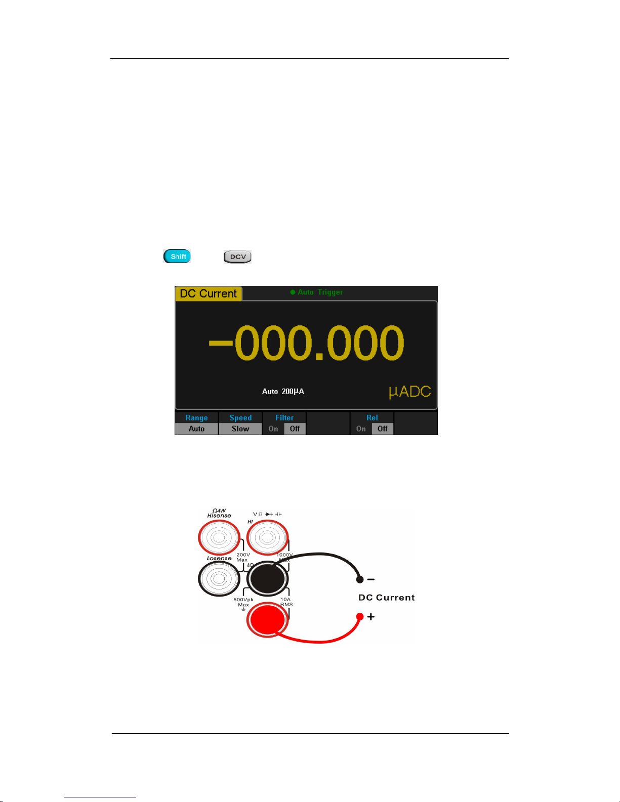
To Measure DC Current
The Multimeter enables to measure DC Current up to 10A. The method to
connect and measure DC Current will be introduced in details as the following
steps.
Operating Steps:
1. Press and on the front panel to enter the DC Current
measurement interface, as shown in Diagram 2- 6.
Diagram 2- 6 DC Voltage Measurement Interface
2. Connect the red lead to terminal Input-I and black lead to terminal
Input-LO as the following diagram.
Diagram 2- 7 Sketch Map for Measuring DC Current

SIGLENT
16 SDM3055 Digital Multimeter
3. Choose a proper current range according to the measured circuit.
Table 2- 2 Measurement Characteristics of DC Current
Ranges*
200μA、2mA、20mA、200mA、2A、10A
Input Protection 10A(back panel), 20A(inside the instrument)
Configurable
Range, Rel
NOTE*:
All the ranges enable to obtain 20% value higher than original except 10A.
Besides, both Manual and Auto are available for setting every range.
4. Set AC Filter function.
Press 【Filter】to open or close the AC Filter.
5. Set relative value (Optional operation).
Press 【Rel】to open or close Relative math function. When it is opened, the
reading displayed is a relative value which comes from the result of actual
measurement value subtracts the value that has been set. (Please refer to
“ Math Functions” in Chapter 2 to know about the details.)
6. Read measurement result.
Select required measurement rate (reading rate) by pressing【Speed】and
read the measurement result.
7. View history data.
There are four types of way to view historical data: “Number”, “Bar
Meter” ”Trend Chart” and “Histogram”.
SIGLENT
SDM3055 Digital Multimeter 17
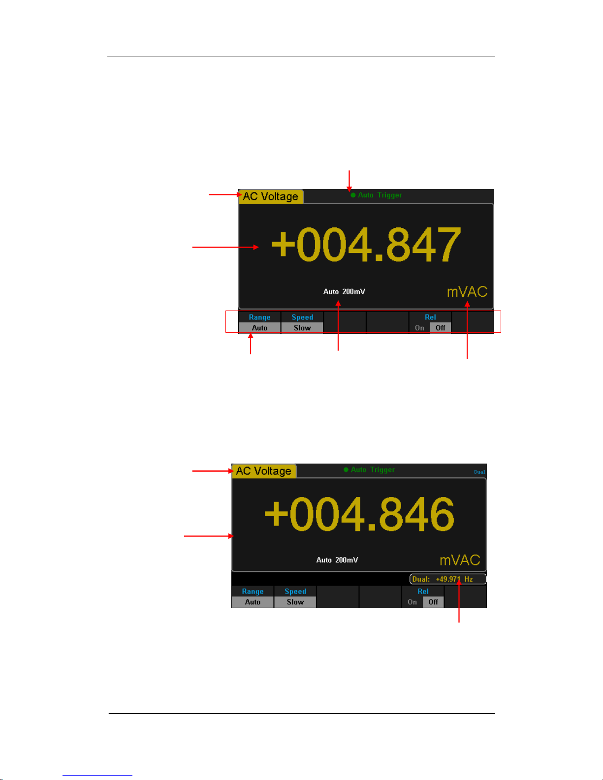
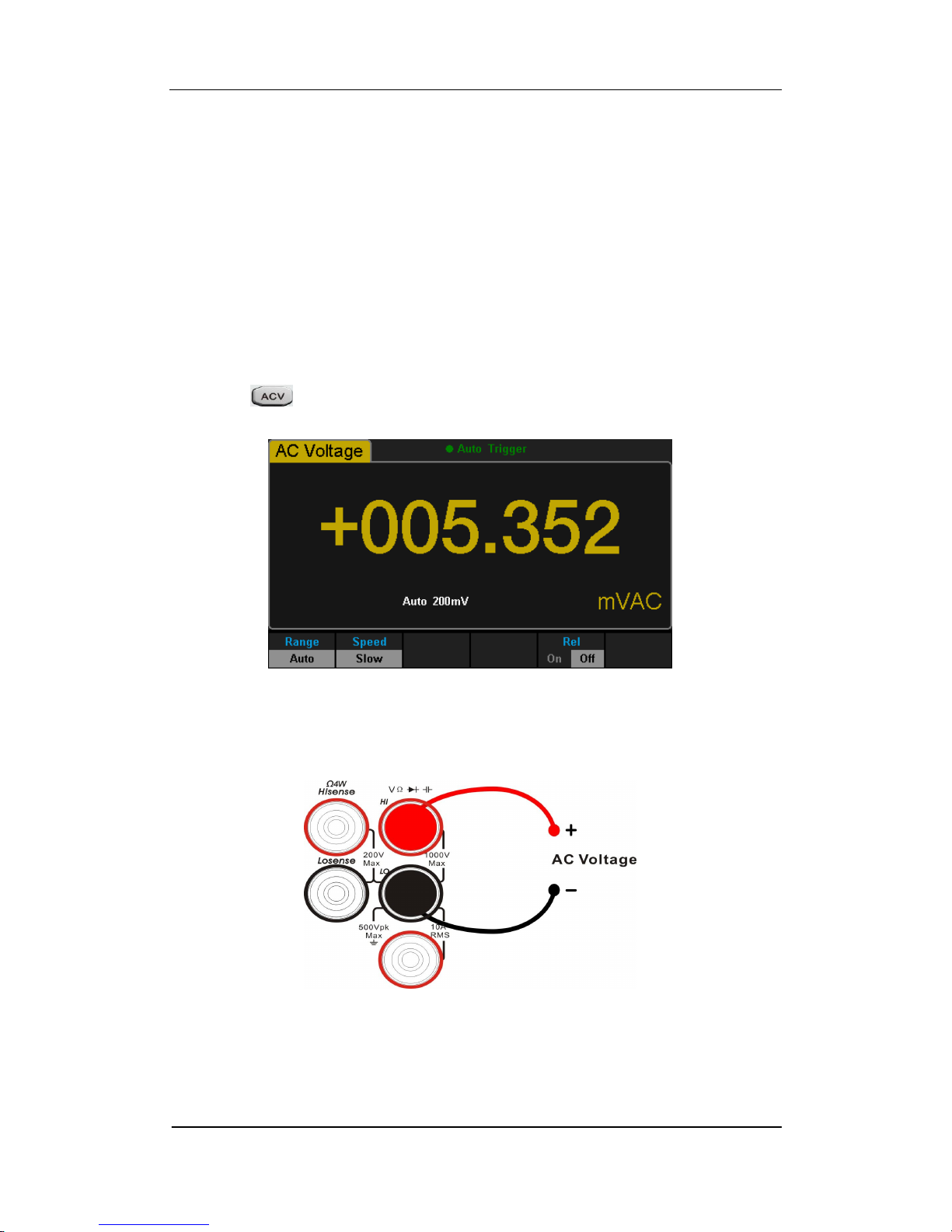
To Measure AC Voltage
The Multimeter enables to measure AC Voltage up to 750V. The method to
connect and measure DC Voltage will be introduced in details as the following
steps.
Operating Steps:
1. Press on the front panel to enter the AC Voltage measurement
interface, as shown in Diagram 2- 8.
Diagram 2- 8 AC Voltage Measurement Interface
2. Connect the red lead to terminal Input-HI and black lead to terminal
Input-LO as the following diagram.
Diagram 2- 9 Sketch Map for Measuring AC Voltage
SIGLENT
18 SDM3055 Digital Multimeter
3. Choose a proper voltage range according to the measured circuit.
Table 2- 3 Measurement Characteristics of AC Voltage
Ranges*
200mV、2V、20V、200V、750V
Input Protection
750Vrms on all ranges(HI terminal)
Configurable
Range, Rel
NOTE*:
All the ranges enable to obtain 20% value higher than original except
750V. Besides, both Manual and Auto are available for setting every
range.
When inputting range is higher than 750V at 750V Level, “overload” will be
shown on the screen.
750V input protection exists in every range.
4. Set relative value (Optional operation).
Press【Rel】to open or close Relative math function. When it is opened, the
reading displayed is a relative value which comes from the result of actual
measurement value subtracts the value that has been set. (Please refer to
“ Math Functions” in Chapter 2 to know about the details.)
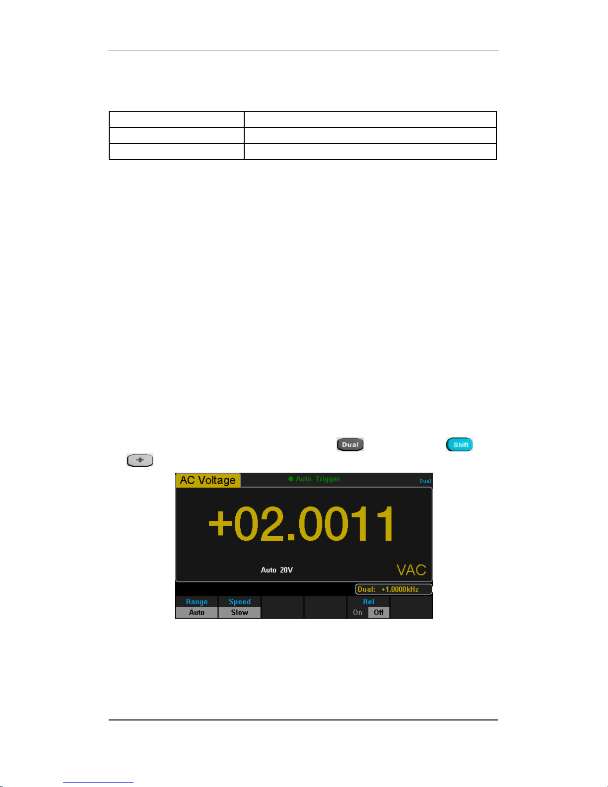
5. Read measurement result.
Select required measurement rate (reading rate) by pressing 【Speed】and
read the measurement result. If you press and then press and
to get the frequency value measured from input AC signal.
Diagram 2- 10 Dual-display
6. View history data.
There are four types of way to view historical data: “Number”, “Bar
Meter” ”Trend Chart” and “Histogram”.
SIGLENT
SDM3055 Digital Multimeter 19
To Measure AC Current
The Multimeter enables to measure AC Current up to 10A. The method to
connect and measure AC Current will be introduced in details as the following
steps.
Operating Steps:
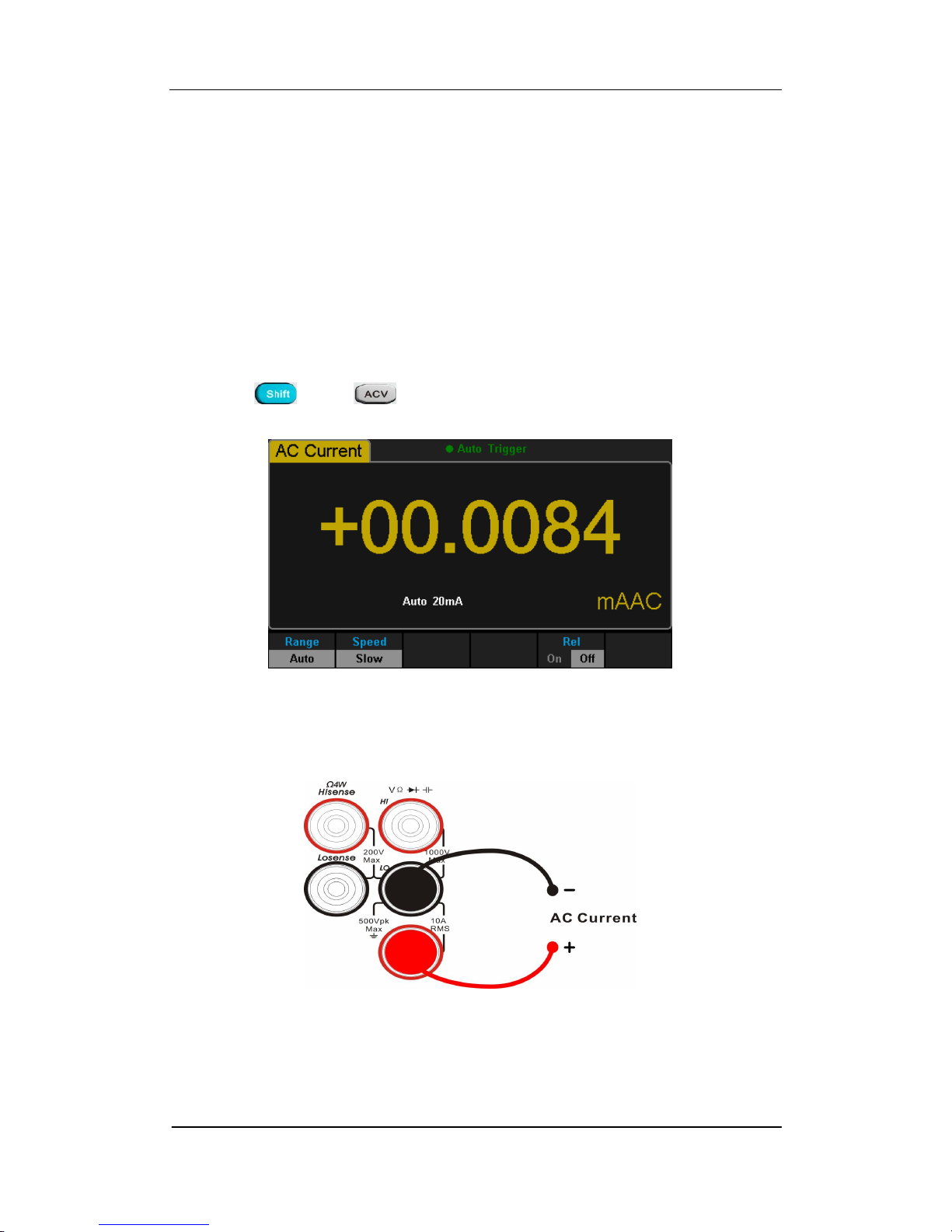
1. Press and on the front panel to enter the AC Current
measurement interface, as shown in Diagram 2- 11.
Diagram 2- 11 AC Voltage Measurement Interface
2. Connect the red lead to terminal Input-I and black lead to terminal
Input-LO as the following diagram.
Diagram 2- 12 Sketch Map for Measuring AC Current

SIGLENT
20 SDM3055 Digital Multimeter
3. Choose a proper current range according to the measured circuit.
Table 2- 4 Measurement Characteristics of AC Current
Ranges*
200μA、2mA、20mA、200mA、2A、10A
Input Protection
10A(back panel), 250V(fuse), 20A(inside the
instrument)
Configurable
Range, Rel
NOTE*:
All the ranges enable to obtain 20% value higher than original except 10A.
Besides, both Manual and Auto are available for setting every range.
4. Set relative value (Optional operation).
Press 【Rel】to open or close Relative math function. When it is opened, the
reading displayed is a relative value which comes from the result of actual
measurement value subtracts the value that has been set. (Please refer to
“ Math Functions” in Chapter 2 to know about the details.)
5. Read measurement result.
Select required measurement rate (reading rate) by pressing 【Speed】
and read the measurement result.
6. View history data.
There are four types of way to view historical data: “Number”, “Bar
Meter” ”Trend Chart” and “Histogram”.
 Loading...