

SIGLENT SDM3065X, SDM3045X Service Manual

SDM3065X
Digital Multimeter
Service Manual
SM06036-E02E
SDM3065X Service Manual I

Guaranty and Declaration
Copyright
SIGLENT TECHNOLOGIES CO., LTD All Rights Reserved.
Trademark Information
SIGLENT is the registered trademark of SIGLENT TECHNOLOGIES CO.,
LTD
Declaration
SIGLENT products are protected by patent law in and outside of the P.R.C.
SIGLENT reserves the right to modify or change parts of or all the
specifications or pricing policies at company’s sole decision.
Information in this publication replaces all previously corresponding
material.
Any way of copying, extracting or translating the contents of this manual is
not allowed without the permission of SIGLENT.
SIGLENT will not be responsible for losses caused by either incidental or
consequential in connection with the furnishing, use or performance of this
manual as well as any information contained.
Product Certification
SIGLENT guarantees this product conforms to the national and industrial
standards in China as well as the ISO9001: 2008 standard and the ISO14001:
2004 standard. Other international standard conformance certification is in
progress.

General Safety Summary
Review the following safety precautions to avoid personal injuries and prevent
damages to this product or any products connected to it. To avoid potential
hazards, use this product only as specified.
Only qualified personnel should perform service procedures.
To Avoid Fire or Personal Injuries
Use Proper Power Cord. Use only the power cord specified for this product
and approved by the local regulating body.
Avoid Electric Shock. To avoid injuries or losses of life, do not connect or
disconnect probes or test leads while they are connected to a voltage source.
Ground the Product. This product is grounded through the protective terra
conductor of the power line. To avoid electric shock, the grounding conductor
must be connected to the earth. Make sure the instrument is grounded
correctly before connecting its input or output terminals.
Connect the Probe Properly. Do not connect the probe ground lead to a high
voltage since it has the isobaric electric potential as ground.
Observe All Terminal Ratings. To avoid fire or shock hazard, observe all
ratings and markers on the instrument and check your manual for more
information about ratings before connecting.
Use Proper Fuse. Use only the specified fuse.
Do Not Operate Without Covers. Do not operate this instrument with covers
or panels removed.
SDM3065X Service Manual III

Avoid Circuit or Wire Exposed. Do not touch exposed junctions and
components when the unit is powered.
Do Not Operate With Suspected Failures. If you suspect damage has
occurred to this instrument, have it inspected by qualified service personnel
before any further operation. Any maintenance, adjustment or replacement
especially to the circuits or accessories should be performed by SIGLENT
authorized personnel.
Keep Product Surfaces Clean and Dry.
Do Not Operate in Wet/Damp Conditions. To avoid electric shock, do not
operate the instrument in wet or damp conditions.
Do Not Operate in an Explosive Atmosphere. To avoid injuries or fire
hazards, do not operate in an explosive atmosphere.
Safety Terms and Symbols
Terms on the Product. These terms may appear on the product:
DANGER: Indicates an injury or hazard that may immediately happen.
WARNING: Indicates that there is potential for an injury or hazard.
CAUTION: Indicates damage to the instrument or other property may occur.
Symbols on the Product. These symbols may appear on the product:

Catalog
Guaranty and Declaration ............................................................................................................. II
General Safety Summary ............................................................................................................. III
General Features and Specifications .......................................................................................... 1
General Features.................................................................................................................... 1
Specifications .......................................................................................................................... 2
Prepare Information ..................................................................................................................... 10
Functional check ................................................................................................................... 10
Power-on Inspection .................................................................................................... 10
Default Setup ................................................................................................................ 10
Self Test ......................................................................................................................... 11
Performance Verification ............................................................................................................. 12
Performance verification test items ................................................................................... 12
Recommended Test Equipment ......................................................................................... 12
Performance verification step ............................................................................................. 12
Test Considerations.............................................................................................................. 13
Zero Offset Verification ........................................................................................................ 13
DC Voltage and DC Current Gain Verification ................................................................. 14
Frequency Accuracy Verification ........................................................................................ 15
AC Voltage and AC Current Verification ............................................................................ 15
Capacitance Verification ...................................................................................................... 16
Calibration Adjusting Procedures .............................................................................................. 17
Calibration Adjustment Interval........................................................................................... 17
Calibration is Recommended ............................................................................................. 17
Automating Calibration Procedures ................................................................................... 17
Calibration Adjustment items .............................................................................................. 17
Recommended Test Equipment ......................................................................................... 18
Software Environment ......................................................................................................... 18
Test Considerations.............................................................................................................. 19
Calibration Adjustment step ................................................................................................ 19
Assembly Procedures .................................................................................................................. 23
Security Consideration ........................................................................................................ 23
Required Tools ...................................................................................................................... 23
Disassembly Procedures .................................................................................................... 25
Troubleshooting ............................................................................................................................ 24
ESD Precautions .................................................................................................................. 29
Required Equipments .......................................................................................................... 29
Analog Board Drawing ......................................................................................................... 30
Main Board Drawing ............................................................................................................ 31
Check the Power Supply ..................................................................................................... 32
Check the Analog Board ...................................................................................................... 33
Voltage Check ............................................................................................................... 33
SDM3065X Service Manual V

Analog board Clock Check ......................................................................................... 34
Check the Main Board ......................................................................................................... 34
Voltage Check ............................................................................................................... 34
Microprocessor Check ................................................................................................. 35
Quick Guide for General Failures ...................................................................................... 35
Maintenance .................................................................................................................................. 36
Maintenance Summary ........................................................................................................ 36
Repackaging for Shipment .................................................................................................. 36
Contact SIGLENT ......................................................................................................................... 37

General Features and Specifications
SDM3065X is a multimeter designed with 6½ digit reading resolution and
dual-display suited for any application requiring high-precision, multifunction,
and automated measurements. It features a combination of basic
measurement, multiple math, and display functions, etc.
General Features
4.3 inch color TFT-LCD display screen with 480*272 high resolution
Real 6½ digit reading resolution
Up to 150 rdgs/s measurement speed
True-RMS AC Voltage and AC Current measurements
1 Gb Nand Flash size, mass storage configuration and data files
Built-in cold terminal compensation for accurate thermocouple readings
Supports standard SCPI includes EasyDMM PC software for easy control
and data collection
Supports dual-display function, Chinese and English menu
Built-in help system, convenient to acquire information
Supports standard communications buses: USB Device, USB Host, LAN
(Optional Accessories: USB-GPIB adapter)
SDM3065X-SC supports 12 voltage/4 current channel Scanner Card
SDM3065X Service Manual 1
Specifications
Function
Range
[2]
Test
Current
Or
Burden
Voltage
24Hour
[3]
TCAL℃ ±1℃
90day
TCAL℃ ±5℃
1Year
TCAL℃ ±5℃
Temperature
coefficient
0℃to ( TCAL℃-5℃ )
(TCAL℃+5℃)to 50℃
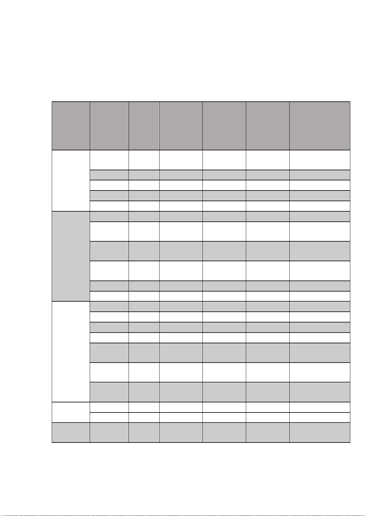
DC Voltage
200.0000
mV
0.0020+ 0.0015
0.0030 + 0.0020
0.0040 + 0.0023
0.0005 + 0.0003
2.000000 V
0.0015 + 0.0004
0.0020 + 0.0004
0.0035 + 0.0006
0.0005 + 0.0001
20.00000 V
0.0020 + 0.0003
0.0030 + 0.0004
0.0040 + 0.0004
0.0005 + 0.0001
200.0000 V
0.0020 + 0.0005
0.0040 + 0.0004
0.0050 + 0.0005
0.0005 + 0.0001
1000.000 V
[4]
0.0020 + 0.0005
0.0040 + 0.0008
0.0055 + 0.0008
0.0005 + 0.0001
DC Current
200.0000 μA
< 0.03 V
0.009 + 0.010
0.040 + 0.005
0.050 + 0.005
0.0020 + 0.0026
2.000000
mA
< 0.25 V
0.007 + 0.001
0.030 + 0.001
0.050 + 0.002
0.0020 + 0.0001
20.00000
mA
< 0.07 V
0.006 + 0.008
0.030 + 0.005
0.050 + 0.005
0.0020 + 0.0015
200.0000
mA
< 0.7 V
0.009 + 0.001
0.030 + 0.001
0.050 + 0.002
0.0020 + 0.0001
2.000000 A
< 0.12 V
0.045 + 0.015
0.080 + 0.005
0.100 + 0.012
0.0050 + 0.0008
10.00000 A
[5]
< 0.6 V
0.090 + 0.002
0.120 + 0.005
0.150 + 0.005
0.0050 + 0.0018
Resistance
[6]
200.0000 Ω
1 mA
0.0030 + 0.0031
0.008 + 0.005
0.010 + 0.004
0.0006 + 0.0006
2.000000 kΩ
1 mA
0.0020 + 0.0005
0.008 + 0.001
0.010 + 0.001
0.0006 + 0.0001
20.00000 kΩ
100 μA
0.0020 + 0.0005
0.008 + 0.001
0.010 + 0.001
0.0006 + 0.0001
200.0000 kΩ
10 μA
0.0020 + 0.0005
0.008 + 0.001
0.010 + 0.001
0.0006 + 0.0001
1.000000
MΩ
2 μA
0.0020+ 0.0010
0.010 + 0.001
0.012 + 0.001
0.0010 + 0.0002
10.00000
MΩ
200 nA
0.015 + 0.001
0.030 + 0.001
0.040 + 0.001
0.0030 + 0.0005
100.0000
MΩ
200 nA ||
10 MΩ
0.300 + 0.010
0.800 + 0.010
0.800 + 0.010
0.1500 + 0.0002
Diode Test
[7]
0~2 V
1 mA
0.002 + 0.009
0.008 + 0.020
0.010 + 0.020
0.0010 + 0.0020
2~4 V
1 mA
0.002 + 0.010
0.008 + 0.020
0.010 + 0.020
0.0010 + 0.0020
Continuity
Test
2000.0 Ω
1 mA
0.002 + 0.010
0.008 + 0.020
0.010 + 0.020
0.0010 + 0.0020
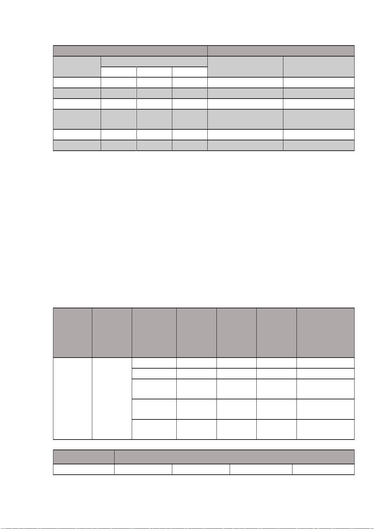
DC Characteristics
Accuracy ± (% of reading + % of range)
[1]
Remarks:
[1] Specifications are for 90-minute warm-up and 100 NPLC integration time. For integration time
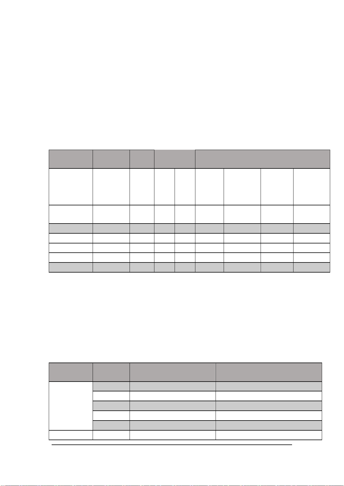
<100NPLC, add the appropriate “RMS Noise Adder” listed in the following table.
Integration Time
Resolution
[1]
NMRR
[2]
Readings/s
[3]
RMS Noise Adder
[4]
(% of Range)
Number of
Power line
Cycles
[5]
(NPLC)
(ppm Range)
(dB)
50 Hz
60 Hz
DCV 20 V
DCV 2 V 200
V
Resistance
2 kΩ 20 kΩ
DCV 1000 V
DCI 2 mA
200 mA
DCV 200 mV
Resistance
200 Ω
DCI 10 A
0.005(0.006)
2.7
0
1000
0
1000
0
0.0006
0.0008
0.0015
0.0040
0.05 (0.06)
1.6
0
1000
1000
0.0004
0.0005
0.0008
0.0025
0.5 (0.6)
1
0
100
100
0.0003
0.0003
0.0006
0.0025
1
0.22
60
50
60 0 0.0001
0.0002
0.0005
10
0.08
60
5 6 0 0 0
0.0002
100
0.035
60
0.5
0.6 0 0 0 0
Function
Range
Spurious-Free
Dynamic Range (SFDR)
Signal-to-Noise-and-Distortion
(SINAD)
DCV
200 mV
80
75
2 V
76
80
20 V
78
72
200 V
80
78
1000 V
82
80
DCI
200 uA
90
70
[2] 10% over range on all ranges except DCV 1000 V and DCI 10 A range.
[3] Relative to calibration standards.
[4] For each additional volt over ± 500 V, add 0.03 mV error.
[5] For continuous current > 7A DC or 7A AC RMS, 30 seconds ON and 30 seconds OFF.
[6] Specifications are for 4–wire resistance measurement or 2–wire resistance measurement using REL
operation. Without REL operation, add 0.2 Ω additional error in 2-wire resistance measurement.
[7] Accuracy specifications for the voltage measured at the input terminal only. 1 mA test current is typical.
Variation in the current source will create some variation in the voltage drop across a diode junction.
Adjustable voltage range :0~4 V.
Performance Versus Integration Time – 50 Hz (60 Hz) Power-line Frequency
Remarks:
[1] Typical value. Resolution is defined as the typical 20 V range RMS noise.
[2] Normal mode rejection ratio for power-line frequency ± 0.1%. For power-line frequency ± 1%, subtract
20 dB. For ± 3%, subtract 30 dB.
[3] Maximum rate for DCV, DCI, 2-wire resistance and 4-wire resistance functions.
[4] The basic DC accuracy specifications include RMS noise at 100 NPLC. For <100 NPLC, add “RMS
Noise Adder” to the basic DC accuracy specifications.
[5] When Power Supply of frequency is 60 Hz, the cycles is 0.006, 0.06, 0.6,1,10,100 NPLC.
SFDR & SINAD
[1]
SDM3065X Service Manual 3
2 mA
90
80
20 mA
85
70
200 mA
80
75
2 A
70
60
[1] Typical value. -1 dBFS, 1 kHz single tone. 100 us aperture time and auto zero off.
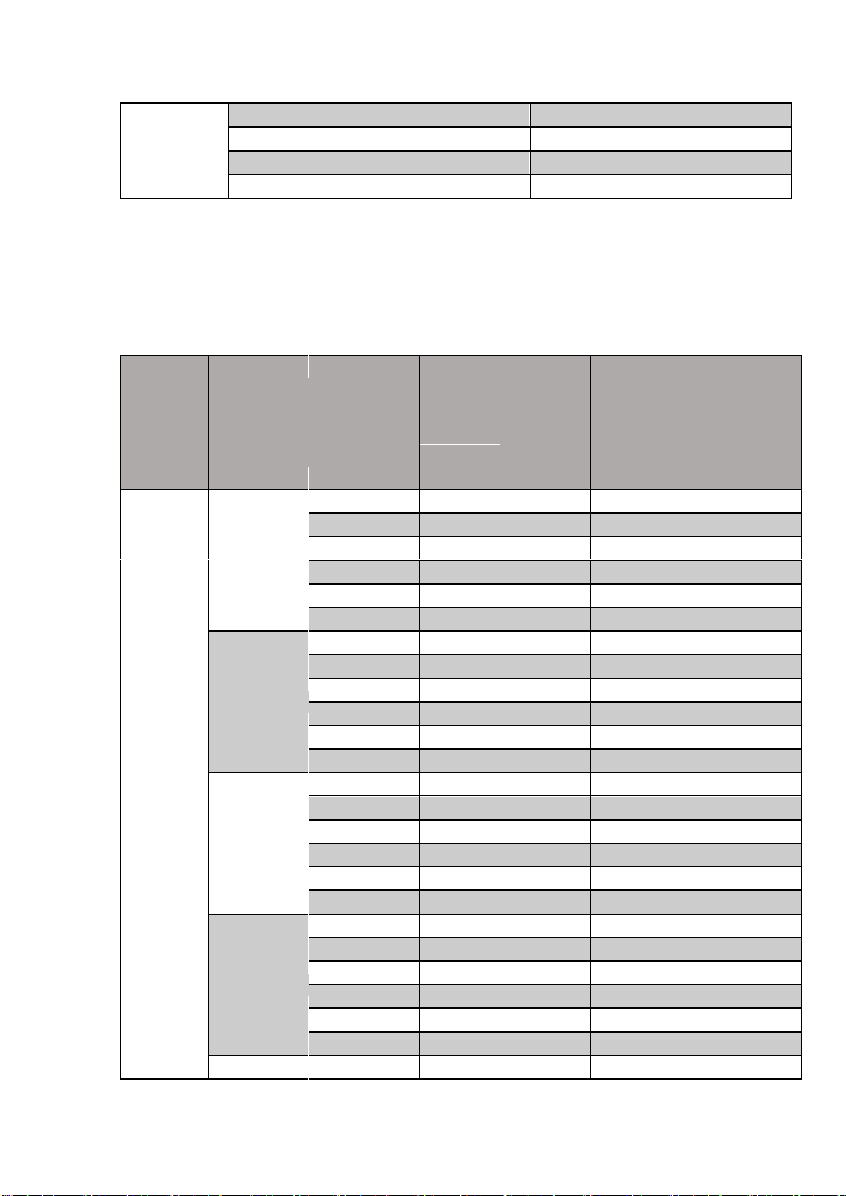
Function
Range
[2]
Frequency
Range
24
Hour
[3]
TCAL℃
±1℃
90 Day
TCAL℃ ±5℃
1 Year
TCAL℃ ±5℃
Temperature
coefficient
0℃ to
( TCAL℃-5℃ )
( TCAL℃+5℃ )to
50℃
True-RMS
AC
Voltage
[4]
200.0000 mV
3 Hz- 5 Hz
1.00 + 0.03
1.00 + 0.04
1.00 + 0.04
0.100 + 0.004
5 Hz-10 Hz
0.35 + 0.03
0.35 + 0.04
0.35 + 0.04
0.035 + 0.005
10 Hz-20 kHz
0.04 + 0.03
0.05 + 0.04
0.06 + 0.04
0.005 + 0.004
20 kHz-50 kHz
0.10 + 0.05
0.11 + 0.05
0.12 + 0.05
0.011 + 0.005
50 kHz-100 kHz
0.55 + 0.08
0.60 + 0.08
0.60 + 0.08
0.060 + 0.008
100 kHz- 300 kHz
4.00 + 0.50
4.00 + 0.50
4.00 + 0.50
0.20 + 0.02
2.000000 V
3 Hz- 5 Hz
1.00 + 0.02
1.00 + 0.03
1.00 + 0.03
0.100 + 0.003
5 Hz-10 Hz
0.35 + 0.02
0.35 + 0.03
0.35 + 0.03
0.035 + 0.003
10 Hz-20 kHz
0.04 + 0.02
0.05 + 0.03
0.06 + 0.03
0.005 + 0.003
20 kHz-50 kHz
0.10 + 0.04
0.11 + 0.05
0.12 + 0.05
0.011 + 0.005
50 kHz-100 kHz
0.55 + 0.08
0.60 + 0.08
0.60 + 0.08
0.060 + 0.008
100 kHz- 300 kHz
4.00 + 0.50
4.00 + 0.50
4.00 + 0.50
0.20 + 0.02
20.00000 V
3 Hz- 5 Hz
1.00 + 0.03
1.00 + 0.04
1.00 + 0.04
0.100 + 0.004
5 Hz-10 Hz
0.35 + 0.03
0.35 + 0.04
0.35 + 0.04
0.035 + 0.004
10 Hz-20 kHz
0.04 + 0.04
0.07 + 0.04
0.08 + 0.04
0.008 + 0.004
20 kHz-50 kHz
0.10 + 0.05
0.12+ 0.05
0.15 + 0.05
0.012 + 0.005
50 kHz-100 kHz
0.55 + 0.08
0.60 + 0.08
0.60 + 0.08
0.060 + 0.008
100 kHz- 300 kHz
4.00 + 0.50
4.00 + 0.50
4.00 + 0.50
0.20 + 0.02
200.0000 V
3 Hz- 5 Hz
1.00 + 0.02
1.00 + 0.03
1.00 + 0.03
0.100 + 0.003
5 Hz-10 Hz
0.35 + 0.02
0.35 + 0.03
0.35 + 0.03
0.035 + 0.003
10 Hz-20 kHz
0.04 + 0.02
0.07 + 0.03
0.08 + 0.03
0.008 + 0.003
20 kHz-50 kHz
0.10 + 0.04
0.12+ 0.05
0.15 + 0.05
0.012 + 0.005
50 kHz-100 kHz
0.55 + 0.08
0.60 + 0.08
0.60 + 0.08
0.060 + 0.008
100 kHz- 300 kHz
4.00 + 0.50
4.00 + 0.50
4.00 + 0.50
0.20 + 0.02
750.0000 V
[5]
3 Hz- 5 Hz
1.00 + 0.02
1.00 + 0.03
1.00 + 0.03
0.100 + 0.003
AC Characteristics
Accuracy ± (% of reading + % of range)
[1]
5 Hz-10 Hz
0.35 + 0.02
0.35 + 0.03
0.35 + 0.03
0.035 + 0.003
10 Hz-20 kHz
0.04 + 0.02
0.07 + 0.03
0.08 + 0.03
0.008 + 0.003
20 kHz-50 kHz
0.10 + 0.04
0.12+ 0.05
0.15 + 0.05
0.012 + 0.005
50 kHz-100 kHz
0.55 + 0.08
0.60 + 0.08
0.60 + 0.08
0.060 + 0.008
100 kHz- 300 kHz
4.00 + 0.50
4.00 + 0.50
4.00 + 0.50
0.20 + 0.02
Function
Range
[2]
Frequency
Range
24 Hour
[3]
TCAL℃ ±1℃
90 Day
TCAL℃ ±5℃
1Year
TCAL℃ ±5℃
Temperature
coefficient
0℃to(TCAL℃-5℃)
) TCAL℃+5℃ )to
50℃
True-RMS
AC
Current
[8]
200.0000 uA
3 Hz- 5 Hz
1.10 + 0.06
1.10 + 0.06
1.10 + 0.06
0.200 + 0.005
5 Hz-10 Hz
0.35 + 0.06
0.35 + 0.06
0.35 + 0.06
0.100 + 0.005
10 Hz-5 kHz
0.15 + 0.06
0.15 + 0.06
0.15 + 0.06
0.015 + 0.005
5 kHz-10 kHz
0.35 + 0.70
0.35 + 0.70
0.35 + 0.70
0.030 + 0.005
2.000000 mA
3 Hz- 5 Hz
1.00 + 0.04
1.00 + 0.04
1.00 + 0.04
0.100 + 0.005
5 Hz-10 Hz
0.30 + 0.04
0.30 + 0.04
0.30 + 0.04
0.035 + 0.005
10 Hz-5 kHz
0.12 + 0.04
0.12 + 0.04
0.12 + 0.04
0.015 + 0.005
5 kHz-10 kHz
0.20 + 0.25
0.20 + 0.25
0.20 + 0.25
0.030 + 0.005
20.00000 mA
3 Hz- 5 Hz
1.10 + 0.06
1.10 + 0.06
1.10 + 0.06
0.200 + 0.005
5 Hz-10 Hz
0.35 + 0.06
0.35 + 0.06
0.35 + 0.06
0.100 + 0.005
10 Hz-5 kHz
0.15 + 0.06
0.15 + 0.06
0.15 + 0.06
0.015 + 0.005
5 kHz-10 kHz
0.35 + 0.70
0.35 + 0.70
0.35 + 0.70
0.030 + 0.005
200.0000 mA
3 Hz- 5 Hz
1.00 + 0.04
1.00 + 0.04
1.00 + 0.04
0.100 + 0.006
5 Hz-10 Hz
0.30 + 0.04
0.30 + 0.04
0.30 + 0.04
0.035 + 0.006
10 Hz-5 kHz
0.10 + 0.04
0.10 + 0.04
0.10 + 0.04
0.015 + 0.006
5 kHz-10 kHz
0.20 + 0.25
0.20 + 0.25
0.20 + 0.25
0.030 + 0.006
2.000000 A
3 Hz- 5 Hz
1.10 + 0.06
1.10 + 0.06
1.10 + 0.06
0.100 + 0.006
5 Hz-10 Hz
0.35 + 0.06
0.35 + 0.06
0.35 + 0.06
0.035 + 0.006
10 Hz-5 kHz
0.15 + 0.06
0.15 + 0.06
0.15 + 0.06
0.015 + 0.006
5 kHz-10 kHz
0.35 + 0.70
0.35 + 0.70
0.35 + 0.70
0.030 + 0.006
10.00000
A
[6
]
3 Hz- 5 Hz
1.10 + 0.08
1.10 + 0.10
1.10 + 0.10
0.100 + 0.008
5 Hz-10 Hz
0.35 + 0.08
0.35 + 0.10
0.35 + 0.10
0.035 + 0.008
10 Hz-5 kHz
0.15 + 0.08
0.15 + 0.10
0.15 + 0.10
0.015 + 0.008
SDM3065X Service Manual 5
Additional Low Frequency Errors (% of reading)
Additional Crest Factor Errors (non-sine wave)
[7]
Frequency
AC Filter
Crest Factor
Error (% of reading)
>3 Hz
>20 Hz
>200 Hz
10 Hz-20 Hz
0
0.74
--
1 - 2
0.05
20 Hz-40 Hz
0
0.22
--
2 - 3
0.2
40 Hz-100 Hz
0
0.06
0.73
3 - 4
0.4
100 Hz- 200
Hz
0
0.01
0.22
4 - 5
0.5
200 Hz-1 kHz
0
0
0.18
>1 kHz
0
0
0
Remarks:
Function
Range
Frequency
Range
24 Hour
[3]
TCAL℃ ±1℃
90 Day
TCAL℃ ±5℃
1 Year
TCAL℃ ±5℃
Temperature
coefficient
0℃to( TCAL℃-5℃ )
( TCAL℃+5℃ ) to
50℃
Frequency,
Period
200 mV to
750 V
3 Hz – 5Hz
0.07
0.07
0.07
0.005
5 Hz – 10 Hz
0.04
0.04
0.04
0.005
10 Hz – 40
Hz
0.02
0.02
0.02
0.001
40 Hz –300
KHz
0.005
0.006
0.007
0.001
300 KHz – 1
MHz
0.005
0.006
0.007
0.001
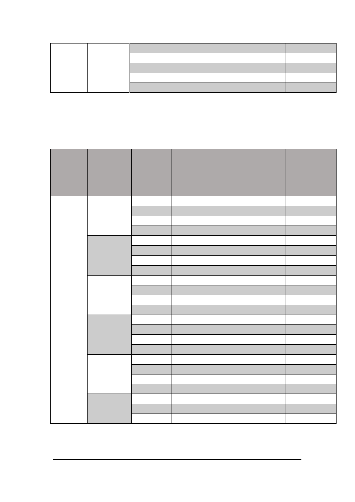
Frequency
Gate Time (Resolution)
1s (0.1 ppm)
0.1 s (1 ppm)
0.01 s (10 ppm)
0.001 s (100 ppm)
[1] Specifications are for 90-minute warm-up, > 3Hz ac filter and sine wave input.
[2] 10% over range on all ranges except ACV 750 V and ACI 10 A ranges.
[3] Relative to calibration standards.
[4] Specifications are for sine wave input >5% of range. For inputs within 1% and 5% of range and <50 kHz, add
0.1% of range additional error. For 50 kHz to 100 kHz, add 0.13% of range additional error.
[5] ACV 750 range limited to 8x10⁷ Volt-Hz. For input over 300 V rms, add 0.7 mV error for each additional volt.
[6] For continuous current > DC 7 A or AC RMS 7 A, 30 seconds ON and 30 seconds OFF.
[7] For frequency beow 100 Hz, the specification of slow filter is only for sine wave input.
[8] Specifications are for sine wave input >5% of range. For inputs within 1% to 5% of range, add 0.1% of range additional
error. Specifications are typical values for 200 uA and 2 mA, 2 A and 10 A ranges when frequency >1 kHz.
Frequency and Period Characteristics
Accuracy ±(% of Reading)
[1] [2]
3 Hz– 5Hz
0
0.12
0.12
0.12
5 Hz– 10 Hz
0
0.17
0.17
0.17
10 Hz–40 Hz
0
0.20
0.20
0.20
40 Hz–100 Hz
0
0.06
0.21
0.21
100 Hz–300 Hz
0
0.03
0.21
0.21
300 Hz–1 kHz
0
0.01
0.07
0.07
>1 kHz
0
0
0.02
0.02
Remarks:
Function
Range
[2]
Test Current
1 Year
TCAL℃±5℃
Temperature
coefficient
0℃ to(TCAL℃ - 5℃)
(TCAL℃ + 5℃)to
50℃
Capacitance
2.0000 nF
10 μA
2 + 2.4
0.05 + 0.06
20.000 nF
10 μA
1 + 0.1
0.05 + 0.01
200.00 nF
100 μA
1 + 0.1
0.01 + 0.01
2.0000 μF
100 μA
1 + 0.1
0.01 + 0.01
20.000 μF
1 mA
1 + 0.1
0.01 + 0.01
200.00 μF
1 mA
1 + 0.1
0.01 + 0.01
2.0000 mF
1 mA
1 + 0.1
0.01 + 0.01
20.000 mF
1 mA
1 + 0.1
0.01 + 0.01
100.00 mF
1 mA
3 + 0.1
0.05 + 0.02
[1] Specifications are for 90 minutes warm-up, using 1 s gate time.
[2] For frequency ≤ 300 kHz, the specification is the 10% to 110% of range of the AC input voltage. For frequency >
300 kHz, the specification is the 20% to 110% of range of the AC input voltage. The maximum input is limited to
750 V rms or 8 ×10
the full range. For 20 mV to 200 mV, multiply % of reading error ×10.
[3] Relative to calibration standards.
7
Volts-Hz (whichever is less). The 200 mV range is full range input or input that is larger than
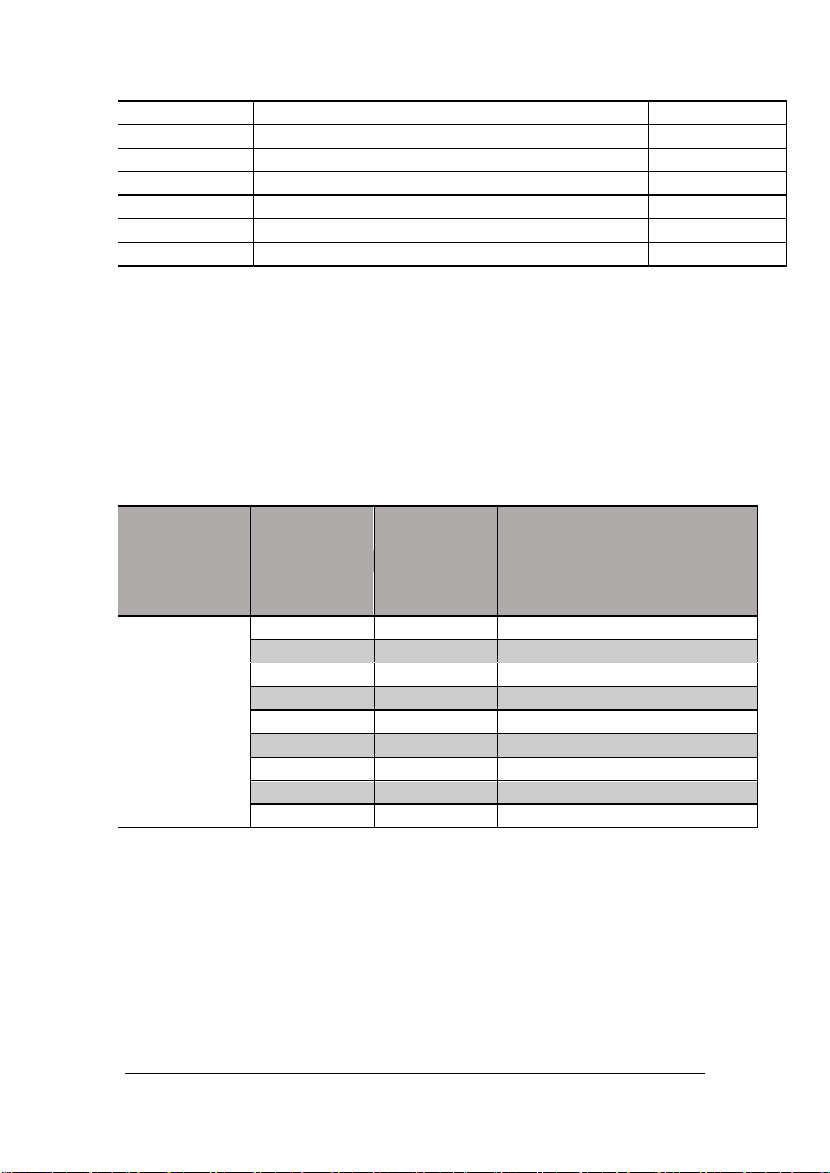
Capacitance Characteristics
Accuracy±(% of Reading + % of Range)
[1]
Remarks:
[1] Specifications are for 90 minutes warm–up and using REL operation. Additional errors may be
caused by
non–film capacitors.
[2] Specifications are the 1% to 110% of range on 2nF range and 10% to 110% of range on all other
ranges
SDM3065X Service Manual 7
 Loading...