

SIGLENT SDL1000X, SDL1020X, SDL1030X User Manual

User Manual
SDL1000X Programmable DC
Electronic Load
UM0801X-C01A
2019 SIGLENT TECHNOLOGIES CO., LTD

SIGLENT
Copyright and Statement
Copyright
SIGLENT TECHNOLOGIES CO., LTD. All rights reserved.
Trademark Information
SIGLENT is registered trademark of SIGLENT TECHNOLOGIES CO., LTD.
Statement
● SIGLENT products are protected by patent laws in and outside of the P.R.
China.
● SIGLENT reserves the right to change the specifications and price.
● Information in this publication replaces all previous corresponding
published material.
● Contents in this manual are not allowed to be copied, extracted or
translated in any form or by any means without SIGLENT’s permission.
SDL1000X User Manual II

SIGLENT
General Safety Summary
Please review the following safety precautions carefully to avoid personal
injury or damage to this product or any product connected to it. To prevent
potential danger, please use the instrument as specified.
Use the proper power cord
Only use the the power cord designed for use with the instrument and
authorized for use with in the local country of interest.
Power supply
AC Input Voltages: 110 V/220 V ± 10%, 50/60Hz.
Use proper fuse
The fuse types: 110 V/220 V: T315 mA/250 V
Make sure to use the correct type of fuse before turning on the instrument.
Do not connect the power cord before replacing the fuse.
Find and fix the root cause of fuse damage before replacing the fuse.
Ground the instrument
The instrument is grounded through the protective terra/Earth conductor of the
power cord. To avoid electric shock, the grounding conductor must be
connected to the earth. Make sure that the instrument is properly grounded
before activating any inputs or outputs.
Observe all terminal ratings
To avoid fire or electric shock, please observe all ratings and symbols on the
instrument. Read this guide carefully to know more details about the ratings
before connection.
Keep proper ventilation
Inadequate ventilation may cause an increase of the internal temperature of
the instrument, which can lead to damage. Please keep proper ventilation and
check the fan and air-vents regularly when using the instrument.
Operating conditions
Location: Indoor, no direct sunlight, minimal interference and pollution
SDL1000X User Manual III

SIGLENT
Relative humidity: < 80%
Altitude: < 2000 m
Temperature: 0℃ to 40℃
Electrostatic Prevention
Operate in an area that minimizes the potential for electrostatic discharge .
Always ground both the internal and external conductors of cables to release
static before connecting.
Do not operate in an explosive atmosphere
To avoid personal injury or damage to instrument, please do not operate in an
explosive atmosphere.
Keep surface of the product clean and dry
Please keep the surface of the product clean and dry.
SDL1000X User Manual IV
SIGLENT
Safety Terms and Symbols
Important terms that may appear on the product and in this manual:
DANGER: Indicates direct injury or hazard that may happen.
WARNING: Indicates potential injury or hazard that may happen.
CAUTION: Indicates potential damage to the instrument or other property that
may happen.
Symbols that may appear on the product:
Hazardous Protective Warning Earth Power
Voltage Earth Terminal Ground Switch
SDL1000X User Manual V
SIGLENT
SDL1000X Brief Introduction
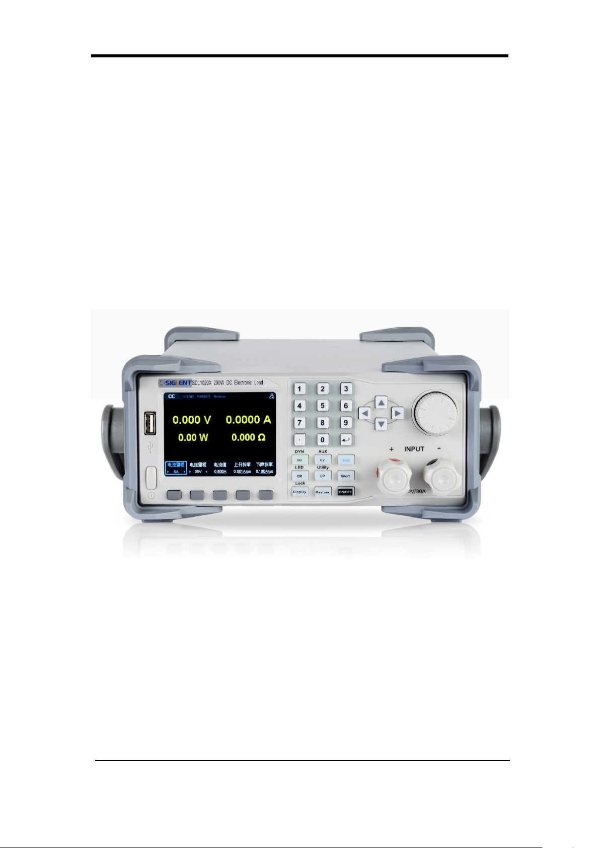
The SDL1000X series Programmable DC Electronic Load has a 3.5 inch
TFT-LCD display , a user-friendly interface and superb performance
specifications. Two versions are available: The SDL1020X features an input
range of 150 V/30 A with a total power of 200 W. The SDL1030X has an input
range of with a total power of 300 W. All models have measurement
resolutions of 0.1 mV/0.1 mA,Adjustable current rise time of 0.001 A/s ~ 2.5
A/s,and built-in RS232/USB/LAN communication interfaces. The SDL1000X
also has a standard SCPI communication protocol that can be used with a
computer to create fully automatic testing platforms. The SDL is ideally
suited for Power, battery, LED, automotive electronics, and aerospace
applications.
Main features of the SDL1000X
SDL1020X (Single channel):DC 150 V/30 A,total power up to 200 W
SDL1030X (Single channel):DC 150 V/30 A,total power up to 300 W
4 static modes / Dynamic mode:CC/CV/CR/CP
CC Dynamic mode:Continuous, pulsed, toggled
CC Dynamic mode: 25 kHz, CP Dynamic mode: 12.5 kHz, CV Dynamic
mode: 0.5 Hz
Adjustable current rising speed: 0.001 A/us ~ 2.5 A/us
SDL1000X User Manual VI

SIGLENT
Min. readback resolution: 0.1 mV, 0.1 mA
Measuring speed of voltage and current: Up to 500 kHz
100 step list function
Over-current protection, over-power protection , battery, short circuit and
CR-LED test functions
4-wire SENSE compensation mode
External voltage and current control function
Voltage and current monitoring via 0-10 V analog output
3.5 inch TFT-LCD display,capable of displaying multiple parameters and
states simultaneously
Built-in RS232/USB/LAN communication interface,USB-GPIB module
(optional)
With memory function in case of power-down
OCP, OVP, OPP, OTP and LRV protections
Wave form graphing
Voltage based rise/fall function
Von and V
function
latch
Smart fan control to minimize noise
Remote control and measurement on PC
SDL1000X User Manual VII

SIGLENT
Content
Copyright and Statement II
General Safety Summary III
Safety Terms and Symbols V
SDL1000X Brief Introduction VI
Chapter 1 Start Guide 1
General Inspection 2
The Front Panel 3
The Rear Panel 6
Connect power 8
User interface 10
Fuse Replacement 13
Chapter 2 Function and Features 14
Local/Remote Operation Mode 15
Local Operation Mode 15
Remote Operation Mode 15
Static Operation Mode 16
Constant Current (CC) Mode 16
Constant Voltage (CV) Mode 18
Constant Resistance (CR) Mode 21
Constant Power (CP) Mode 23
Dynamic test function 25
Continuous mode 26
Pulse mode 29
Toggle mode 32
OCPT Test Function 35
OPPT Test Function 39
Battery Test Function 43
List Test Function 47
Auto Test Function 50
LED Test Function 54
Waveform Display Function 57
Restore 59
Function of Terminals on the Rear Panel 63
Sense mode 63
External trigger function 65
Voltage fault function 66
Current and voltage monitor 66
Short-circuit monitor 66
Protection Functions 66
Overvoltage protection (OVP) 66
SDL1000X User Manual VIII

Overcurrent protection (OCP) 67
Overpower protection (OPP) 67
Over-temperature Protection (OTP) 68
Input Reverse Polarity Protection (RPP) 68
Chapter 3 System Utility Function 69
System 69
1.System info 70
2.Interface 71
2.Sound 75
3.Language 76
4.Factory Setting 76
5.Upgrade 77
6.BoardTest 77
Config 79
Turn ON/OFF the Sense Function 79
Turn ON/OFF SOF Function 79
Break-Over Volatge 79
Turn ON/OFF Von-Latch Function 79
Set Trigger 80
Set Aver 80
Set EXTC(External Interface) 81
SLMT 86
Limit 87
I_Protect 87
P_Protect 88
Troubleshooting 90
Contact SIGLENT 91
SIGLENT
SDL1000X User Manual IX


Chapter 1 Start Guide SIGLENT
Chapter 1 Start Guide
In this chapter, we introduce the front panel and display interface of the
SDL1000X, and also tips for how to check and operate the digital load for the
first time.
The main content of Chapter 1 includes:
General Inspection
The front panel
The rear panel
Connecting power
User interface
Output Inspection
Fuse Replacement

SIGLENT Chapter 1 Start Guide
General Inspection
Please check the instrument according to the following steps.
1. Inspect the shipping container.
Keep the shipping container or cushioning material until the contents of the
shipment have been completely checked and the instrument has passed both
electrical and mechanical tests.
The consigner or carrier will be responsible for damage to the instrument
resulting from shipment. SIGLENT will not provide free maintenance or
replacement.
2. Inspect the instrument.
If there are instrument is found damaged, defective or has failed any electrical
or mechanical tests, please contact SIGLENT.
3. Check the accessories.
Please check the accessories according to the packing list. If the accessories
are incomplete or damaged, please contact SIGLENT.
Chapter 1 Start Guide SIGLENT
1
3
24 6
5
7
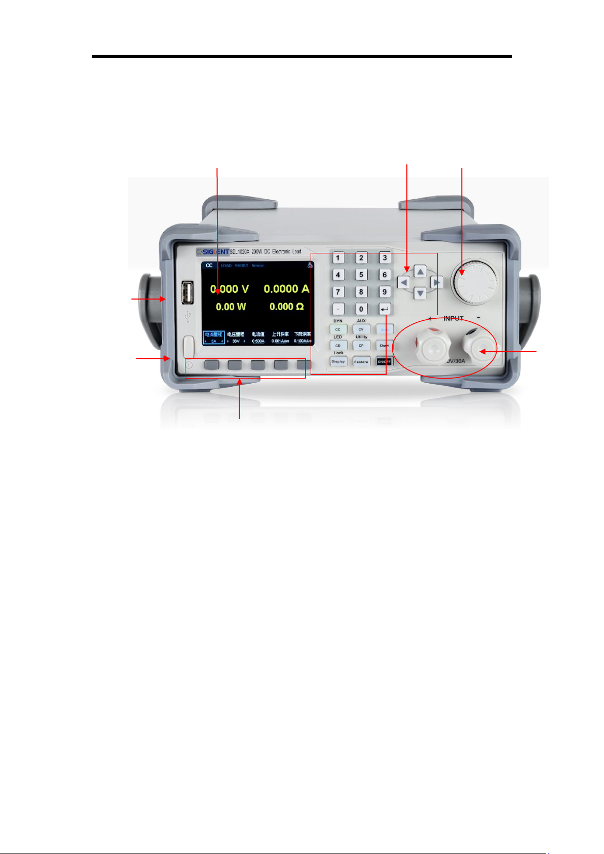
The Front Panel
Figure1: The front panel of the SDL1000X
1. LCD
The load has a 3.5 inch TFT-LCD display which can display system
parameter settings, system output state, wave forms, menu options,
prompt messages, etc.
2. Knob
When setting parameters, rotate the knob to increase or decrease
the value of the digit at the cursor. When browsing setting objects (such
as of the buzzer state, sense, voltage and current protection, store or
read files and switch modes, etc.), rotating the knob can quickly move the
cursor or switch options. Pressing down the knob selects/enters the
parameter.
SIGLENT Chapter 1 Start Guide
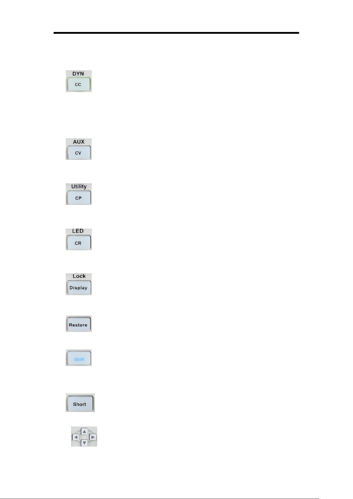
3. Function button and power key
Press down the button to enter the constant current mode.
Enter one of the dynamic modes (DYN mode) by pressing the shift button at
the same time.
Press down the button to enter constant voltage (CV) mode.
Enter auxillary (AUX) mode by pressing the shift button at the same time.
Press down the button to enter the constant power (CP) mode.
Enter Utility mode by pressing the shift button at the same time.
Press down the button to enter the constant resistance (CR)
mode. Enter LED mode by pressing the shift button at the same time
Press down the button to enter the Display mode. Enable the
key lock function by pressing the shift button at the same time.
Press down the button to enter the Restore function
Press down the shift button to access the alternate button
functions like Lock or LED as shown above.
Press down the button to enter the Short function.
The right, left, up, and down arrow buttons move the on-screen

Chapter 1 Start Guide SIGLENT
cursor to select the setting parameter.
0~9 Input the number zero to nine using the keypad.
Dot/Period
Enter
Softkey functions are define by the adjacent on-screen label
4. Input Terminal
Physical input connections to the external circuit and voltage.
5. USB interface
Interface that can be insert USB device and support FAT32 file
system format.
6. Power key
Turn on or off the instrument.
7. Function key
Used to choose different functions.
SIGLENT Chapter 1 Start Guide
1
2
3
4
5
6
10
9
7
8
11
12
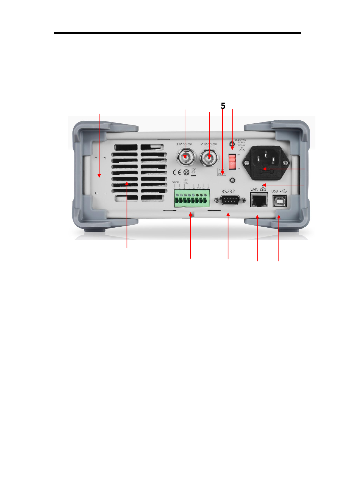
The Rear Panel
Figure 2: The rear panel of the SDL1000X
1. Warning message
Warnings about grounding the instrument and other important
information.
2. AC input voltage description
The frequency and voltage of the AC power supply must match the
specification of the fuse.
3. AC power socket
The power plug socket for AC input power.
4. Fuse

Chapter 1 Start Guide SIGLENT
The specified fuse must be rated for the input voltage (Please refer
to the “ AC input voltage description”)
5. AC line power selection switch
AC Input Voltage: 110/220 V
6. LAN interface
Connect to the local network (LAN) using a standard RJ45 interface.
7. USB device
Connect the instrument (as a controlled device) to an external
computer/controller via USB.
8. GPIB interface
Connect to a controlling computer GPIB card through the IEEE488
bus.
9. Current detection terminal
Observe the current input to the SDL by connecting the current
detection terminal to a measurement instrument (oscilloscope, DMM) to
analyze the change of input current with respect to time.
10. Voltage detection terminal
Observe the voltage input to the SDL by connecting the voltage
detection terminal to a measurement instrument (oscilloscope, DMM) to
analyze the change of input voltage with respect to time.
11. Sense terminal, External control terminal, PWM output terminal
Select different ports to realize its function
12. FAN
SIGLENT Chapter 1 Start Guide
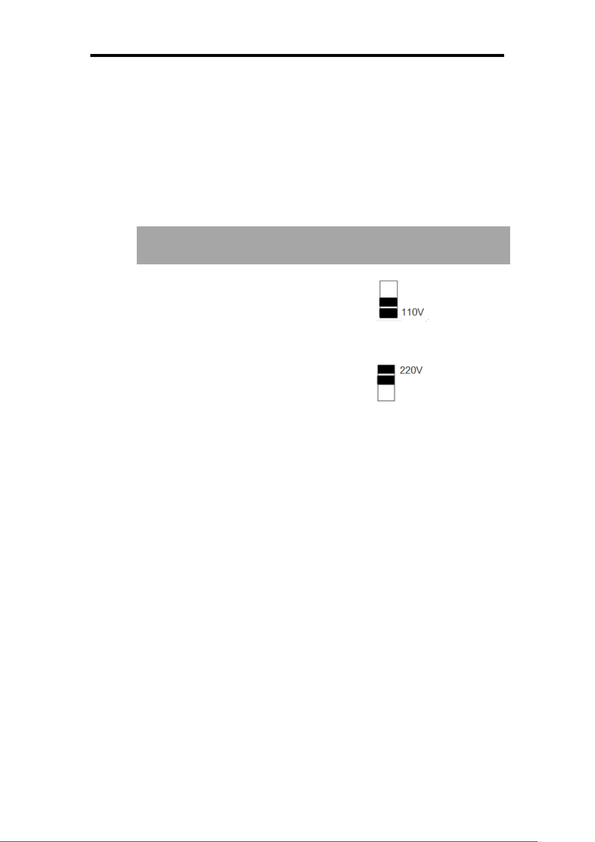
AC power input
Voltage selector
configure
110 VAC ± 10%, 50 ~ 60 Hz
220 VAC ± 10%, 50 ~ 60 Hz
Connect power
The SDL1000X supports a variety of AC line power input values. For
each line voltage, the rear panel voltage selector settings are different, as
shown in table 1 below.
Table 1: AC input line power specifications
Please connect the power carefully follow the steps below:
1. Check the input power
Make sure that the AC line power to be connected to the instrument
and meets the requirements in Table 1.
2. Check the voltage selector at the rear panel
Make sure that the voltage selector setting at the rear panel of the
instrument matches the actual input voltage.
3. Check the fuse
The specified fuse is installed when the instrument leaves factory.
Please check whether the fuse matches the actual input voltage
according to the "Input Power Requirements" at the rear panel of the
instrument.
Chapter 1 Start Guide SIGLENT
WARNING
To avoid electric shock, make sure that the instrument is correctly
grounded.
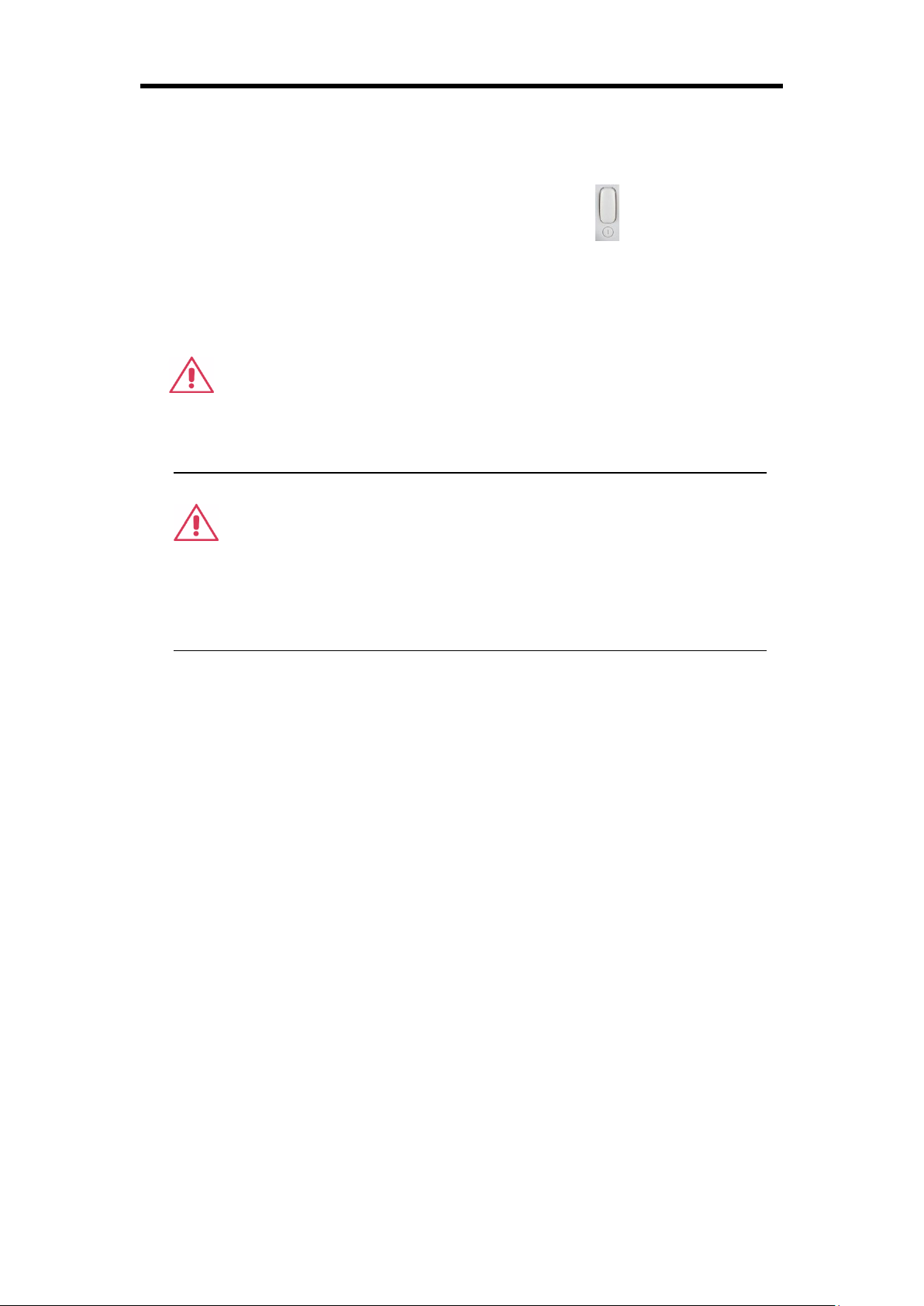
4. Connect the power
Connect the instrument to AC power supply using the power cord
provided in the accessories. Then press the button to turn on the
electronic load.
WARNING
Before turning the instrument on, please disconnect the power supply
and set the voltage selector to the appropriate value.
SIGLENT Chapter 1 Start Guide
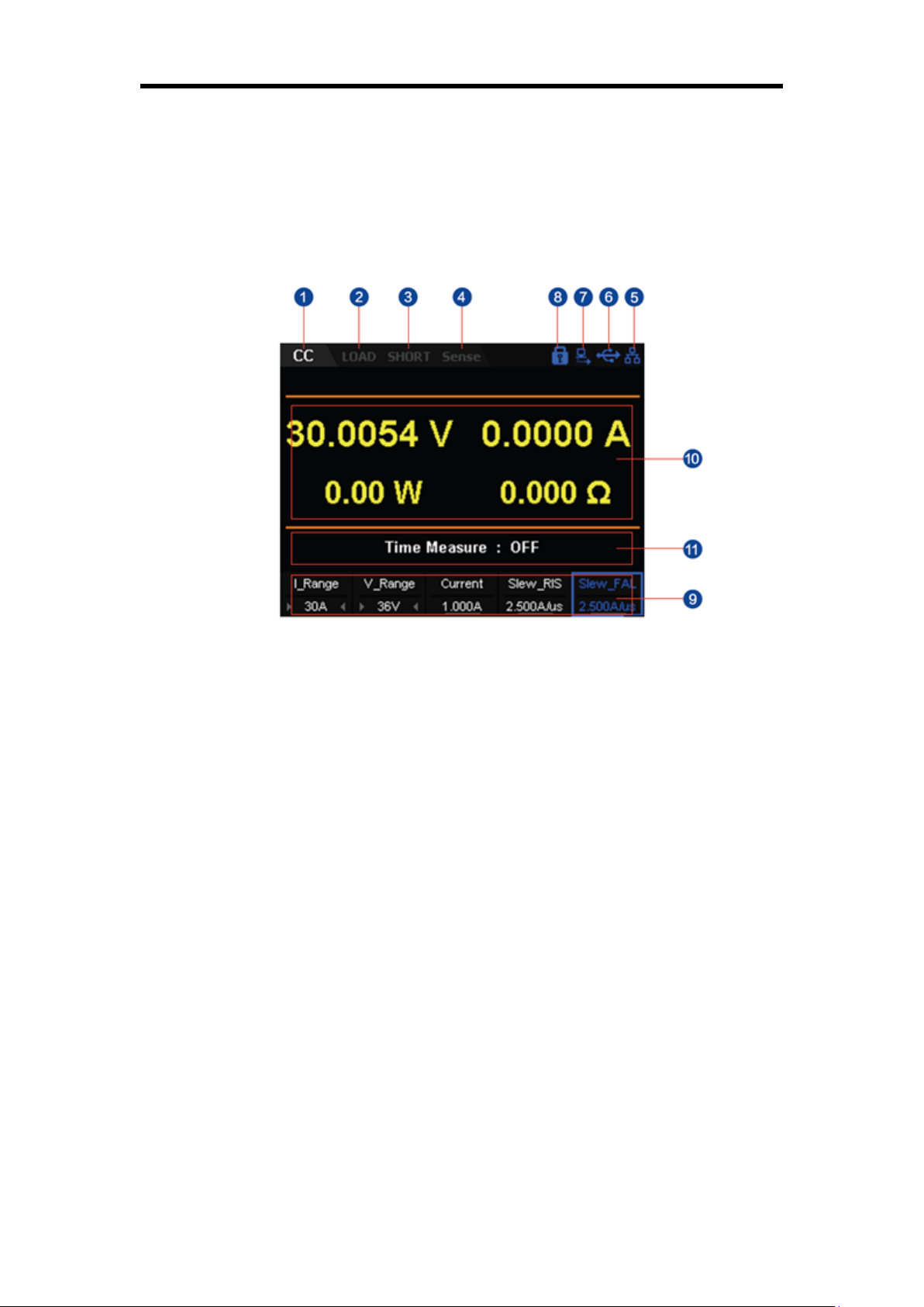
User interface
Figure 3: The user interface of the SDL1000X
1. Channel output mode
2. Channel output state
3. Short state
4. Remote sense mode
5. LAN connection icon
6. USB connection icon
7. Remote mode
8. Keyboard lock

Chapter 1 Start Guide SIGLENT
9. Setting value
10. Measured output values
11. Voltage rise and fall time
SIGLENT Chapter 1 Start Guide
To Power on the instrument
After the instrument is connected to the power source, press the Power key
at the left bottom of the front panel to power on the instrument. When the
instrument is turned on, it will undergo a self-test. If the instrument passes the
self-test, the welcome interface is displayed. If the instrument fails, the
self-test failure information will be displayed. If you encounter any problems
or failures, please contact your nearst SIGLENT support office.
CAUTION
Ensure that the AC selector setting on the rear panel of the
instrument matches the actual AC input voltage, otherwise, the
electronic load could be damaged.
CAUTION
Please pay attention to the positive and negative polarities of the
electronic load to avoid incorrect connections. Otherwise, the load
can be damaged.

Chapter 1 Start Guide SIGLENT
To avoid personal injuries, unplug the power supply before replacing
the fuse. To avoid electric shock or fire, select the proper power supply
specification and replace only with the proper fuse.
Input voltage
Fuse specification
110 VAC
T315mA
220 VAC
T315mA
Fuse Replacement
The specifications of the fuse are relative to the actual input line voltage
shown in the table below. You also can refer to the rear panel “input power
requirement”.
To replace the fuse, please follow the steps below:
1. Turn off the instrument and remove the power cord.
2. Insert a small straight screwdriver into the slot at the power socket
and gently pry out the fuse seat.
3. Adjust the power voltage selector manually to select the correct
voltage scale.
4. Take out the fuse and replace it with the specified fuse (for the
corresponding relations between the input voltage and fuse
specification, refer to the “input power requirement” at the rear
panel).
5. Re-insert the fuse holder into the power socket (please pay attention
to the direction).
WARNING

SIGLENT Chapter 2 Function and Features
Chapter 2 Function and Features
Contents in this chapter:
Local/Remote Operation Mode
Static Operation Mode
Transient Test Function
OCPT Test Function
OPPT Test Function
Auto Test Function
LED Test Function
Waveform Display Function
Store and Recall
Rear Panel Terminal functions
Short monitor function
Protective function
SDL1000X User Manual 14

Chapter 2 Function and Features SIGLENT
Local/Remote Operation Mode
The load provides two operation modes: Local and remote.
Local Operation Mode
After you power on the instrument, it enters the local operation mode by default.
In the local operation mode, all the keys on the front panel are available for you
to use.
Remote Operation Mode
In the remote operation mode, you can send programming commands from a
controller (computer) via any one of the interfaces (GPIB, USB, RS232, or
LAN). In remote operation mode, all the keys (except the Shift key plus the
Display key) will be disabled. This is known as “local lock out”. When locked,
the instrument front panel is disabled and the load can only be controlled via
programming commands. To return to the local operation mode, press the
Shift key plus the Display key on the front panel.
SDL1000X User Manual 15
SIGLENT Chapter 2 Function and Features
Static Operation Mode
The static operation modes include the following 4 modes:
Constant Current (CC) Mode
Constant Voltage (CV) Mode
Constant Resistance (CR) Mode
Constant Power (CP) Mode
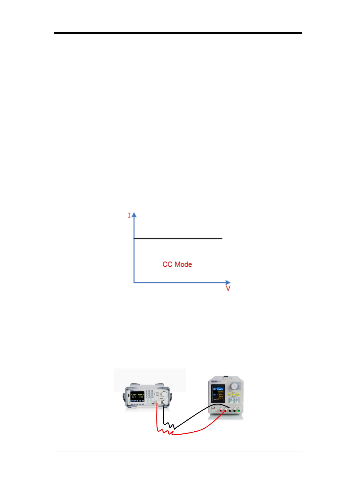
Constant Current (CC) Mode
In CC mode, the electronic load will sink a current in accordance with the
programmed value regardless of the input voltage, as shown in Figure 2-1.
Figure 2-1 Voltage-Current Relationship Schema under CC Mode
Operating Steps
1. Turn off the instrument, as shown in Figure 2-2, connect the DUT
and the channel input terminals on the front panel of the load.
SDL1000X User Manual 16
Constant Current Mode
Chapter 2 Function and Features SIGLENT
Figure 2-2
CAUTION
While making a connection, the positive polarity of the load should
be connected to the (+) terminal of the channel output, and the
negative polarity of the load to the (-) terminal of the channel
output. Incorrect polarity may cause damage to the instrument or
the DUT.
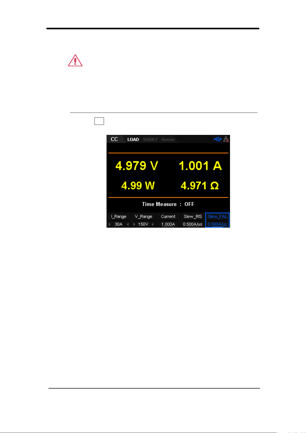
2. Press CC to enter the main interface of CC mode, as shown in
Figure 2-3.
3.
Figure 2-3 CC Mode Main Interface
4. Set CC mode current range (5 A or 30 A) and voltage mode (36 V
or 150 V)
Note: The lower ranges provide better resolution and accuracy at
low current settings.
5. Set the current input value. This is the amount of current that the
load will attempt to draw when the output is enabled.
6. Set the rising slew rate and the falling slew rate in CC mode. The
default unit for the slew rate is A/us.
7. Press On/Off to turn on the channel input. At this time, the actual
input voltage, current, resistance and power will be displayed on
the main interface.
Note: The load will begin to sink current only if the input voltage is
greater than the conduction voltage of the system (default
value is 0 V).
SDL1000X User Manual 17
SIGLENT Chapter 2 Function and Features
Warning
To avoid electric shock, ensure that the DUT is connected to the
input terminals of the load properly before you turn on the channel
input.
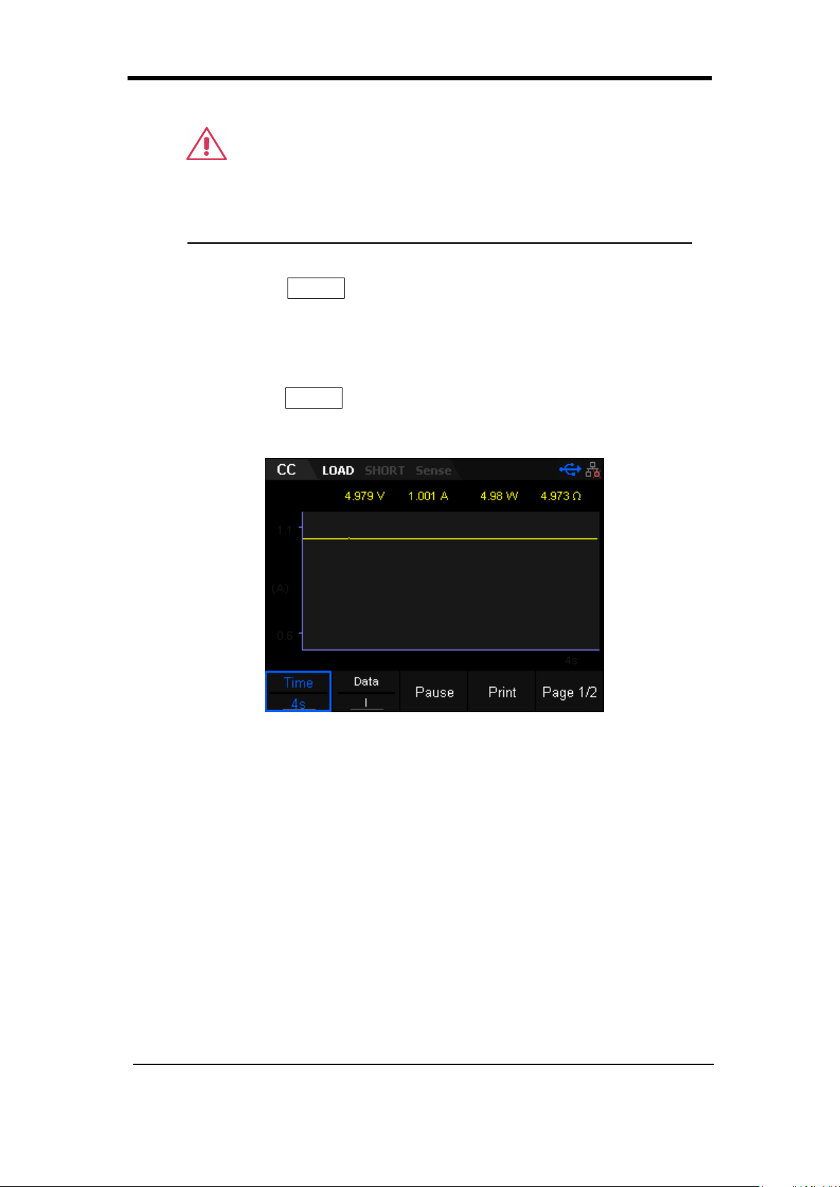
8. Press the Display key to enter the waveform display interface, as
shown in Figure 2-4. By default, the current waveform is displayed.
When the input voltage changes, the load will sink a constant
current.
Press the Display key again to exit the waveform display interface
and return to the main interface of CC mode.
Figure 2-4 Waveform display interface of CC Mode
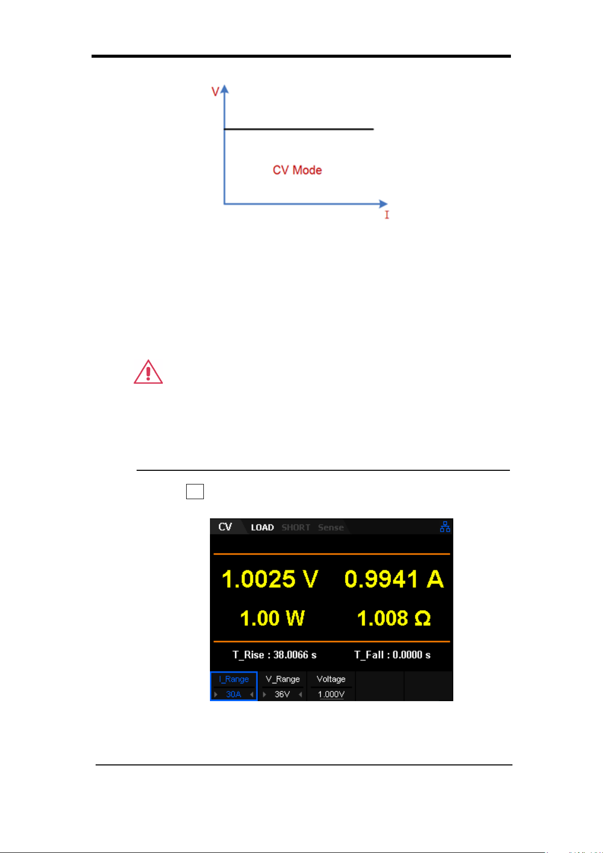
Constant Voltage (CV) Mode
In CV mode, the electronic load will sink enough current to maintain the input
voltage at the setpoint, as shown in Figure 2-5.
SDL1000X User Manual 18
Chapter 2 Function and Features SIGLENT
Constant voltage mode
Figure 2-5 Voltage-Current Relationship Schema under CV Mode
Operating Steps
1. Turn off the instrument, as shown in Figure 2-2, connect the DUT
and the channel input terminals on the front panel of the load.
CAUTION
While making a connection, the positive polarity of the load should
be connected to the (+) terminal of the channel output, and the
negative polarity of the load to the (-) terminal of the channel
output. Incorrect polarity may cause damage to the instrument or
the DUT.
2. Press CV to enter the main interface of CV mode, as shown in
Figure 2-6.
Figure 2-6 CV Mode Main Interface
3. Set CV mode current range (5 A or 30 A) and voltage range (36 V
SDL1000X User Manual 19
SIGLENT Chapter 2 Function and Features
or 150 V)
Note: The low range provides better resolution and accuracy at
low voltage settings.
4. Set voltage
5. Press On/Off to turn on the channel input. At this time, the actual
input voltage, current, resistance and power will be displayed on
the main interface.
Note: The load will sink current only if the input voltage is larger than
the conduction voltage of the system (default value is 0 V).
Warning
To avoid electric shock, ensure that the DUT is connected to the
input terminals of the load properly before you turn on the channel
input.
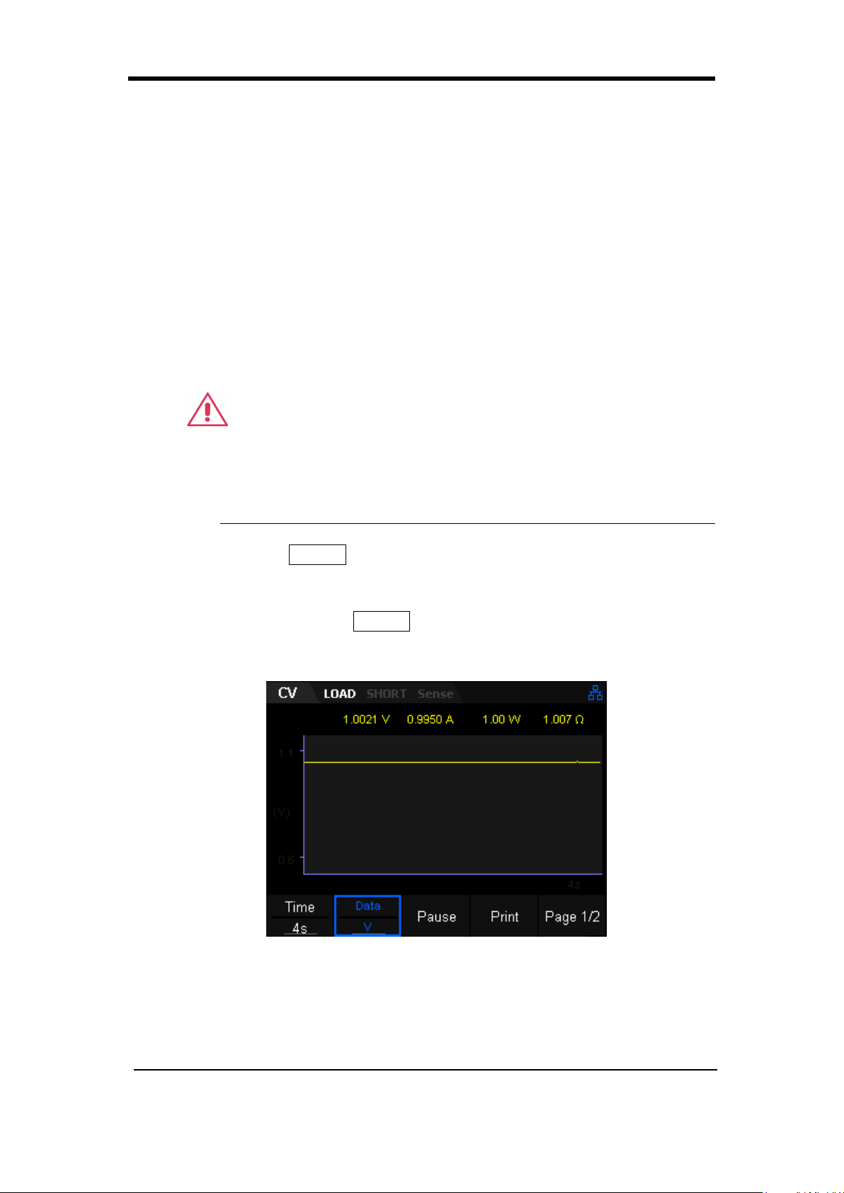
6. Press the Display key to enter the waveform display interface, as
shown in Figure 2-7. By default, the voltage waveform is displayed.
When the input current changes, the load will apply a constant
voltage. Press the Display key again to exit the waveform display
interface and return to the main interface of CV mode.
Figure 2-7 Waveform display interface of CV Mode
SDL1000X User Manual 20
 Loading...