

SIGLENT SDG800 Series, SDG1000 Series User Manual

User Manual
SDG800 Series Function/Arbitrary Waveform Generator
UM02008-E02B
2014 SIGLENT TECHNOLOGIES CO., LTD

SDG800 User Manual I
Declaration
Copyright © SIGLENT TECHNOLOGIES CO., LTD. All rights reserved.
Contents in this Manual are not allowed to be copied, extracted and
translated before being allowed by SIGLENT Company

SDG800 User Manual II
General Safety Summary
Review the following safety precautions to avoid injury and prevent damage
to this product or any products connected to it. To avoid potential hazards,
use this product only as specified.
Only qualified personnel should perform service procedures.
To Avoid Fire or Personal Injury
Use proper power line. Only the special power line of the products
approved by the state should be used.
Ground the instrument. This generator is grounded through the
protective terra conductor of the power cord. To avoid electric
shock, the grounding conductor must be connected to the earth
ground. Make sure that the instrument is properly grounded before
connecting the input or output terminals.
Observe all the ratings of the terminal. To avoid fire or shock,
observe all the ratings and symbols that marked on the instrument.
Read the user guide carefully before making connections to the
instrument.
Do not operate without Covers. Do not operate the product with
covers or panels removed.
Avoid circuit or wire exposed. Do not touch the exposed
connections or components when the power is on.
Do not operate with suspected failures. If you suspect there is
damage with this product, you should have it inspected by
qualified service personnel authorized by SIGLENT before further
operations.

SDG800 User Manual III
Provide proper ventilation.
Do not operate in wet/damp conditions.
Do not operate in an explosive atmosphere.
Keep the product’s surfaces clean and dry.
Not position the equipment so that it is difficult to operate the
disconnecting device (detachable plug)

SDG800 User Manual IV
If the equipment is used in a manner not specified by the manufacturer, the
protection provided by the equipment may be impaired.
This product has been tested to the requirements of
CAN/CSA-C22.2 No. 61010-1, second edition, including Amendment 1,
or a later version of the same standard incorporating the same level of
testing requirements.
Not to use the product for measurements within other measurement
categories, such as CAT II, CAT III, CAT IV.
Not to use the equipment for measurements on mains circuits, not to
use the equipment for measurements on voltage exceed the voltage
range describe in the manual.
Only probe assemblies which meet the manufacturer’s specifications
shall be used.
The Responsible body or operator should refer to the instruction
manual to preserve the protection afford by the equipment. If the
equipment is used in a manner not specified by the manufacturer, the
protection provided by the equipment may be impaired.
Any parts of the device and its accessories are not allowed to be
changed or replaced, other than authorized by the manufacturer of his
agent.
SDG800 User Manual V
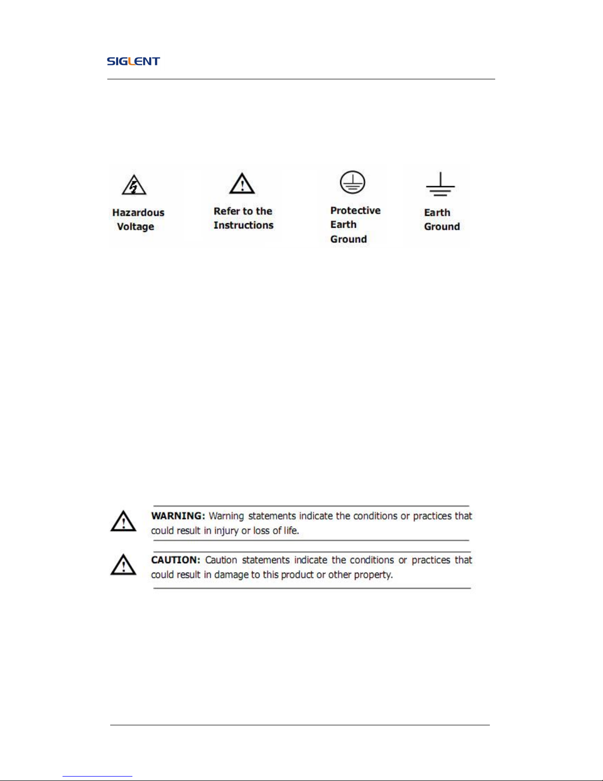
Safety Terms and Symbols
Terms in this guide, these terms may appear in this manual:
Terms on the product, terms below may appear on the product:
DANGER: Indicates an injury or hazard that may immediately happen.
WARNING: Indicates an injury or hazard that may not immediately happen.
CAUTION: Indicates that a potential damage to the instrument or other
property might occur.
Symbols on the product: Symbols as followed may appear on the product:

SDG800 User Manual VI
Introduction of SDG800 Series
The manual covers the following three types of SDG800 Series
Function/Arbitrary Waveform Generators: SDG830,SDG810, SDG805.
SDG800 Series Function/Arbitrary Waveform Generators adopt the direct
digital synthesis (DDS) technology, which can provide stable, high-precision,
pure and low distortion signals. Its combination of excellent system features,
easiness in usage and versatile functions makes this generator a perfect
solution for your job now and in the future.
SDG800 Series Function/Arbitrary Waveform Generator has a clear and
simple front-panel. The user-friendly panel layout and instructions, versatile
terminals, direct graph interface, built-in instructions and help system have
greatly simplified the operation process, with the help of which, users do not
have to spend a great deal of time learning and familiarizing the operation of
the generator before they can use it proficiently. The built-in AM, DSB-AM,FM,
PM, ASK, FSK and PWM modulation functions generate modulated
waveforms at ease, without the help of a separate modulating source. USB
I/O is a standard accessory, while GPIB is optional. Remote instructions meet
the SCPI specification requirements.
From the characteristics and specifications given below, you will understand
how SDG800 can satisfy your requirements.

SDG800 User Manual VII
DDS technology provides precise, stable and low distortional
output signal.
3.5’TFT color LCD display.
125MSa/s sampling rate, 14-bit resolution.
Frequency characteristics:
Sine: 1μHz to 30MHz
Square: 1μHz to 10 MHz
Ramp: 1μHz to 300kHz
Pulse: 500μHz to 5MHz
White Noise: 10MHz bandwidth (-3dB)
Arbitrary: 1μHz to 5MHz
5 standard waveforms: Sine, Square, Ramp, Pulse, Noise
Self-defined arbitrary waveform
Multiple modulation function: AM, FM, PM, ASK, FSK, PWM,
DSB-AM, Sweep and Burst.
Multiple interfaces: USB host & USB device(USBTMC)
Support USB storage device. Software updating could also be
performed using USB devices.
Up to 16k sample points of internal waveform depth, which can
rebuild or simulate any complex waveform.
2 languages (English and Chinese) user interface and built-in help
system.
Note:
All the specifications described in this guide are according to SDG830. If you
need to know the particular specifications about the other types, please see
datasheet..

SDG800 User Manual VIII
Catalogue
General Safety Summary ................................................................................. II
Introduction of SDG800 Series ...................................................................... VI
1. Getting Started ........................................................................................... 1
1.1. General Inspection ........................................................................... 2
1.2. Handle Adjustment ........................................................................... 3
1.3. The Front/Rear Panel ....................................................................... 4
1.4. To Set a Waveform ........................................................................... 7
1.5. To Set Modulate/Sweep/Burst ........................................................ 12
1.6. To Set Output ................................................................................. 14
1.7. To Use Digital Input ........................................................................ 15
1.8. To Use Store/Utility/Help Function .................................................. 16
2. Operating Your Generator ........................................................................ 17
2.1. To Set Sine Signals ........................................................................ 18
2.2. To Set Square Signals .................................................................... 23
2.3. To Set Ramp Signals ...................................................................... 26
2.4. To Set Pulse Signals ...................................................................... 29
2.5. To Set Noise Signals ...................................................................... 33
2.6. To Set Arbitrary Signals .................................................................. 35
2.7. To Generate the Modulated Waveform ........................................... 42
2.8. To Generate Sweep ........................................................................ 51
2.9. To Generate Burst .......................................................................... 53
2.10. To Store and Recall ..................................................................... 57
2.11. To Set the Utility Function............................................................ 63
2.12. Test/Cal ....................................................................................... 74
2.13. Edition Information ...................................................................... 79
2.14. Updating Firmware ...................................................................... 81

SDG800 User Manual IX
2.15. How to Use the Built-in Help System .......................................... 82
3. Application and Examples ....................................................................... 83
3.1. Example 1:Generate a Sine Wave ................................................. 84
3.2. Example 2:Generate a Square Wave ............................................. 86
3.3. Example 3:Generate a Ramp Wave ............................................... 88
3.4. Example 4:Generate a Pulse Wave................................................ 90
3.5. Example 5:Generate a Noise Wave ............................................... 92
3.6. Example 6:Generate an Arbitrary Wave ......................................... 93
3.7. Example 7:Generate a Sweep Linear Wave ................................... 95
3.8. Example 8:Generate a Burst Wave ................................................ 97
3.9. Example 9:Generate an AM Wave ................................................. 99
3.10. Example 10:Generate a FM Wave ............................................ 101
3.11. Example 11:Generate a PM Wave ............................................ 103
3.12. Example 12:Generate a FSK Wave .......................................... 105
3.13. Example 13:Generate an ASK Wave ........................................ 107
3.14. Example 14: Generate a PWM Wave ........................................ 109
3.15. Example 15: Generate a DSB-AM Wave .................................. 111
4. Troubleshooting ..................................................................................... 113
General Inspecting ................................................................................ 113
Troubleshooting .................................................................................... 114
5. Service and Support .............................................................................. 115
Maintain summary................................................................................. 115
Contact SIGLENT ................................................................................. 116
6. Appendix ................................................................................................ 117
Appendix A: Accessories ....................................................................... 117
Appendix B: Daily Maintain and Cleaning ............................................. 118

SDG800 User Manual 1
1. Getting Started
This chapter covers the following topics:
General Inspection
Handle Adjustment
The Front/Rear Panel
To Set a Waveform
To Set Modulate/Sweep/Burst
To Set Output
To Use Digital Input
To Use Store/Utility/Help Function

SDG800 User Manual 2
1.1. General Inspection
When you get a new SDG800 Series Function/Arbitrary Waveform Generator,
you are suggested to take the following steps to inspect the instrument.
1. Inspect the shipping container for damage.
If there are damages in the packing or foam, keep them until the whole
machine and the accessories pass the electric and mechanical testing.
2. Check the accessories.
Accessories supplied with the instrument are listed in chapter 6
‘Appendix A: Accessories’.
If the contents are incomplete or damaged, please notify your sales
representative.
3. Inspect the instrument.
In case any mechanical damage or defect, or if the instrument does not
operate properly or pass performance tests, notify your sales
representative. If the shipping container is damaged, or the cushioning
materials show signs of stress, notify the carrier as well as your sales
office. Keep the shipping materials for the carrier’s inspection. Offices
will arrange for repair or replacement at their option without waiting for
claim settlement.
SDG800 User Manual 3
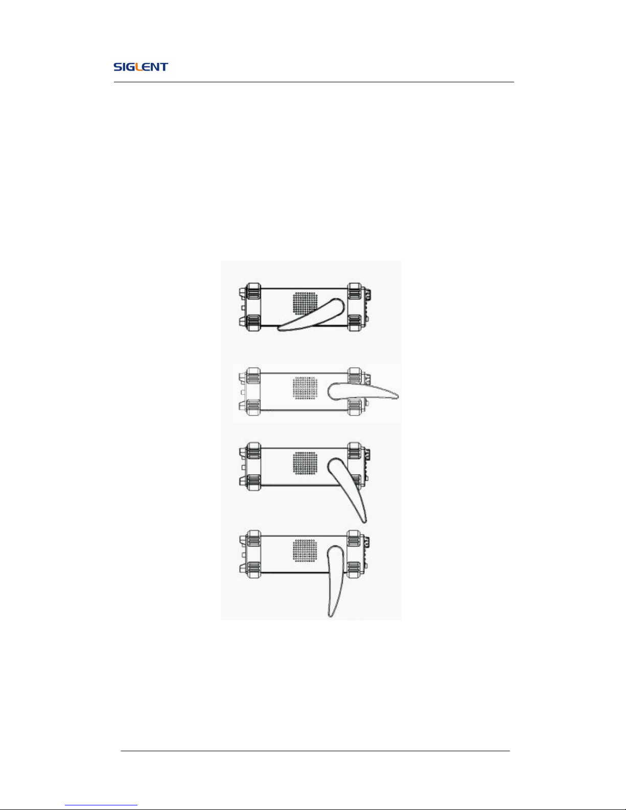
1.2. Handle Adjustment
To adjust the handle position of SDG800 Function/Arbitrary Waveform
Generator, please grip the handle by the sides and pull it outward. Then,
make the handle rotate to the desired position.
Figure 1- 1 Viewing Position and Carrying Position
SDG800 User Manual 4
1.3. The Front/Rear Panel
When you get a new SDG800 Series Function/Arbitrary Waveform Generator,
first you need to understand how to operate the front/rear panel correctly.
This chapter will make a brief introduction and description for the operation
and functions of the front/rear panel.
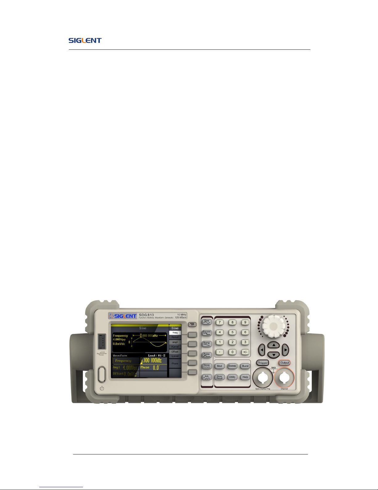
The SDG800 Series Function/Arbitrary Waveform Generator has a clear and
simple front panel. See Figure 1- 2 and Figure 1- 3. The front panel has a
knob and functional keys. The 5 blue grey buttons on the right side of the
screen are menu buttons (named F1 to F5 from up to down) with the help of
which, you can enter different functions menu or have direct specific
applications. The signal input and output interfaces are set at the front and
rear panels which can help generating multiple arbitrary waveforms. The
various interfaces can meet the need of the multiple interface
communications.
Figure 1- 2 SDG800 Series
SDG800 User Manual 5
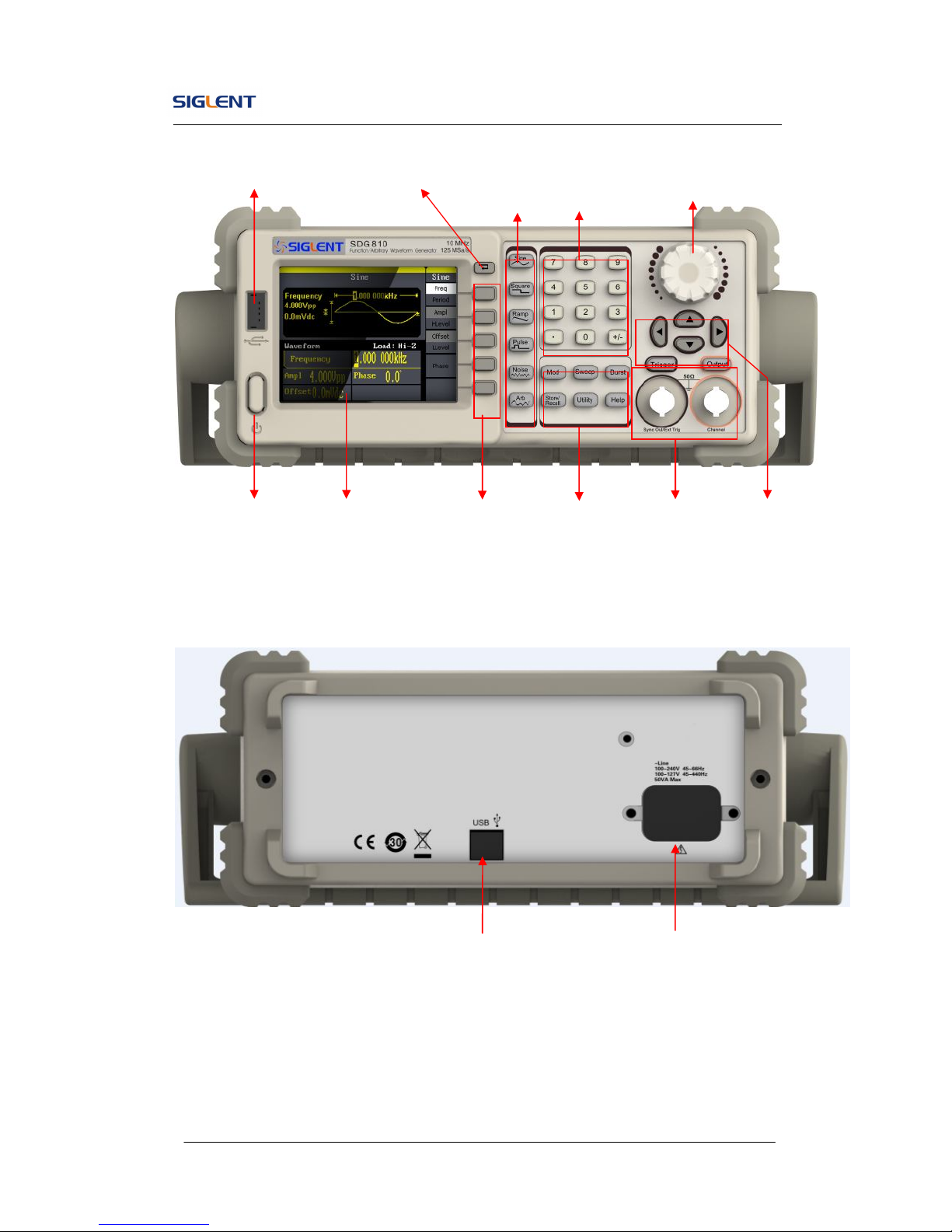
Figure 1- 3 Front Panel of SDG800 Series
Figure 1- 4 Rear Panel of SDG800 Series
Power Socket
Waveform
keys
Number
keys
Power
LCD
Display
Menu
Operation Function
keys
Output
Control
Direction
keys
Back
SDG800 User Manual 6
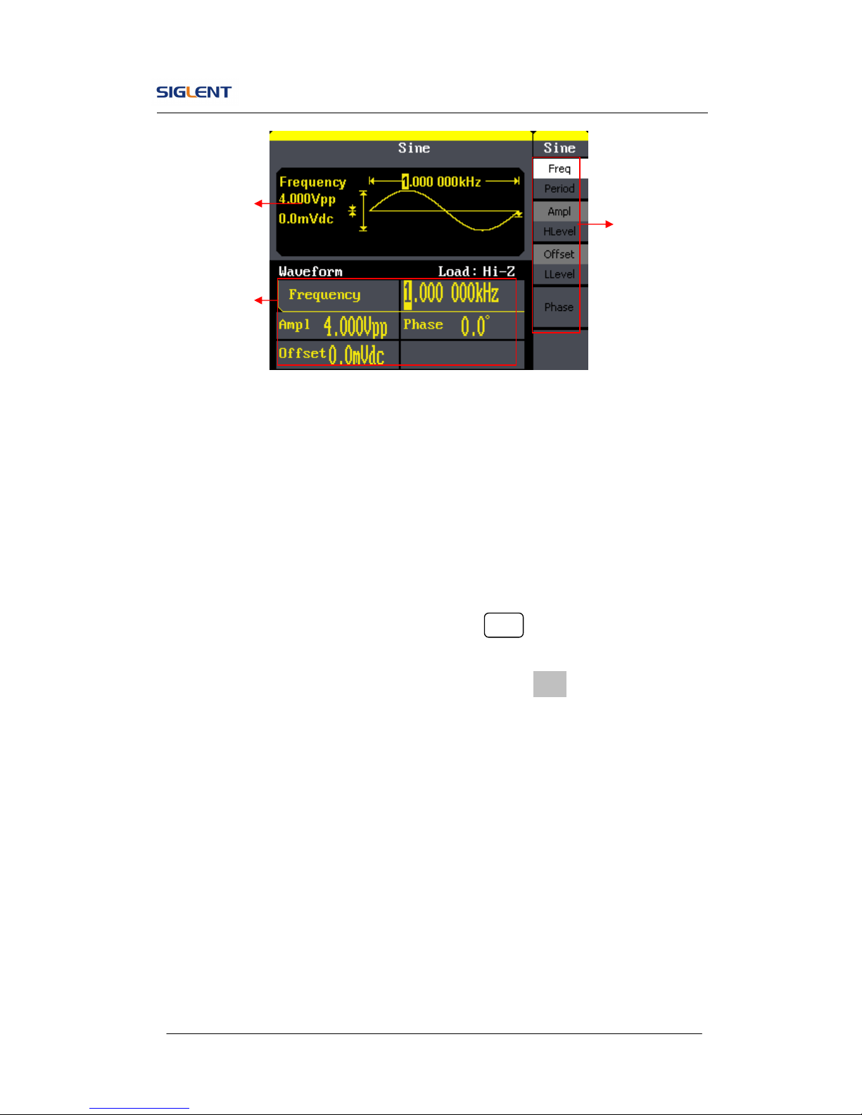
Figure 1- 5 Display Interface (Sine Wave is the default display signal)
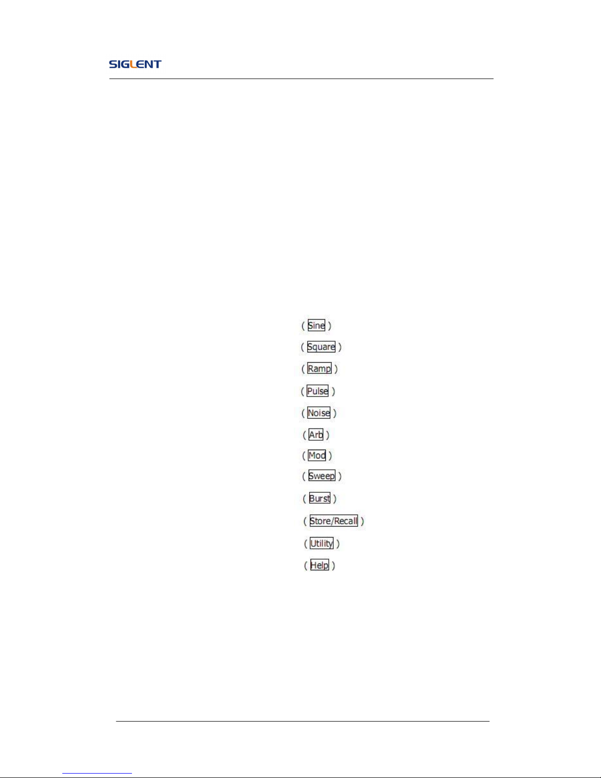
Character definitions in this User Manual:
The signs for buttons in this manual are the same as the panel buttons.
Please note that, the signs for the functional buttons on the operation panel
are represented by squared words, such as Sine , which represents the
transparent functional key with Sine on it on the front panel, while the menu
buttons are represented by brighten words such as Freq, which means the
frequency option in the Sine menu.
Waveform
Display area
Parameter area
Operation
Menu:
SDG800 User Manual 7
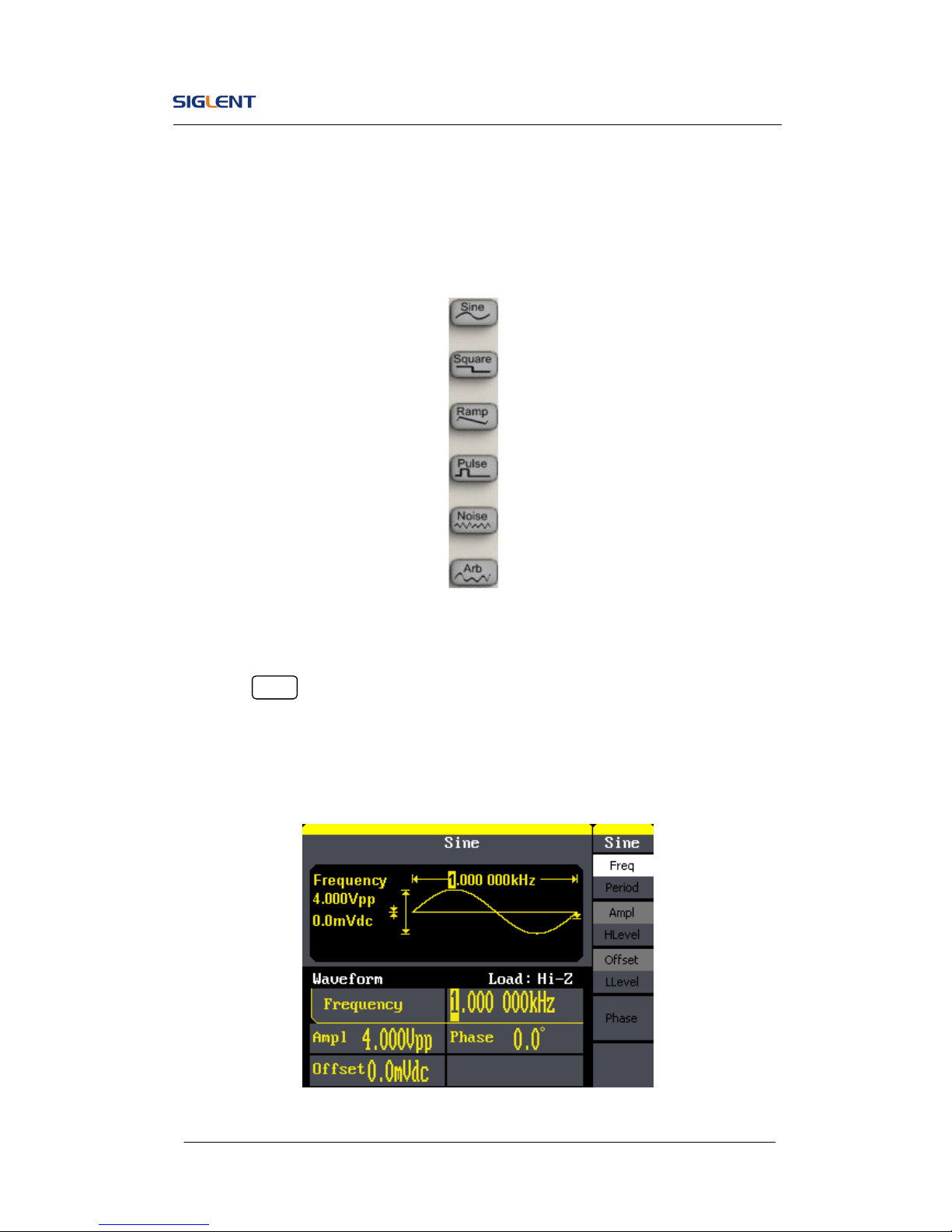
1.4. To Set a Waveform
On the operation panel, there is a set of buttons with waveform icon. See
Figure 1- 6. The exercise below will help you familiarize with the waveform
selection settings.
Figure 1- 6 Waveform Selection Buttons
1. Press Sine button and the waveform window will display sine waveform.
SDG800 Series Generator can generate sine signal with a frequency
from 1μHz to 30MHz. By setting frequency/period, amplitude/high level,
offset/low level, sine signal with different parameters can be generated.
Figure 1- 7 Sine Signal Display Interface
SDG800 User Manual 8
As is shown in Figure 1- 7, the default signal parameters are: 1kHz frequency,
4.0Vpp amplitude and 0Vdc offset.
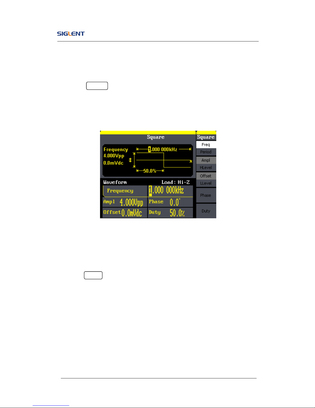
2. Press Square button, and the waveform window displays square
waveform. SDG800 Series Generator can generate square signal with a
frequency from 1μHz to 10MHz and variable duty cycle.
Figure 1- 8 Square Signal Display Interface
As is shown in Figure 1- 8, the default signal parameters are: 1kHz frequency,
4.0Vpp amplitude, 0Vdc offset and 50% duty cycle.
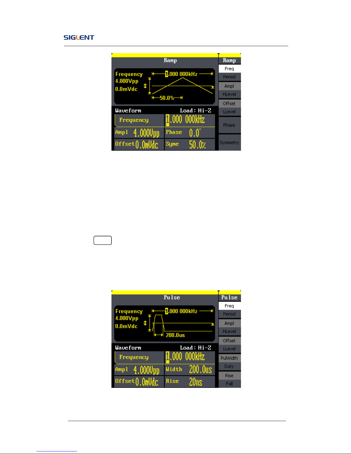
3. Press Ramp button, and the waveform window displays ramp waveform.
SDG800 Series Generator can generate ramp signal with a frequency of
from 1μHz to 300kHz and variable symmetry.
SDG800 User Manual 9
Figure 1- 9 Ramp Signal Display Interface
As is shown in Figure 1- 9, the default signal parameters are: 1kHz frequency,
4.0Vpp amplitude, 0Vdc offset and 50% symmetry.
4. Press Pulse button, and the waveform window displays pulse waveform.
SDG800 Series Generator can generate pulse signal with a frequency
from 500μHz to 5 MHz and variable pulse width and delay.
Figure 1- 10 Pulse Signal Display Interface
SDG800 User Manual 10
As is shown in Figure 1- 10, the default signal parameters are: 1kHz
frequency, 4.0Vpp amplitude, 0Vdc offset, 200μs pulse width.
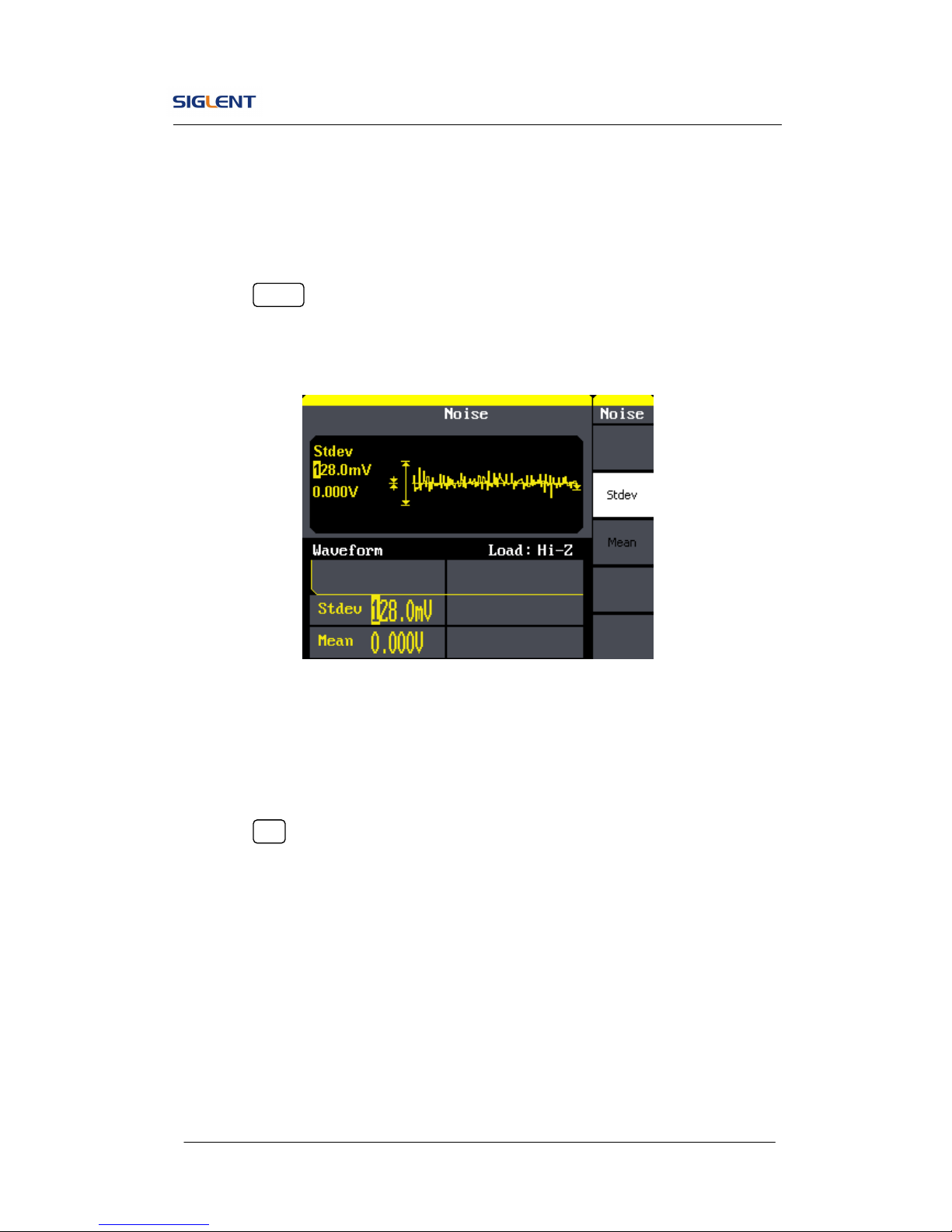
5. Press Noise button, and the waveform window displays noise waveform.
SDG800 Series Generator can generate noise signal with a band width
up to 10MHz.
Figure 1- 11 Noise Signal Display Interface
As is shown in Figure 1- 11, the default signal parameters are: 128mV stdev
and 0mV Mean.
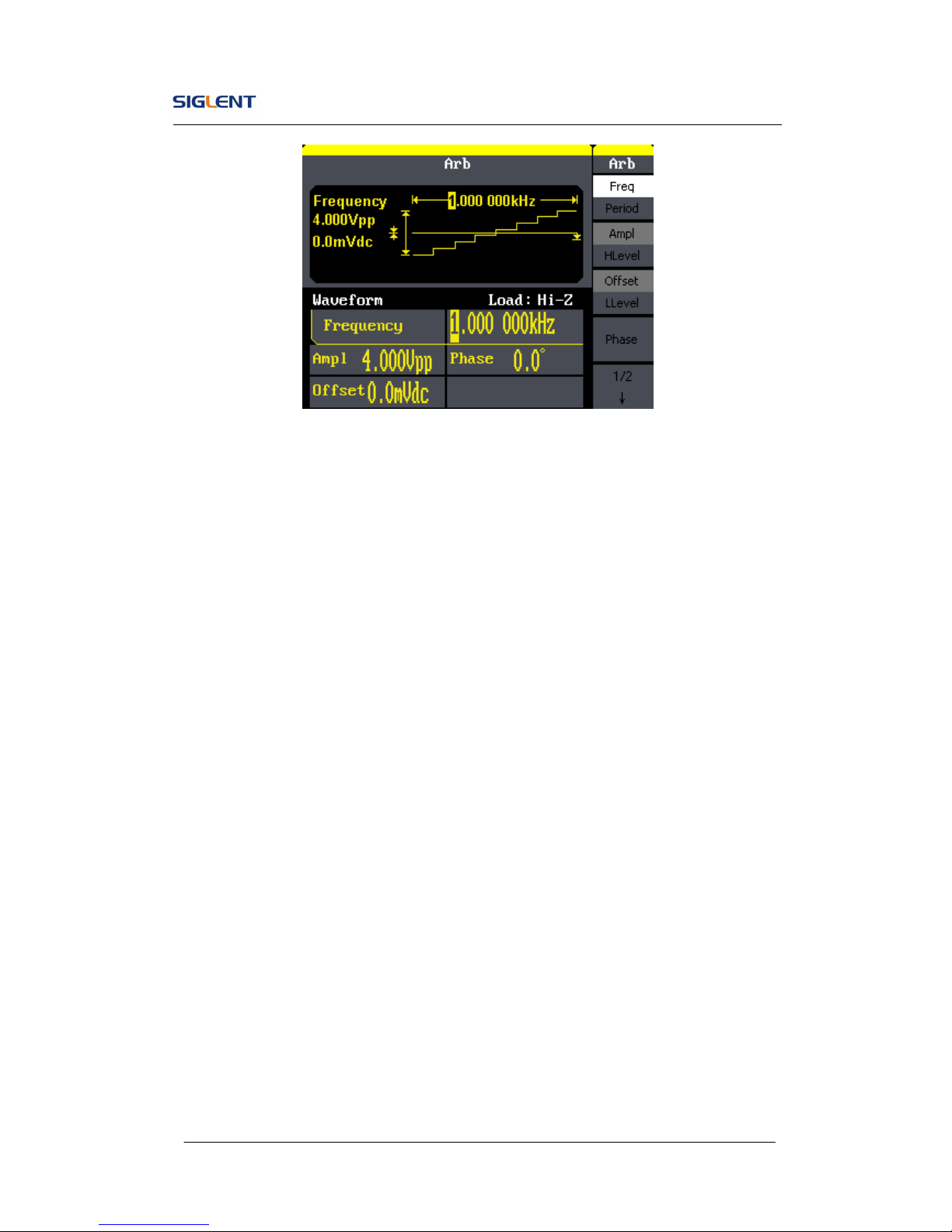
6. Press Arb button, and the waveform window displays arbitrary waveform.
SDG800 Series Generator can generate repeatable arbitrary waveform
signals with at most 16K points and 5MHz frequency.
SDG800 User Manual 11
Figure 1- 12 Arbitrary Waveform Signal Display Interface
As is shown in Figure 1- 12, the default signal parameters are: 1kHz
frequency, 4.0Vpp amplitude and 0mVdc offset.
SDG800 User Manual 12
1.5. To Set Modulate/Sweep/Burst
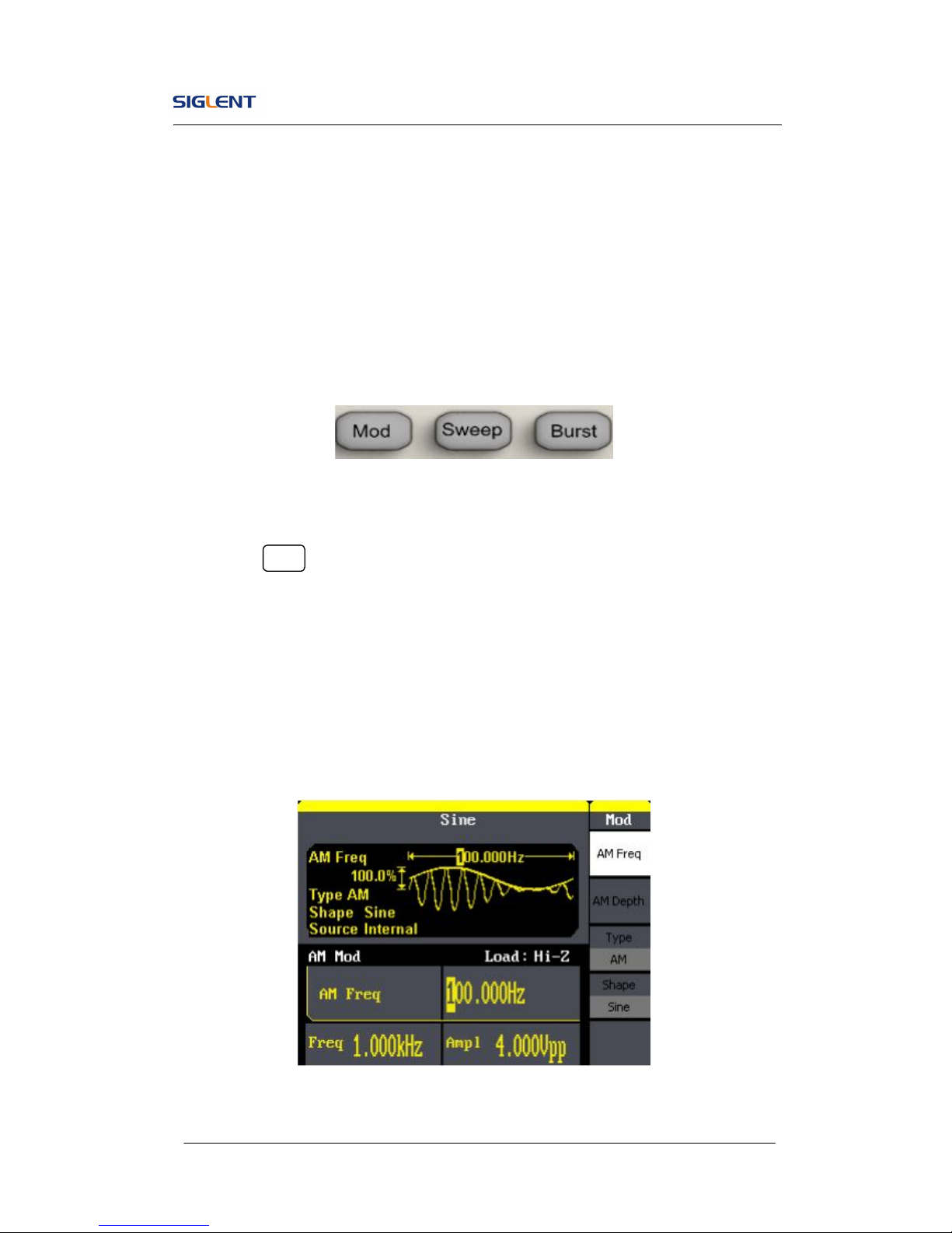
As shown in Figure 1- 13, there are three buttons on the front panel, which
are used for modulation, sweep and burst settings. The instructions below will
help you familiarize with the setting of these functions.
Figure 1- 13 Modulate/Sweep/Burst Button
1. Press Mod button, the modulated waveforms will be generated. The
modulated waveform can be changed by modifying the parameters such
as type, internal/external modulation, depth, frequency, waveform, etc.
SDG800 Series can modulate waveform using AM, FM, PM, ASK, FSK,
PWM and DSB-AM. Sine, square, ramp and arbitrary waveforms can be
modulated (pulse, noise and DC can not be modulated).
Figure 1- 14 Modulated Waveform Display Interface
SDG800 User Manual 13
2. Press Sweep button, sine, square, ramp or arbitrary waveform can be
swept (pulse, noise and DC can not be swept).
In the sweep mode, SDG800 Series generate signal with variable
frequencies.
Figure 1- 15 Sweep Waveform Display Interface
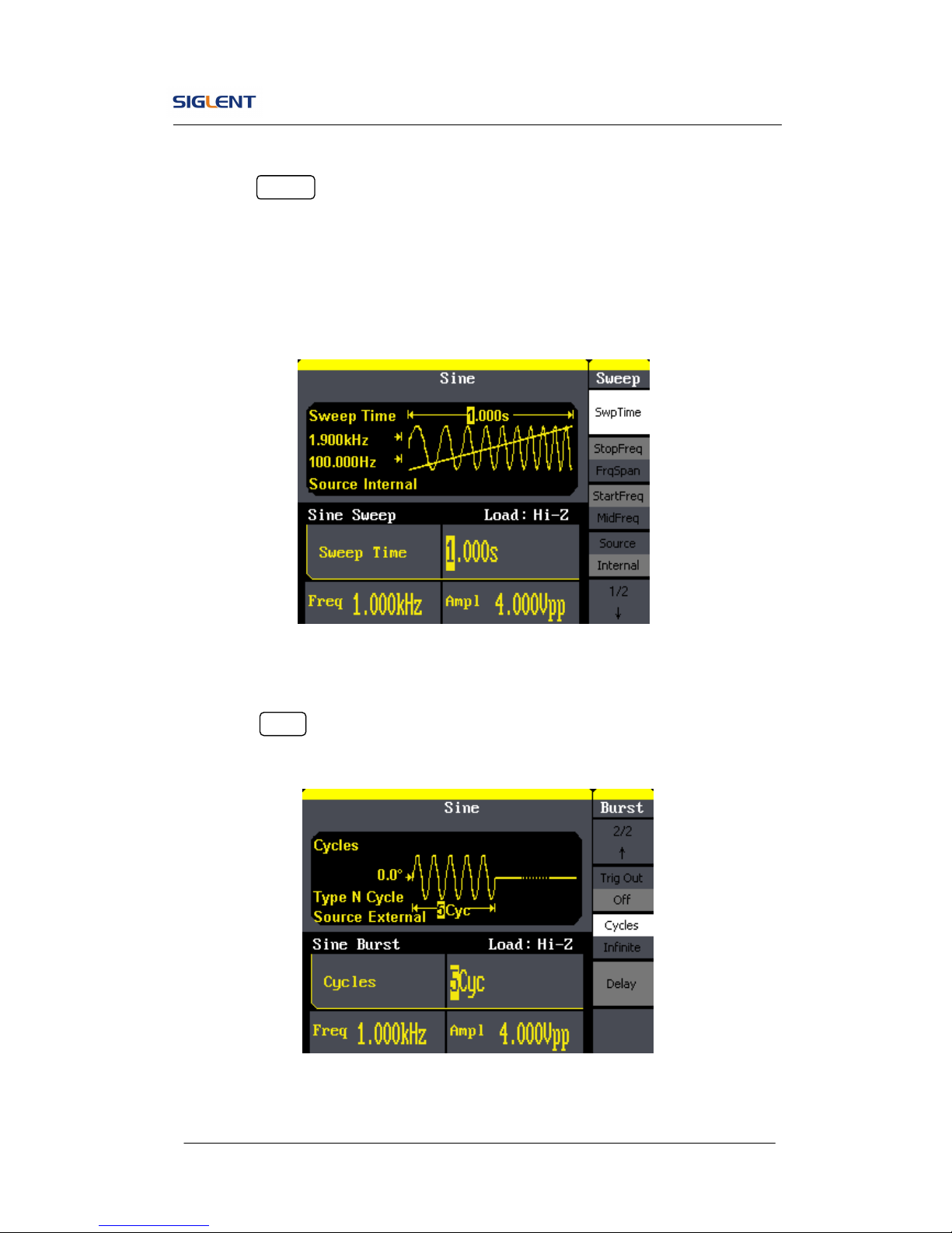
3. Press Burst button, burst for sine, square, ramp, pulse or arbitrary
waveform can be generated.
Figure 1- 16 Burst Waveform Display Interface
SDG800 User Manual 14
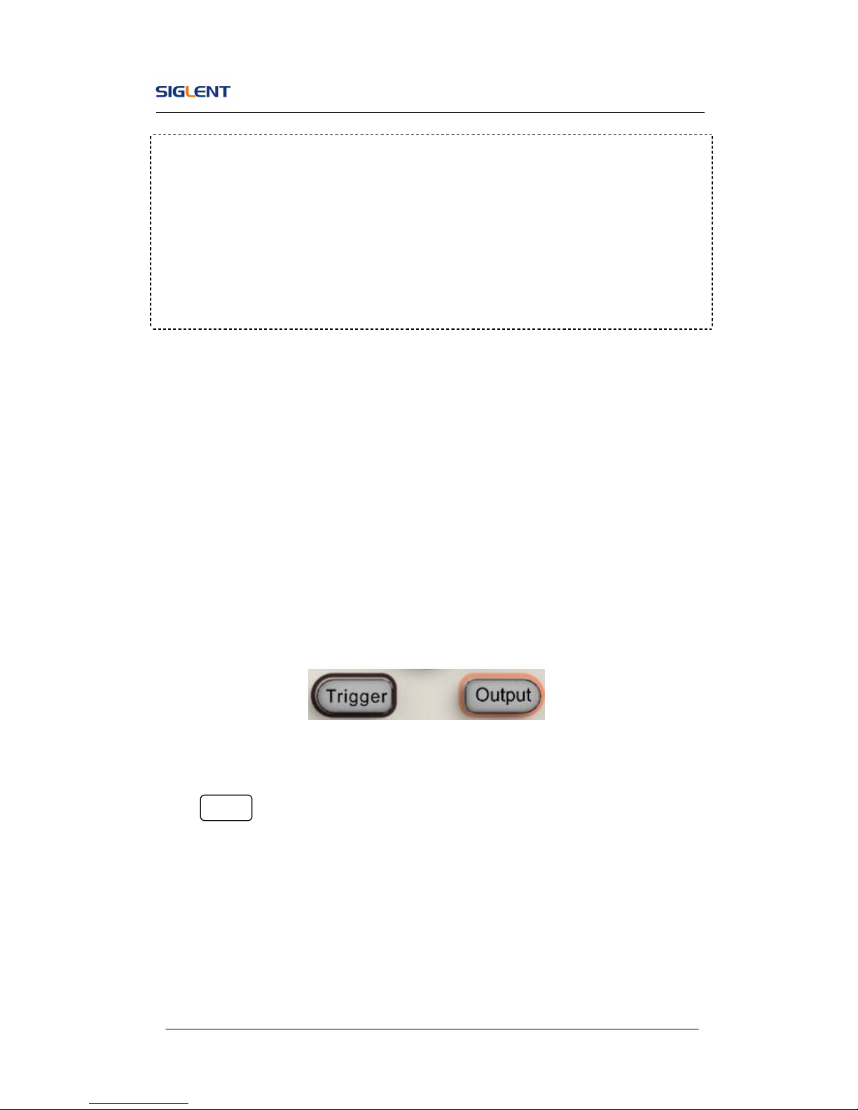
1.6. To Set Output
As is shown in Figure 1- 17, there are two buttons on the right side of the
operation panel, which are used to output/trigger control. The instruction
below will help you familiarize with these functions.
Figure 1- 17 Output Buttons
Press Output button, activate or deactivate the output signal.
Term Explanation
Burst: Output waveforms with set cycle times.
Burst can last for certain times of waveform cycle (N-Cycle Burst) or be
controlled by external gated signals (Gated Burst). Burst applies to all
kinds of waveforms, but noise can only be used in gated burst. Generally it
is called burst function within every signal generator.
SDG800 User Manual 15
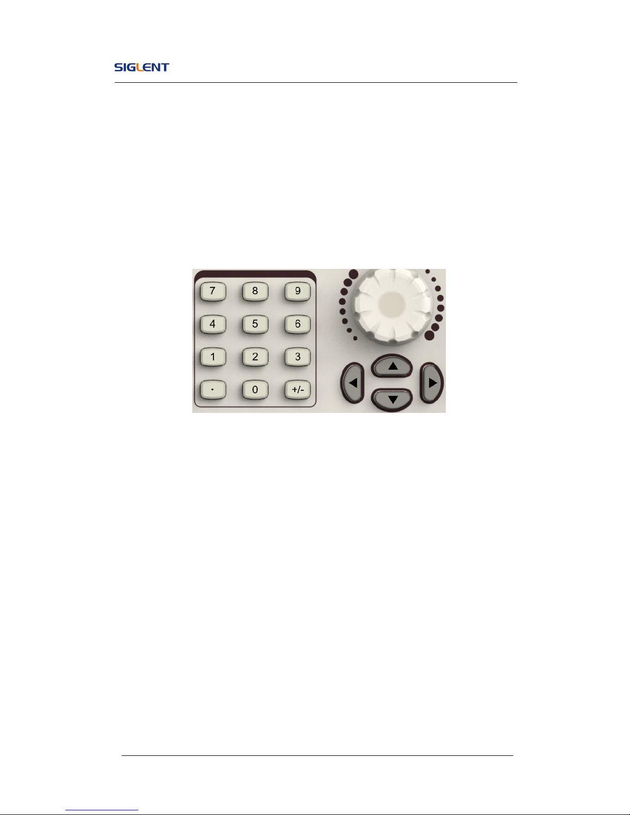
1.7. To Use Digital Input
As is shown in Figure 1- 18, there are three sets of buttons on the operation
panel, which are direction button, the knob and the keypad. The instruction
below will help you familiarize with the digital input function.
Figure 1- 18 Front Panel Digital Input
1. The up and down keys are used to shift parameters and the left and right
keys are used to shift digits.
2. Keypad is used to directly set the parameters value.
3. Knob is used to change a signal digit value whose range is 0~9.
SDG800 User Manual 16
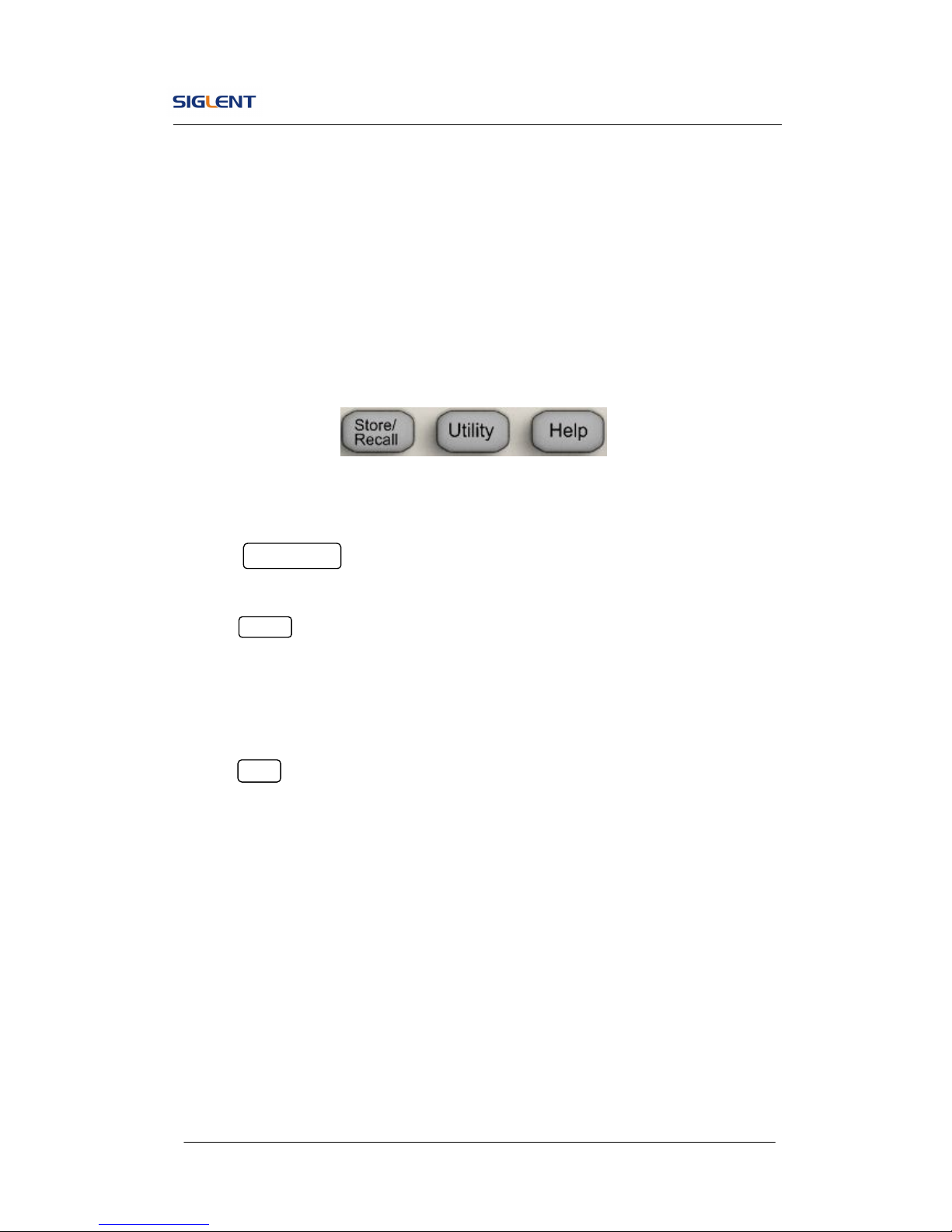
1.8. To Use Store/Utility/Help Function
As is shown in Figure 1- 19, there are three buttons on the operation panel,
which are used to call the store/recall, utility and help function. The instruction
below will help you familiarize with these functions.
Figure 1- 19 Store/Recall Utility and Help Button
1. The Store/Recall button is used to store waveform data and configure
information.
2. The Utility button is used to set the auxiliary system function, change
the output configure parameters, interface setting, system setting
information or perform the instrument self-test and read the calibration
information, etc.
3. The Help button is used to read the help information.
SDG800 User Manual 17
2. Operating Your Generator
Up to now you have got a brief understanding about SDG800 series with the
front/rear panel, every function control area and keys. You should also know
how to set your Function/Arbitrary Waveform Generator for your usage. If you
are not familiar with these operations, you are suggested to read chapter one
‘Getting Started’ again.
This chapter covers the following topics:
Setting Sine Signal
Setting Square Signal
Setting Ramp Signal
Setting Pulse Signal
Setting Noise Signal
Setting Arb Signal
Output Modulated Signal
Output Sweep Signal
Output Burst Signal
Store/Recall
Utility Setting
Help System
You are suggested to read this chapter carefully so as to understand
SDG800 Series Generator’s versatile waveform setting functions and
more operation methods.
SDG800 User Manual 18
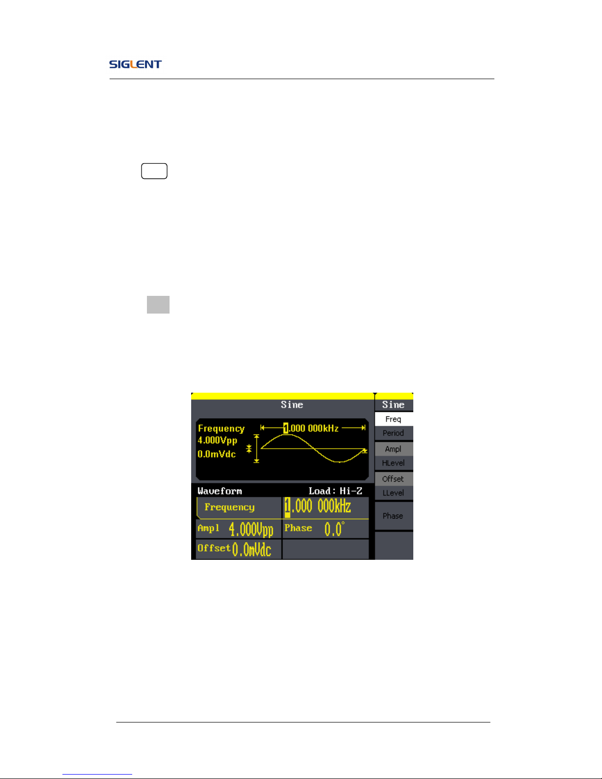
2.1. To Set Sine Signals
Press Sine button to call the sine operation. The sine waveform parameters
are set by using the sine operation menu.
The parameters of sine waveforms are: frequency/period, amplitude/high
level, offset/low level and phase. Different sine signals are generated by
setting these parameters. As is shown in Figure 2- 1, in the soft key menu,
select Freq. Cursor is located in the frequency parameter area in the
parameter display window, and users can set the frequency value here.
Figure 2- 1 Sine Parameter Display Interface
SDG800 User Manual 19
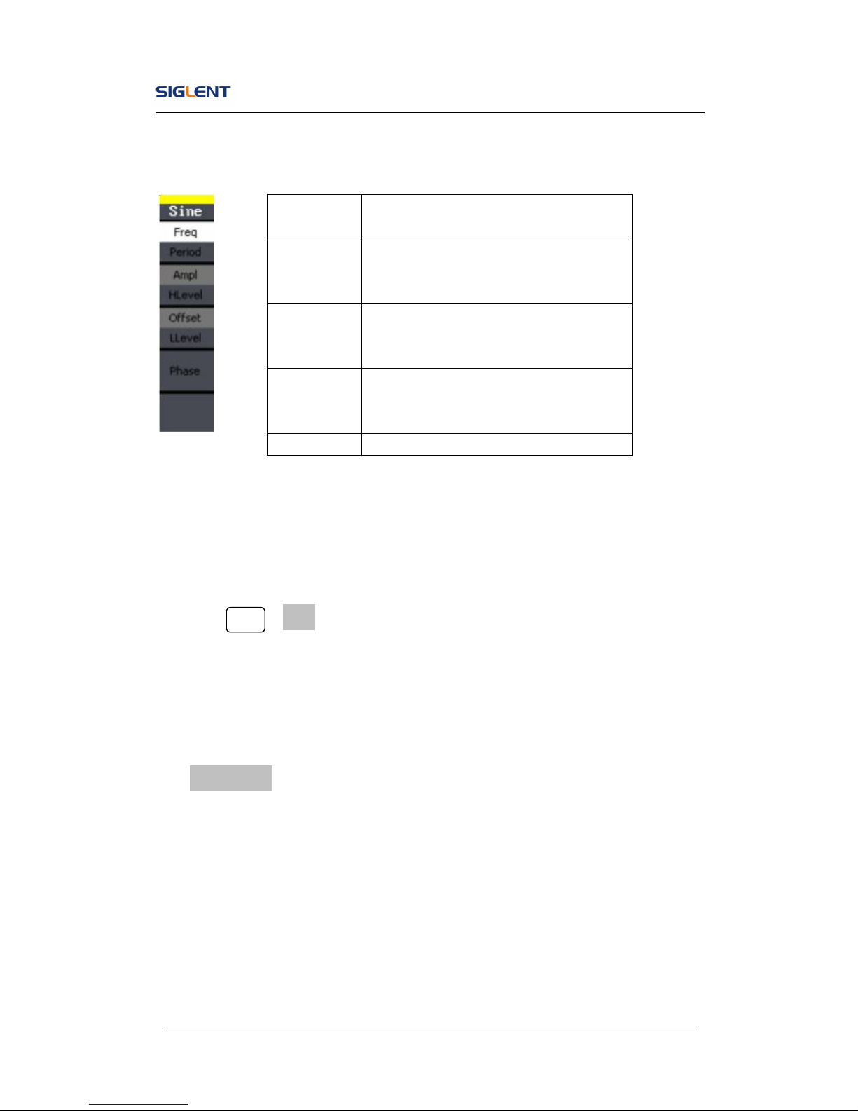
Figure 2- 2 Table2- 1 Menu Explanations of Sine Waveform
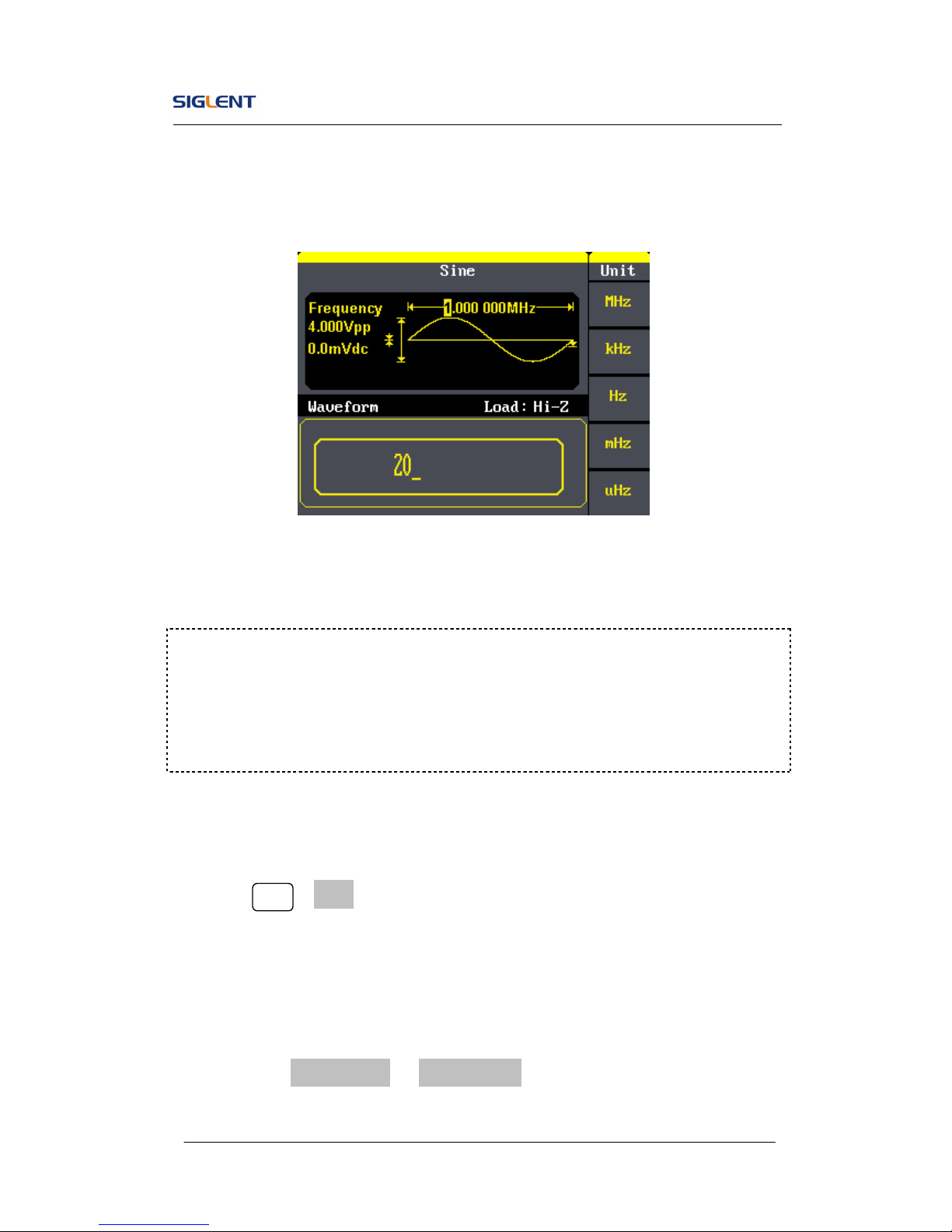
To Set the Output Frequency/Period
1. Press Sine →Freq, to set the frequency parameter.
The frequency shown on the screen when the instrument is powered is
the default value or the set value beforehand. When setting the function,
if the current value is valid for the new waveform, it will be used
sequentially. If you want to set the period for the waveform, press
Freq/Period button again, to switch to the period parameter (the current
operation is displayed in inverse color).
2. Input the desired frequency.
Use the keypad to input the parameter value directly, and press the
corresponding button to select the parameter unit. Or you can use the
direction button to select the digit you want to edit, and then use the knob
Function
menu
Explanations
Freq/
Period
Set the signal frequency or period;
The current parameter will be switched at
a second press.
Ampl/
HLevel
Set the signal amplitude or high level;
The current parameter will be switched at
a second press.
Offset/
LLevel
Set the signal offset or low level;
The current parameter will be switched at
a second press.
Phase Set the phase of the signal;
SDG800 User Manual 20
to change its value.
Figure 2- 3 Setting the Frequency
To Set the Output Amplitude
1. Press Sine →Ampl, to set the amplitude.
The amplitude shown on the screen when the instrument is powered is
the default value or the set value beforehand. When changing the
function, if the current value is valid for the new waveform, it will be used
sequentially. If you want to set the waveform by high level or low level,
press the Ampl/HLevel or Offset/LLevel button again, to switch into the
high level or low level parameter (the current operation is displayed in
Instruction:
When using the keypad to enter the digit, you can use the left direction button
to move the cursor backward and delete or change the value of the previous
digit.
 Loading...