

Page 1

SIGLENT
User Manual
SDG2000X Series Function/Arbitrary Waveform Generator
UM0202X-E02A
2017 SIGLENT TECHNOLOGIES CO., LTD
SDG2000X User Manual I
Page 2

SIGLENT
Declaration
Copyright © SIGLENT TECHNOLOGIES CO., LTD. All rights reserved.
Without permission, contents in this manual are not allowed to be copied,
extracted or translated.
II SDG2000X User Manual
Page 3

SIGLENT
General Safety Summary
Carefully read the following safety precautions to avoid any personal injuries
or damages to the instrument and any product connected to it. To avoid
potential hazards, please use the instrument as specified.
Only qualified technical personnel should service this instrument.
Avoid fire or open flame.
Use properly rated power line connections.
Use only the specified power line which has been approved by your local
regulatory agency.
Ground the Instrument.
The instrument is grounded through the protective ground conductor of the
power line. To avoid electric shock, the ground conductor must be connected
to the earth ground. Make sure the instrument is grounded correctly before
connecting its input or output terminals.
Connect the signal wire correctly.
The potential of the signal wire ground is equal to the earth, therefore do not
connect the signal wire to a high voltage. Do not touch the exposed contacts
or components.
Observe all terminal ratings.
To avoid fire or electric shock, please observe all ratings and sign instructions
on the instrument. Before connecting the instrument, please read the manual
carefully to gain more information about the ratings.
Do not operate with suspected failures.
If you suspect that the product is damaged, please let only qualified service
personnel check it.
Avoid circuit or wire exposure.
Do not touch exposed contacts or components when the power is on.
Do not operate in wet/damp conditions.
Do not operate in an explosive atmosphere.
Keep the surface of the instrument clean and dry.
SDG2000X User Manual III
Page 4
SIGLENT
Safety Terms and Symbols
Terms used on the instrument. Terms may appear on the instrument:
DANGER: Indicates an injury or hazard that may immediately happen.
WARNING: Indicates an injury or hazard that may not immediately happen.
CAUTION: Indicates that a potential damage to the instrument or other
property might occur.
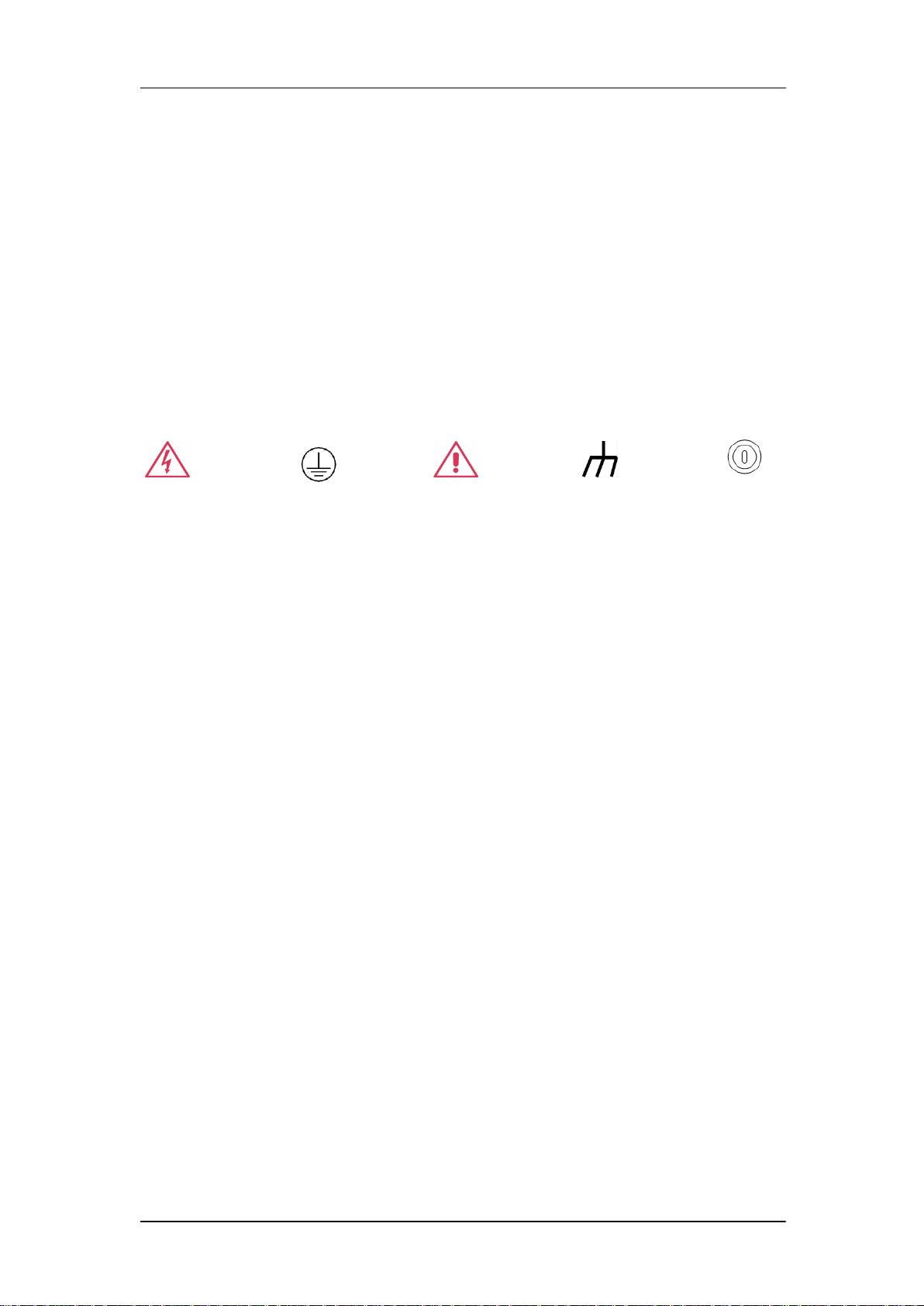
Symbols used on the instrument. Symbols may appear on the instrument:
Hazardous Protective Warning Chassis Power
Voltage Earth Ground Ground Switch
IV SDG2000X User Manual
Page 5

SIGLENT
Introduction of SDG2000X
The manual covers the following 3 models of SDG2000X Series
Function/Arbitrary Waveform Generators: SDG2042X, SDG2082X and
SDG2122X.
SIGLENT‘s SDG2000X is a series of dual-channel function/arbitrary waveform
generators with specifications of up to 120MHz maximum bandwidth,
1.2GSa/s sampling rate and 16-bit vertical resolution. The proprietary TrueArb
& EasyPulse techniques help to solve the weaknesses inherent in traditional
DDS generators when generating arbitrary, square and pulse waveforms.
Using these techniques the SDG2000X provides users with a variety of high
fidelity, low jitter signals in order to meet the growing requirements for a
multitude of complex applications.
Key Features
Dual-channel, 120MHz maximum bandwidth, 20Vpp maximum output
amplitude, output with 80dB dynamic range
High-performance sampling system with 1.2GSa/s sampling rate and
16-bit vertical resolution. No detail in your waveforms will be lost
Innovative TrueArb technology, based on a point-by-point architecture,
supports any 8pts~8Mpts Arb waveform with a sampling rate in range of
1μSa/s~75MSa/s
Innovative Easy Pulse technology, capable of generating lower jitter
Square or Pulse waveforms, brings a wide range and extremely high
precision in pulse width and rise/fall times adjustment
A variety of analog and digital modulation types: AM、DSB-AM、FM、PM、
FSK、ASK 、PSK and PWM
Sweep and Burst functions
SDG2000X User Manual V
Page 6

SIGLENT
Harmonic waveforms generating function
Waveforms combining function
High precision Frequency Counter
196 kinds of built-in arbitrary waveforms
Standard interfaces: USB Host, USB Device(USBTMC), LAN(VXI-11)
Optional interface: GPIB
4.3‖ touch screen display for easier operation
VI SDG2000X User Manual
Page 7

SIGLENT
Catalog
General Safety Summary ............................................................................... III
Introduction of SDG2000X ............................................................................. V
1 Quick Start ................................................................................................ 1
1.1 Handle Adjustment ....................................................................... 2
1.2 The Front/Rear Panel ................................................................... 3
1.3 To Select a Waveform ................................................................... 8
1.4 To Set Modulation/Sweep/Burst.................................................. 12
1.5 To Turn On/Off Output ................................................................ 14
1.6 To Use Numeric Input ................................................................. 15
1.7 To Use Common Function Keys ................................................. 16
2 Front Panel Operations ........................................................................... 17
2.1 To Set Sine Waveform ................................................................ 18
2.2 To Set Square Waveform ............................................................ 23
2.3 To Set Ramp Waveform .............................................................. 26
2.4 To Set Pulse Waveform .............................................................. 28
2.5 To Set Noise Waveform .............................................................. 32
2.6 To Set DC Waveform .................................................................. 36
2.7 To Set Arbitrary Waveform .......................................................... 37
2.8 To Set Harmonic Function .......................................................... 48
2.9 To Set Modulation Function ........................................................ 51
2.9.1 AM ........................................................................................ 52
2.9.2 DSB-AM ............................................................................... 55
2.9.3 FM ........................................................................................ 57
2.9.4 PM ........................................................................................ 59
2.9.5 FSK ...................................................................................... 61
2.9.6 ASK ...................................................................................... 63
2.9.7 PSK ...................................................................................... 64
2.9.8 PWM .................................................................................... 66
2.10 To Set Sweep Function ............................................................... 69
2.11 To Set Burst Function ................................................................. 74
2.12 To Store and Recall .................................................................... 80
2.12.1 Storage System ............................................................. 81
SDG2000X User Manual VII
Page 8

SIGLENT
2.12.2 File Type ........................................................................ 82
2.12.3 File Operation ................................................................ 84
2.13 To Set Utility Function ................................................................. 88
2.13.1 System Settings ............................................................. 90
2.13.2 Test/Cal .......................................................................... 98
2.13.3 Frequency Counter ...................................................... 103
2.13.4 Output .......................................................................... 106
2.13.5 CH Copy/Coupling ....................................................... 109
2.13.6 Remote Interface ......................................................... 114
2.13.7 Sync Output ................................................................. 120
2.13.8 Clock Source ................................................................ 122
2.13.9 Mode ............................................................................ 123
2.13.10 Overvoltage Protection................................................. 125
3 Examples .............................................................................................. 126
3.1 Example 1: Generate a Sine Waveform ................................... 127
3.2 Example 2: Generate a Square Waveform ............................... 129
3.3 Example 3: Generate a Ramp Waveform ................................. 131
3.4 Example 4: Generate a Pulse Waveform .................................. 133
3.5 Example 5: Generate a Noise .................................................. 135
3.6 Example 6: Generate a DC Waveform ..................................... 136
3.7 Example7: Generate a Linear Sweep Waveform ...................... 137
3.8 Example 8: Generate a Burst Waveform .................................. 139
3.9 Example 9: Generate an AM Modulation Waveform ................. 141
3.10 Example 10: Generate a FM Modulation Waveform ................. 143
3.11 Example 11: Generate a PM Modulation Waveform ........... 145
3.12 Example 12: Generate a FSK Modulation Waveform ......... 147
3.13 Example 13: Generate an ASK Modulation Waveform ............. 149
3.14 Example 14: Generate a PSK Modulation Waveform ............... 151
3.15 Example 15: Generate a PWM Modulation Waveform ............. 153
3.16 Example 16: Generate a DSB-AM Modulation Waveform ........ 155
4 Troubleshooting .................................................................................... 157
4.1 General Inspecting ................................................................... 157
4.2 Troubleshooting ........................................................................ 158
5 Service and Support ............................................................................. 159
VIII SDG2000X User Manual
Page 9

SIGLENT
5.1 Maintenance summary ............................................................. 159
5.2 Contact SIGLENT ..................................................................... 160
6 Appendix ............................................................................................... 161
Appendix A: Accessories ...................................................................... 161
Appendix B: Daily Maintenance and Cleaning ..................................... 162
SDG2000X User Manual IX
Page 10

Page 11

1 Quick Start
This chapter covers the following topics:
Handle Adjustment
The Front/Rear Panel
To Select a Waveform
To Set Modulation/Sweep/Burst
To Turn On/Off Output
To Use Numeric Input
SIGLENT
To Use Common Function Keys
SDG2000X User Manual 1
Page 12

SIGLENT
1.1 Handle Adjustment
To adjust the handle position of SDG2000X, please grip the handle by the
sides and pull it outward. Then, make the handle rotate to the desired position.
Figure 1-1 Viewing Position and Carrying Position
2 SDG2000X User Manual
Page 13
SIGLENT
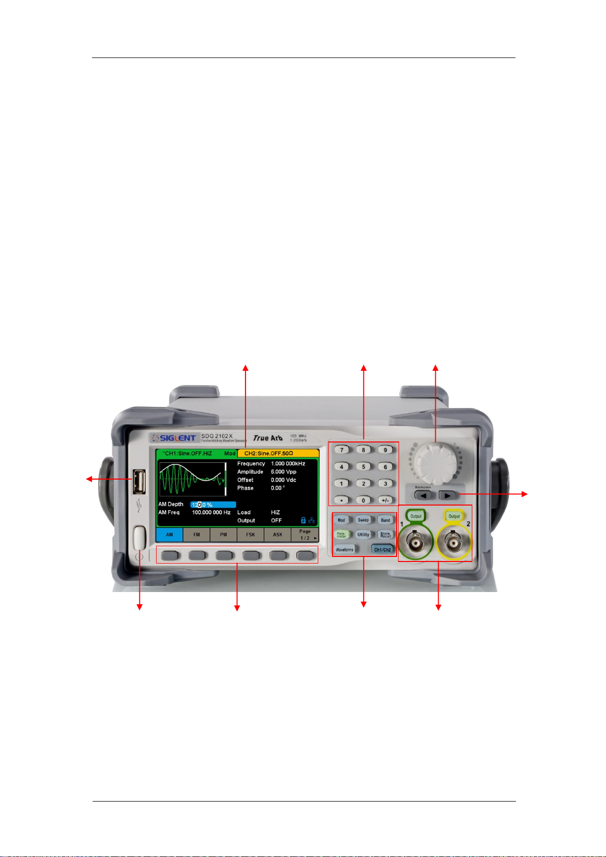
USB
Host
Numeric Keyboard
Power
Key
User Interface
Menu
Softkeys
Function
Keys
Channel
Control
Arrow
Keys
1.2 The Front/Rear Panel
This chapter will provide a brief introduction and description for the operation
and functions of the front/rear panel.
Front Panel
SDG2000X has a clear and simple front panel which includes 4.3 inch touch
screen, menu softkeys, numeric keyboard, knob, function keys, arrow keys,
and channel control area, etc.
Figure 1-2 Front Panel of SDG2000X
SDG2000X User Manual 3
Page 14
SIGLENT
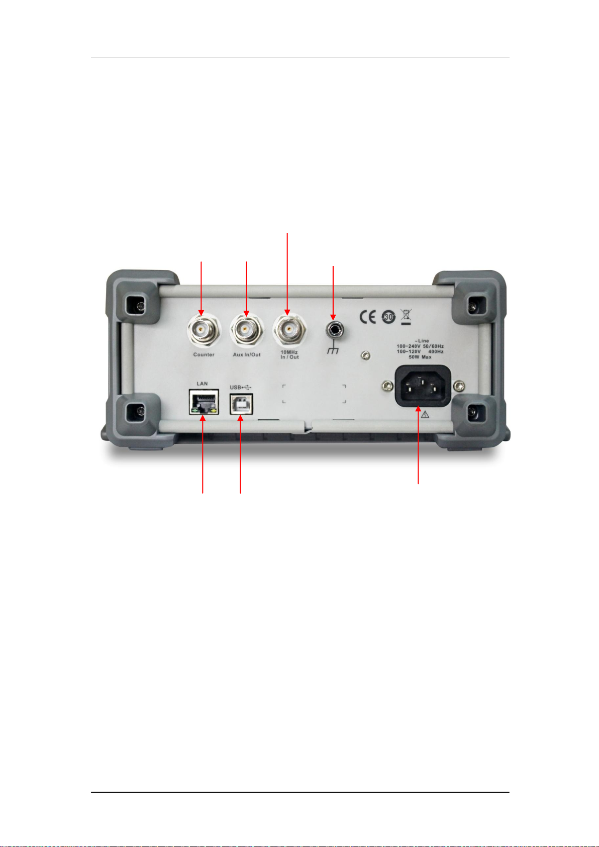
Aux
In/Out
10 MHz Clock Input/Output
Earth Terminal
LAN Interface
USB Device
AC Power Supply
Input
Counter
Rear Panel
The rear panel provides multiple interfaces, including Counter, 10MHz In/Out,
Aux In/Out, LAN, USB Device, Earth Terminal and AC Power Supply Input.
Figure 1-3 Rear Panel of SDG2000X
4 SDG2000X User Manual
Page 15
SIGLENT
1 2
4 3 8 7 6 5
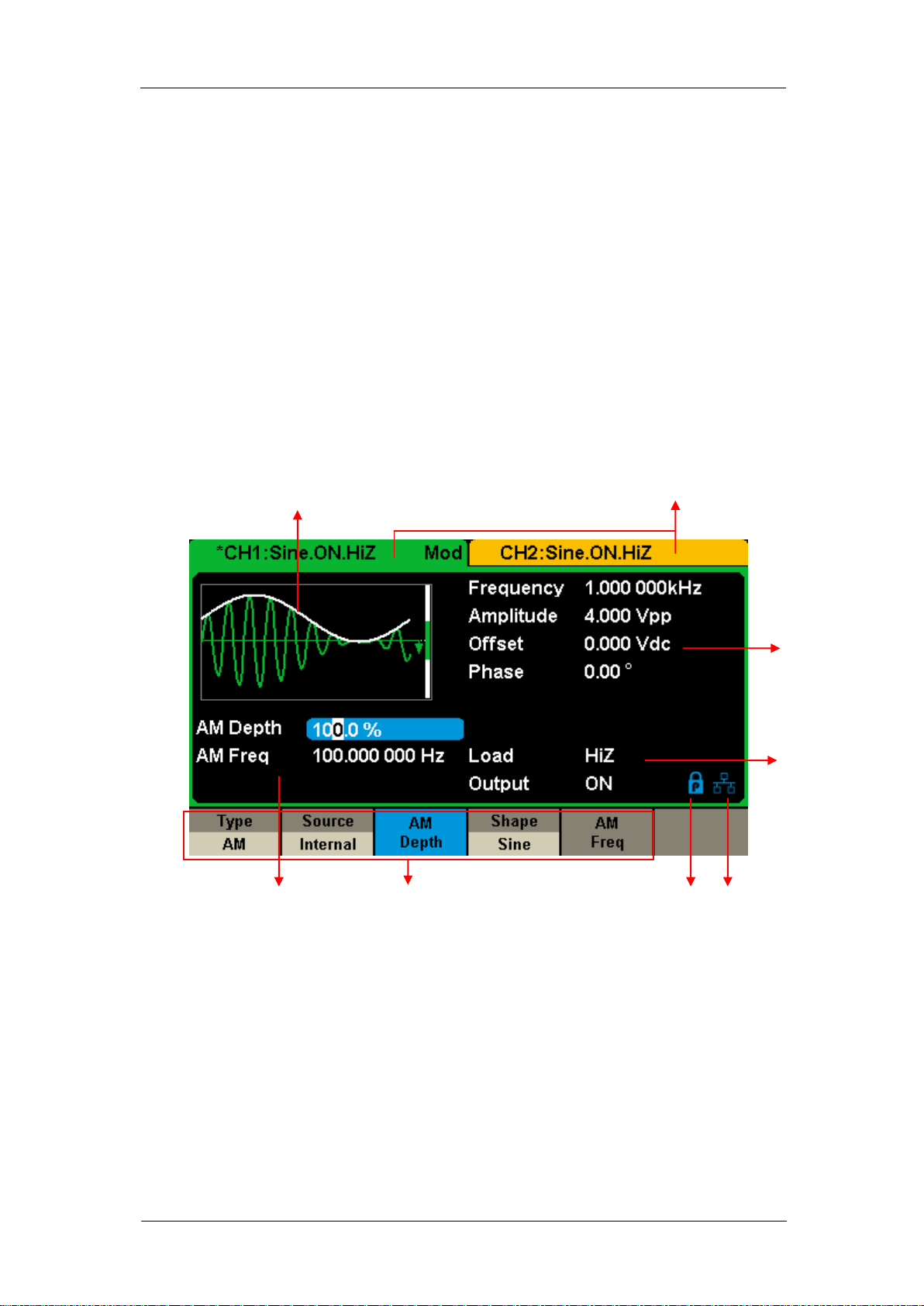
Touch Screen Display
SDG2000X can only display parameters and waveform of one channel at a
time. The picture below shows the interface when CH1 chooses AM
modulation of sine waveform. The information displayed may vary depending
on the function selected.
The entire screen of the SDG2000X is a touch screen. You can use your figure
or touch pen to control the instrument. Most functions and selections can be
chosen using the touch screen in a similar manner to the front panel keys and
knob.
Figure 1-4 Touch Screen Display
1. Waveform Display Area
Displays the currently selected waveform of each channel.
2. Channel Status Bar
Indicates the selected status and output configuration of the channels.
SDG2000X User Manual 5
Page 16
SIGLENT
3. Basic Waveform Parameters Area
Shows the current waveform‘s parameters of each channel. Press Parameter
and select the corresponding softkey to highlight the parameter to configure.
Then use number keys or knob to change the parameter value.
4. Channel Parameters Area
Displays the load and output settings of the currently selected channel.
Load ----Value of the output load, as selected by the user.
Press Utility → Output → Load, then use the softkeys, number keys or knob to
change the parameter value; or continue pressing the corresponding output
key for two second to switch between High Impedance and 50Ω.
High Impedance: display HiZ.
Load: display impedance value (the default is 50Ω and the range is 50Ω to
100kΩ).
Note: This setting does not actually change the instrument‘s output impedance
of 50Ω but rather is used to maintain amplitude accuracy into different load
values.
Output ----Channel output state.
After pressing corresponding channel output control port, the current channel
can be turned on/off.
5. LAN Status Icon
SDG2000X will show different prompt messages based on the current network
status.
This mark indicates LAN connection is successful.
This mark indicates there is no LAN connection or LAN connection is
unsuccessful.
6. Mode Icon
SDG2000X will show different prompt messages based on the current mode.
This mark indicates current mode is Phase-locked.
6 SDG2000X User Manual
Page 17

SIGLENT
This mark indicates current mode is Independent.
7. Menu
Shows the menu corresponding to the displayed function. For example, Figure
1-4 Touch Screen Display shows the parameters of ―AM modulation‖.
8. Modulation Parameters Area
Shows the parameters of the current modulation function. After selecting the
corresponding menu, use number keys or knob to change the parameter
value.
SDG2000X User Manual 7
Page 18
SIGLENT
1.3 To Select a Waveform
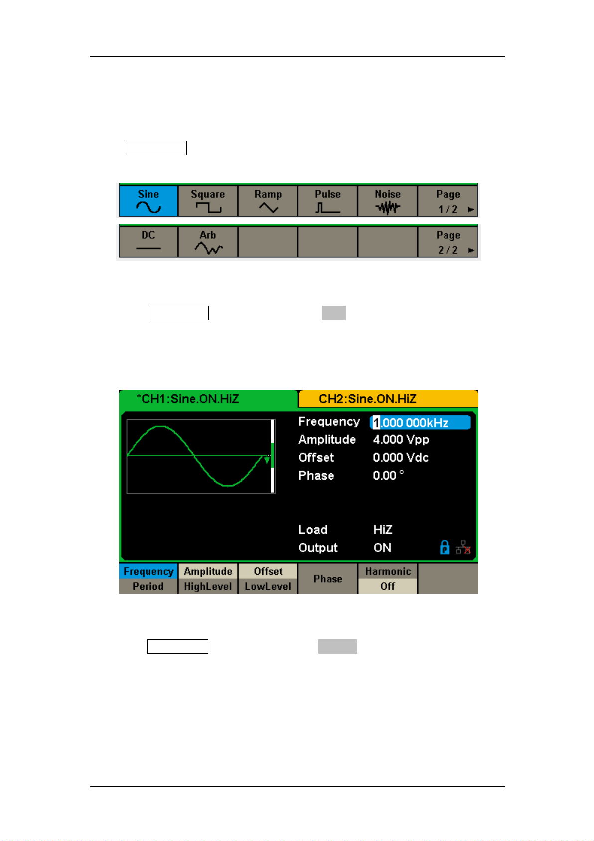
Press Waveforms to enter the menu as Figure 1-5 shows. The example below
will help familiarize with the waveform selection settings.
Figure 1-5 Waveform Selections
1. Press Waveforms key and then press Sine softkey. The SDG2000X can
generate sine waveforms with frequencies from 1μHz to 120MHz. By
setting Frequency/Period, Amplitude/High level, Offset/Low level and
Phase, a sine signal with different parameters can be generated.
Figure 1-6 Sine Display Interface
2. Press Waveforms key and then press Square softkey. The generator can
generate square waveforms with frequencies from 1μHz to 25MHz and
variable duty cycle. By setting Frequency/Period, Amplitude/High level,
Offset/Low level, Phase and DutyCycle, a square waveform with different
parameters can be generated.
8 SDG2000X User Manual
Page 19

SIGLENT
Figure 1-7 Square Display Interface
3. Press Waveforms key and then press Ramp softkey. The generator can
generate ramp waveforms with frequencies from 1μHz to 1MHz and
variable symmetry. By setting Frequency/Period, Amplitude/High level,
Offset/Low level, Phase and Symmetry, a ramp waveform with different
parameters can be generated.
Figure 1-8 Ramp Display Interface
4. Press Waveforms key and then press Pulse softkey. The generator can
generate pulse waveforms with frequencies from 1μHz to 25 MHz and
variable pulse width and rise/fall times. By setting Frequency/Period,
Amplitude/High level, Offset/Low level, PulWidth/Duty, Rise/Fall and Delay,
SDG2000X User Manual 9
Page 20
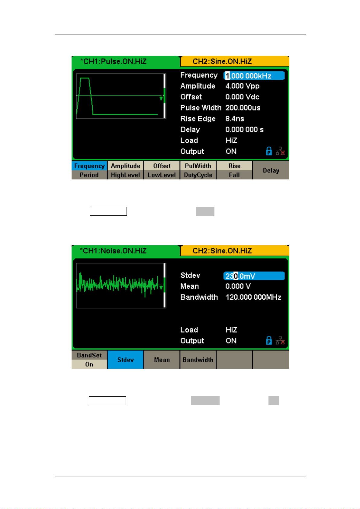
a pulse waveform with different parameters can be generated.
Figure 1-9 Pulse Display Interface
SIGLENT
5. Press Waveforms key and then press Noise softkey. The generator can
generate noise with bandwidth from 20MHz to 120MHz. By setting Stdev
and Mean, noise with different parameters can be generated.
Figure 1-10 Noise Display Interface
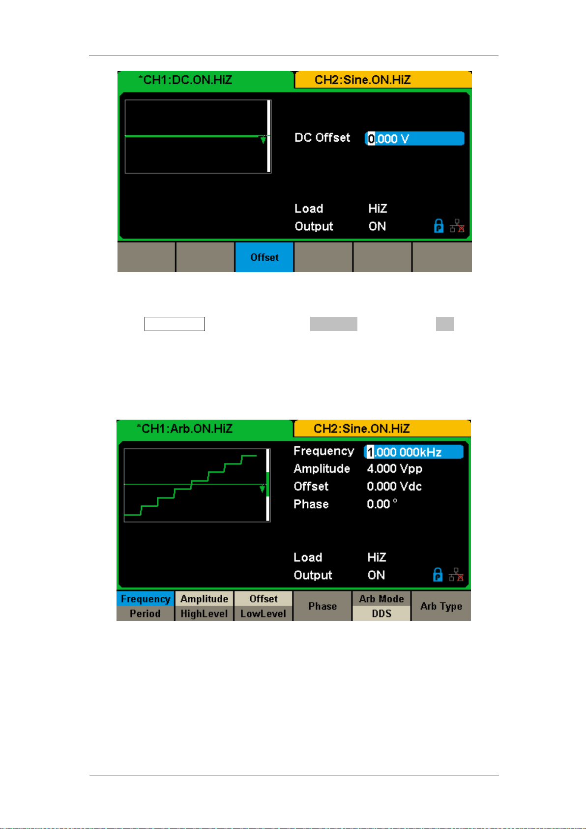
6. Press Waveforms key and then press Page 1/2, last press the DC softkey.
The generator can generate a DC signal with a level up to ±10V into a
HighZ load or ±5V into a 50Ω load.
10 SDG2000X User Manual
Page 21
SIGLENT
Figure 1-11 DC Display Interface
7. Press Waveforms key and then press Page 1/2, last press the Arb softkey.
The generator can generate repeatable arbitrary waveforms with length
from 8 to 8M points and frequencies up to 20MHz. By setting
Frequency/Period, Amplitude/High level, Offset/Low level, Phase and Arb
Mode, an arbitrary signal with different parameters can be generated.
Figure 1-12 Arbitrary Waveform Display Interface
SDG2000X User Manual 11
Page 22
SIGLENT
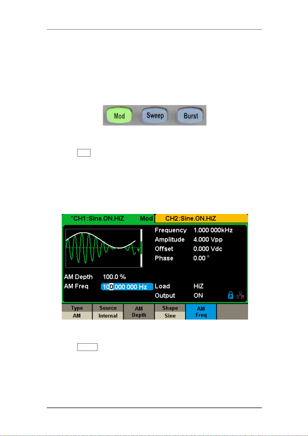
1.4 To Set Modulation/Sweep/Burst
As shown in Figure 1-13, there are three keys on the front panel which are
used for modulation, sweep and burst settings. The instructions below will help
to explain these functions.
Figure 1-13 Modulate/Sweep/Burst Key
1. Press Mod, the Modulation function will be enabled.
The modulated waveform can be changed by modifying the parameters such
as Type, Source, AM Depth, AM Freq, Shape, etc. The SDG2000X can
modulate waveforms using AM, FM, PM, ASK, FSK, PSK, PWM and DSB-AM,
etc. Pulse waveforms can only be modulated using PWM. Noise and DC
waveforms cannot be modulated.
Figure 1-14 Modulation Display Interface
2. Press Sweep, the Sweep function will be enabled.
Sine, square, ramp and arbitrary waveforms support the sweep function. In
sweep mode, the SDG2000X can generate signals with variable frequency.
The available range of sweep time is from 1ms to 500s. The trigger source can
be ―Internal‖, ―External‖ or ―Manual‖.
12 SDG2000X User Manual
Page 23
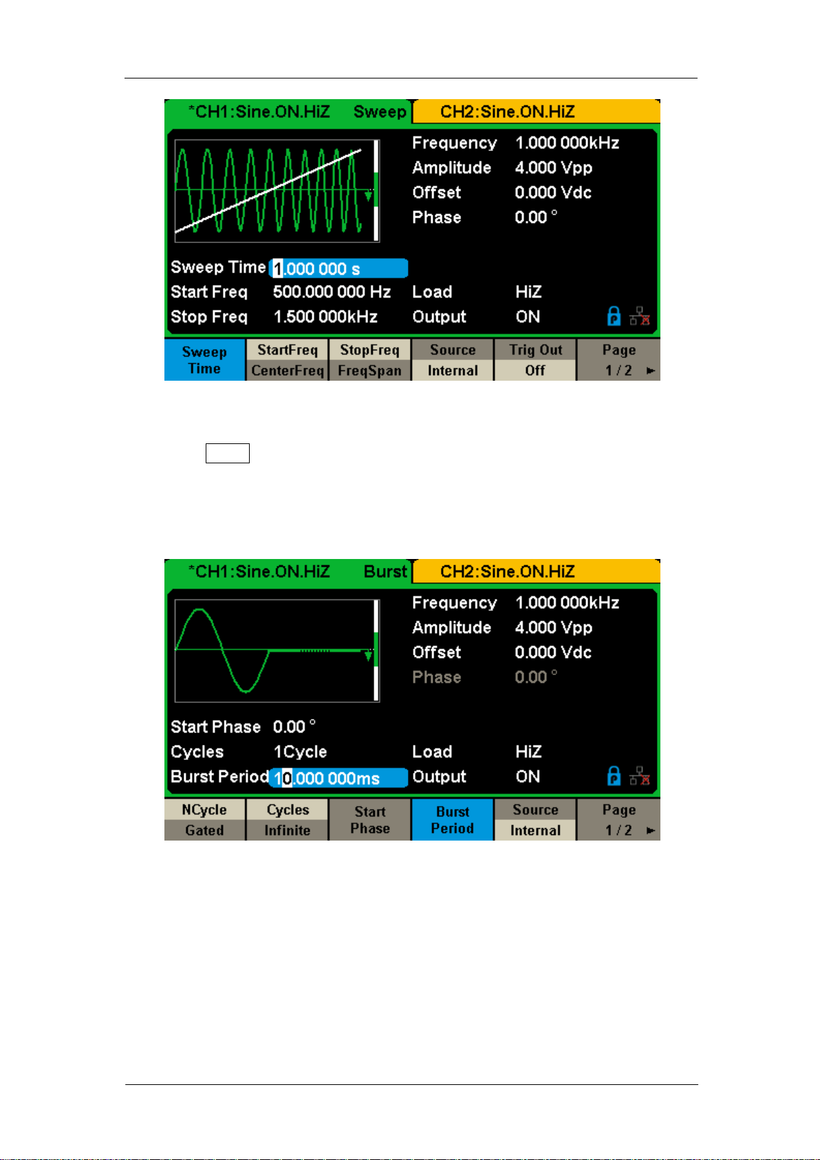
Figure 1-15 Sweep Waveform Display Interface
3. Press Burst, the Burst function will be enabled.
SIGLENT
Burst signals for sine, square, ramp, pulse or arbitrary waveforms may be
generated. Start Phase ranges from 0° to 360° and Burst Period ranges from
1μs to 1000s.
Figure 1-16 Burst Waveform Display Interface
SDG2000X User Manual 13
Page 24
SIGLENT
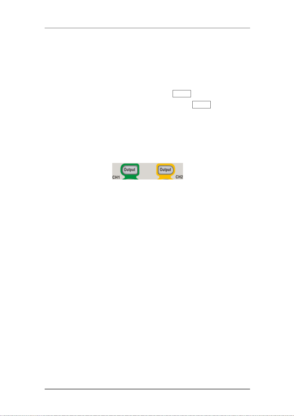
1.5 To Turn On/Off Output
As shown in Figure 1-17 there are two keys on the right side of the operation
panel which are used to enable / disable the output of the two channels.
Choose a channel and press the corresponding Output key, the key backlight
will be lighted and the output will be enabled. Press the Output key again, the
key backlight will be extinguished and the output will be disabled.
Keep pressing the corresponding output key for two seconds to switch
between High Impedance and 50Ω load.
Figure 1-17 Output Keys
14 SDG2000X User Manual
Page 25
SIGLENT
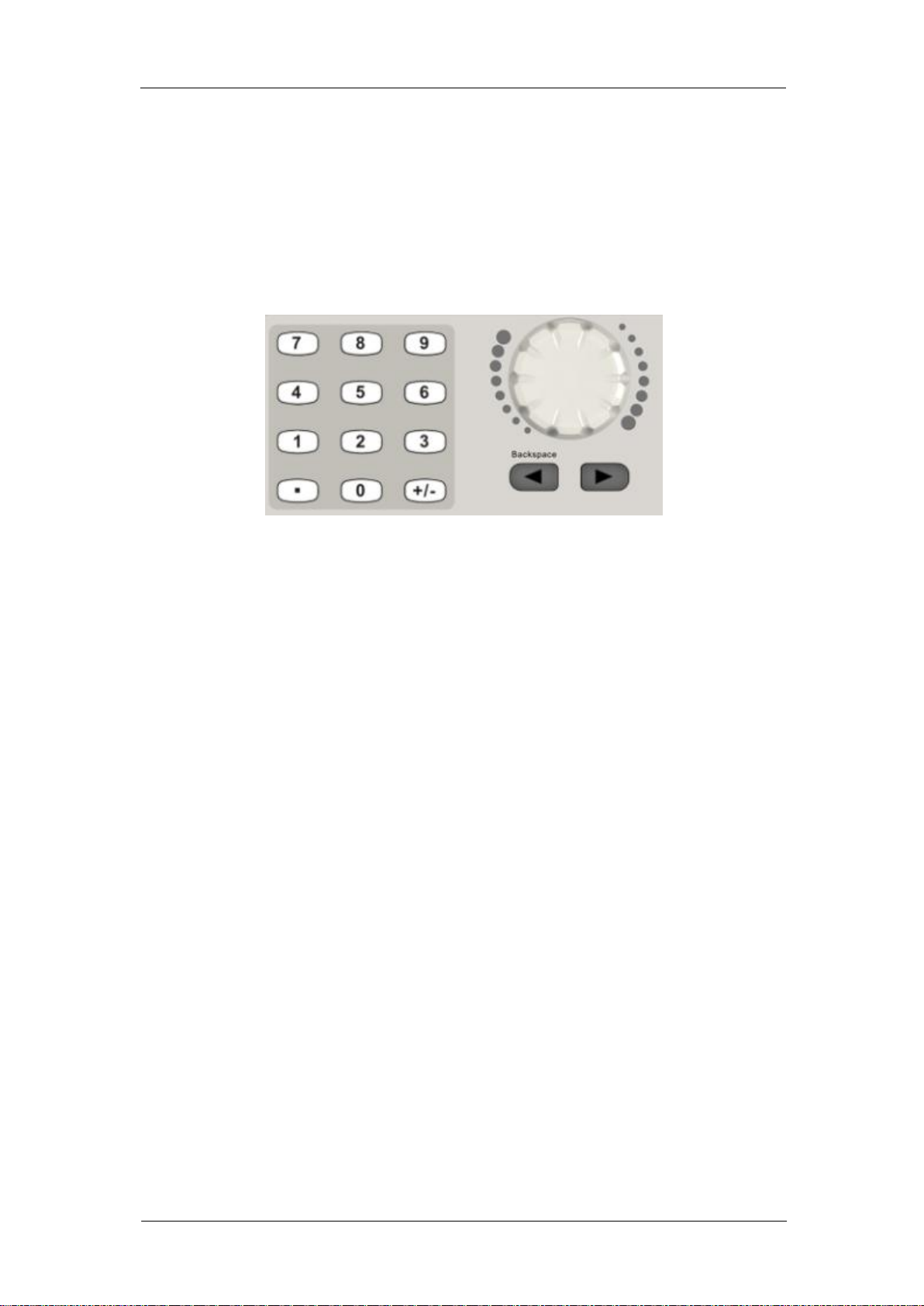
1.6 To Use Numeric Input
As shown in Figure 1-18, there are three sets of keys on the front panel, which
are arrow keys, knob and numeric keyboard. The instructions below will help
to familiarize you with the digital input selection.
Figure 1-18 Front Panel Digital Input
1. The numeric keyboard is used to enter the parameter‘s value.
2. The knob is used to increase (clockwise) or decrease (counterclockwise)
the current digit when setting parameters
3. When using knob to set parameters, the arrow keys are used to select the
digit to be modified; When using numeric keyboard to set parameters, the
left arrow key is used as a Backspace function.
SDG2000X User Manual 15
Page 26

SIGLENT
1.7 To Use Common Function Keys
As shown in Figure 1-19, there are five keys on the operation panel, which are
labeled Parameter, Utility, Store/Recall, Waveforms, and Ch1/Ch2. The
instructions below will help to familiarize you with these functions.
Figure 1-19 Waveforms Utility and Parameter Key
1. The Parameter key makes it convenient for the operator to set the
parameters of basic waveforms directly.
2. The Utility key is used to set the auxiliary system function, such as output
configurations, interface setting, system setting information, performing
the instrument self-test and reading the calibration information, etc.
3. The Store/Recall key is used to store and recall waveform data and
configuration information.
4. The Waveforms key is used to select basic waveforms.
5. The Ch1/Ch2 key is used to switch the currently selected channel
between CH1 and CH2. After start-up, CH1 is selected as default. At this
point, press the key to select CH2.
16 SDG2000X User Manual
Page 27

SIGLENT
2 Front Panel Operations
Up to now, you have got a brief understanding about SDG2000X with the
front/rear panel, every function control area and keys. You should also know
how to set your Function/Arbitrary Waveform Generator for your usage. If you
are not familiar with these operations, you are suggested to read chapter one
‗Quick Start‘ again.
This chapter covers the following topics:
To Set Sine
To Set Square
To Set Ramp
To Set Pulse
To Set Noise
To Set DC
To Set Arbitrary
To Set Harmonic Function
To Set Modulation Function
To Set Sweep Function
To Set Burst Function
To Store and Recall
To Set Utility Function
It is recommended that you read this chapter carefully so as to understand the
SDG2000X‘s versatile waveform setting functions and additional operation
methods.
SDG2000X User Manual 17
Page 28
SIGLENT
FuS
e
Explanations
Frequency/
Period
Set the signal frequency or period;
The current parameter will be switched at a second press.
Amplitude/
HighLevel
Set the signal amplitude or high level;
The current parameter will be switched at a second press.
Offset/
LowLevel
Set the signal offset or low level;
The current parameter will be switched at a second press.
Phase
Set the phase of the signal.
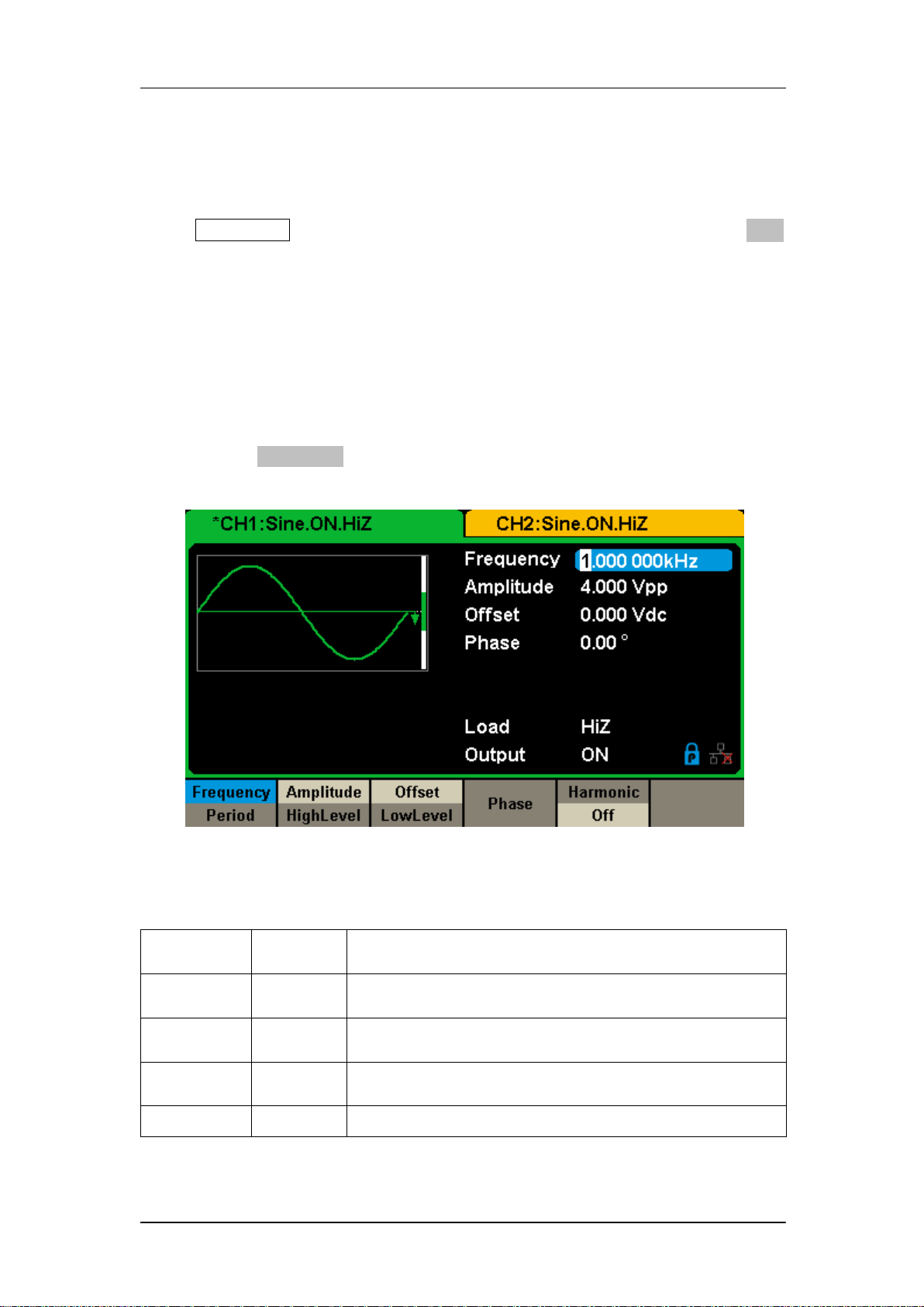
2.1 To Set Sine Waveform
Press Waveforms key to select the waveform function and then press the Sine
softkey. The sine waveform parameters are set by using the sine operation
menu.
The parameters available for sine waveforms include frequency/period,
amplitude/high level, offset/low level and phase. Different sine signals can be
generated by setting these parameters. As shown in Figure 2-1, in the soft key
menu, select Frequency. The frequency parameter area is highlighted in the
parameter display window, and users can set the frequency value here.
Figure 2-1 Sine Parameters Display Interface
Table 2-1 Menu Explanations of Sine Waveform
18 SDG2000X User Manual
Page 29
SIGLENT
To Set the Frequency/Period
Frequency is one of the most important parameters of basic waveforms. For
different instrument models and waveforms, the available ranges of frequency
are different. For detailed information, please refer to ―SDG2000X Datasheet‖.
The default frequency is 1kHz.
1. Press Waveforms → Sine → Frequency, to set the frequency parameter.
The frequency shown on the screen when the instrument is powered on is the
default value or the set value of last power down. If Period (rather than
Frequency) is the desired parameter, press Frequency/Period again to enter
the Period mode. The current value for the waveform‘s period is now
displayed in inverse color. Press the Frequency/Period key once again to
return to the Frequency entry mode.
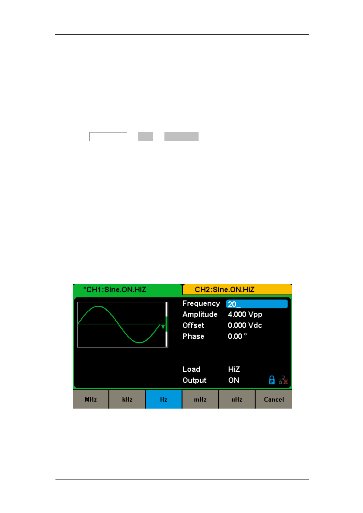
2. Input the desired frequency.
Use the numeric keyboard to input the parameter value directly, and press the
corresponding key to select the parameter unit. Or use the arrow keys to
select the digit to edit, and then use the knob to change its value.
Figure 2-2 Setting the Frequency
Note:
When using the numeric keyboard to enter the value, the left arrow key can be
used to move the cursor backward and delete the value of the previous digit.
SDG2000X User Manual 19
Page 30
SIGLENT
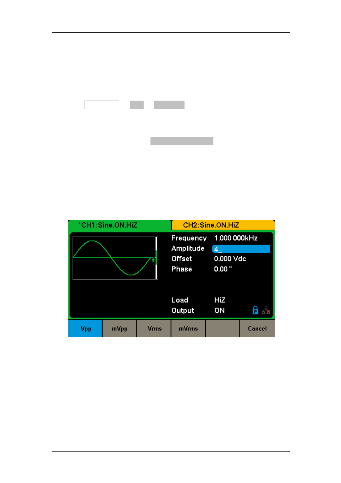
To Set the Amplitude
The amplitude setting range is limited by the ―Load‖ and ―Frequency/Period‖
settings. For detailed information, please refer to ―SDG2000X Datasheet‖.
1. Press Waveforms → Sine → Amplitude, to set the amplitude.
The amplitude shown on the screen when the instrument is powered on is the
default value or the set value of last power down. If setting the waveform‘s
high level is desired, press the Amplitude/HighLevel key again to switch into
the high level parameter (the current operation is displayed in inverse color).
2. Input the desired amplitude.
Use the numeric keyboard to input the parameter value directly, and press the
corresponding key to select the parameter unit. Or use the arrow keys to
select the digit to edit, and then use the knob to change its value.
Figure 2-3 Setting the Amplitude
To Set the Offset
The offset setting range is limited by the ―Load‖ and ―Amplitude/HighLevel‖
settings. For detailed information, please refer to ―SDG2000X Datasheet‖. The
default value is 0Vdc.
20 SDG2000X User Manual
Page 31

SIGLENT
1. Press Waveforms → Sine → Offset, to set the offset.
The offset shown on the screen when the instrument is powered on is the
default value or the set value of last power down. If you want to set the
waveform by low level, press the Offset/LowLevel key again, to switch into the
low level parameter (the current operation is displayed in inverse color).
2. Input the desired offset.
Use the numeric keyboard to input the parameter value directly, and press the
corresponding key to select the parameter unit. Or use the arrow keys to
select the digit to edit, and then use the knob to change its value.
Figure 2-4 Setting the Offset
To Set the Phase
1. Press Waveforms → Sine → Phase, to set the phase.
The Phase shown on the screen when the instrument is powered on is the
default value or the set value of last power down.
2. Input the desired phase.
Use the numeric keyboard to input the parameter value directly and press the
corresponding key to select the parameter unit. Or use the arrow keys to
SDG2000X User Manual 21
Page 32

select the digit to edit, and then use the knob to change its value.
Figure 2-5 Setting the Phase
SIGLENT
Note:
When the independent mode is enabled, the phase parameter cannot be
modified
22 SDG2000X User Manual
Page 33

SIGLENT
Function
Menu
Settings
Explanation
Frequency/
Period
Set the signal frequency or period;
The current parameter will be switched at a second press.
Amplitude/
HighLevel
Set the signal amplitude or high level;
The current parameter will be switched at a second press.
Offset/
LowLevel
Set the signal offset or low level;
The current parameter will be switched at a second press.
Phase
Set the phase of the signal.
DutyCycle
Set the duty cycle for square waveform.
2.2 To Set Square Waveform
Press Waveforms key to select the waveform function, and press the Square
softkey. The square waveform parameters are set by using the Square
operation menu.
The parameters of square waveforms include frequency/period,
amplitude/high level, offset/low level, phase and duty. As shown in Figure 2-6,
select DutyCycle. The duty cycle parameter area is highlighted in the
parameter display window, and users can set the duty cycle value here.
Figure 2-6 Square Parameters Display Interface
Table 2-2 Menu Explanations of Square Waveform
SDG2000X User Manual 23
Page 34

SIGLENT
To Set the Duty Cycle
Duty Cycle: The ratio of the amount of time the pulse is in the high state and
the waveform‘s period.
The duty cycle setting range is limited by the ―Frequency/Period‖ setting. For
detailed information, please refer to ―SDG2000X Datasheet‖. The default
value is 50%.
1. Press Waveforms → Square → DutyCycle, to set the duty cycle.
The duty cycle shown on the screen when the instrument is powered on is the
default value or the set value of last power down.
2. Input the desired Duty Cycle.
Use the numeric keyboard to input the parameter value directly and press the
corresponding key to select the parameter unit. Or use the arrow keys to
select the digit to edit, and then use the knob to change its value. The
generator will change the waveform immediately.
24 SDG2000X User Manual
Page 35

Note:
SIGLENT
Figure 2-7 Setting the Duty Cycle
The methods of setting other parameters of square signal are similar to sine
waveform function.
SDG2000X User Manual 25
Page 36

SIGLENT
Function
Menu
Settings
Explanation
Frequency/
Period
Set the signal frequency or period;
The current parameter will be switched at a second press.
Amplitude/
HighLevel
Set the signal amplitude or high level;
The current parameter will be switched at a second press.
Offset/
LowLevel
Set the signal offset or low level;
The current parameter will be switched at a second press.
Phase
Set the phase of the signal.
Symmetry
Set the symmetry for ramp waveform.
2.3 To Set Ramp Waveform
Press Waveforms key to select the waveform function, and press the Ramp
softkey. The ramp waveform parameters are set by using the ramp operation
menu.
The parameters for ramp waveforms include frequency/period, amplitude/high
level, offset/low level, phase and symmetry. As shown in Figure 2-8, in the soft
key menu, select Symmetry. The symmetry parameter area is highlighted in
the parameter display window, and users can set the symmetry value here.
Figure 2-8 Ramp Parameters Display Interface
Table 2-3 Menu Explanations of Ramp Waveform
26 SDG2000X User Manual
Page 37

SIGLENT
To Set the Symmetry
Symmetry: The percentage that the rising period takes up the whole Period.
Input Range: 0~100%
Default Value: 50%
1. Press Waveforms → Ramp → Symmetry, to set the symmetry.
The symmetry shown on the screen when the instrument is powered on is the
default value or the set value of last power down.
2. Input the desired Symmetry.
Use the numeric keyboard to input the parameter value directly, and press the
corresponding key to select the parameter unit. Or use the arrow keys to
select the digit to edit, and then use the knob to change its value. The
generator will change the waveform immediately.
Figure 2-9 Setting the Symmetry
Note:
The methods of setting other parameters of ramp signal are similar to sine
waveform function.
SDG2000X User Manual 27
Page 38

SIGLENT
Function
Menu
Settings
Explanation
Frequency/
Period
Set the signal frequency or period;
The current parameter will be switched at a second press.
Amplitude/
HighLevel
Set the signal amplitude or high level;
The current parameter will be switched at a second press.
Offset/
LowLevel
Set the signal offset or low level;
The current parameter will be switched at a second press.
PulWidth/
DutyCycle
Set the signal pulse width or duty cycle;
The current parameter will be switched at a second press.
Rise/
Fall
Setting the rise edge or fall edge for pulse waveform.
The current parameter will be switched at a second press.
Delay
Setting the delay for pulse waveform.
2.4 To Set Pulse Waveform
Press Waveforms key to select the waveform function, and press the Pulse
softkey. The pulse waveform parameters are set by using the pulse operation
menu.
The parameters for pulse waveforms include frequency/period, amplitude/high
level, offset/low level, width, rise/fall and delay. As shown in Figure 2-10, in the
soft key menu, select PulWidth. The pulse width parameter area is highlighted
in the parameter display window, and users can set the pulse width value
here.
Figure 2-10 Pulse Parameters Display Interface
Table 2-4 Menu Explanations of Pulse Waveform
28 SDG2000X User Manual
Page 39

SIGLENT
To Set the Pulse Width/DutyCycle
Pulse width is defined as the time from the 50% threshold of a rising edge
amplitude to the 50% threshold of the next falling edge amplitude (as shown in
the figure below). The pulse width setting range is limited by the ―Minimum
Pulse Width‖ and ―Pulse Period‖ setting. For detailed information, please refer
to ―SDG2000X Datasheet‖. The default value is 200μs.
Pulse duty cycle is defined as the percentage that the pulse width takes up in
the whole period. Pulse duty cycle and pulse width are correlative. Once a
parameter is changed, the other will be automatically changed.
1. Press Waveforms→ Pulse → PulWidth, to set the pulse width.
The pulse width shown on the screen when the instrument is powered on is
the default value or the set value of last power down. If you want to set the
waveform by duty, press the PulWidth/DutyCycle key again, to switch into the
duty parameter (the current operation is displayed in inverse color).
2. Input the desired Pulse Width.
Use the numeric keyboard to input the parameter value directly, and press the
corresponding key to select the parameter unit. Or use the arrow keys to
select the digit to edit, and then use the knob to change its value. The
SDG2000X User Manual 29
Page 40

generator will change the waveform immediately.
Figure 2-11 Setting the Pulse Width
SIGLENT
To Set the Rise/Fall Edge
Rise edge time is defined as the duration of the pulse amplitude rising from 10%
to 90% threshold, while fall edge time is defined as duration of the pulse
amplitude moving down from 90% to 10% threshold. The setting of rise/fall
edge time is limited by the currently specified pulse width limit. Users can set
rise edge and fall edge independently.
1. Press Waveforms → Pulse → Rise to set the rise edge.
The rise edge shown on the screen when the instrument is powered on is the
default value or the set value of last power down. If you want to set the
waveform by fall edge, press the Rise/Fall key again, to switch into the fall
edge parameter (the current operation is displayed in inverse color).
2. Input the desired rise edge.
Use the numeric keyboard to input the parameter value directly, and press the
corresponding key to select the parameter unit. Or use the arrow keys to
select the digit to edit, and then use the knob to change its value. The
generator will change the waveform immediately.
30 SDG2000X User Manual
Page 41

Note:
SIGLENT
Figure 2-12 Setting the Rise Edge
The methods of setting other parameters of pulse signal are similar to sine
waveform function.
SDG2000X User Manual 31
Page 42

SIGLENT
Function
Menu
Settings
Explanation
BandSet
Turn on/off the bandwidth setting.
Stdev
Setting the stdev for noise waveform.
Mean
Setting the mean for noise waveform.
Bandwidth
Setting the bandwidth for noise waveform.
2.5 To Set Noise Waveform
Press Waveforms key to select the waveform function, and press the Noise
softkey. The noise parameters are set by using the noise operation menu.
The parameters for noise include stdev, mean and bandwidth. As shown in
Figure 2-13, in the soft key menu, select Stdev, The stdev parameter area is
highlighted in the parameter display window, and users can set the stdev
value here. Noise is non-periodic signal which has no frequency or period.
Figure 2-13 Noise Parameters Display Interface
Table 2-5 Menu Explanations of Noise
To Set the Stdev
1. Press Waveforms → Noise → Stdev, to set the stdev.
32 SDG2000X User Manual
Page 43

SIGLENT
The stdev shown on the screen when the instrument is powered on is the
default value or the set value of last power down.
2. Input the desired stdev.
Use the numeric keyboard to input the parameter value directly, and press the
corresponding key to select the parameter unit. Or use the arrow keys to
select the digit to edit, and then use the knob to change its value.
Figure 2-14 Setting the Stdev
To Set the Mean
1. Press Waveforms → Noise → Mean, to set the mean.
The mean shown on the screen when the instrument is powered on is the
default value or the set value of last power down.
2. Input the desired mean.
Use the numeric keyboard to input the parameter value directly, and press the
corresponding key to select the parameter unit. Or use the arrow keys to
select the digit to edit, and then use the knob to change its value.
SDG2000X User Manual 33
Page 44

To Set the Bandwidth
SIGLENT
Figure 2-15 Setting the Mean
1. Press Waveforms → Noise → BandSet and choose ―On‖ to set the
bandwidth.
The bandwidth shown on the screen when the instrument is powered on is the
default value or the set value of last power on. When changing the function, if
the current value is valid for the new waveform, it will be used sequentially.
2. Input the desired bandwidth.
Use the numeric keyboard to input the parameter value directly, and press the
corresponding key to select the parameter unit. Or you can use the arrow keys
to select the digit you want to edit, and then use the knob to change its value.
34 SDG2000X User Manual
Page 45

Figure 2-16 Setting the Bandwidth
SIGLENT
SDG2000X User Manual 35
Page 46

SIGLENT
2.6 To Set DC Waveform
Press Waveforms → Page 1/2 → DC, to enter the following interface. Please
note that there is a ‗DC offset‘ parameter at the middle of the screen.
Figure 2-17 DC Setting Interface
Note:
The method of setting offset of DC signal is similar to sine waveform function.
36 SDG2000X User Manual
Page 47

SIGLENT
Function
menu
Settings
Explanations
Frequency/
Period
Set the signal frequency or period;
The current parameter will be switched at a second press.
Amplitude/
HighLevel
Set the signal amplitude or high level;
The current parameter will be switched at a second press.
Offset/
LowLevel
Set the signal offset or low level;
The current parameter will be switched at a second press.
Phase
Set the phase of the signal.
2.7 To Set Arbitrary Waveform
The Arb signal consists of two types: the system‘s built-in waveforms and the
user-defined waveforms. Built-in waveforms are stored in the internal
non-volatile memory. Users may also edit the arbitrary waveform with 8 to 8M
data points, namely 8pts to 8Mpts.
DDS
Choose Waveforms → Page 1/2 → Arb → Arb Mode and select the ―DDS‖
output mode. The parameters include frequency/period, amplitude/high level,
offset/low level and phase.
Figure 2-18 Arb Parameters Display Interface (DDS)
Table 2-6 Menu Explanations of Arb Waveform (Page 1/2)
In DDS output mode, users can set the frequency or period of the arbitrary
SDG2000X User Manual 37
Page 48

SIGLENT
Function
menu
Settings
Explanations
SRate/
Frequency
Set the signal sampling rate or frequency;
The current parameter will be switched at a second press.
Amplitude/
HighLevel
Set the signal amplitude or high level;
The current parameter will be switched at a second press.
Offset/
LowLevel
Set the signal offset or low level;
The current parameter will be switched at a second press.
Phase
Set the phase of the signal.
waveform. The instrument outputs an arbitrary waveform which is made up of
certain points according to the current frequency
TrueArb
Choose Waveforms → Page 1/2 → Arb → Arb Mode and select the ―TrueArb‖
output mode. The parameters include sampling rate/frequency, amplitude/high
level, offset/ low level and phase.
Figure 2-19 Arb Parameters Display Interface (TrueArb)
Table 2-7 Menu Explanations of Arb Waveform (Page 1/2)
In TrueArb output mode, users can set the sampling rate (the output points per
second) or frequency of the arbitrary waveform. The instrument outputs an
arbitrary waveform point by point according to the current sampling rate.
38 SDG2000X User Manual
Page 49

SIGLENT
To Set the Sampling Rate
1. Press Waveforms → Page 1/2 → Arb → TureArb → Srate, to set the
sampling rate parameter.
The sampling rate shown on the screen when the instrument is powered on is
the default value or the set value of last power on. When setting the function, if
the current value is valid for the new waveform, it will be used sequentially. If
you want to set the frequency for the waveform, press SRate/Frequency key
again, to switch to the frequency parameter (the current operation is displayed
in inverse color).
2. Input the desired sampling rate.
Use the numeric keyboard to input the parameter value directly, and press the
corresponding key to select the parameter unit. Or you can use the arrow keys
to select the digit you want to edit, and then use the knob to change its value.
Figure 2-20 Setting the Sampling Rate
Note:
The methods of setting the parameters of arbitrary signal are similar to sine
waveform function.
To select the built-in Arbitrary Waveform
SDG2000X User Manual 39
Page 50

SIGLENT
Item
Waveform
Explanation
Common
StairUp
Stair-up waveform
StairDn
Stair-down waveform
StairUD
Stair-up and down waveform
Trapezia
Trapezia waveform
Ppulse
Positive pulse
Npulse
Negative pulse
There are plenty of built-in Arbitrary Waveforms and user-defined Arbitrary
Waveforms inside the generator. To select one of them, follow the instructions
below.
1. To Select the Built-in Waveform
Choose Waveforms → Page 1/2 → Arb → Arb Type → Built-In to enter the
following interface, as shown in Figure 2-21.
Figure 2-21 Built-in Arbitrary Waveforms
Press Common, Math, Engine, Window, Trigo or other menus to switch to the
desired category (the selected category in the menu bar is highlighted), then
rotate the knob or click the touch screen to choose the desired waveform (the
selected waveform is highlighted). Select Accept or press the knob to recall
the corresponding waveform.
Table 2-8 Built-in Waveforms
40 SDG2000X User Manual
Page 51

SIGLENT
UpRamp
UpRamp waveform
DnRamp
DnRamp waveform
SineTra
Sine-Tra waveform
SineVer
Sine-Ver waveform
Math
ExpFall
ExpFall function
ExpRise
ExpRise function
LogFall
LogFall function
LogRise
LogRise function
Sqrt
Sqrt function
Root3
Root3 function
X^2
X2 function
X^3
X3 function
Airy
Airy function
Besselj
Bessel I function
Bessely
Bessel II function
Dirichlet
Dirichlet function
Erf
Error function
Erfc
Complementary error function
ErfcInv
Inverted complementary error function
ErfInv
Inverted error function
Laguerre
4-times Laguerre polynomial
Legend
5-times Legend polynomial
Versiera
Versiera
Sinc
Sinc function
Gaussian
Gaussian function
Dlorentz
Dlorentz function
Haversine
Haversine function
Lorentz
Lorentz function
Gauspuls
Gauspuls signal
Gmonopuls
Gmonopuls signal
Tripuls
Tripuls signal
Weibull
Weibull distribution
LogNormal
LogNormal Gaussian distribution
Laplace
Laplace distribution
Maxwell
Maxwell distribution
SDG2000X User Manual 41
Page 52

SIGLENT
Rayleigh
Rayleigh distribution
Cauchy
Cauchy distribution
Engine
Cardiac
Cardiac signal
Quake
Analog quake waveform
Chirp
Chirp signal
TwoTone
TwoTone signal
SNR
SNR signal
AmpALT
Gain oscillation curve
AttALT
Attenuation oscillation curve
RoundHalf
RoundHalf Waveform
RoundsPM
RoundsPM Waveform
BlaseiWave
Time-velocity curve of explosive oscillation
DampedOsc
Time-displacement curve of damped oscillation
SwingOsc
Kinetic energy – time curve of swing oscillation
Discharge
Discharge curve of NI-MH battery
Pahcur
Current waveform of DC brushless motor
Combin
Combination function
SCR
SCR firing profile
TV
TV signal
Voice
Voice signal
Surge
Surge signal
Radar
Analog radar signal
Ripple
Ripple wave of battery
Gamma
Gamma signal
StepResp
Step-response signal
BandLimited
Bandwidth-limited signal
CPulse
C-Pulse
CWPulse
CW pulse
GateVibr
Gate self-oscillation signal
LFMPulse
Linear FM pulse
MCNoise
Mechanical construction noise
Window
Hamming
Hamming window
Hanning
Hanning window
Kaiser
Kaiser window
Blackman
Blackman window
42 SDG2000X User Manual
Page 53

SIGLENT
GaussiWin
GaussiWin window
Triangle
Triangle window (Fejer window)
BlackmanH
BlackmanH window
Bartlett-Hann
Bartlett-Hann window
Bartlett
Bartlett window
BarthannWin
Modified Bartlett-Hann window
BohmanWin
BohmanWin window
ChebWin
ChebWin window
FlattopWin
Flat top weighted window
ParzenWin
ParzenWin window
TaylorWin
TaylorWin window
TukeyWin
TukeyWin (tapered cosine) window
Trigo
Tan
Tangent
Cot
Cotangent
Sec
Secant
Csc
Cosecant
Asin
Arc sine
Acos
Arc cosine
Atan
Arc tangent
ACot
Arc cotangent
CosH
Hyperbolic cosine
CosInt
Integral cosine
Coth
Hyperbolic cotangent
Csch
Hyperbolic cosecant
SecH
Hyperbolic secant
SinH
Hyperbolic sine
SinInt
Integral sine
TanH
Hyperbolic tangent
ACosH
Arc hyperbolic cosine
ASecH
Arc hyperbolic secant
ASinH
Arc hyperbolic sine
ATanH
Arc hyperbolic tangent
ACsch
Arc hyperbolic cosecant
ACoth
Arc hyperbolic cotangent
Square 1
SquareDuty01
Square waveform with 1% duty
SDG2000X User Manual 43
Page 54

SIGLENT
SquareDuty02
Square waveform with 2% duty
SquareDuty04
Square waveform with 4% duty
SquareDuty06
Square waveform with 6% duty
SquareDuty08
Square waveform with 8% duty
SquareDuty10
Square waveform with 10% duty
SquareDuty12
Square waveform with 12% duty
SquareDuty14
Square waveform with 14% duty
SquareDuty16
Square waveform with 16% duty
SquareDuty18
Square waveform with 18% duty
SquareDuty20
Square waveform with 20% duty
SquareDuty22
Square waveform with 22% duty
SquareDuty24
Square waveform with 24% duty
SquareDuty26
Square waveform with 26% duty
SquareDuty28
Square waveform with 28% duty
SquareDuty30
Square waveform with 30% duty
SquareDuty32
Square waveform with 32% duty
SquareDuty34
Square waveform with 34% duty
SquareDuty36
Square waveform with 36% duty
SquareDuty38
Square waveform with 38% duty
SquareDuty40
Square waveform with 40% duty
SquareDuty42
Square waveform with 42% duty
SquareDuty44
Square waveform with 44% duty
SquareDuty46
Square waveform with 46% duty
SquareDuty48
Square waveform with 48% duty
SquareDuty50
Square waveform with 50% duty
SquareDuty52
Square waveform with 52% duty
SquareDuty54
Square waveform with 54% duty
SquareDuty56
Square waveform with 56% duty
SquareDuty58
Square waveform with 58% duty
SquareDuty60
Square waveform with 60% duty
SquareDuty62
Square waveform with 62% duty
SquareDuty64
Square waveform with 64% duty
SquareDuty66
Square waveform with 66% duty
SquareDuty68
Square waveform with 68% duty
Square 2
SquareDuty70
Square waveform with 70% duty
44 SDG2000X User Manual
Page 55

SIGLENT
SquareDuty72
Square waveform with 72% duty
SquareDuty74
Square waveform with 74% duty
SquareDuty76
Square waveform with 76% duty
SquareDuty78
Square waveform with 78% duty
SquareDuty80
Square waveform with 80% duty
SquareDuty82
Square waveform with 82% duty
SquareDuty84
Square waveform with 84% duty
SquareDuty86
Square waveform with 86% duty
SquareDuty88
Square waveform with 88% duty
SquareDuty90
Square waveform with 90% duty
SquareDuty92
Square waveform with 92% duty
SquareDuty94
Square waveform with 94% duty
SquareDuty96
Square waveform with 96% duty
SquareDuty98
Square waveform with 98% duty
SquareDuty99
Square waveform with 99% duty
Medical
EOG
Electro-Oculogram
EEG
Electroencephalogram
EMG
Electromyogram
Pulseilogram
Pulseilogram
ResSpeed
Speed curve of the respiration
ECG1
Electrocardiogram 1
ECG2
Electrocardiogram 2
ECG3
Electrocardiogram 3
ECG4
Electrocardiogram 4
ECG5
Electrocardiogram 5
ECG6
Electrocardiogram 6
ECG7
Electrocardiogram 7
ECG8
Electrocardiogram 8
ECG9
Electrocardiogram 9
ECG10
Electrocardiogram 10
ECG11
Electrocardiogram 11
ECG12
Electrocardiogram 12
ECG13
Electrocardiogram 13
ECG14
Electrocardiogram 14
ECG15
Electrocardiogram 15
SDG2000X User Manual 45
Page 56

SIGLENT
LFPulse
Waveform of the low frequency pulse electrotherapy
Tens1
Waveform 1 of the nerve stimulation electrotherapy
Tens2
Waveform 2 of the nerve stimulation electrotherapy
Tens3
Waveform 3 of the nerve stimulation electrotherapy
Mod
AM
Sectional sine AM signal
FM
Sectional sine FM signal
PFM
Sectional pulse FM signal
PM
Sectional sine PM signal l
PWM
Sectional PWM signal
Filter
Butterworth
Butterworth filter
Chebyshev1
Chebyshev1 filter
Chebyshev2
Chebyshev2 filter
Demo
demo1_375pts
TureArb waveform 1(375 pts)
demo1_16kpts
TureArb waveform 1(16384 pts)
demo2_3kpts
TureArb waveform 2(3000 pts)
demo2_16kpts
TureArb waveform 2(16384 pts)
2. To Select the Stored Waveform
Choose Waveforms → Page 1/2 → Arb → Arb Type → Stored Waveforms to
enter the following interface, as shown in Figure 2-22.
Figure 2-22 Stored Waveform Display Interface
46 SDG2000X User Manual
Page 57

SIGLENT
Rotate the knob or touch the screen to choose the desired waveform. Then
select Recall or press the knob to recall the corresponding waveform.
SDG2000X User Manual 47
Page 58

SIGLENT
2.8 To Set Harmonic Function
The SDG2000X can be used as a harmonic generator to output harmonics
with specified order, amplitude and phase. According to the Fourier transform,
a periodic time domain waveform is the superposition of a series of sine
waveforms as shown in the equation below:
Generally, the component with f1 frequency is called fundamental waveform, f
is fundamental waveform frequency, A1 is fundamental waveform amplitude,
and φ1 is fundamental waveform phase. The frequencies of the other
components (called harmonics) are all integral multiples of the fundamental
waveform. Components whose frequencies are odd multiples of the
fundamental waveform frequency are called odd harmonics and components
whose frequencies are even multiples of the fundamental waveform frequency
are called even harmonics.
Press Waveforms → Sine → Harmonic and choose ―On‖, then press
Harmonic Parameter to enter the following interface.
1
Figure 2-23 Harmonic Interface
48 SDG2000X User Manual
Page 59

SIGLENT
Function
menu
Settings
Explanations
Type
Set the harmonic type to ―odd‖, ―ever‖ or ―all‖.
Order
Set the order of the harmonic.
Harmonic
Ampl
Set the amplitude of the harmonic.
Harmonic
Phase
Set the phase of the harmonic.
Cancel
Return to the sine parameters menu.
Table 2-9 Menu Explanations of Harmonic
To Select the Harmonic Type
The SDG2000X can output odd harmonics, ever harmonics and user-defined
orders of harmonics. After entering the harmonic setting menu, press Type to
select the desired harmonic type.
1. Press Even, the instrument will output fundamental waveform and even
harmonics.
2. Press Odd, the instrument will output fundamental waveform and odd
harmonics.
3. Press All, the instrument will output fundamental waveform and all the
user-defined orders of harmonics.
To Set the Harmonic Order
After entering the harmonic setting menu, press Order, the use the numeric
keyboard or knob to input the desired value.
The range is limited by the maximum output frequency of the instrument
and current fundamental waveform frequency.
Range: 2 to maximum output frequency of the instrument ÷ current
fundamental waveform frequency
The maximum is 10.
To Select the Harmonic Amplitude
After entering the harmonic setting menu, press Harmonic Ampl to set the
harmonic amplitude of each order.
1. Press Order to select the sequence number of the harmonic to be set.
SDG2000X User Manual 49
Page 60

SIGLENT
2. Press Harmonic Ampl to set the amplitude of the harmonic selected. Use
the arrow keys and knob to change the value. Or use the numeric
keyboard to input the amplitude value and then select the desired unit from
the pop-up menu. The units available are Vpp, mVpp and dBc.
To Select the Harmonic Phase
After entering the harmonic setting menu, press Harmonic Phase to set the
harmonic phase of each order.
1. Press Order to select the sequence number of the harmonic to be set.
2. Press Harmonic Phase to set the phase of the harmonic selected. Use the
arrow keys and knob to change the value. Or use the numeric keyboard to
input the phase value and then select the unit °.
50 SDG2000X User Manual
Page 61

SIGLENT
2.9 To Set Modulation Function
Use the Mod key to generate modulated waveforms. The SDG2000X can
generate AM, FM, ASK, FSK, PSK, PM, PWM and DSB-AM modulated
waveforms. Modulating parameters vary with the types of the modulation. In
AM, users can set the source (internal/external), depth, modulating frequency,
modulating waveform and carrier. In DSB-AM, users can set the source
(internal/external), modulating frequency, modulating waveform and carrier. In
FM, users can set the source (internal/external), modulating frequency,
frequency deviation, modulating waveform and carrier. In PM, users can set
the source (internal/external), phase deviation, modulating frequency,
modulating waveform and carrier. In ASK, users can set the source
(internal/external), key frequency and carrier. In FSK, users can set the source
(internal/external), key frequency, hop frequency and carrier. In PSK, users
can set the source (internal/external), key frequency, polarity and carrier. In
PWM, users can set the source (internal/external), modulating frequency,
width/duty cycle deviation, modulating waveform and carrier.
We will introduce how to set these parameters in details according to the
modulation types.
SDG2000X User Manual 51
Page 62

SIGLENT
Function
Menu
Settings
Explanation
Type
AM
Amplitude modulation
Source
Internal
The source is internal
External
The source is external. Use the [Aux In/Out] connector
at the rear panel.
AM Depth
Set the modulation depth.
Shape
Sine
Choose the modulating waveform.
Square
Triangle
UpRamp
DnRamp
Noise
2.9.1 AM
The modulated waveform consists of two parts: the carrier and the modulating
waveform. In AM, the amplitude of the carrier varies with the instantaneous
voltage of the modulating waveform.
Press Mod → Type → AM, the parameters of AM modulation are shown in
Figure 2-24.
Figure 2-24 Setting Interface of AM Modulation
Table 2-10 Menu Explanations of the AM Parameters
52 SDG2000X User Manual
Page 63

SIGLENT
Arb
AM Freq
Set the modulating waveform frequency. Frequency
range: 1mHz~1MHz (internal source only).
To Select Modulation Source
The SDG2000X can accept modulating signal from an internal or external
modulation source. Press Mod → AM → Source to select ―Internal‖ or
―External‖ modulation source. The default is ―Internal‖.
1. Internal Source
When internal AM modulation source is selected, press Shape to select Sine,
Square, Triangle, UpRamp, DnRamp, Noise or Arb as modulating waveform.
Square: 50% duty cycle
Triangle: 50% symmetry
UpRamp: 100% symmetry
DnRamp: 0% symmetry
Arb: the arbitrary waveform selected of the current channel
Note:
Noise can be used as modulating waveform but cannot be used as the carrier.
2. External Source
When external AM modulation source is selected, the generator accepts
external modulating signal from the [Aux In/Out] connector at the rear panel.
At this time, the amplitude of the modulated waveform is controlled by the
signal level applied to the connector. For example, if the modulation depth is
set to 100%, the output amplitude will be the maximum when the modulating
signal is +6V and the minimum when the modulating signal is -6V.
Key Points:
The SDG2000X can use one channel as a modulating source for the other
channel. The following example takes the output signal of CH2 as the
modulating waveform.
1. Connect the CH2 output terminal to [Aux In/Out] connector on the rear
SDG2000X User Manual 53
Page 64

SIGLENT
panel using a dual BNC cable.
2. Select CH1 and press Mod to select the desired modulation type as well as
set the corresponding parameters, and then select external modulation
source.
3. Select CH2 and select the desired modulating waveform and set the
corresponding parameters.
4. Press Output to enable the output of CH1.
To Set Modulation Depth
Modulation depth expressed as a percentage indicates the amplitude variation
degree. AM modulation depth varies from 1% to 120%. Press AM Depth to set
the parameter.
In the 0% modulation, the output amplitude is the half of the carrier‘s
amplitude.
In the 120% modulation, the output amplitude is the same with the
carrier‘s amplitude.
For an external source, the depth of AM is controlled by the voltage level
on the connector connected to the [Aux In/Out]. ±6V correspond to 100%
depth.
When external modulation source is selected, this menu is hidden.
To Set Modulation Frequency
When internal modulation source is selected, press AM Freq to highlight the
parameter, then use the numeric keyboard or arrow keys and knob to input the
desired value.
The modulation frequency ranges from 1mHz to 1MHz.
When external modulation source is selected, this menu is hidden.
54 SDG2000X User Manual
Page 65

SIGLENT
Function
Menu
Settings
Explanation
Type
DSB-AM
DSB Amplitude modulation.
Source
Internal
The source is internal.
External
The source is external. Use the [Aux In/Out] connector
at the rear panel.
DSB Freq
Set the modulating waveform frequency. Frequency
range: 1mHz~1MHz (internal source only).
Shape
Sine
Choose the modulating waveform.
Square
Triangle
UpRamp
DnRamp
Noise
Arb
2.9.2 DSB-AM
DSB-AM is an abbreviation for Double-Sideband Suppressed Carrier –
Amplitude Modulation. Press Mod → Type → DSB-AM. The parameters of
DSB-AM modulation are shown in Figure 2-25.
Figure 2-25 Setting Interface of DSB-AM Modulation
Table 2-11 Menu Explanations of the DSB-AM Parameters
SDG2000X User Manual 55
Page 66

SIGLENT
Note:
The methods of setting the parameters of DSB-AM are similar to AM.
56 SDG2000X User Manual
Page 67

SIGLENT
Function
Menu
Settings
Explanation
Type
FM
Frequency modulation
Source
Internal
The source is internal
External
The source is external. Use the [Aux In/Out] connector
at the rear panel.
Freq Dev
Set the frequency deviation
Shape
Sine
Choose the modulating waveform.
Square
Triangle
UpRamp
DnRamp
Noise
2.9.3 FM
The modulated waveform consists of two parts: the carrier and the modulating
waveform. In FM, the frequency of the carrier varies with the instantaneous
voltage of the modulating waveform.
Press Mod → Type → FM, the parameters of FM modulation are shown in
Figure 2-26
Figure 2-26 Setting Interface of FM Modulation
Table 2-12 Menu Explanations of the FM Parameters
SDG2000X User Manual 57
Page 68

SIGLENT
Arb
FM Freq
Set the modulating waveform frequency. Frequency
range 1mHz~1MHz (internal source).
To Set Frequency Deviation
Press FM Dev to highlight the parameter, and then use the numeric keyboard
or arrow keys and knob to input the desired value.
The deviation should be equal to or less than the carrier frequency.
The sum of the deviation and the carrier frequency should be equal to or
less than maximum frequency of the selected carrier waveform.
Note:
The methods of setting other parameters of FM are similar to AM.
58 SDG2000X User Manual
Page 69

SIGLENT
Function
Menu
Settings
Explanation
Type
PM
Phase modulation
Source
Internal
The source is internal
External
The source is external. Use the [Aux In/Out] connector
at the rear panel.
Phase Dev
Phase deviation ranges from 0° ~ 360°.
Shape
Sine
Choose the modulating waveform.
Square
Triangle
UpRamp
DnRamp
Noise
2.9.4 PM
The modulated waveform consists of two parts: the carrier and the modulating
waveform. In PM, the phase of the carrier varies with the instantaneous
voltage level of the modulating waveform.
Press Mod → Type → PM, the parameters of PM modulation are shown in
Figure 2-27.
Figure 2-27 Setting Interface of PM Modulation
Table 2-13 Menu Explanations of the PM Parameters
SDG2000X User Manual 59
Page 70

SIGLENT
Arb
PM Freq
Set the modulating waveform frequency. Frequency
range: 1mHz~1MHz.
To Set Phase Deviation
Press Phase Dev to highlight the parameter, and then use the numeric
keyboard or arrow keys and knob to input the desired value.
Use the numeric keyboard or arrow keys and knob to input the desired
value.
The range of phase deviation is from 0° to 360° and the default value is
100°.
Note:
The methods of setting other parameters of PM are similar to AM.
60 SDG2000X User Manual
Page 71

SIGLENT
Function
Menu
Settings
Explanation
Type
FSK
Frequency shift keying modulation.
Source
Internal
The source is internal.
External
The source is external. Use the [Aux In/Out] connector at
the rear panel.
Key Freq
Set the frequency at which the output frequency shifts
between the carrier frequency and the hop frequency
(internal modulation only): 1mHz~1MHz.
Hop Freq
Set the hop frequency.
2.9.5 FSK
The FSK is Frequency Shift Keying, the output frequency of which switches
between two preset frequencies (carrier frequency and the hop frequency or
sometimes known as mark frequency (1) and space frequency (0)).
Press Mod → Type → FSK, the parameters of FSK modulation are shown in
Figure 2-28.
Figure 2-28 Setting Interface of FSK Modulation
Table 2-14 Menu Explanations of the FSK Parameters
To Set Key Frequency
When internal modulation source is selected, press Key Freq to set the rate at
which the output frequency shifts between ―carrier frequency‖ and ―hop
SDG2000X User Manual 61
Page 72

SIGLENT
frequency‖.
Use the numeric keyboard or arrow keys and knob to input the desired
value.
The key frequency ranges from 1mHz to 1MHz.
When external modulation source is selected, this menu is hidden.
To Set Hop Frequency
The range of the hop frequency depends on the carrier frequency currently
selected. Press Hop Freq to highlight the parameter, and then use the numeric
keyboard or arrow keys and knob to input the desired value.
Sine: 1uHz~120MHz
Square: 1uHz~25MHz
Ramp: 1uHz~1MHz
Arb: 1uHz~20MHz
Note:
The methods of setting other parameters of FSK are similar to AM. In addition,
the external modulating signal of FSK must be Square which complies with the
CMOS level specification.
62 SDG2000X User Manual
Page 73

SIGLENT
Function
Menu
Settings
Explanation
Type
ASK
Amplitude shift keying modulation.
Source
Internal
The source is internal.
External
The source is external. Use the [Aux In/Out] connector at
the rear panel.
Key Freq
Set the frequency at which the output amplitude shifts
between the carrier amplitude and zero (internal
modulation only): 1mHz~1MHz.
2.9.6 ASK
When using ASK (Amplitude Shift Keying), the carrier frequency and key
frequency will need to be set. The key frequency is the shift rate of modulated
waveform amplitude.
Press Mod → Type → ASK, the parameters of ASK modulation are shown in
Figure 2-29.
Figure 2-29 Setting Interface of ASK Modulation
Table 2-15 Menu Explanations of the ASK Parameters
Note:
The methods for setting the parameters of ASK are similar to AM. In addition,
the external modulating signal of ASK must be Square which complies with the
CMOS level specification.
SDG2000X User Manual 63
Page 74

SIGLENT
Function
Menu
Settings
Explanation
Type
PSK
Phase shift keying modulation.
Source
Internal
The source is internal.
External
The source is external. Use the [Aux In/Out] connector at
the rear panel.
Key Freq
Set the frequency at which the output phase shifts
between the carrier phase and 180° (internal modulation
only): 1mHz~1MHz.
Polarity
Positive
Set the modulating polarity.
Negative
2.9.7 PSK
When using PSK (Phase Shift Keying), configure the generator to ―shift‖ its
output phase between two preset phase values (carrier phase and modulating
phase). The default modulating phase is 180°.
Press Mod → Type → PSK, the parameters of PSK modulation are shown in
Figure 2-30.
Figure 2-30 Setting Interface of PSK Modulation
Table 2-16 Menu Explanations of the PSK Parameters
Note:
64 SDG2000X User Manual
Page 75

SIGLENT
The methods of setting the parameters of PSK are similar to AM. In addition,
the external modulating signal of PSK must be Square which complies with
the CMOS level specification.
SDG2000X User Manual 65
Page 76

SIGLENT
Function
Menu
Settings
Explanation
Type
PWM
Pulse width modulation. The carrier is pulse.
Source
Internal
The source is internal.
External
The source is external. Use the [Aux In/Out] connector at
the rear panel.
Width Dev
Set the width deviation.
Duty Dev
Set the duty deviation.
Shape
Sine
Choose the modulating waveform.
Square
Triangle
UpRamp
DnRamp
Noise
2.9.8 PWM
In PWM (Pulse Width Modulation), the pulse width of the pulse varies with the
instantaneous voltage of the modulating waveform. The carrier can only be
pulse.
Press Waveforms → Pulse → Mod, the parameters of PWM modulation are
shown in Figure 2-31
Figure 2-31 Setting Interface of PWM Modulation
Table 2-17 Menu Explanations of the PWM Parameters
66 SDG2000X User Manual
Page 77

SIGLENT
Arb
PWM Freq
Set the modulating waveform frequency. Frequency
range: 1mHz~1MHz (internal source only).
To Set Pulse Width/Duty Deviation
Width Deviation represents the variation of the modulated waveform pulse
width relative to the original pulse width. Press Width Dev to highlight the
parameter, and use the numeric keyboard or arrow keys and knob to input the
desired value, as shown in the Figure 2-32.
Figure 2-32 Width Deviation Setting Interface
The width deviation cannot exceed the current pulse width.
The width deviation is limited by the minimum pulse width and current
edge time setting.
Duty Deviation represents the variation (%) of the modulated waveform duty
relative to the original duty. Press Duty Dev to highlight the parameter, and
then use the numeric keyboard or arrow keys and knob to input the desired
value, as shown in the Figure 2-33.
SDG2000X User Manual 67
Page 78

Figure 2-33 Duty Deviation Setting Interface
The duty deviation cannot exceed the current pulse duty cycle.
SIGLENT
The duty deviation is limited by the minimum duty cycle and current edge
time setting.
Duty deviation and width deviation are correlative. Once a parameter is
changed, the other will be automatically changed.
Note:
The methods of setting other parameters of PWM are similar to AM.
68 SDG2000X User Manual
Page 79

SIGLENT
Function
Menu
Settings
Explanation
Sweep time
Set the time span of the sweep in which the frequency
changes from the start frequency to stop frequency.
Start Freq
Mid Freq
Set the start frequency of the sweep;
Set the center frequency of the sweep.
Stop Freq
Freq Span
Set the stop frequency of the sweep;
Set the frequency span of the sweep.
Source
Internal
Choose internal source as a trigger.
External
Choose external source as a trigger. Use the [Aux
In/Out] connector at the rear panel.
Manual
Trigger a sweep by manual.
Trig Out
Off
Disable trigger out.
On
Enable trigger out.
2.10 To Set Sweep Function
In the sweep mode, the generator steps from the start frequency to the stop
frequency in the sweep time specified by the user. The waveforms that
support sweep include sine, square, ramp and arbitrary.
Press Sweep key to enter the following menu. Set the waveform parameters
by using the operation menu.
Figure 2-34 Setting Interface of Sweep (Page 1/2)
Table 2-18 Menu Explanations of Sweep (Page 1/2)
SDG2000X User Manual 69
Page 80

SIGLENT
Page
1/2
Enter the next page.
Function
Menu
Settings
Explanation
Type
Linear
Set the sweep with linear profile.
Log
Set the sweep with logarithmic profile.
Direction
Up
Sweep upward.
Down
Sweep downward.
Page
2/2
Return to the previous page.
Figure 2-35 Setting Interface of Sweep (Page 2/2)
Table 2-19 Menu Explanations of Sweep (Page 2/2)
Sweep Frequency
Use start freq and stop freq or center freq and freq span to set the range of the
frequency sweep. Press the key again to switch between the two sweep range
modes.
.
Start Frequency and Stop Frequency
Start Frequency and Stop Frequency are the lower and upper limits of the
frequency for sweep. Start Frequency ≤ Stop Frequency.
70 SDG2000X User Manual
Page 81

SIGLENT
Choose Direction → Up, the generator will sweep from Start frequency to
Stop frequency.
Choose Direction → Down, the generator will sweep from Stop frequency
to Start frequency.
Center Frequency and Frequency Span
Center Frequency = (|Start Frequency + Stop Frequency|)/2
Frequency Span = Stop Frequency – Start Frequency
Sweep Type
SDG2000X provides ―Linear‖ and ―Log‖ sweep profiles and the default is
―Linear‖.
Linear Sweep
In linear sweep, the output frequency of the instrument varies linearly in the
way of ―a number of Hertz per second‖. Choose Sweep → Page 1/2 → Type
→ Linear, there is a straight line displayed on the waveform on the screen,
indicating that the output frequency varies linearly.
Figure 2-36 Linear Sweep Interface
SDG2000X User Manual 71
Page 82

SIGLENT
Log Sweep
In log sweep, the output frequency of the instrument varies in a logarithmic
fashion, that is, the output frequency changes in the way of ―decade per
second‖. Choose Sweep → Page 1/2 → Type → Log, there is an exponential
function curve displayed on the waveform on the screen, indicating that the
output frequency changes in a logarithmic mode.
Figure 2-37 Log Sweep Interface
Sweep Trigger Source
The sweep trigger source can be internal, external or manual. The generator
will generate a sweep output when a trigger signal is received and then wait
for the next trigger source.
1. Internal Trigger
Choose Source → Internal, the generator outputs continuous sweep
waveform when internal trigger is selected. The default is ―Internal‖. Choose
Trig Out → On, the [Aux In/Out] connector at the rear panel will output the
trigger signal.
2. External Trigger
Choose Source → External, the generator accepts the trigger signal inputted
72 SDG2000X User Manual
Page 83

SIGLENT
from the [Aux In/Out] connector at the rear panel when external trigger is
selected. A sweep will be generated once the connector receives a CMOS
pulse with specified polarity. To set the CMOS pulse polarity, choose Edge to
select ―Up‖ or ―Down‖.
3. Manual Trigger
Choose Source → Manual, a sweep will be generated from the corresponding
channel when the Trigger softkey is pressed when manual trigger is selected.
Choose Trig Out → On, the [Aux In/Out] connector at the rear panel will output
the trigger signal.
SDG2000X User Manual 73
Page 84

SIGLENT
Burst Type
Trigger Source
Carrier
N-Cycle
Internal/External/
Manual
Sine, Square, Ramp, Pulse, Arbitrary.
Infinite
External/Manual
Sine, Square, Ramp, Pulse, Arbitrary.
Gated
Internal/External
Sine, Square, Ramp, Pulse, Noise, Arbitrary.
2.11 To Set Burst Function
The Burst function can generate versatile waveforms in n this mode. Burst
times can last a specific number of waveform cycles (N-Cycle mode), or when
an external gated signals (Gated mode) is applied. Any waveform (except DC)
may be used as the carrier, but noise can only be used in Gated mode.
Burst Type
SDG2000X provides three burst types including N-Cycle, Infinite and Gated.
The default is N-Cycle.
Table 2-20 Relations among burst type, trigger source and carrier
N-Cycle
In N-Cycle mode, the generator will output waveform with a specified number
of cycles after receiving the trigger signal. Waveforms that support N-Cycle
burst include sine, square, ramp, pulse and arbitrary.
Press Burst → NCycle → Cycles, and use the numeric keyboard or arrow
keys and knob to input the desired cycles. Set the waveform parameters by
using the operation menu, as shown in Figure 2-38 and Figure 2-39.
74 SDG2000X User Manual
Page 85

SIGLENT
Function
Menu
Settings
Explanation
NCycle
Use the N-Cycle mode.
Cycles
Infinite
Set the number of the bursts in N-Cycle.
Set the number of the bursts in N-Cycle to be infinite.
Start Phase
Set the start phase of the burst.
Burst Period
Set the burst period.
Source
Internal
Choose internal source as a trigger.
External
Choose external source as a trigger. Use the [Aux
In/Out] connector at the rear panel.
Manual
Trigger a burst by manual.
Page
1/2
Enter the next page.
Figure 2-38 N-Cycle Burst Interface (Page 1/2)
Table 2-21 Menu Explanations of the N-Cycle Burst (Page 1/2)
SDG2000X User Manual 75
Page 86

SIGLENT
Function
Menu
Settings
Explanation
Delay
Set the delay time before the burst starts.
Trig Out
Off
Disable trigger out.
On
Enable trigger out.
Page
2/2
Return to the previous page.
Figure 2-39 N-Cycle Burst Interface (Page 2/2)
Table 2-22 Menu Explanations of the N-Cycle Burst (Page2/2)
Infinite
In infinite mode, the cycle number of the waveform is set as an infinite value.
The generator outputs a continuous waveform after receiving the trigger signal.
Waveforms that support infinite mode include sine, square, ramp, pulse and
arbitrary.
Press Burst → NCycle → Infinite, and set the trigger source to ―external‖ or
―manual‖. The screen will display an infinite cycle burst, as shown in Figure
2-40 Infinite Burst InterfaceFigure 2-40.
76 SDG2000X User Manual
Page 87

SIGLENT
Figure 2-40 Infinite Burst Interface
Gated
In gated mode, the generator controls the waveform output according to the
gate signal level. When the gated signal is ―true‖, the generator outputs a
continuous waveform. When the gated signal is ―false‖, the generator first
completes the output of the current period and then stops. Waveforms that
support gated burst include sine, square, ramp, pulse, noise and arbitrary.
Press Burst → Gated, to enter the following interface.
Figure 2-41 Gated Burst Interface
SDG2000X User Manual 77
Page 88

Function
Menu
Settings
Explanation
Gated
Use the gated mode.
Polarity
Positive
Set the polarity for the gated signal.
Negative
Start Phase
Set the start phase of the burst.
Burst Period
Set the burst Period.
Source
Internal
Choose internal source as a trigger.
External
Choose external source as a trigger. Use the [Aux
In/Out] connector at the rear panel.
Start Phase
SIGLENT
Table 2-23 Menu Explanations of the Gated Burst
Define the start point in a waveform. The phase varies from 0° to 360°, and the
default setting is 0°. For an Arbitrary Waveform, 0° is the first waveform
point.
Burst Period
Burst Period is only available when the trigger source is internal. It is defined
as the time from the start of a burst to the start of the next one. Choose Burst
Period and use the numeric keyboard or arrow keys and knob to input the
desired value.
Burst Period ≥ 0.99μs + carrier period × burst number
If the current burst period set is too short, the generator will increase this
value automatically to allow outputting the specified number of cycles.
Cycles/Infinite
Set the number of waveform cycle in an N-Cycle (1 to 50,000 or Infinite).
If Infinite is chosen, then a continuous waveform will be generated once a
trigger occurs.
78 SDG2000X User Manual
Page 89

SIGLENT
Delay
Set the time delay between the trigger input and the start of the N-Cycle burst.
Burst Trigger Source
The burst trigger source can be internal, external or manual. The generator
will generate a burst output when a trigger signal is received and then wait for
the next trigger source.
1. Internal Trigger
Choose Source → Internal, the generator outputs continuous burst waveform
when internal trigger is selected. Choose Trig Out as ―Up‖ or ―Down‖, the [Aux
In/Out] connector at the rear panel will output a trigger signal with specified
edge.
2. External Trigger
Choose Source → External, the generator accepts the trigger signal inputted
from the [Aux In/Out] connector at the rear panel when external trigger is
selected. A burst will be generated once the connector gets a CMOS pulse
with specified polarity. To set the CMOS pulse polarity, choose Edge to select
―Up‖ or ―Down‖.
3. Manual Trigger
Choose Source → Manual, a burst will be generated from the corresponding
channel when the Trigger softkey is pressed when manual trigger is selected.
SDG2000X User Manual 79
Page 90

SIGLENT
Function
Menu
Settings
Explanation
File Type
State
The setting of the generator;
Data
Arbitrary waveform file
Browse
View the current directory.
Save
Save the waveform to the specified path.
Recall
Recall the waveform or setting information in the specific
position of the memory.
Delete
Delete the selected file.
Page
1/2
Enter the next page.
2.12 To Store and Recall
SDG2000X can store the current instrument state and user-defined arbitrary
waveform data in internal or external memory and recall them when needed.
Press Store/Recall to enter the following interface.
Figure 2-42 Store/Recall Interface (Page 1/2)
Table 2-24 Menu Explanations of Save and Recall
80 SDG2000X User Manual
Page 91

SIGLENT
Function
Menu
Settings
Explanation
Copy
Copy the selected file.
Paste
Paste the selected file.
Cancel
Exit the Store/Recall interface.
Page
2/2
Return to the previous page.
Figure 2-43 Store/Recall Interface (Page 2/2)
Table 2-25 Menu Explanations of Save and Recall
2.12.1 Storage System
The SDG2000X provides an internal non-volatile memory (C Disk) and a USB
Host interface for external memory.
1. Local (C:)
Users can store instrument states and arbitrary waveform files to C Disk.
2. USB Device (0:)
There is a USB Host interface located on the left side of the front panel which
permits users to store/recall waveforms or update the firmware version by
U-Disk. When the generator detects a USB storage device, the screen will
show the drive letter ―USB Device (0:)‖ and display a prompt message ―USB
SDG2000X User Manual 81
Page 92

SIGLENT
device connected.‖, as shown in Figure 2-44. After removing the U-Disk, the
screen will display a prompt message ―USB device removed.‖ And ―USB
Device (0:)‖ in the storage menu will disappear.
Figure 2-44 Storage System
Note:
The SDG2000X can only identify files of which filenames consist of English
letters, number and underscore. If other characters are used, the name may
be displayed in the store and recall interface abnormally.
Browse
Use the knob to shift between the directories or click the corresponding
location on the screen to choose Local (C:) or USB Device (0:). Choose
Browse, press the knob or click the selected folder to open the current
directory.
Use the knob to switch between folder and files under the current directory.
Choose Browse, press the knob or click the selected folder to open the
subdirectory. Choose <up>, then choose Brower or press the knob to
return to the upper level directory.
2.12.2 File Type
82 SDG2000X User Manual
Page 93

SIGLENT
Choose Store/Recall → File Type to select the desired file type. Available file
types are State File and Data File.
State File
Store the instrument state in internal or external memory in ―*.xml‖ format. The
state file stored includes waveform parameters and modulation, sweep, burst
parameters of two channels and utility parameters.
Data File
The SDG2000X can recall the data files in ―*.csv‖ or ―*.dat‖ format from the
external memory and transfer them into ―*.bin‖ format then store them in the
internal memory. When it is done, the generator will enter the arbitrary
waveform interface automatically.
In addition, users can edit arbitrary waveforms with PC software — EasyWave,
download them to the internal memory through remote interface and store
them (in ―*.bin‖ format) in the internal memory.
SDG2000X User Manual 83
Page 94

SIGLENT
2.12.3 File Operation
To Save the Instrument State
Users can store the current instrument state in internal and external memories.
The storage will save the selected function (including the basic waveform
parameters, modulation parameters and other utility settings used.)
To save the instrument state, the procedures are given as followed:
1. Choose the file type to store.
Press Store/Recall → File Type → State, and choose state as the storage
type.
2. Choose the location of the file.
Choose a desired location by rotating the knob or clicking the corresponding
location on the touch screen.
3. Name the file.
Press Save, to enter the following interface.
Figure 2-45 Filename Input Interface
84 SDG2000X User Manual
Page 95

SIGLENT
Function
Menu
Settings
Explanation
Up Cursor upward to select.
Down
Cursor downward to select.
Select
Select the current character.
Delete
Delete the current character.
Save
Store the file with the current name.
Cancel
Return to the store/Recall interface.
Table 2-26 Menu Explanation of File Storage
Select the character
Users can select the desired character from the virtual soft keyboard by using
the knob or Up and Down menus. Or touch the location of the character on the
screen directly. Then choose Select to display the character selected in the
filename area.
Delete the character
Use the left and right arrow keys to move the cursor in the file name. Then
choose Delete to delete the corresponding character.
4. Save the file.
After finishing inputting filename, press Save. The generator will save the file
under the currently selected directory with the specified filename.
To Recall State File or Data File
To recall the instrument state or arbitrary waveform data, the procedures are
as follows:
1. Choose the file type.
Press Store/Recall → File Type, and choose state or data as the storage type.
SDG2000X User Manual 85
Page 96

SIGLENT
2. Choose the file to be recalled.
Rotate the knob or click the touch screen to select the file you want to recall.
3. Recall the file.
Choose Recall, press the knob or click the location of the file on the screen,
the generator will recall the selected file and display corresponding prompt
message when the file is read successfully.
To Delete File
To delete the instrument state or arbitrary waveform data, the procedures are
as follows:
1. Choose the file.
Rotate the knob or click the touch screen to select the file you want to delete.
2. Delete the file.
Choose Delete, the generator will display prompt message ‗Delete the file?‘
Then press Accept, the generator will delete the currently selected file.
To Copy and Paste File
SDG2000X supports the internal and external storage to copy files from each
other. For example, copy an arbitrary wave file in the U-disk to the instrument,
the procedure is as follows:
1. Choose the file type.
Press Store/Recall → File Type, and choose ―Data‖ as the storage type.
2. Choose the file to be copied.
86 SDG2000X User Manual
Page 97

SIGLENT
Rotate the knob to select USB Device (0:) and press the knob to open its
directory. Then rotate the knob to select the file you want to copy and press
Page 1/2 → Copy.
3. Paste the file.
Rotate the knob to select Local (C:) and press the knob to open its directory.
Then press Paste.
SDG2000X User Manual 87
Page 98

SIGLENT
Function
Menu
Settings
Explanation
System
Set the system configuration.
Test/Cal
Test and calibrate the instrument.
Counter
Frequency counter setting.
Output Setup
Set the output parameters of CH1 and CH2.
CH Copy
Coupling
Set the track, channel coupling or channel copy
function.
Page
1/2
Enter the next page.
2.13 To Set Utility Function
With the Utility function, the user can set the parameters of the generator such
as Sync, Interface, System Setting, Self Test and Frequency Counter, etc.
Press Utility to enter the utility menu, as shown in Figure 2-46 and Figure
2-47.
Figure 2-46 Utility Setup Interface (Page 1/2)
Table 2-27 Menu Explanations of Utility (Page1/2)
88 SDG2000X User Manual
Page 99

Figure 2-47 Utility Setup Interface (Page 2/2)
Function
Menu
Settings
Explanation
Interface
Set the parameters of remote interfaces.
Sync
Set the sync output.
CLKSource
Internal
Choose the system clock source.
External
Help
View the help information.
OverVoltage
Protection
Turn on/off the overvoltage protection function.
Page
2/2
Return to the previous page.
Table 2-28 Menu Explanations of Utility (Page2/2)
SIGLENT
SDG2000X User Manual 89
Page 100

Function
Menu
Settings
Explanation
Number
format
Set the number format.
Language
English
Set the language.
Chinese
PowerOn
Default
All the settings return to default when power on;
Last
All the settings return to the setting of last power on.
Set to
Default
Set all the settings to default.
Beeper
On
Open the beeper.
Off
Close the beeper.
Page
1/2
Enter the next page.
2.13.1 System Settings
Press Utility → System, to enter the following interface.
SIGLENT
Figure 2-48 System Setup Interface (Page 1/2)
Table 2-29 Menu Explanations of System Setup (Page 1/2)
90 SDG2000X User Manual
 Loading...