

Page 1

NITRO RASCAL ARF ASSEMBLY MANUAL
INTRODUCTION:
Congratulations on the purchase of your SIG Nitro Rascal ARF kit!
This model continues the great line of ARF Rascal kits, with their
great looks and superb flight characteristics. The Nitro Rascal
makes an almost perfect aircraft for those modelers looking for a
maximum amount of 1/2A performance out of a great looking
airplane. The Nitro Rascal ARF can be easily flown in smaller
fields but is equally at home on normal club-size flying sites. The
Nitro Rascal ARF was specifically designed to take full advantage
of the great power and reliability of the Norvel .049, .061, or .074
glow engines.
Performance? You bet! The SIG Nitro Rascal ARF is a very
capable airplane. It has a wide speed envelope from very quick at
full throttle to a virtual "crawl" at low throttle. It is fully capable of a
wide range of 3-channel aerobatics including beautiful rudder rolls,
spins, inverted flight, snap rolls, touch and goes, etc. And the
included 2-ounce fuel tank will allow you to enjoy 15 - 20 minute
flights, depending upon fuel management. The kit also includes a
great tail wheel assembly that provides excellent ground handling.
Like it's electric powered cousin, the Nitro Rascal is beautifully built
from balsawood and ply and expertly covered in premium
Oracover
®
polyester film, using the signature "Rascal" two-color
trim scheme. This also means that the covering on the Nitro
Rascal ARF is easily repairable and easy to work with. Assembly
is straight forward if you follow these instructions carefully.
Deviating from these instructions has the potential to cause
problems later in the assembly process or during flight. The
successful assembly and flying of this model is your responsibility,
so take your time and enjoy the process.
NITR
O RASCAL ARF SPECIFICATIONS:
Wing Span: 49"
Wing Area: 324 sq. in.
Length: 32.5"
Flying Weight: 18 - 20 oz.
Wing Loading: 8.0 - 8.8 oz./sq.ft.
Engines: .061 - .074
Radio Requirements: 3 Channels - 1 Micro Receiver
& 3 Micro Servos Required
RADIO EQUIPMENT:
The Nitro Rascal ARF derives its performance from several
factors. Two of these are its light ready to fly weight and generous
wing area. This combination makes for a very favorable wing
loading, allowing the airplane to perform very well with the
recommended Norvel engines. Since the Nitro Rascal ARF is
factory built, you can only control the final ready to fly weight by
choosing the most appropriate airborne radio equipment. In short,
the performance of this model will be great with the right
equipment but will be less so by choosing overweight or
inappropriate radio equipment. This is a simple reality that has to
be addressed. Fortunately, after-market receivers and servos,
appropriate for this model, are not only readily available and are of
good quality, they're now very reasonably priced.
In flight-testing our Nitro Rascal models, we've used a wide v ariety
of airborne radio equipment. For servos we have used and can
highly recommend Hitec
™
#HS-55 servos and the MAXX MX-50
servos. Similar servos are also available and can be used in the
Nitro Rascal, provided they are of the same size, weight and po wer
output. For receivers, we have used and can highly recommend
the Hitec
™
Electron 6 or the 555 Micro Receivers, as well as the
FMA M5 Micro Receiver. Again, other receivers may be useable
but make sure they are small enough and light enough. For best
performance, always avoid excess weight. DO NOT use single
conversion receivers for this aircraft. Such receivers are more
prone to interference and should NOT be used.
To power the airborne radio system, we used either a 270 or 300
mAh Ni-Cad battery pack. Properly charged, this pack provides an
honest 45 - 60 minutes of safe flying. These results can v ary so be
sure to cycle your battery pack to determine the safe amount of
operating time for your particular system.
ENGINE SELECTION:
The Nitro Rascal ARF model was specifically designed around the
Norvel
®
AME .061 R/C engine. This engine provides a lot of power
1
R
Page 2
and is perfect for a model of this size. The motor mount can be
easily enlarged a little to accommodate the Norvel
®
.074 BigMig
R/C engine and this will be covered in this Assembly Manual.
NOTE: Using engines any larger in displacement than the Norvel
®
.074 is totally unnecessary and is not recommended.
COVERING MATERIAL:
Your Nitro Rascal ARF has been professionally covered using
Oracover
®
. This material is world famous f or its ease of application,
light weight, and consistency of color. If you live in a dry climate,
you may notice that some wrinkles might develop after removing
the covered parts from their plastic bags. This is perfectly normal
in low humidity climates. The model was covered in a part of the
world with relatively high humidity and therefore the balsawood
was carrying a fair amount of moisture. When exposed to drier air,
the wood typically loses this moisture, dimensionally "shrinking" in
the process. This is what may cause some wrinkles. However,
wrinkles are easy to correct by simply using a heat iron.
We suggest covering the shoe of the iron with thin cotton cloth,
such as an old T-shirt, to prevent scratching. The iron should be
set to about 280
O
- 300OF. Use the heated iron over the wrinkle to
lightly shrink the material - do not press on it. Then lightly iron the
covering back down to the wood. You can also use a hobby-type
heat gun to re-shrink the covering but you must be ver y careful
around seams or joints. Re-heating seams may cause them to
"creep", making them unsightly. You must also be careful when
using a heat iron or heat gun when working around the side
windows and windshield - excess heat will distort these plastic
parts.
An easy way to avoid over-heating seams, joints, and the windows
when re-shrinking the covering is to protect them with wet paper
towels. Soak the paper towels in cold tap water and roll them in
strips for joints and seams. For windows and windshields, just
shape the wet towel as needed. The coolness of the wet towels
protects whatever is beneath them from heat.
For reference, your Nitro Rascal ARF was covered in Oracover
®
film with the following part numbers:
#10 White and
#21-29 Transparent Red or
#21-59 Transparent Blue
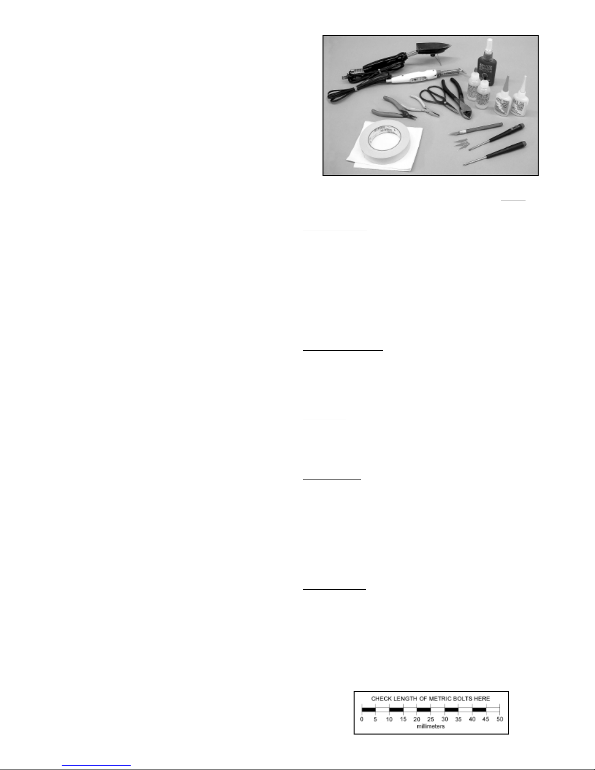
REQUIRED TOOLS:
For proper assembly, we suggest you have the following tools and
materials available:
• A Selection of Glues - SIG Thin and Thick CA
and SIG Kwik-Set 5-Minute Epoxy
• Threadlock Compound, Such as Loctite
®
Non-Permanent Blue
• Screwdriver Assortment
• Pliers - Needle Nose and Flat Nose
• Diagonal Wire Cutters
• Small Power Drill With Selection of Bits
• Pin Vise for Small Dia.Drill Bits
• Hobby Knife With Sharp #11 Blades
• Scissors
• Heat Iron and Trim Seal Tool
• Masking T ape
• Paper Towels
KIT CONTENTS: Perform a complete inventory bef
ore starting
assembly.
Pre-Built P
arts:
❑ 1 each Fuselage, Covered
❑ 1 each Fuselage Battery and Fuel Tank Access Hatch, Covered
❑ 1 each Fuselage Landing Gear Spreader, Covered
❑ 1 set Horizontal Stabilizer & Elevator Set, Covered
(With 4 CA Hinges in Place, Unglued)
❑ 1set Vertical Fin & Rudder Set, Covered
(With 3 CA Hinges in Place, Unglued)
❑ 1 set Left & Right Wing Panels, Covered
❑ 1 each Wing Center Section, Covered
❑ 1 set Plastic Wheel Pants, 1 Left, 1 Right
Formed Wire P
arts:
❑ 1 each Main Landing Gear Wire - .09 dia.
❑ 1 each Tail Wheel Assembly With Mounting Hardware
❑ 1 each Elevator Pushrod Wire - .040 x 24"
❑ 1 each Rudder Pushrod Wire - .040 x 24"
❑ 1 each Throttle Pushrod Wire - .040 x 14"
Hard
ware:
❑ 6 each
#2 x 3/8" Battery Hatch (2) and Engine Mounting Sheet
Metal Screws (4)
❑ 4 each
#2 x 1/4" Wheel Pant Mounting Sheet Metal Screws
❑ 2 each
Wheel Pant Mounting Brackets
Molded Parts:
❑ 1 each
#4-40 x 1" Nylon Wing Mounting Bolt
❑ 1 each
SIG 1-1/2" dia. Spinner Assembly With Metal Shaft
Adaptors (2) For Norvel
®
.061 and .074 Engines
❑ 1 each
60cc (2.02 oz.) Fuel Tank Assembly With All Required
Hardware
❑ 1 set
Clear Plastic Side Windows - 1 Left, 1 Right
❑ 1 set
Mini Nylon Rudder & Elevator Control Horns
❑ 3 each
Nylon Pushrod Retainers
❑ 2 each
Nylon Wheel Axle Caps
Miscellaneous:
❑ 1 each
3/16" x 3/8" x 2" Balsawood Fuel Tank Retainer
❑ 4 each
White Self-Adhesive Strips -1/4" x 10" - Wing Joint
Covering
❑ 2 each
Main Wheels - 1-3/4" dia.
❑ 1 each
Instrument Panel, Printed
❑ 1 each
Wheel Fairing Cardstock - 2-1/2" x 4-1/4"
❑ 1 each
Nitro Rascal Decal Set
❑ 1 each
Nitro Rascal Assembly Manual
2
Page 3
ASSEMBLY:
WINGS:
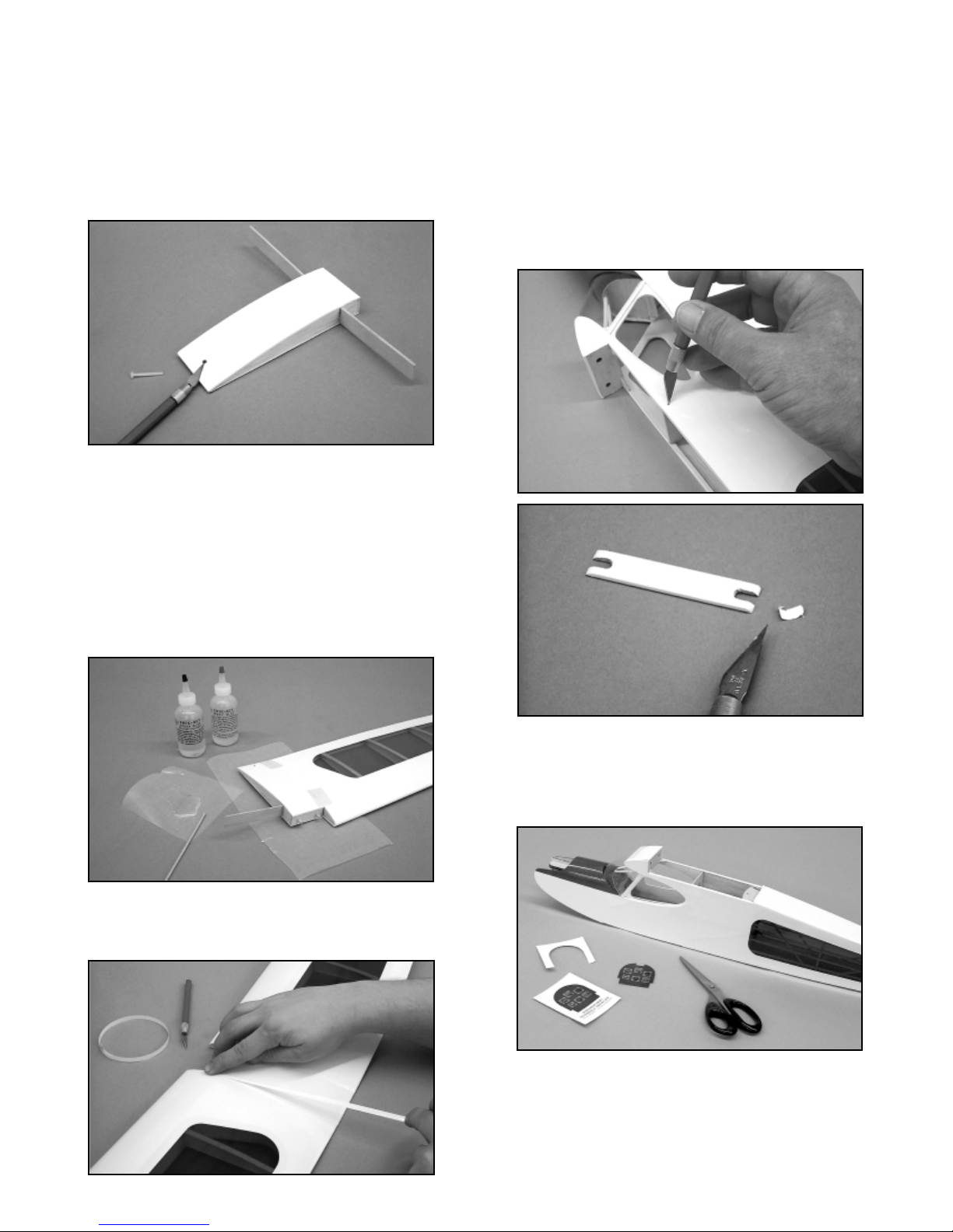
❑ 1) Start by using a hobby knife with a #11 blade to clear out the
rear wing bolt holes on the top and bottom of the wing center
section. Test fit the wing center section to the fuselage and secure
with the provided nylon 4-40 wing bolt. The fit will be good, with
the center section well centered on the fuselage.
❑ 2) Remove the center section from the fuselage and test fit the
wing panels onto the exposed plywood dihedral brace ends. The
fit should be firm. Use 5-minute epoxy to join one of the wing
panels to the wing center section. Apply glue to the correct side of
the exposed rib on the center section and also apply a thin coat
onto the plywood brace. Slide the center section plywood brace
into the slot in the appropriate wing panel. Press the wing panel
firmly in place to the center section. Wipe off all excess glue with
acetone or alcohol and tape the panel securely to the center
section - top and bottom. Allow the epoxy to set and glue the
remaining wing panel in place.
❑ 3) After the glue has set, use the four provided 1/4" x 10" selfadhesive strips of white Oracover
®
film to cover the bottom and top
wing joints, centering the covering over each joint. Save the
excess strip material. Check the fit of the completed wing to the
fuselage. Remove the wing and set it aside for now.
FUSELAGE:
❑ 1) Using a hobby knife and a sharp #11 blade, clear-out and
open up the various required holes in the fuselage covering; the
rear rudder and elevator control cable exits, the antenna exit hole
on the right fuselage side at the top just behind the window
location and the on/off switch slot on the left fuselage side,
beneath the side window. Also cut the covering away from the
slots on each side of covered plywood landing gear spreader.
❑ 2) From the kit contents, locate the printed instrument panel.
Use scissors to cut out the instrument panel including a recess at
the top, allowing clearance for the forward cockpit supports. Test
fit the instrument panel in place. Trim as needed for a good fit.
Glue panel to front fuselage cabin former using a little white glue.
❑ 3) The rudder and elevator servos are now installed into
fuselage. Note that the pre-installed r udder and elevator pushrod
tubes cross each other as the progress to the rear of the fuselage.
Therefore, viewing the fuselage from the rear, the rudder servo is
installed on the right side of the servo tray and the elevator ser vo
is installed next to it, on the left side. Both servo output arms face
3
Page 4

toward the fuselage sides at 90Oto the servo body. The throttle
servo is installed with its output arm aligned with the throttle
pushrod tube.
❑ 4) From the kit contents, locate the two .040 x 24" wire
pushrods for the rudder and elevator and one .040" x 14" pushrod
for the throttle. Using a pair of needle nose pliers, bend a simple
“Z”-bend into one end of each of the three pushrods. Insert the
straight, unbent end of one of the 24” pushrods into one of the
plastic pushrod tubes - just behind the servo tray - and feed it
through to the exit at the rear of the fuselage. This is easiest to do
by running the wire through one of the side window openings.
Install the remaining 24” pushrod in the same manner.
Feed the 14" throttle pushrod wire through the top rear wing
opening and into its plastic tube. Take care not to permanently
bend or kink the pushrod during this process. Remove the servo
output retaining screws in all three servos. Remove the output
arms and attach the "Z" bend end of each pushrod to its
corresponding output arm. Temporarily press each output arm
back in place onto the servos. Plug your servos into the
appropriate receptacles in the receiver and plug the battery pack
into the system. Turn the transmitter on, making sure the trim
levers are in neutral. Now reposition the rudder and elevator
output arms back onto their respective servos, as close to 90
O
as
possible to the servo body. The throttle output arm must move
back and forth to operate the engine's throttle lever, so set it at
about 20
O
to obtain roughly equal fore and aft movement. With the
output arms correctly in place, re-install the output arm retaining
screws and turn the radio system off.
❑ 5) The main landing gear is now glued in place in the fuselage
using 5-minute epoxy. First check the fit by sliding the landing gear
in place into the two slots at the bottom, front of the fuselage.
Carefully slide the gear all the way up into place inside the
fuselage to get a feel for the fit. Remove the gear from the
fuselage and use sandpaper to sand the wire, where it contacts the
fuselage sides. Apply 5-minute epoxy into each landing gear slot
on the inside of the fuselage - just enough to fill the slots. Once
again slide the landing gear wire in place into the fuselage.
Carefully wipe off any excess glue with alcohol and allow the glue
to set.
❑ 6) Fit the covered plywood landing gear spreader in place over
the wire landing gear legs and onto the bottom of the fuselage.
Trim as needed for a good fit. Remove the spreader and apply
5-minute epoxy to its bottom outside edges, where it contacts the
fuselage bottom. Also apply a little glue along the front edge of the
spreader where it butts against the bottom forward fuselage
sheeting. Press the spreader in place, wipe off any excess glue
with alcohol. Tape firmly and allow the glue to set.
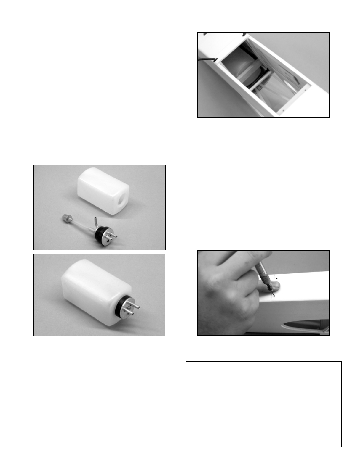
❑ 7) The 2-ounce (60cc) fuel tank supplied with this kit is now
assembled. We suggest using a simple two-line system in this
airplane. One fuel line is connected to the "clunk" or fuel pick-up
line and the engine's carburetor. The second line is the overflow
line for use when filling the tank. This same line is then connected
to the muffler pressure nipple, providing muffler pressure to the
fuel tank. Note that the "sides" of the fuel tank are the flat sides.
The rubber stopper for the tank has two holes all the way through
it. Use these two holes for the two aluminum fuel lines. Slip two
aluminum tubes through the rubber stopper. Slide the smaller
4
Page 5
diameter rear clamp plate over the two tubes and up against the
rear face of the rubber stopper. Slide the larger diameter front
plate over the two aluminum tubes at the front of the stopper and
up against the stopper itself. Press the clamp bolt through the front
plate and the rubber stopper, back to the rear plate. Use a
screwdriver to start the bolt threads into the rear plate - do not
tighten yet. At the front, leave approximately 1/4" of each tube
exposed in front of the plate. Gently bend the aluminum
overflowtube upwards to about 80
O
to reach the top of the tank
body - always leave about 1/32" space between the overflow tube
and the inside of the tank body. Trim the two tubes to appropriate
length and remove any burrs with sandpaper. Install the fuel pickup weight onto one end of the silicon tubing. Measure and cut the
tubing length to allow the fuel pick-up weight to just about reach
the rear of the fuel tank, allowing its free movement within the tankbody when the rubber stopper is fully in place in the front of the
tank. With everything now adjusted and fitting nicely, insert the
tank stopper assembly fully into the front of the tank body and use
a screwdriver to firmly tighten the clamp bolt while holding
the stopper assembly firmly in proper orientation. The bolt
compresses the rubber stopper between the plates, forming a
good tank seal.
❑ 8) The assembled fuel tank is now installed into the fuselage.
First, trial-fit the tank in place to check for the fit. Insert the tank
into the nose of the fuselage through the bottom Tank Hatch
opening and guide the front of the tank to the pre-cut round
opening in the firewall. The tank stopper should fit through this
hole and the tank body should fit up against the rear face of
the firewall. Remove the fuel tank from the fuselage. Apply a
generous bead of clear silicon adhesive (bathroom type is fine)
around the tank stopper at the front of the tank. Re-install the tank
into the fuselage - mak
e sure it is right side up - and press it
firmly in place against the firewall. From the kit contents, locate the
3/16" x 3/8" x 2" balsawood Fuel Tank Retainer. This retainer is
inserted into the fuselage, between the fuselage sides, at the rear
of the fuel tank to hold it firmly in place to the firewall. If needed,
lightly sand its ends to achieve a firm fit. Hold the retainer in place
and use a drop of two of thin CA glue to hold it in place to each
fuselage side.
❑ 9) Locate the pre-covered Tank/Battery Hatch from the kit
contents. This hatch has a plywood "lip" at one end and two
pre-drilled holes at the other end. The end with the lip is the front.
The hatch fits into the bottom of the fuselage and is removable for
ready access to the fuel tank and the battery compartment
beneath the tank. Install the front hatch lip into the fuselage,
beneath the landing gear spreader, pressing it firmly in place to the
fuselage.
Hold the hatch in place and use your pin vise and a .046" dia. drill
bit (#56 numbered drill) to drill two holes through the hatch
retention block, directly beneath the two pre-drilled holes. The
hatch can now be secured to the fuselage using the two #2 x 3/8"
sheet metal screws provided - do not over-tighten these screws,
just snug them in place to create the threads. Remove the screws
and the hatch from the fuselage. Apply a drop of thin CA glue into
each screw hole. Allow the glue to set and re-thread the screws
into each hole to establish the threads. Set the hatch and
mounting screws aside for now.
ENGINE INSTALLATION:
5
PROP T ALK:
Before installing the engine, it is important to give some thought to
suitable propellers for your airplane/engine combination. We have used
a variety of propellers for our Nitro Rascal ARF models and have
learned that different brands seem to all have different prop shaft
hole diameters. Usable prop sizes for the Norvel®.061 are 6" to 7" in
diameter. APC produces great props in these sizes but they are
produced with large diameter shaft holes. The Nor vel .061 engine has
a prop shaft size of .124. APC props in the 6" to 7" diameter have much
larger mounting holes. To mount an APC prop, we found that the
easiest way to center it to the Norvel prop shaft was to "sleeve" its
mounting hole with two short lengths of telescoping K&S aluminum
tubing. The inner piece of tubing has a 1/8" dia. I.D. which fits perfectly.
Page 6

❑ 1) Note that the down and right thrust angles have already been
built into the plywood motor mount. Also note that this instruction
assumes you are mounting the Norvel
®
.061 R/C engine. Begin by
removing the engine muffler from the engine, setting it aside for
now.
From the kit contents, locate the Spinner Assembly bag. You will
also need your prepared and ready to mount propeller. From the
spinner assembly bag, locate the aluminum adapter that has the
smaller hole in its center - this adapter is for the Norvel
®
.061
engine. Start by sliding the prop shaft washer onto the prop shaft
bolt, followed by the propeller, then the spinner backplate, and
finally, the aluminum spinner adapter ring that fits into the recess
in the back of the spinner backplate.
This assembly is now bolted onto the front of the engine. The
plastic spinner cone is fitted to the spinner backplate, aligning its
tabs into the backplate recesses. Mount the spinner cone to the
backplate using the two provided sheet metal screws.
❑ 2) Place the engine onto the fuselage engine mount plate. The
correct distance from the back face of the spinner to the very front
of the fuselage is 1/4". Use a scrap piece of 1/4" balsa as a
spacer on the left fuselage side and adjust the position of the
engine as shown. Use a soft lead pencil to carefully mark the four
engine mounting holes onto the plywood engine mounting plate.
Remove the engine.
Use a 1/16" dia. drill bit to drill four "pilot" holes squarely through
the marks in the motor mount.
Mount the engine to the plywood motor mount using the #2 x 3/8"
screws provided. Remove the screws and engine from the motor
mount. To protect these four holes from fuel damage, apply a
couple of drops of thin CA glue into each hole and allow the glue
to set. Now run each screw back into each hole to re-establish the
threads. Before final-mounting the engine, cut two 3" lengths of
small dia. silicon fuel tubing and slide one piece onto each of
the two aluminum fuel tank lines. Re-install the engine to the
motor mount. Trim and connect the two silicon fuel lines to the
carburetor and muffler pressure tap nipple.
6
(Continued...)
In the case of other propeller brands, some, such as Master Airscrew's
6" diameter props, require drilling out their smaller diameter mounting
holes with a 1/8" dia. drill bit. This is alw
ays best done with a drill press.
Finally , an y propeller used on a model airplane engine should alw
ays be
carefully balanced to run true and eliminate undue vibration.
In addition to adapting a propeller to the engine, you must also find a
small metal washer that has a 1/8" I.D. to fit the Norvel .061 prop shaft.
This is because the Norvel
®
prop shaft bolt is not long enough to engage
the engines threads with the spinner and prop in place, using the
standard Norvel®spinner/washer. We found that a Du-Bro Flat #4
washer worked perfectly.
We suggest that you prepare your propeller for mounting to the engine
bef
ore beginning the installation of the engine. For reference, a good
starting prop size for the Norvel®.061 R/C engine would be a 6 x 3.
Later, you can experiment with different pitch numbers and perhaps
even try a larger 7 x 3 prop.
Page 7

OPTIONAL - MOUNTING THE NORVEL .074 R/C ENGINE:
To mount this engine in your Nitro Rascal ARF, there are two
considerations to address first;
a) Widening the motor mount plate to accept the wider .074
crankcase body.
b) The need to create just a little more clearance for the larger
.074 muffler body.
The following instructions address these two requirements:
a) To accept the .074 crankcase body, each side of the motor
mount opening must be trimmed .040 (just under 3/64") - no more.
To do this, first use a small straight edge and sharp pencil to draw
a parallel line, 1/32" from the inside edge of each side of the motor
mount opening. Use a sanding block or a Dremel
®
Tool with a
sanding drum bit, to remove the excess material to the line just
drawn. Next use a sanding block to remove the plywood equally
from each side of the mount until the engine slips into place
easily. Use clear or colored dope to protect the exposed wood on
the trimmed motor mount plate.
b) The Norvel .074 muffler body is somewhat larger than the
.061 muffler. Without some trimming, it will come in contact with
the right fuselage side when in place. The balsawood sheeting on
the right fuselage side, at the nose, must be cleared to allow no
contact when the engine/muffler is in place. Simply use a hobby
knife and a sharp #11 blade to carefully cut away enough of the
right side nose sheeting to let the muffler clear without contact.
The exposed wood can then be clear doped or re-covered with a
scrap of covering material to protect it from fuel.
The engine can be mounted using the instructions provided in
Steps #1 and 2 above.
The only remaining engine installation task is to connect the
throttle pushrod to the throttle servo - this will be done in the
RADIO INSTALLATION section.
MOUNTING THE T AIL GROUP:
❑ 1) From the kit contents, locate the bags containing the
horizontal stabilizer and elevators and the ver tical fin and rudder.
7
the Norvel®.061 muffler has an exhaust exit that can be
positioned 360
O
, we found a lightweight and neat way to make a
simple exhaust extension.
To make this exhaust extension system, you will need a 5"
length of large 1/8" I.D. silicon tubing and a short length (1" or
so) of 3/16" O.D. K&S aluminum tubing. Use a sanding block or
a power-sanding disk to chamfer one end of the aluminum
tubing to a 45
O
angle. Clean up any burrs with a hobby knife and
sandpaper. Insert the unchamfered end of the aluminum tubing
into one end of the silicon tubing, about halfway. Insert the other
end of the silicon tubing into the bottom of the fuselage, through
the pre-cut drain hole on the bottom. Guide the tubing up
through the space just behind the engine itself in the motor
mount plate. Continue pulling the tubing until the end with the
aluminum tubing encounters the drain hole. Now gently insert
the aluminum tubing end about halfway into the drain hole, with
the 45
O
chamfer facing directly back toward the rear of the
fuselage.
At the top, trim the length of the silicon tubing to allow its end to
be pressed in place over the muffler nipple.
This simple exhaust extension does several things. It provides
a bit more back-pressure to the engine and improves the idle
without sacrificing a noticeable amount of power. Of course,
the number one benefit is that most of the exhaust residue is
directed down and out of the fuselage. Give it a try!
BUILDER’S TIP:
Small engines, running at high rpm's, can create a lot of exhaust
and carb spray that ultimately winds up on your model. Because
Page 8

Also locate the two plywood control horns. Note that the elevators
and rudder are only temporarily attached to the stabilizer and fin
with unglued CA hinges in their pre-cut slots. Remove the
elevators from the stabilizer and the rudder from the fin. Remove
the CA hinges from the slots.
❑ 2) The elevators can now be hinged in place to the horizontal
stabilizer. Carefully note that the two pre-drilled holes for the
elevator control horn are on the right
elevator half. The supplied
hinges are the CA type. Use only
instant or "thin" CA glue to install
these hinges!
Begin by inserting the four CA hinges into the four slots in the
trailing edge of the stabilizer, aligning their center slots along the
trailing edge. Using four thin pieces of wood or cardboard
(business card thickness is about right), insert these into the slots
in the hinge. Now mount the elevators to the exposed hinge
halves, pushing the elevators up to the scrap wood or cardboard
hinge inserts. Remove one of the hinge insert scraps, flex the
elevators downward, exposing the center of the hinge. Apply 3 or
4 drops of thin CA glue to the hinge, at the centerline. Turn the
stabilizer over and repeat this process on the same hinge. Repeat
the same procedure for the remaining three elevator hinges. Any
excess glue can be easily removed with a little SIG CA Debonder
and a paper towel. Because it takes a little time for the CA to fully
"wick" its way all through the hinge and into the surrounding wood,
leave the stabilizer/elevator assembly alone for at least 10 minutes
before moving the ele v ators. Flex the elevators firmly up and down
to make them supple and easy to move.
❑ 3) With the elevators in place, the horizontal stabilizer is now
glued in place to the top rear of the fuselage. Use SIG 5-minute
epoxy for this operation.
Begin by mounting the wing to the fuselage. Place the model on a
flat surface, allowing you to view it directly from the front. Prop up
the rear of the fuselage with a scrap piece of wood approximately
3". Apply epoxy glue to the fuselage stabilizer saddle area and
carefully place the stabilizer onto the saddle, centered as closely
as possible. Use pins or small weights to hold the stabilizer firmly
to the fuselage. Carefully view the airplane from the front to see if
the stab is squarely in place in relationship to the wing/fuselage,
without tilting to one side or the other. Make any adjustments
needed to position and hold the stabilizer in this position. Allow the
glue to set completely.
❑ 4) The vertical fin, without
the rudder hinged in place, is now
glued in place to the top of the stabilizer, again using SIG 5-min ute
epoxy.
Begin by first test fitting the vertical fin in place into the slot in the
top of the stabilizer, without using any glue. Trim if needed to
achieve full contact with the stabilizer and top rear of the fuselage.
Once again mount the wing to the fuselage and prop up the rear
of the fuselage about 3" with the airplane on a flat surface. Apply
glue to the bottom of the fin and the sides of its locating tab.
Carefully press the fin in place onto the stabilizer and fuselage.
Wipe off any excess glue, using alcohol and a cloth. Again view
the airplane from the front, making sure the fin is in place at 90
O
to
the stab. Use tape as needed to hold the fin in this position and
allow the glue to set. After the glue sets, remove the tape and the
wing.
❑ 5) Before hinging the rudder to the vertical fin it must be
prepared by inserting and gluing the tailwheel wire - with its metal
mounting bracket loosely in place - to the bottom leading edge of
the rudder. Measure 1/2" up from the bottom leading edge of the
rudder and place a small mark with a soft lead pencil. Use a 1/16"
drill bit to drill a hole at the previous marked location through the
8
X
X
X = X
O
O
90
90
X
X
Page 9

center of leading edge of the rudder to a depth of 1/2". Use a
hobby knife and a sharp #11 blade to cut a "V" notch in the
leading edge of the rudder from the hole to the bottom of the
rudder. Trial fit the tailwheel wire into the leading edge of the
rudder to make sure that the wire is flush with the leading edge of
the rudder. When satisfied with the fit of the tailwheel wire remove
it. Mix a small amount of 5-minute epoxy and carefully fill the hole
and the "V" notch with glue. Push the tailwheel wire into position
in the rudder and wipe off any excess glue that squeezes out.
Allow the glue to cure.
The rudder is now ready for hinging to the vertical fin and fuselage
with the three CA hinges.
The hinge slots for upper two CA hinges that fit into the vertical fin
are ready to use. The bottom hinge slot in the rear of the fuselage
has also been pre-cut at the factory, but is covered. It is necessary
to open this slot up to allow placement of the bottom rudder hinge.
To do this, use a sharp #11 blade to find and open the slot.
Reinstall the rudder and hinges and adjust the hinge gap between
the fin and rudder to 1/32". Use a piece of tape to hold the rudder
hard over to one side. On the opposite side, the hinges should be
visible. Apply 4 small drops of thin CA glue to each of the three
hinges at their exposed centers. Untape the rudder and flex it
hard over to the opposite side and again tape it in place. Apply
another 4 drops of glue to the opposite sides of each hinge.
Untape the rudder and position it in neutral. Allow about 10
minutes for the glue to fully "wick" through the hinges. When the
CA glue is fully set, flex the rudder back and forth firmly several
times to loosen and free-up the movement.
❑ 6) The metal tail wheel bracket/support is now mounted to the
bottom rear of the fuselage, using the supplied #2 x 1/4" screws.
With the fuselage upside down, place the metal support bracket in
front of the tailwheel wire, centered onto the fuselage bottom.
Mark the position of the two mounting holes onto the fuselage with
a soft pencil. Swing the bracket out of the way and use a 1/32" dia.
drill bit to make two pilot holes at the marks just made.
Mount the bracket firmly in place using the two #2 x 1/4" screws.
❑ 7) From the kit contents, locate the two white plastic control
horns. These are now mounted to the rudder and elevators. Note
that the rudder and elevators hav e two pre-drilled holes for this purpose. Viewing the airplane from the rear, the rudder horn is mounted on the left side of the rudder. The elevator control horn is
mounted to the bottom right elevator half. To mount the horns,
apply a small amount of thick CA glue to each "spike" and a dab of
thick CA glue to the bottom base of the horn, between the spikes.
Firmly press the control horn in place, making sure the holes are
facing forward toward the front of the fuselage. Allow the glue to
set.
WHEEL PANTS:
❑ 1) Position the wheel pants in place onto the wire landing gear
axles. Note that the inner facing sides of the wheel pants - the side
facing the fuselage - can be identified by looking inside and
observing the plywood mounting pads. Correctly in place, these
pads should be located against the upright wire landing gear wire.
From your parts bag, locate the two metal landing gear clips and
9
Page 10

the four #2 x 1/4" mounting screws.
❑ 2) The wheel pants must first be correctly aligned to the
landing gear wire and the fuselage, before mounting. This is done
by slipping the wheel pants in place over the landing gear wires without
installing the wheels - and then propping the rear of the
fuselage up 3" off of a flat surface. This provides the correct side
view alignment for mounting the wheel pants.
❑ 3) Press one of the metal landing gear clips onto the upright
wire leg of the landing gear, immediately next to the wheel pant.
Slide the clip up or down on the wire until the bolt holes are
approximately 3/8" above the axle hole. Use a sharp pencil to
mark the clip's two bolt hole centers onto the wheel pant. After
making these marks, remove the wheel pants from their axles.
Use a pin vise and a .046" dia. drill bit (#56 numbered drill) to drill
guide holes through the wheel pants and the inside plywood
mounting pads, at the marks just made.
❑ 4) Slip a wheel pant onto its appropriate axle and then inser t
one of the wheels into the pant and onto the axle. Continue
pushing the axle through the wheel hub and through the outer
wheel pant hole. Mount the pant and wheel to the landing gear
using the #2 screws through the clip and into the pre-drilled holes
on the side of the pant. Do not over-tighten the screws, just snug
them in place. Repeat this process for the remaining pant and
wheel. Test the wheel pant/wheel relationship, making sure that
the wheels roll freely with little or no friction. Adjust as needed to
achieve free movement.
OPTIONAL LANDING GEAR FAIRINGS:
Included with your kit is a card sheet measuring 2-1/2" x 4-1/4".
This is the material used to make the optional landing gear fairings.
Use the patterns provided in this manual. First remove the wheel
pants. Cut-out two landing gear fairings from the card stock and
bend them sharply in two at their leading edges. Mix a small
amount of 5-minute epoxy and spread it on the inside surface of
the fairing. Place the fairing onto the wire landing gear leg and
clamp or tape the trailing edge together. Align the fairing
accurately with the fuselage and allow the glue to cure.
10
Page 11

Use light sandpaper (#400 or similar grit) to lightly sand the trailing
edges smooth and sharp. These fairings can now be finished with
Oracover®film or primed and painted. Remount the wheel pants.
RADIO INSTALLATION:
With the servos already mounted, all that remains is to install the
radio system On/Off switch, the battery pack, the receiver and to
connect the rudder, elevator and throttle pushrods. Your airbor ne
battery pack should be charged and ready to use for these steps
and you should also have some pieces of lightweight foam for
wrapping and packing the battery and receiver within the fuselage.
❑ 1) The radio system On/Off switch is mounted on the left
fuselage side, beneath the side window. You will see a plywood
rectangle glued to the inside of the left fuselage side - this is the
switch mounting plate. In order to mount your switch you will need
to open the covering over the inner rectangular cutout to accept the
switch lever. Use a hobby knife and a sharp #11 blade to do this
neatly. The On/Off switch can now be mounted to the fuselage
using the mounting hardware that came with your radio system.
In our Nitro Rascal ARF models, we chose to use a Hitec
™
aftermarket "Micro" Switch Harness - P/N #54403, in the interest
of its lighter weight and much smaller size.
❑ 2) Wrap the batter y pack in light foam. Plug its connector into
the switch connector and install the pack into the nose of the
fuselage, directly beneath the fuel tank. The pack can be easily
held firmly in place with another piece of foam.
❑ 3) Plug the servo connectors into the appropriate receiver
receptacles (for most Mode II pilots, the rudder servo is plugged
into the aileron receptacle) and plug the switch connector into the
receiver's battery receptacle. Turn your transmitter on and test the
system to make sure the servos are moving in the correct
directions. Turn the radio system off. At this point, we re-installed
the bottom fuselage hatch. We then installed our foam wrapped
receiver directly onto the floor of the fuselage, in the cockpit area.
We first cut and fit a piece of light foam to fit on the fuselage floor.
We then placed the receiver onto this foam sheet, followed by
another thin foam sheet over the receiver.
The receiver antenna is routed out of the fuselage, through the
pre-drilled hole on the upper right fuselage side, above the side
window. The end of the antenna can then be attached to the top
of the vertical fin with a rubber band and a pin or, as we did, it can
be routed along the fuselage side and held in place beneath the
horizontal stabilizer, again with a rubber band and pin.
❑ 4) The carburetor arrangement on the Norvel
®
.061 R/C engine
has the throttle lever moving to the rear for full throttle and forward
for low throttle. Turn your transmitter on and set the throttle stick in
the full "low throttle" position. Set the transmitter throttle trim in the
neutral position to allow equal amounts of trim in either direction.
Now turn on the airborne radio system. The ser vo output arm on
the throttle servo should be in the low throttle position - arm
forward at about 20
O
. When the transmitter throttle stick is moved
up toward the full throttle position, the servo output arm should
likewise move toward the rear of the fuselage and in the full
throttle position, it should be about 20Otoward the rear. If
necessary, reposition the servo output arm on the servo until it
moves in this approximate manner. The linkage from the servo to
the engine throttle lever is now made.
Move the throttle servo to the full "low" position using the transmitter.
Use a fine tip felt marker to mark the location of the engine's
throttle lever hole - the lower of the two - onto the throttle pushrod
wire. Slide a plastic pushrod retainer onto the throttle pushrod,
moving it all the way back to the pushrod tube. Use needle nose
pliers to make a 90
O
bend in the pushrod wire at the mark just
made. Trim the end of the bent wire to within about 1/8". Slide the
pushrod retainer forward and flex its ar m outward to engage the
end of the wire. Press the wire through the retainers arm.
Test the action of the throttle using the transmitter. It should be
free and without binding. If your transmitter has EPA (End Point
Adjustments), use this feature to optimize the travel of the servo,
matching it to the movement of the throttle lever.
❑ 5) The rudder and elevator pushrods are now connected to the
control horns at the rear of the fuselage. Again, turn on the
transmitter and place the rudder and elevator trim lev ers in neutr al.
Turn on the airborne radio system. As previously described, the
output arms should be in position to the servo body at 90
O
. If
necessary, remove the output arms and reposition them back onto
the servo in this position.
Use a small piece of tape to hold the rudder in the neutral position
to the vertical fin. Turn the fuselage upside down. Hold the metal
pushrod wire up against rudder control horn, at the middle hole.
Use a fine tip felt marker to mark the wire exactly where this hole
is. Slide a plastic pushrod retainer onto the pushrod wire, moving
it all the way forward to the fuselage. Use needle nose pliers to
now bend the rudder pushrod wire to a 90
O
angle at the mark just
made. T rim the bent wire end to within 1/8" and press the bent end
through the middle hole in the control horn. Slide the retainer
forward and flex its arm to fit over the bent end of the wire.
Remove the piece of tape holding the rudder in neutral.
Test the rudder movement with the transmitter. It should move
smoothly without any binding and right transmitter stick movement
should produce right rudder movement. Check this twice and then
check it again! If needed, use the rudder (aileron) trim lever to set
the rudder in true neutral to the vertical fin.
11
Page 12

The elevator pushrod is connected to the elevator control horn in
the same manner as the rudder. We suggest using the outermost
hole in the control horn for the attachment point. Again, use small
pieces of tape to hold the elevators in the neutral position to the
horizontal stabilizer.
Test the movement of the elevators using the transmitter to make
sure everything is moving in the correct direction. If needed, use
the elevator trim lever on the transmitter to set the elevators in true
neutral.
RECOMMENDED INITIAL CONTROL MOVEMENTS:
RUDDER: 3/8" RIGHT - 3/8" LEFT
ELEVATORS: 1/4" UP - 1/4" DOWN
(Note that these control movements can be changed later
to suit your particular flying style and preferences)
SIDE WINDOW APPLICATION:
From the contents of your kit, locate the small bag containing the
molded side windows. We suggest using 5-minute epoxy or
RC-56 glue to mount the windows into the inside of the fuselage.
DO NOT use thin CA glue for this step! Use scissors to cut out
each window, leaving about 1/8" of plastic around the edges for a
gluing surface. Apply a thin bead of glue to these edges and press
the window in place from the inside of the fuselage. Use small
pieces of tape to hold the windows in place until the glue sets. A
little alcohol will clean off any excess glue from the windows.
DECAL APPLICATION:
The decals supplied with your Nitro Rascal ARF kit are high
quality Mylar with an extremely aggressive adhesive. These are
not die-cut and must be cut from the sheet with hobby knife and
sharp #11 blade or with sharp scissors.
We suggest the follo wing method to accurately apply these decals .
Carefully cut out the decal with a hobby knife . Lift it carefully off its
sheet with tweezers. Use a product like SIG Pure Magic Model
Airplane Cleaner, Fantastic
®
, or Windex®to spray the area of the
model that will receive the decal. Then spray the adhesive side of
the decal as well. Lightly position the decal in place on the model.
The liquid cleaner allows the decal to slide easily into the desired
position - do not press down on the decal. Once in position, hold
the decal lightly in place with your finger and use a paper towel to
gently dab the excess liquid away. Use a small squeegee to now
set the decal in place, removing all excess liquid and any air
bubbles. The Sig 4" Epoxy Spreader - #SIGSH678 - is perfect for
this job. Mop up any excess cleaner with a dry cloth and allow the
decals to set overnight. They will be solidly adhered to the model
without any air bubbles.
BALANCE:
IMPORTANT: The model is always balanced fully assembled with
the prop and spinner in place, the complete radio system installed,
and the fuel tank empty.
The correct CG (Center of Gravity) for your Nitro Rascal ARF
model is located precisely at the main wing spar location. This
means that when you place your fingers, one on each side of the
bottom of the wing, at the main spar location, the airplane should
balance in a le
vel position. If the nose hangs low, this means the
model is "nose heavy". If the tail hangs low, this means the model
is "tail heavy". If either of these conditions exist, you must make
adjustments to correct the problem. Never attempt to fly your
model in an out of balance condition. Since the airborne batter y
pack is the single heaviest component in the airplane, it can be
used to adjust almost any tail heavy or nose heavy condition. This
is simply done by repositioning the battery pack as needed to
correct the problem. In the unlikely event that moving the battery
pack will not correct the problem, then stick-on type lead weights
may be needed. These are available from your local hobby shop.
PRE-FLIGHT:
Before flying your Nitro Rascal we strongly suggest that you take
the time to break-in your engine and adjust the idle to its lowest
12
Page 13

possible reliable rpm idle. The high quality of the piston-to-cylinder
fit on Norvel engines makes break-in a must before attempting to
fly the model. Break the engine in per the factory instructions and
DO NOT use the molded plastic spinner provided in this kit during
break in. We recommend that you use an electric star ter to star t
the engine the first few times and using the propeller spinner/front
thrust washer provided with the engine. This helps to avoid
burning the plastic spinner with the electric starter during the
break-in process.
We use and highly recommend either SIG "Champion" 15% or
25% fuel for the Norvel
®
.061 and .074 R/C engines. These fuels
have both contain generous oil content, absolutely essential for
high-revving smaller 1/2A engines.
ENGINE TIP: Both the Norvel
®
.061 and .074 R/C engines have
an offset head idle stop bolt in the left side of the carburetor body,
just behind the needle valve. This bolt is in place to limit the
travel of the throttle arm at low throttle. We have found that if this
bolt is completely removed, the throttle lev er can then mo v e further
forward in low throttle movement with the throttle servo. This
means that an even lower idle speed can be obtained. However,
you must experiment a little to obtain the lowest possible reliab
le
idle speed, without killing the engine. Our experience with this
simple modification has given us very reliable low speed idle
characteristics and - after adjusting the trims on our transmitter even the ability to use the "Throttle Cut" f eature that is available on
some transmitters.
FLYING:
If you are new to the hobby/sport of flying R/C model airplanes, DO
NOT attempt to fly this model by yourself! There are hundreds of
AMA (Academy of Model Aeronautics) chartered R/C clubs in the
U.S. The easiest way to find clubs in your area is by simply asking
your local hobby retailer . AMA chartered clubs often have qualified
instructors who can teach you how to fly and perhaps even test fly
your model for you. If you are already an R/C pilot, then you will
likely have no problems at all with the Nitro Rascal.
Choose a calm day with little or no wind for the initial flights. This
is important in getting the model properly trimmed. We also
suggest that for the first few familiarization flight you or a flying
buddy hand-launch the model. When hand-launching, the airplane
must be launched straight and level directly into the wind, with the
nose aimed at a point on the ground about 75’ in front of you.
NEVER launch the model with the nose pointed up or the wings
tipped to one side or the other. The launch should be firm enough
to achieve flight speed but not overly hard. Later, when you're
more familiar with the airplane and how it flies, you can perfor m
R.O.G.(Rise Off Ground) takeoffs from smooth surfaces.
Using full throttle at launch is recommended. Fly the model to a
comfortable altitude and throttle back the engine to a comfortable
cruising speed. Use the transmitter trims to adjust the model for
straight and level flight. Once the model is trimmed to your liking
you can begin to explore the Nitro Rascal's flight envelope.
Throttle all the way back and get familiar with the low speed flight
characteristics. This is great information to have when it comes
time to set-up your first landing. While still at low throttle, test the
airplane's stall characteristics. Using the initial control movements
in this manual, we think you will find the stall fairly uneventful and
easy to control.
Throttle up and gain some altitude. The Nitro Rascal is capable
of some really nice 3-channel aerobatics, such as rudder rolls,
inverted flight, snap rolls, spins, high-speed passes, etc. It can do
all of this in a very small amount of flying space. The more you fly
your Nitro Rascal the more you will begin to appreciate the
airplane's agility and throttle reaction.
Landing your Nitro Rascal is typically a pleasure. Throttle back to
achieve a shallow rate of descent, tur n into the wind and allow the
airplane to settle in smoothly to a 3-point landing. With a little
either experience, you'll be landing your Nitro Rascal right in front
of you every time!
13
IMPORTANT NOTE: The Nitro Rascal ARF is a small, highly
maneuverable R/C model aircraft that can easily be flown in
smaller flying sites. However, it should always be flown in
areas that are appropriate for such models. NEVER fly this
model in close proximity to people, houses, etc. It is always
best to fly this model at flying sites specifically designated for
R/C models. Do yourself a favor and join your local R/C club you'll almost always get assistance and good advice and you
might even make a new friend or two!
MAIN GEAR FAIRING PATTERN
FOLD LINE
FOLD LINE
Page 14

14
LIMIT OF LIABILITY
The craftsmanship, attention to detail, and actions of the builder/flyer of this model airplane kit will
ultimately determine the airworthiness, flight performance, and safety of the finished model. SIG MFG.CO .’s
obligation shall be to replace those parts of the kit proven to be defective or missing. The user shall
determine the suitability of the product for his or her intended use and shall assume all risk and liability in
connection therewith.
CUSTOMER SERVICE
SIG MANUFACTURING COMPANY, INC.is totally committed to your success in both assembling and flying
the NITRO RASCAL ARF kit. Should you encounter any problem building this kit or discover any missing
or damaged parts, please feel free to contact us by mail or telephone.
SIG MANUFACTURING COMPANY, INC.
P.O. Box 520
Montezuma, IA 50171-0520
SIG MODELER’S ORDERLINE: 1-800-247-5008
(to order parts)
SIG MODELER’S HOTLINE: 1-641-623-0215
(for technical support)
SIG WEB SITE: www .sigmfg.com
WARNING! THIS IS NOT A TOY!
Flying machines of any form, either model-size or full-size, are not toys! Because of the speeds that
airplanes must achieve in order to fly, they are capable of causing serious bodily harm and property
damage if they crash. IT IS YOUR RESPONSIBILITY AND YOURS ALONE to assemble this model
airplane correctly according to the plans and instructions, to ground test the finished model before each
flight to make sure it is completely airworthy, and to always fly your model in a safe location and in a safe
manner. The first test flights should only be made by an experienced R/C flyer, familiar with high
performance R/C aircraft.
The governing body for radio-control model airplanes in the United States is the ACADEMY OF MODEL
AERONAUTICS, commonly called the AMA. The AMA SAFETY CODE provides guidelines for the safe
operation of R/C model airplanes. While AMA membership is not necessar ily mandatory, it is required by
most R/C flying clubs in the U.S.and provides you with important liability insurance in case your R/C model
should ever cause serious property damage or personal injury to someone else. For more information,
contact:
ACADEMY OF MODEL AERONAUTICS
5161 East Memorial Drive
Muncie, IN 47302
Telephone: (765) 287-1256
AMA WEB SITE: modelaircraft.org
 Loading...