

Page 1

Replacingthebattery
Beforeyoustart,printtheseinstructions.
ThissystemmaynotsupportbatteriesthatarenotgenuineLenovo-madeorauthorized.Thesesystemswill
continuetoboot,butmaynotchargeunauthorizedbatteries.
Attention:Lenovohasnoresponsibilityfortheperformanceorsafetyofunauthorizedbatteries,and
providesnowarrantiesforfailuresordamagearisingoutoftheiruse.
Toreplacethebatterywithanewone,readthefollowingprerequisites,andselectyourmodelfromthe
listbelowfortheinstruction.
Prerequisitesfortheprocedure
DANGER
Iftherechargeablebatterypackisincorrectlyreplaced,thereisdangerofanexplosion.Thebattery
packcontainsasmallamountofharmfulsubstances.T oavoidpossibleinjury:
•ReplaceonlywithabatteryofthetyperecommendedbyLenovo.
•Keepthebatterypackawayfromre.
•Donotexposeittoexcessiveheat.
•Donotexposeittowaterorrain.
•Donotshort-circuitit.
•Donotdrop,crush,puncture,orsubjecttostrongforces.Batteryabuseormishandlingcan
causethebatterytooverheat,whichcancausegassesorameto“vent”fromthebattery
packorcoincell.
Toreplacethebattery,followtheproceduresbelow.
Replacingthebatteryinstalledinthebatteryspaceofyourcomputer
1.Turnoffthecomputer,orenterhibernationmode.Thendisconnecttheacpoweradapterandallcables
fromthecomputer.
2.Closethecomputerdisplay,andturnthecomputerover.
118UserGuide
Page 2
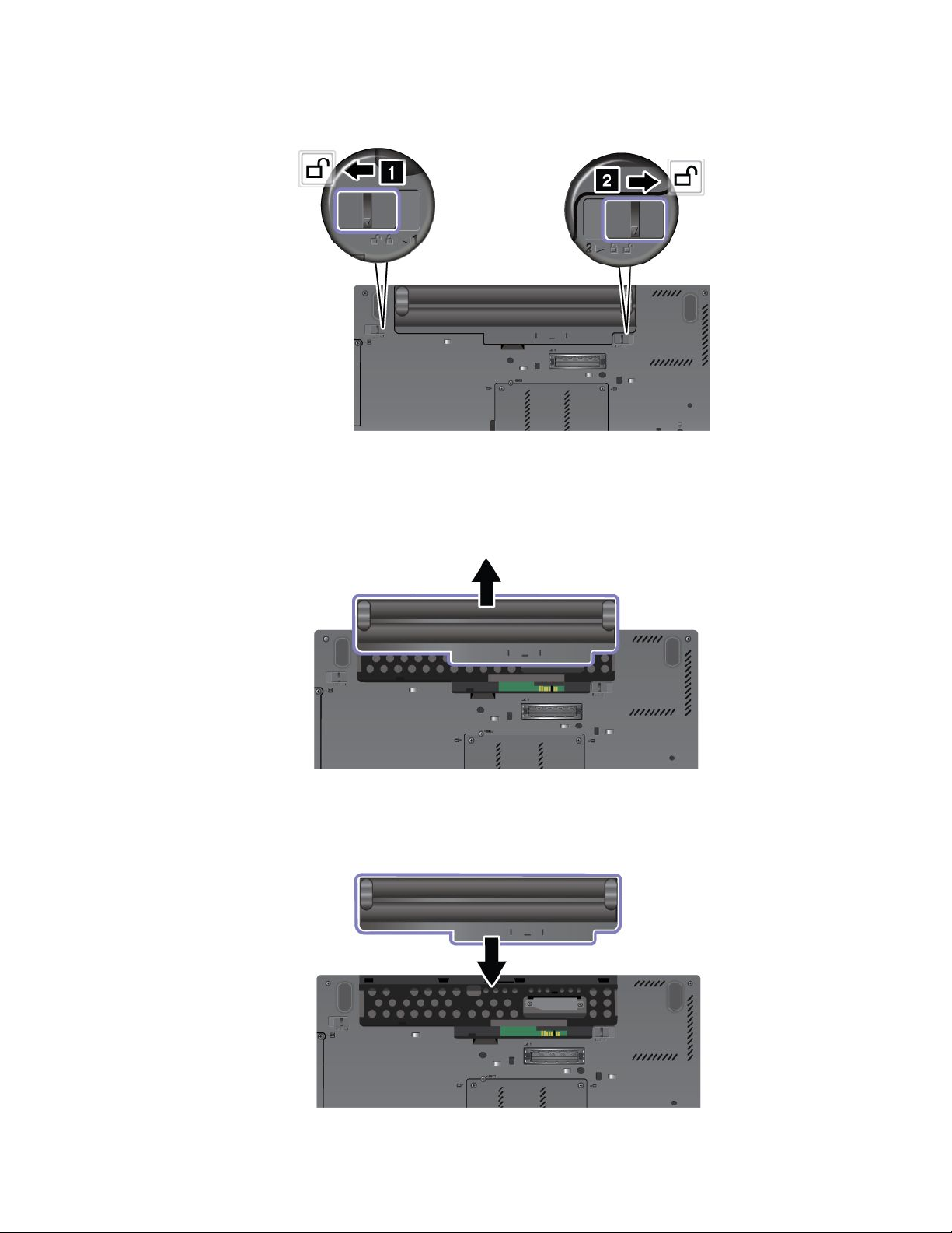
3.Unlockthebatterylatchbyslidingittotheunlockposition.
4.Removethebattery.
5.Slidethebatteryintothecomputer.
Chapter6.Replacingdevices119
Page 3
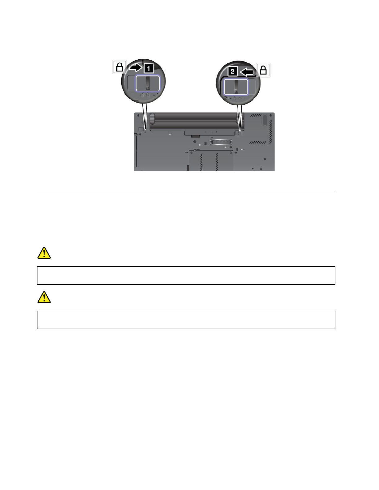
6.Slidethebatterylatchtothelockedposition.
7.Turnthecomputeroveragain.Connecttheacpoweradapterandthecablestothecomputer.
Replacingthekeyboard
Beforeyoustart,printtheseinstructions.
Youcanusethefollowingprocedurestoreplacethekeyboardwithanewone,availableasanoption.
Prerequisitesfortheprocedure
DANGER
Duringelectricalstorms,donotconnectthecabletoordisconnectitfromthetelephoneoutlet
onthewall.
DANGER
Electriccurrentfrompower,telephone,andcommunicationcablesishazardous.T oavoidshock
hazard,disconnectthecablesbeforeopeningthecoverofthisslot.
Toreplacethekeyboard,doasfollows.
Removingthekeyboard
1.Turnoffthecomputer;thendisconnecttheacpoweradapterandallcablesfromthecomputer.Waitfor
afewminutes,tilltheinsideofthecomputercools,beforeyoustartthefollowingprocedures.
2.Closethecomputerdisplay,andturnthecomputerover.
3.Removethebattery.Fordetails,refertotheinstructionsin“Removethebattery”onpage118.
120UserGuide
Page 4
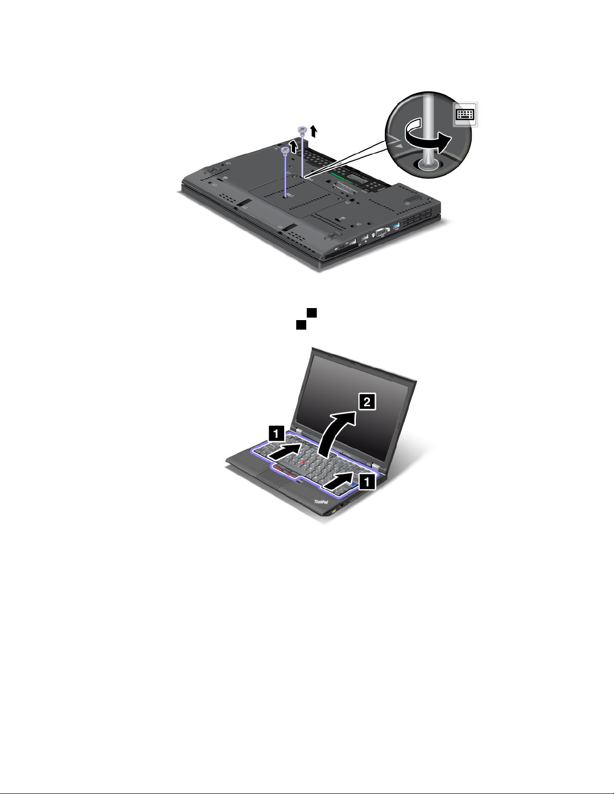
4.Loosenthetwoscrewsonthememoryslotcover,thenremovethecover.
5.Turnthecomputeroverandopenthedisplay.
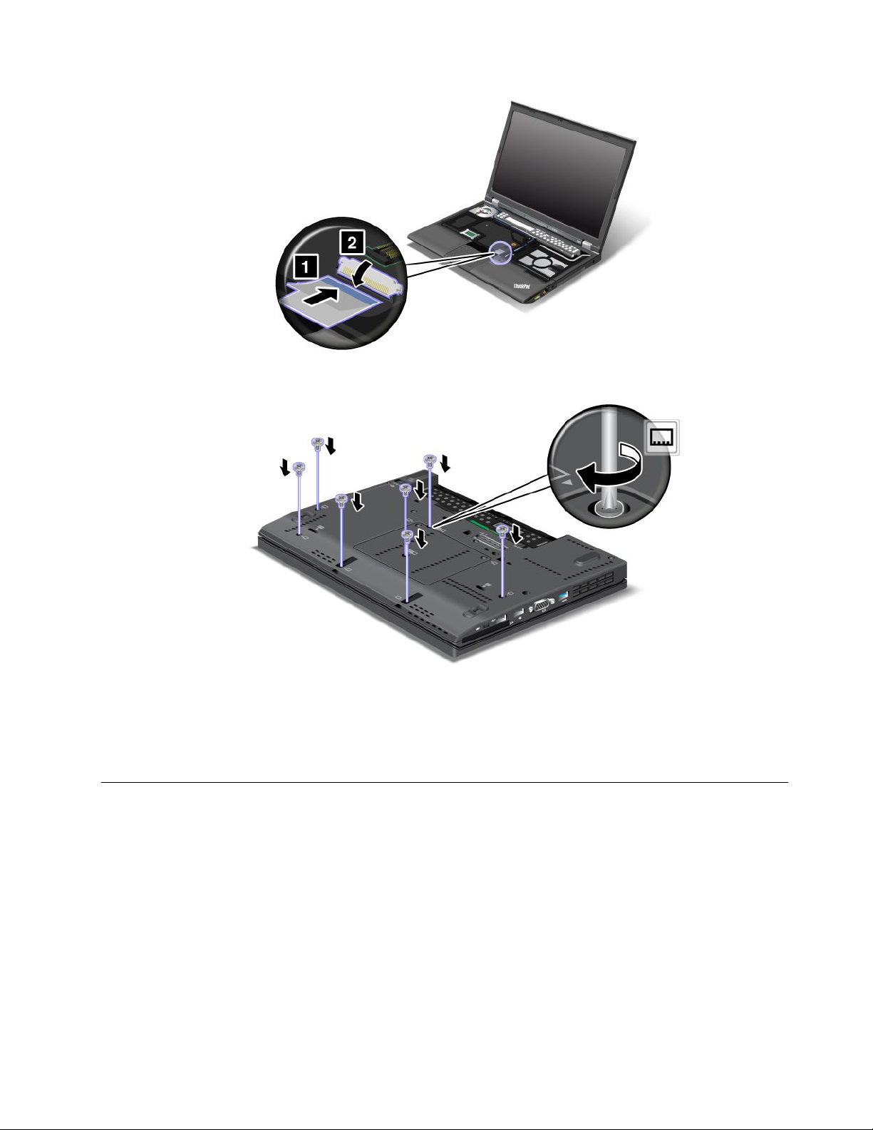
6.Pushhardinthedirectionshownbythearrows1inthedrawingtounlatchthefrontsideofthe
keyboard.Thekeyboardwillopenupslightly2.
Chapter6.Replacingdevices121
Page 5
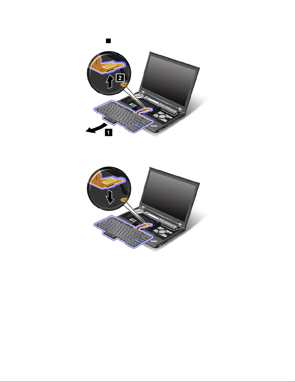
7.Carefullyliftthekeyboarduntilyoucanseehowit'sconnected.Holdthekeyboardabovethecomputer,
andthendetachtheconnector2.Nowthekeyboardhasbeenremoved.
Installingthekeyboard
1.Attachtheconnector.
122UserGuide
Page 6
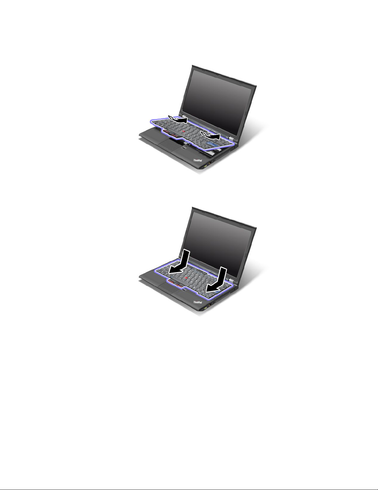
2.Insertthekeyboard.Makesurethattherearedgesofthekeyboardareundertheframeasshownby
thearrows.
3.Pressgentlyontheareasmarkedinthedrawing,andslidethekeyboardtowardyou.Makesurethatthe
edgesofthekeyboardmarkedinthedrawing,areundertheframe.
Chapter6.Replacingdevices123
Page 7
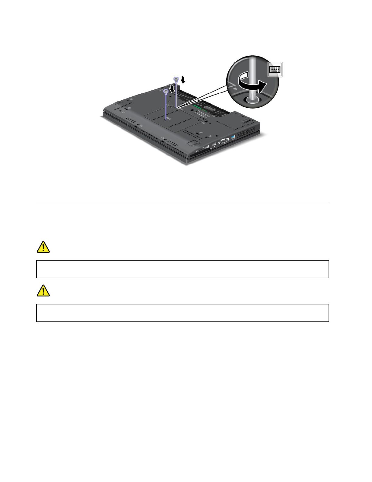
4.Putthememoryslotcoverbackinplace,closethecover,andthentightenthescrews.
5.Reinstallthebattery.Fordetails,refertotheinstructionsin“Reinstallthebattery”onpage118.
6.Turnthecomputeroveragain.Connecttheacpoweradapterandcablestothecomputer;thenturniton.
Replacingthepalmrest
Beforeyoustart,printtheseinstructions.
Prerequisitesfortheprocedure
DANGER
Duringelectricalstorms,donotconnectthecabletoordisconnectitfromthetelephoneoutlet
onthewall.
DANGER
Electriccurrentfrompower,telephone,andcommunicationcablesishazardous.T oavoidshock
hazard,disconnectthecablesbeforeopeningthecoverofthisslot.
Replacementinstructions
1.Turnoffthecomputer;thendisconnecttheacpoweradapterandallcablesfromthecomputer.Waitfor
afewminutes,tilltheinsideofthecomputercools,beforeyoustartthefollowingprocedures.
2.Closethecomputerdisplay,andturnthecomputerover.
3.Removethebattery.Formoreinformation,refertoReplacingthebattery.
4.Removethekeyboard.Formoreinformationabouthowtoremovethekeyboard,refertoReplacingthe
keyboard.
5.Removethescrewsthatsecurethepalmrest.
124UserGuide
Page 8
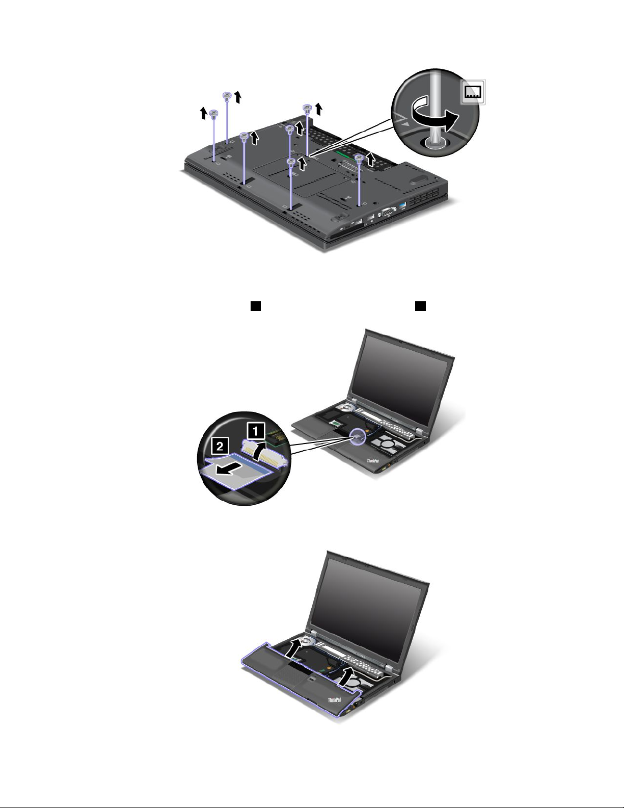
6.Turnthecomputeroverandopenthedisplay.Liftuptheleftandrighttopedgesofthepalmrestto
removeit.
7.Detachtheip-lockZIFconnector1,thenremovethepalmrestcable2.
8.Liftupandremovethepalmrest.
Chapter6.Replacingdevices125
Page 9
9.Releasethepalmrestfromthecomputer.Nowthepalmresthasbeenremoved.
Installingthepalmrest
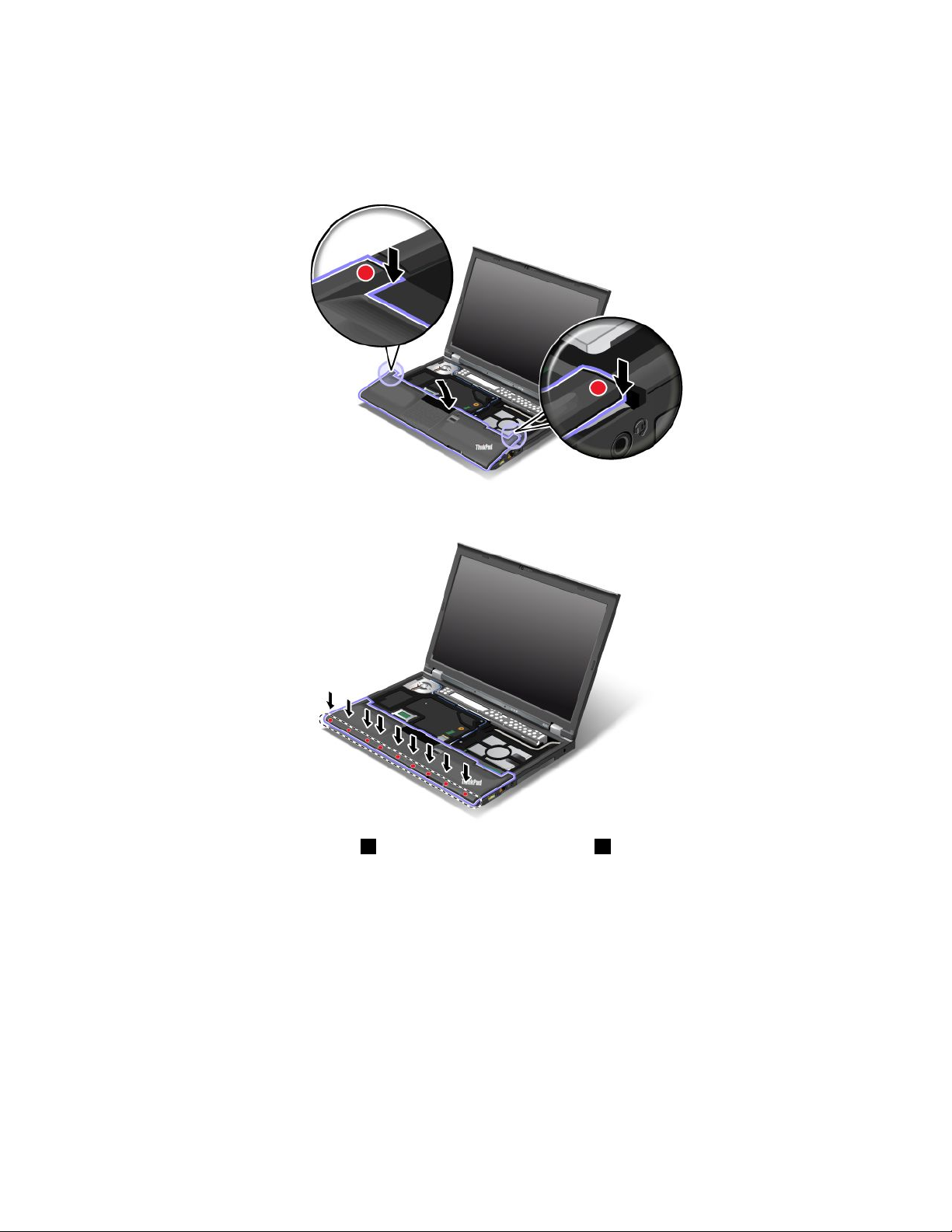
1.Attachthepalmrest,makingsurethelatchesnearthetopleftandrightedgesofthepalmrestaresecure.
2.Pushthefrontsideofthepalmrestuntilitclicksintoplace.
3.Attachtheip-lockZIFconnector1,thenpushthepalmrestcable2.
126UserGuide
Page 10
4.Reinstallthescrewsforthepalmrest.
5.Reinstallthekeyboard.Formoreinformationabouthowtoremovethekeyboard,refertoReplacingthe
keyboard.
6.Reinstallthebattery.Formoreinformation,refertoReplacingthebattery.
7.Turnthecomputeroveragain.Connecttheacpoweradapterandcablestothecomputer;thenturniton.
Replacingtheharddiskdrive
Beforeyoustart,printtheseinstructions.
YoucanreplacetheharddiskdrivewithanewonewhichcanbepurchasedfromyourLenovoresellerora
marketingrepresentative.Toreplacetheharddiskdrive,readthefollowingprerequisites.
Note:Replacetheharddiskdriveonlyifyouupgradeitorhaveitrepaired.Theconnectorsandslotofthe
harddiskdrivewerenotdesignedforfrequentchanges,ordriveswapping.
Prerequisitesfortheprocedure
Whenreplacingthedrive,besuretofollowtheprecautions.
Attention:Whenyouarehandlingaharddiskdrive:
Chapter6.Replacingdevices127
Page 11
•Donotdropthedriveorsubjectittophysicalshocks.Putthedriveonamaterial,suchassoftcloth,that
absorbsanyphysicalshocks.
•Donotapplypressuretothecoverofthedrive.
•Donottouchtheconnector.
Thedriveisverysensitive.Incorrecthandlingcancausedamageandpermanentlossofdata.
Beforeremovingtheharddiskdrive,makeabackupcopyofalltheinformationonit,andthenturnthe
computeroff.
Neverremovethedrivewhilethesystemisoperating,insleep(standby)mode,orinhibernationmode.
Toreplacetheharddiskdrive,doasfollows:
1.Turnoffthecomputer;thendisconnecttheacpoweradapterandallcablesfromthecomputer.
2.Closethecomputerdisplay,andturnthecomputerover.
3.Removethebattery.Fordetails,refertotheinstructionsin“Removethebattery”onpage118.
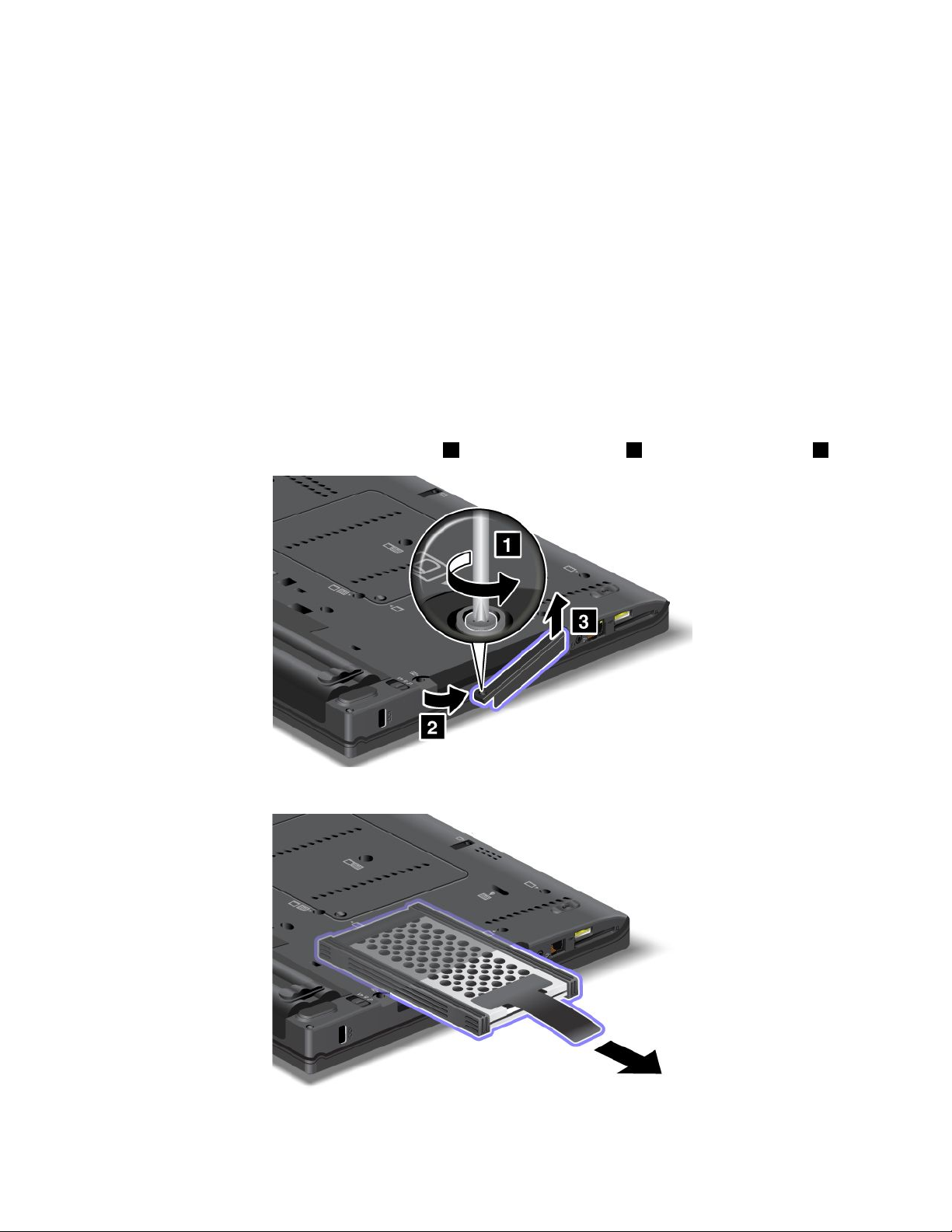
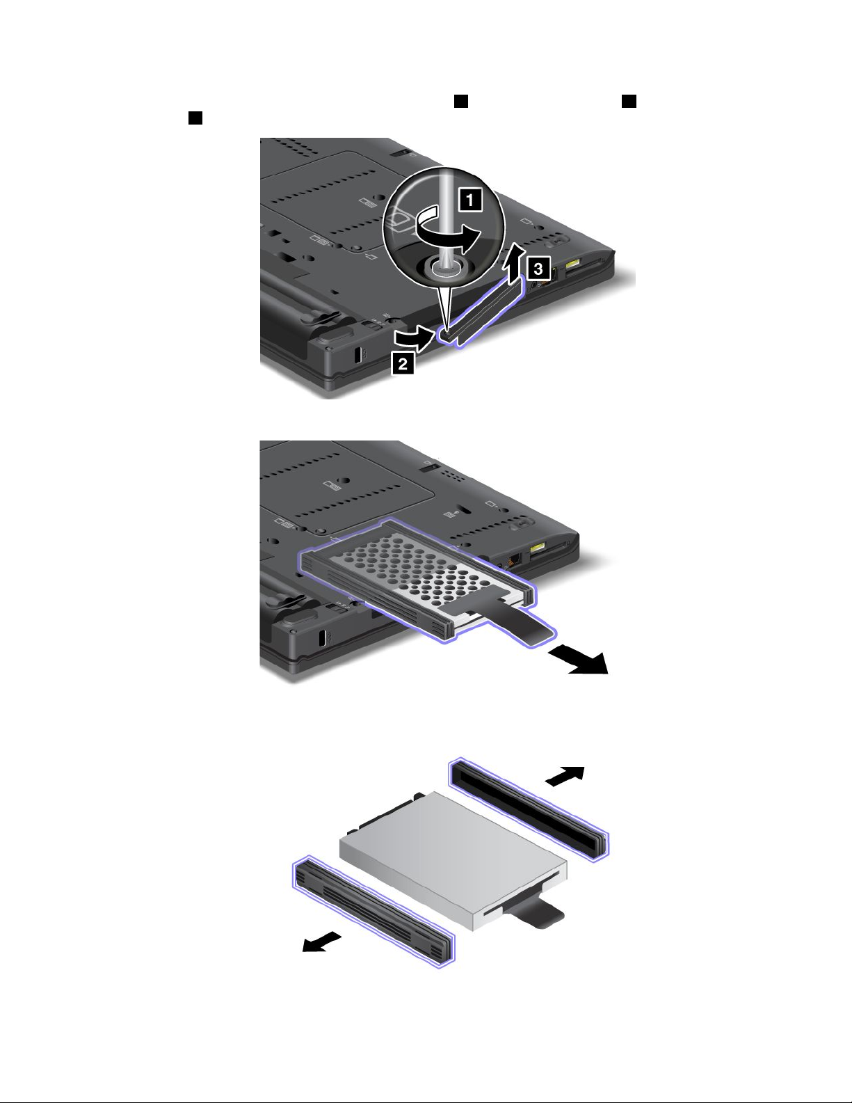
4.Removethescrewthatsecurestheslotcover1.Thenipoutthecover2andpulluptoremoveit3.
5.Removetheharddiskdrivebypullingoutthetab.
128UserGuide
Page 12
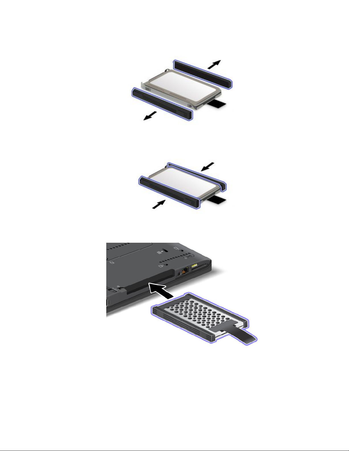
6.Detachthesiderubberrailsfromtheharddiskdrive.
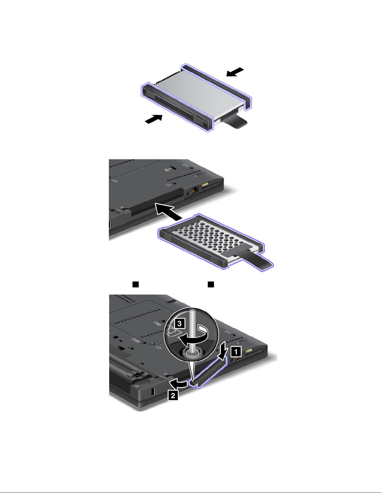
7.Attachthesiderubberrailstoanewharddiskdrive.
8.Inserttheharddiskdriveintotheharddiskdrivebay,thenpressitrmlyintoplace.
Chapter6.Replacingdevices129
Page 13
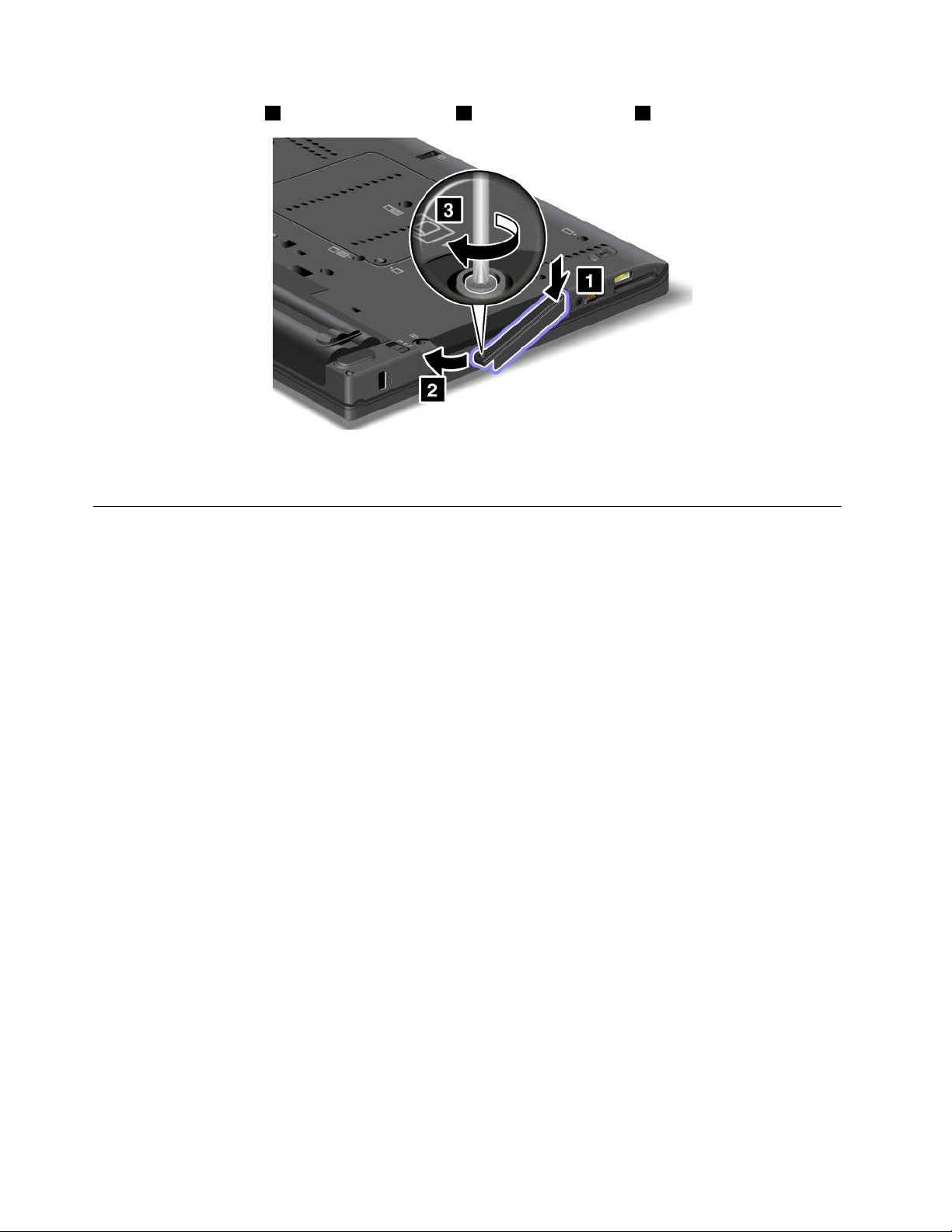
9.Inserttheslotcover1.Then,slideinthecover2andreinstallthescrew3.
10.Reinstallthebattery.Fordetails,refertotheinstructionsin“Reinstallthebattery”onpage118.
11.Turnthecomputeroveragain.Connecttheacpoweradapterandthecablestothecomputer.
Replacingthesolidstatedrive
YoucanreplacethesolidstatedrivewithanewonewhichcanbepurchasedfromyourLenovoresellerora
marketingrepresentative.Toreplacethesolidstatedrive,readthefollowingprerequisitesandselectyour
modelfromthelistbelowforinstructions.
Note:Replacethesolidstatedriveonlyifyouneedtohaveitrepaired.Theconnectorsandslotofthesolid
statedrivewerenotdesignedforfrequentchanges,ordriveswapping.
Prerequisitesfortheprocedure
Whenreplacingthedrive,besuretofollowtheprecautions.
Attention:Whenyouarehandlingasolidstatedrive:
•Donotdropthedriveorsubjectittophysicalshocks.Putthedriveonamaterial,suchassoftcloth,that
absorbsanyphysicalshocks.
•Donotapplypressuretothecoverofthedrive.
•Donottouchtheconnector.
Thedriveisverysensitive.Incorrecthandlingcancausedamageandpermanentlossofdata.
Beforeremovingthesolidstatedrive,makeabackupcopyofalltheinformationonit,andthenturnthe
computeroff.
Neverremovethedrivewhilethesystemisoperating,insleep(standby)mode,orinhibernationmode.
Replacementinstructions
Toreplacethesolidstatedrive,doasfollows:
1.Turnoffthecomputer;thendisconnecttheacpoweradapterandallcablesfromthecomputer.
2.Closethecomputerdisplay,andturnthecomputerover.
3.Removethebattery.Formoreinformation,referto“Replacingthebattery”onpage118.
130UserGuide
Page 14
4.Removethescrewthatsecuresthesolidstatedrive1.Thenipoutthecover2andpullupto
removeit3.
5.Removethesolidstatedrivebypullingoutthetab.
6.Detachthesidespacerrailsfromtheharddiskdrive.
Chapter6.Replacingdevices131
Page 15
7.Attachthesidespacerrailstoanewharddiskdrive.
8.Insertthesolidstatedriveintotheharddiskdrivebay,thenpressitrmlyintoplace.
9.Reinstallthecoverofthebay1,thenreinstallthescrew2.
10.Reinstallthebattery.Formoreinformationabouthowtoreinstallthebattery,referto“Replacingthe
battery”onpage118
11.Turnthecomputeroveragain.Connecttheacpoweradapterandthecablestothecomputer.
.
132UserGuide
Page 16

InstallingandreplacingthePCIExpressMiniCardforwireless
LAN/WiMAXconnection
Beforeyoustart,printtheseinstructions.
YourcomputerhasaPCIExpressMiniCardslotforconnectiontoawirelessLAN/WiMAX.ToreplacethePCI
ExpressMiniCardwithanewone,readthefollowingprerequisites.
Prerequisitesfortheprocedure
DANGER
Duringelectricalstorms,donotconnectthecabletoordisconnectitfromthetelephoneoutlet
onthewall.
DANGER
Electriccurrentfrompower,telephone,andcommunicationcablesishazardous.T oavoidshock
hazard,disconnectthecablesbeforeopeningthecoverofthisslot.
Attention:BeforeyoustartinstallingaPCIExpressMiniCard,touchametaltableoragroundedmetal
object.Thisactionreducesanystaticelectricityfromyourbody.Thestaticelectricitycoulddamagethecard.
YourcomputerhasaPCIExpressMiniCardslotforconnectiontoawirelessLAN/WiMAX.Toreplacethe
PCIExpressMiniCardwithanewone,followtheprocedurebelow.
ReplacingaPCIExpressMiniCardwithtwoconnectors
1.Turnoffthecomputer;thendisconnecttheacpoweradapterandallcablesfromthecomputer.Waitfor
afewminutes,tilltheinsideofthecomputercools,beforeyoustartthefollowingprocedures.
2.Closethecomputerdisplay,andturnthecomputerover.
3.Removethebattery.Fordetails,refertotheinstructionsin“Removethebattery”onpage118.
4.Removethepalmrest.Fordetails,refertotheinstructionsin“Removethepalmrest”onpage124.
Chapter6.Replacingdevices133
Page 17

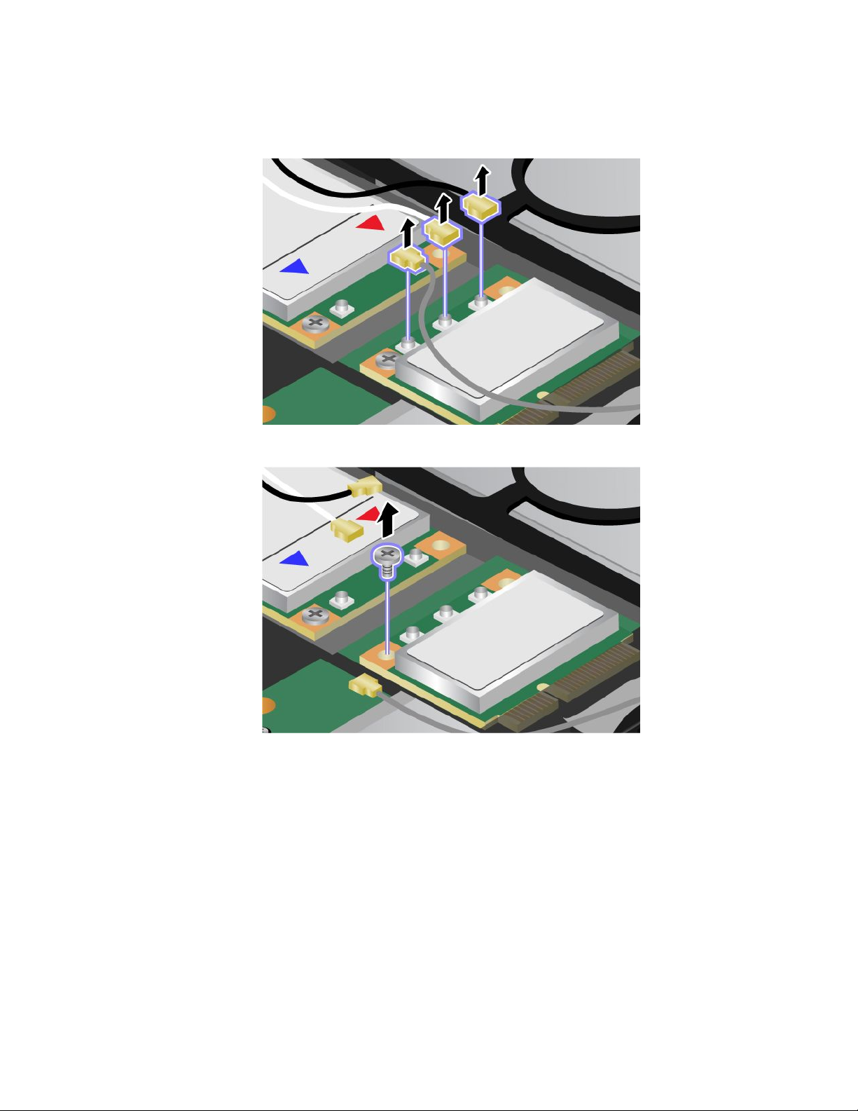
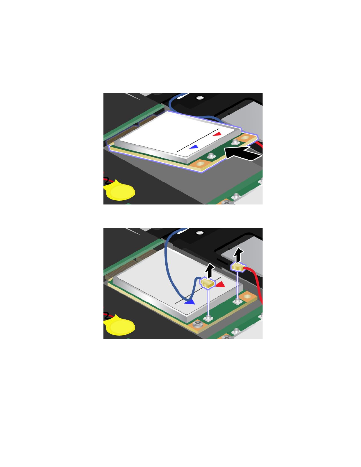
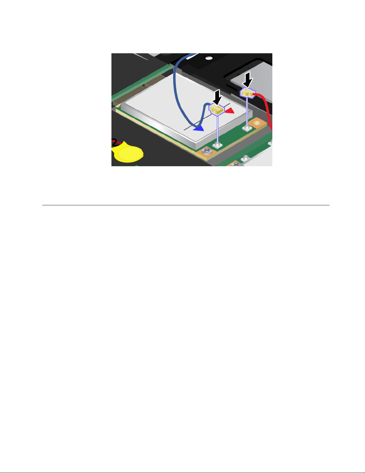
5.Ifatoolforremovingconnectorsisincludedinthepackagewiththenewcard,useittodisconnectthe
cablesfromthecard.Ifnosuchtoolisincluded,disconnectthecablesbypickinguptheconnectors
withyourngersandgentlyunpluggingthem.
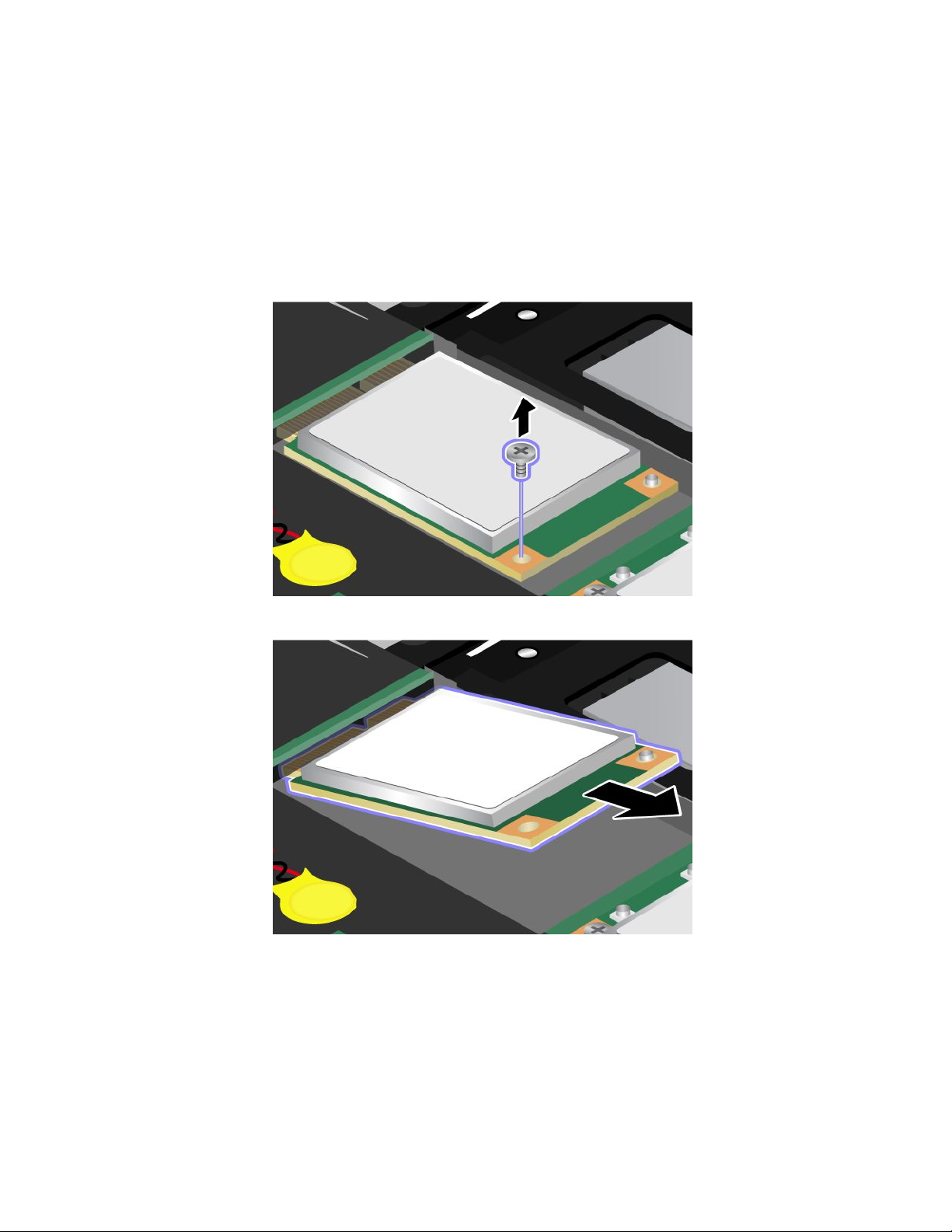
6.Removethescrew.Thecardpopsup.
134UserGuide
Page 18
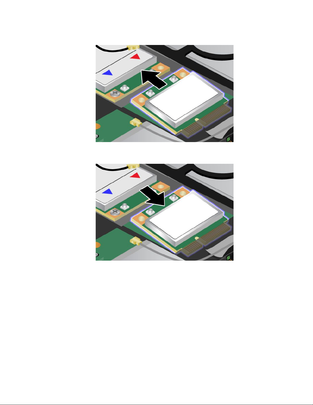
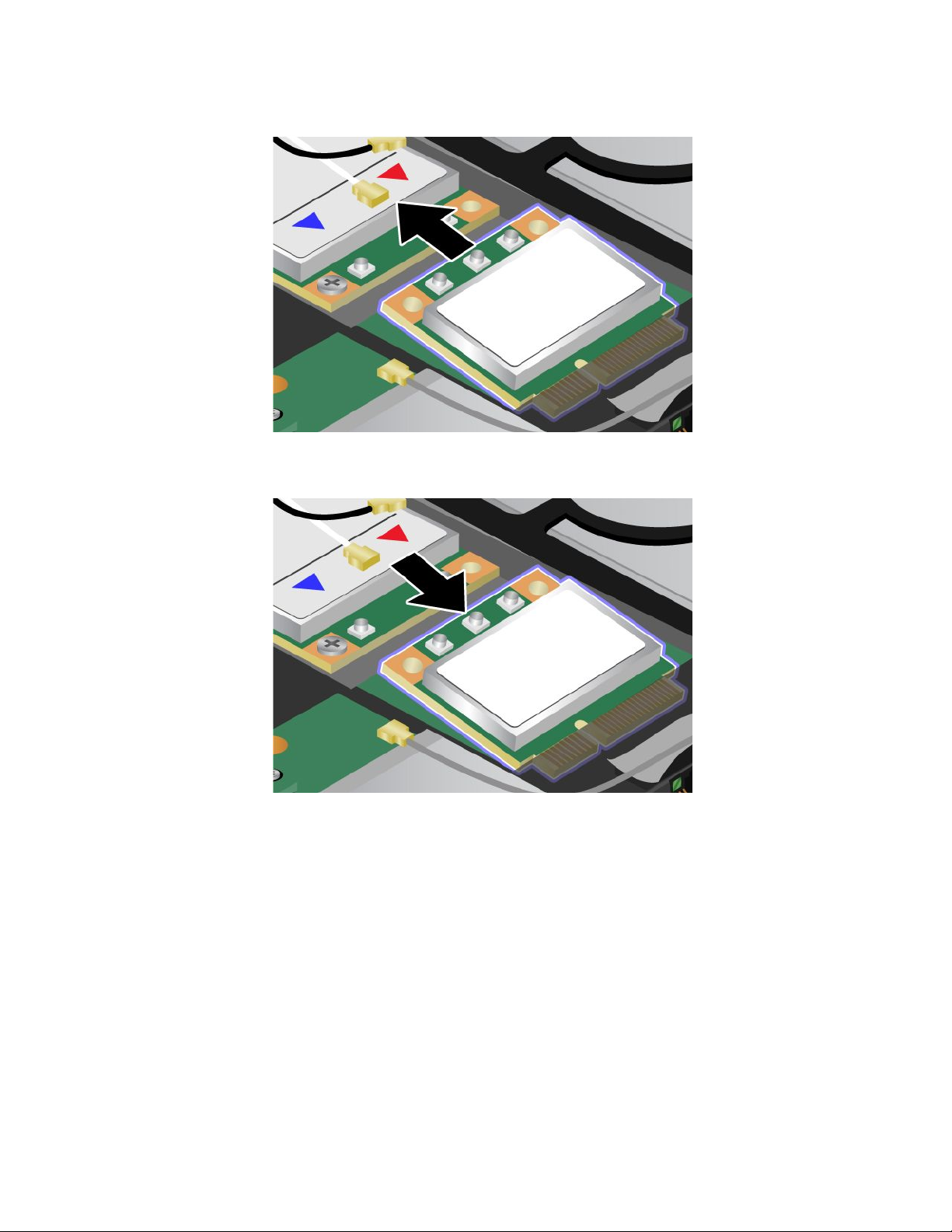
7.Removethecard.
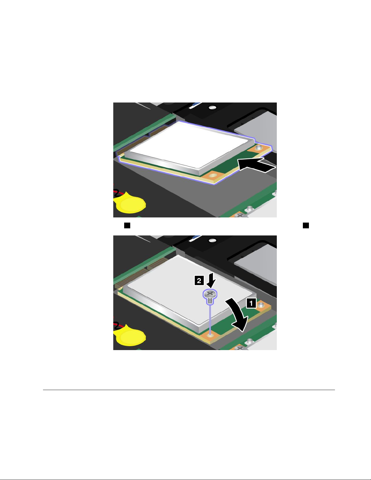
8.AlignthecontactedgeofthenewPCIExpressMiniCardwiththecorrespondingsocketcontactofthe
computer.
Chapter6.Replacingdevices135
Page 19
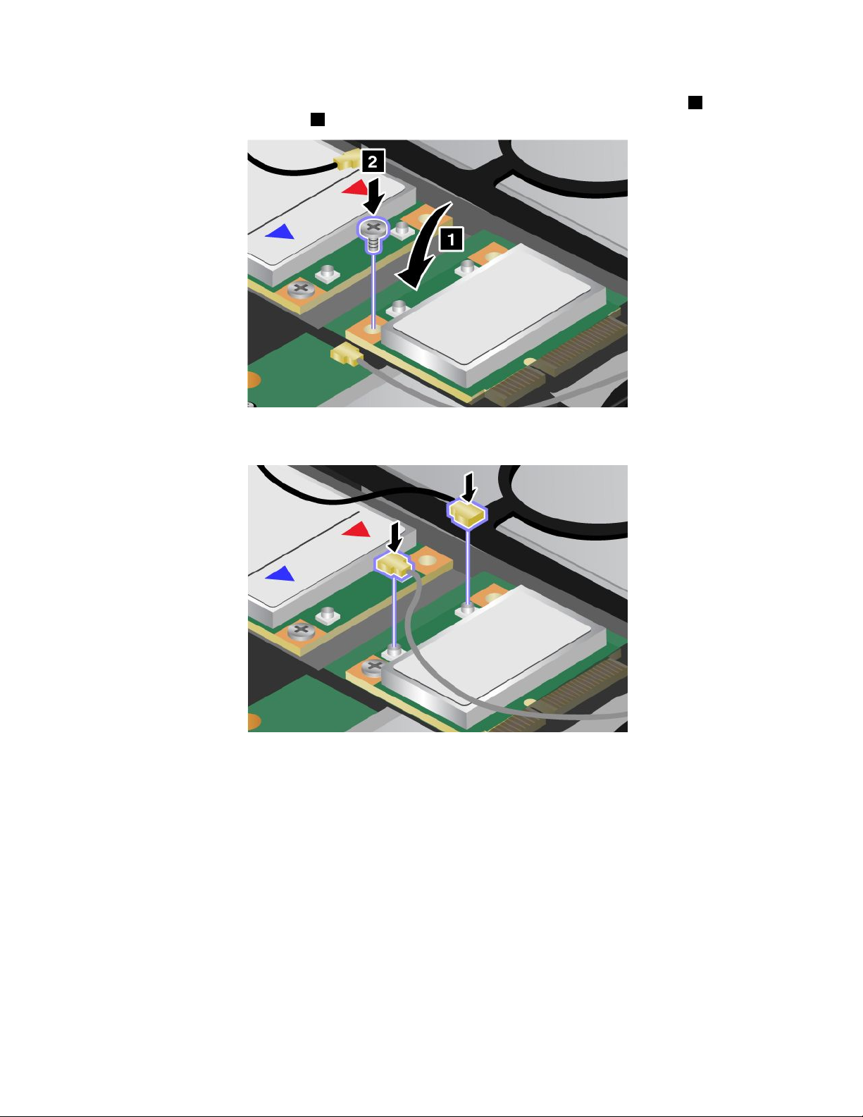
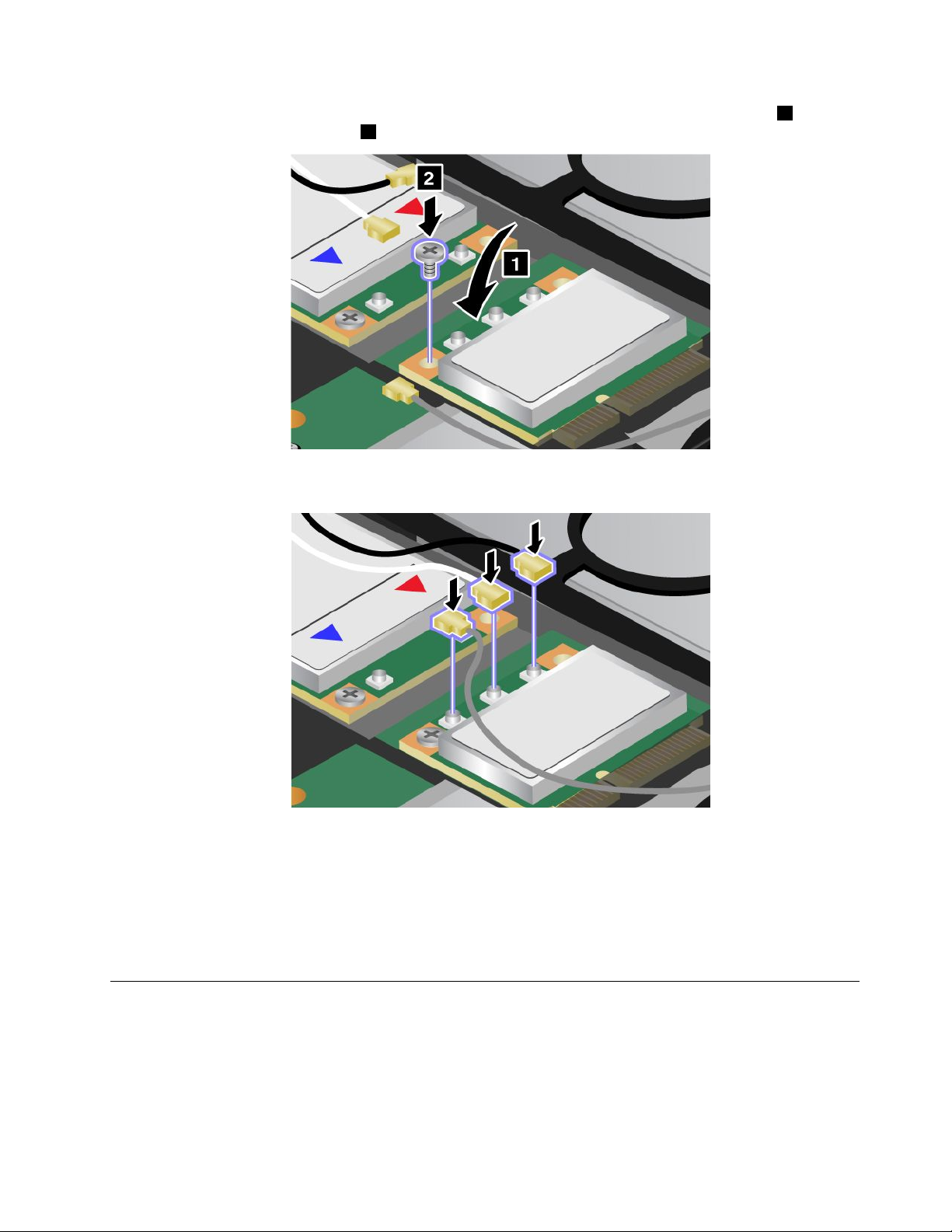
9.Pivotthecarduntilyoucansnapitintoplacebypressingtheuppersideoftheconnectors1,and
securethecardwiththescrew2.
10.ConnectthecablestothenewPCIExpressMiniCard.Besuretoattachthegraycabletotheconnector
marked“MAIN”or“M”onthecard,andtheblackcabletotheconnectormarked“AUX”or“A.”
Note:IfthenewPCIExpressMiniCardhasthreeconnectors,besuretoattachthegraycabletothe
connectormarked“TR1”onthecard,andtheblackcabletotheconnectormarked“TR2”.Ifyouattach
eithercabletothecenterconnector,theconnectionspeedwillbelower.
11.Reinstallthepalmrest.Fordetails,refertotheinstructionsin“Reinstallthepalmrest”onpage124.
12.Reinstallthebattery.Fordetails,refertotheinstructionsin“Reinstallthebattery”onpage118.
13.Turnthecomputeroveragain.Connecttheacpoweradapterandcablestothecomputer;thenturniton.
ReplacingaPCIExpressMiniCardwiththreeconnectors
1.Turnoffthecomputer;thendisconnecttheacpoweradapterandallcablesfromthecomputer.Waitfor
afewminutes,tilltheinsideofthecomputercools,beforeyoustartthefollowingprocedures.
2.Closethecomputerdisplay,andturnthecomputerover.
3.Removethebattery.Fordetails,refertotheinstructionsin“Removethepalmrest”onpage124.
4.Removethekeyboard.Fordetails,refertotheinstructionsin“Removethekeyboard”onpage120.
136UserGuide
Page 20
5.Ifatoolforremovingconnectorsisincludedinthepackagewiththenewcard,useittodisconnectthe
cablesfromthecard.Ifnosuchtoolisincluded,disconnectthecablesbypickinguptheconnectors
withyourngersandgentlyunpluggingthem.
6.Removethescrew.Thecardpopsup.
Chapter6.Replacingdevices137
Page 21
7.Removethecard.
8.AlignthecontactedgeofthenewPCIExpressMiniCardwiththecorrespondingsocketcontactofthe
computer.
138UserGuide
Page 22
9.Pivotthecarduntilyoucansnapitintoplacebypressingtheuppersideoftheconnectors1,and
securethecardwiththescrew2.
10.ConnectthecablestothenewPCIExpressMiniCard.Besuretoattachthegraycabletotheconnector
marked“MAIN”or“M”onthecard,andtheblackcabletotheconnectormarked“AUX”or“A.”
Note:IfthenewPCIExpressMiniCardhasthreeconnectors,besuretoattachthegraycabletothe
connectormarked“TR1”onthecard,andtheblackcabletotheconnectormarked“TR2”.Ifyouattach
eithercabletothecenterconnector,theconnectionspeedwillbelower.
11.Reinstallthekeyboard.Fordetails,refertotheinstructionsin“Reinstallthepalmrest”onpage124.
12.Reinstallthebattery.Fordetails,refertotheinstructionsin“Reinstallthebattery”onpage118.
13.Turnthecomputeroveragain.Connecttheacpoweradapterandcablestothecomputer;thenturniton.
InstallingandreplacingthePCIExpressMiniCardforwirelessWAN
connection
Beforeyoustart,printtheseinstructions.
SomeThinkPadmodelshaveaPCIExpressMiniCardslotforconnectiontoawirelessWAN.Toreplacethe
PCIExpressMiniCardwithanewone,readthefollowingprerequisites.
Chapter6.Replacingdevices139
Page 23
Prerequisitesfortheprocedure
DANGER
Duringelectricalstorms,donotconnectthecabletoordisconnectitfromthetelephoneoutlet
onthewall.
DANGER
Electriccurrentfrompower,telephone,andcommunicationcablesishazardous.T oavoidshock
hazard,disconnectthecablesbeforeopeningthecoverofthisslot.
Attention:BeforeyoustartinstallingaPCIExpressMiniCard,touchametaltableoragroundedmetal
object.Thisactionreducesanystaticelectricityfromyourbody.Thestaticelectricitycoulddamagethecard.
IfaWirelessWANisavailableinyourcomputer,toreplacethePCIExpressMiniCard,doasfollows.
1.Turnoffthecomputer;thendisconnecttheacpoweradapterandallcablesfromthecomputer.Waitfor
afewminutes,tilltheinsideofthecomputercools,beforeyoustartthefollowingprocedures.
2.Closethecomputerdisplay,andturnthecomputerover.
3.Removethebattery.Fordetails,refertotheinstructionsin“Removethebattery”onpage118.
4.Removethepalmrest.Fordetails,refertotheinstructionsin“Removethepalmrest”onpage124.
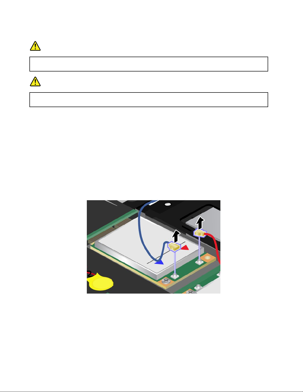
5.Ifatoolforremovingconnectorsisincludedinthepackagewiththenewcard,useittodisconnectthe
cablesfromthecard.Ifnosuchtoolisincluded,disconnectthecablesbypickinguptheconnectors
withyourngersandgentlyunpluggingthem.
Note:Dependingonthesystemcongurationofyourcomputer,thecardmayhaveonlyoneconnector.
140UserGuide
Page 24

6.Removethescrew.Thecardpopsup.
7.Removethecard.
Chapter6.Replacingdevices141
Page 25
8.AlignthecontactedgeofthenewPCIExpressMiniCardwiththecorrespondingsocket.
Notes:
•YoucanalsoreplacethePCIExpressMiniCardforWirelessWANwithanmSATAsolidstatedrive.
•ToinstallanewmSATAsolidstatedrive,referto“InstallingandreplacingthemSATAsolidstate
drive”onpage143.
9.Pivotthecarduntilyoucansnapitintoplacebypressingtheuppersideofeachconnector.Secure
thecardwiththescrew.
Note:Dependingonthesystemcongurationofyourcomputer,thecardmayhaveonlyoneconnector.
142UserGuide
Page 26
10.ConnectthecablestothenewPCIExpressMiniCard.
11.Reinstallthekeyboard.Fordetails,refertotheinstructionsin“Reinstallthepalmrest”onpage124.
12.Reinstallthebattery.Fordetails,refertotheinstructionsin“Reinstallthebattery”onpage118.
13.Turnthecomputeroveragain.Connecttheacpoweradapterandcablestothecomputer;thenturniton.
InstallingandreplacingthemSAT Asolidstatedrive
Beforeyoustart,printtheseinstructions.
SomeThinkPadmodelshaveanmSATAsolidstatedrive.Y oucanreplacethemSATAsolidstatedrivewitha
newonewhichcanbepurchasedfromyourLenovoreselleroramarketingrepresentative.Toreplacethe
mSATAsolidstatedrive,readthefollowingprerequisites.
Notes:
•YoucanalsoreplacethemSATAsolidstatedrivewithaWirelessPCIExpressMiniCardforWirelessWAN.
•ReplacethemSATAsolidstatedriveonlyifyouneedtohaveitrepaired.
Prerequisitesfortheprocedure
WhenreplacingthemSATAsolidstatedrive,besuretofollowtheprecautions.
Attention:WhenyouarehandlinganmSATAsolidstatedrive:
•DonotdropthemSATAsolidstatedriveorsubjectittophysicalshocks.PutthemSA T Asolidstatedrive
onamaterial,suchassoftcloththatabsorbsanyphysicalshocks.
•DonotapplypressuretothecoverofthemSATAsolidstatedrive.
ThemSATAsolidstatedriveisverysensitive.Incorrecthandlingcancausedamageandpermanentlossof
data.
BeforeremovingthemSATAsolidstatedrive,makeabackupcopyofalltheinformationonit,andthen
turnthecomputeroff.
NeverremovethemSATAsolidstatedrivewhilethesystemisoperating,insleep(standby)mode,orin
hibernationmode.
Chapter6.Replacingdevices143
Page 27
IfanmSAT Asolidstatedriveisavailableinyourcomputer,toreplacethemSATAsolidstatedrive,do
asfollows.
1.Turnoffthecomputer;thendisconnecttheacpoweradapterandallcablesfromthecomputer.Waitfor
afewminutes,tilltheinsideofthecomputercools,beforeyoustartthefollowingprocedures.
2.Closethecomputerdisplay,andturnthecomputerover.
3.Removethebattery.Fordetails,refertotheinstructionsin“Removethebattery”onpage118.
4.Removethepalmrest.Fordetails,refertotheinstructionsin“Removethepalmrest”onpage124.
5.Removethescrew.Thecardpopsup.
6.Removethecard.
144UserGuide
Page 28
7.AlignthecontactedgeofanewmSATAsolidstatedrivewiththecorrespondingsocket.
Notes:
•YoucanalsoreplacethemSATAsolidstatedrivewithaWirelessPCIExpressMiniCardforWireless
WAN.
•ToinstallanewPCIExpressMiniCard,referto“InstallingandreplacingthePCIExpressMiniCard
forwirelessWANconnection”onpage139
.
8.Pivotthecarddownward1untilyoucansnapitintoplace.Securethecardwiththescrew2.
9.Reinstallthekeyboard.Fordetails,refertotheinstructionsin“Reinstallthepalmrest”onpage124.
10.Reinstallthebattery.Fordetails,refertotheinstructionsin“Reinstallthebattery”onpage118.
11.Turnthecomputeroveragain.Connecttheacpoweradapterandcablestothecomputer;thenturniton.
Replacingmemory
Beforeyoustart,printtheseinstructions.
Prerequisitesfortheprocedure
Whenreplacingthememory,besuretofollowtheprecautions:
Chapter6.Replacingdevices145
Page 29
Note:Theoperatingspeedofthememorymoduledependsonthesystemcongurationofyourcomputer
anditscombinationwiththememorymoduleinstalledonyourcomputer.Insomeconditions,thememoryin
yourcomputermaynotbeabletooperateatthemaximumspeed.
Attention:Beforeyoustartinstallingamodule,touchametaltableoragroundedmetalobject.Thisaction
reducesanystaticelectricityfromyourbody.ThestaticelectricitycoulddamagetheSO-DIMM.
ToreplacetheSO-DIMM,dothefollowing:
1.Turnoffthecomputer;thendisconnecttheacpoweradapterandallcablesfromthecomputer.
2.Closethecomputerdisplay,andturnitover.
3.Removethebattery.Referto“Replacingthebattery”onpage118fordetailsabouthowtoreplacing
thebattery.
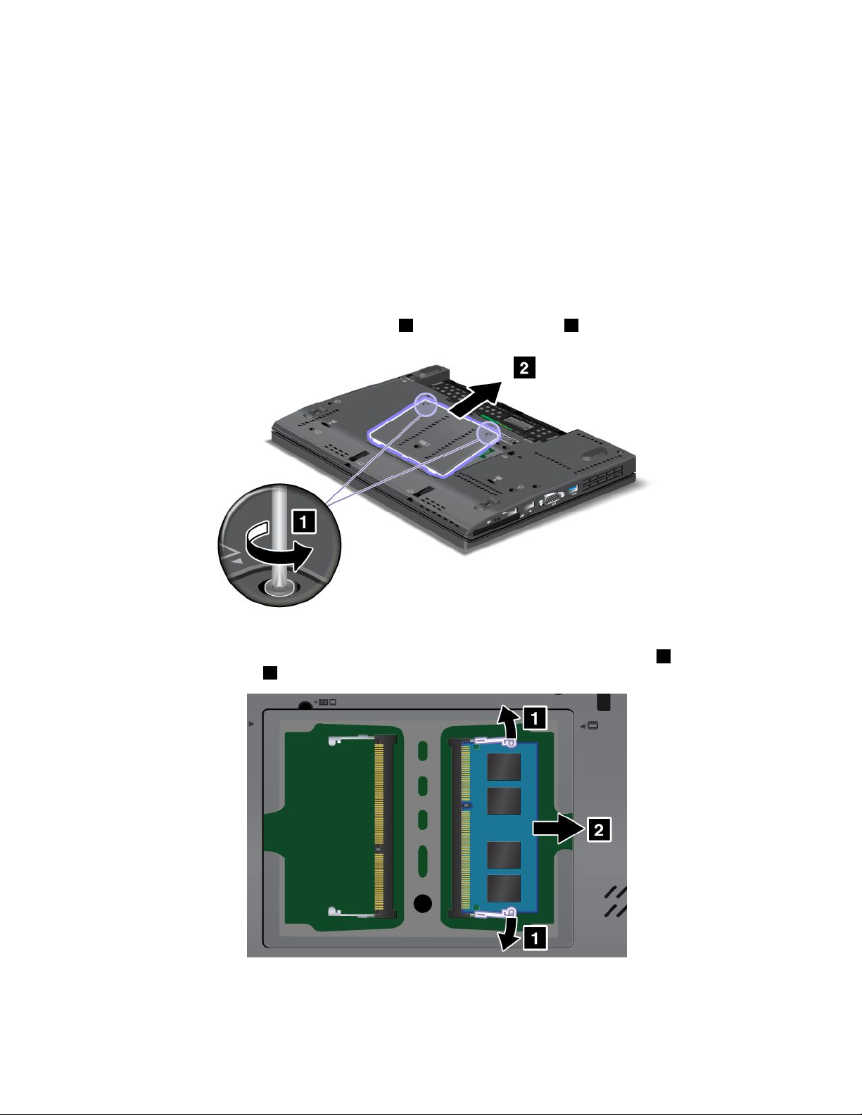
4.Loosenthescrewsonthememoryslotcover1,thenremovethecover2.
IfthetwoSO-DIMMsarealreadyinthememoryslots,removeanSO-DIMMtomakeroomforthe
newonebypressingoutonthelatchesonbothedgesofthesocketatthesametime
tosaveitforfutureuse2.
5.FindthenotchonthecontactedgesideoftheSO-DIMMyouareinstalling.
Attention:ToavoiddamagingtheSO-DIMM,donottouchitscontactedge.
1.Besure
146UserGuide
Page 30
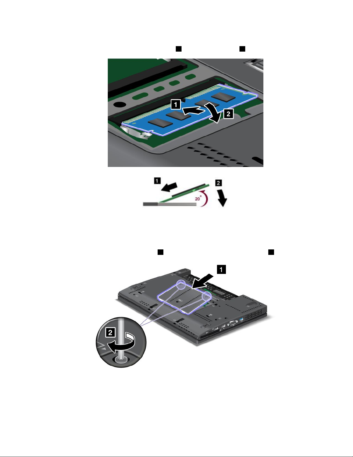
6.WiththenotchedendoftheSO-DIMMtowardthecontactedgesideofthesocket,inserttheSO-DIMM
intothesocketatanangleofabout20degrees1;thenpressitinrmly2.
Note:Ifyouinstallamemorymoduleinonlyoneofthetwomemoryslots,installitinthelowerslot.
7.PivottheSO-DIMMdownwarduntilitsnapsintoplace.
8.MakesurethattheSO-DIMMisrmlyxedintheslotandcannotbemovedeasily.
9.Putthememoryslotcoverbackinplace1,closethecover,andtightenthescrews2.
10.Putthebatterybackinplace,turnthecomputeroveragain,andreconnectthecables.Forinformation
abouthowtoreplacethebattery,referto“Replacingthebattery”onpage118.
TomakesurethattheSO-DIMMisinstalledcorrectly,doasfollows:
1.Turnthecomputeron.
Chapter6.Replacingdevices147
Page 31

2.Whenthelogoscreenisdisplayed,presstheF1key.TheThinkPadSetupopens.The“Installed
memory”itemshowsthetotalamountofmemoryinstalledinyourcomputer.
ReplacingtheSIMcard
Beforeyoustart,printtheseinstructions.
YourcomputermayrequireaSIM(SubscriberIdenticationModule)cardtoestablishawirelessWAN(Wide
AreaNetwork)connections.Dependingonthecountryofdelivery,theSIMcardmaybealreadyinstalledin
yourcomputerorwillbepartoftheshippingcontentsthatcamewithyourcomputer.
IfyoundtheSIMcardsincludedintheshippingcontents,adummycardisinstalledintheSIMcard
slot.Thenproceedtothefollowinginstructions.
Ifyoundthedummycardintheshippingcontents,theSIMcardisalreadyinstalledintheSIMcard
slot,andnofurtherinstallationisneeded.
Note:TheSIMcardisidentiedbytheICchipmountedononesideofthecard.
ToreplacetheSIMcard,doasfollows.
1.Turnoffthecomputer;thendisconnecttheacpoweradapterandallcablesfromthecomputer.
2.Closethecomputerdisplay,andturnitover.
3.Removethebattery.Fordetails,refertotheinstructionsin“Removethebattery”onpage118.
4.FindtheSIMcardslotinsidetheopenbatterycompartment.Removethecard.
148UserGuide
Page 32

5.InserttheSIMcardrmlyintotheslot.
Note:MakesurethatyouinserttheSIMcardallthewayintotheslot.
6.Putthebatterybackinplace.Formoredetails,referto“Replacingthebattery”onpage118.
7.Turnthecomputeroveragain,andreconnectthecables.
Chapter6.Replacingdevices149
Page 33

150UserGuide
Page 34

Chapter7.Enhancingyourcomputer
Thissectionprovidesinformationoninstallingdevicesandtakingadvantageofyourcomputer's
high-technologyfeatures.
•“FindingThinkPadoptions”onpage151
•“ThinkPadX220UltraBase”onpage151
•“ThinkPadPortReplicatorSeries3,ThinkPadMiniDockSeries3,andThinkPadMiniDockPlusSeries
3”onpage161
FindingThinkPadoptions
Ifyouwanttoexpandthecapabilitiesofyourcomputer,Lenovohasanumberofhardwareaccessoriesand
upgradestomeetyourneeds.Optionsincludememory,storage,modems,networkingadapters,docking
stationsandportreplicators,batteries,poweradapters,printers,scanners,keyboards,mice,andmore.
YoucanshopatLenovo24hoursaday,7daysaweekdirectlyovertheWorldWideWeb.Allyouneedisan
Internetconnectionandacreditcard.
ToshopatLenovo,goto:
http://www.lenovo.com/accessories/services/index.html
ThinkPadX220UltraBase
YourThinkPadX220,X220i,X220T ablet,andX220iTabletsupporttheThinkPadX220UltraBase.
AfteryouattachyourcomputertotheThinkPadX220UltraBase,youcanuseitsconnectorsinplaceof
thecomputer's.
WhenthecomputerisattachedtotheThinkPadX220UltraBase,neverpickuptheassemblybytakinghold
ofthecomputeralone.Alwaysholdthewholeassembly.
FormoredetailsabouttheThinkPadX220UltraBase,refertothefollowing:
•ThinkPadX220Ultrabasetopview
•ThinkPadX220Ultrabasebottomview
•“AttachingaThinkPadX220Ultrabase”onpage153
•“DetachingaThinkPadX220Ultrabase”onpage155
•Securityfeature
©CopyrightLenovo2011
151
Page 35

ThinkPadX220Ultrabasetopview
1ThedockingconnectorisusedforattachingtheThinkPadcomputertotheThinkPadX220UltraBase.
2ThepowerjackiswhereyouconnecttheACadapter.
3TheEthernetconnectorisforconnectingtheThinkPadX220UltraBasetoaLAN.
4TheDisplayPortconnectorisforconnectingaDisplayPort-compatibledisplaydevice.
5TheMonitorconnectorisforattachinganexternalmonitororaprojectortoyourcomputer.
6Theheadphonejack,ajack1/8inch(3.5mm)indiameter,isforconnectinganexternalheadphone.
7Themicrophonejack,ajack1/8inch(3.5mm)indiameter,isforconnectinganexternalmicrophone.
8TheUniversalSerialBus(USB)connectorisforconnectingthedevicesthatconformtotheUSB
interface.
9Thesecuritykeyholeisforlockingthedock.
10Thesystemlockkeyisforlockingtheejectbutton.
11Thebayisforopticaldiskdriveorsecondharddiskdrive.
152UserGuide
Page 36

ThinkPadX220Ultrabasebottomview
1Bypressingtheejectrequestbutton,youcantelltheoperatingsystemtogetreadyforundocking.
2Thedockingindicatorisredwhenyourcomputerisdocked.Itblinkswhentheejectrequestbutton
ispressed.
3TheejectleverdetachesyourcomputerfromtheThinkPadX220UltraBase.
4Theholesareforthesystemspeakers.
AttachingaThinkPadX220Ultrabase
Attention:DisconnecttheACpowerfromyourcomputerbeforeyouattachtheThinkPadX220UltraBase.
TheACadapterconnectorwillbedamagedifitremainsconnectedtothecomputerduringtheattachment
YoucanhotattachorwarmattachthecomputertotheThinkPadX220UltraBase.Hotattachisattachingthe
computertotheThinkPadX220UltraBasewhileinoperatingmode;warmattachisattachingthecomputer
totheThinkPadX220UltraBasewhileinsleep(standby)mode.
Indoingahot-orwarm-attach,observethefollowing:
•Forhot-attaching:ThedockingindicatoroftheThinkPadX220UltraBaseshouldturnonafterafew
seconds.
•Forwarm-attaching:Whenthecomputerreturnsfromsleep(standby)mode,thedockingindicator
oftheThinkPadX220UltraBaseshouldturnon.
ToattachyourcomputertoaThinkPadX220Ultrabase,dothefollowing:
Chapter7.Enhancingyourcomputer153
Page 37

1.MakesurethatthesystemlockkeyoftheThinkPadX220UltraBaseisintheunlocked(vertical)position.
2.AlignthefrontofthecomputerwiththefrontoftheThinkPadX220UltraBase.
154UserGuide
Page 38

3.MakesurethattheguidesoftheThinkPadX220UltraBasealignwiththeholesofthecomputer1.Then
putthecomputerinplace2.Thedockingindicatorlights.
4.WhenthecomputerisalreadydockedtotheThinkPadX220UltraBase,youcanstartthecomputer.
Note:Youcanturnthekeyclockwisetolockit.Then,keepthesecuritykeyinasafeplace.Donotlosethis
key;otherwise,youwillbeunabletodetachthecomputerfromtheThinkPadX220UltraBase.
DetachingaThinkPadX220Ultrabase
Attention:DonotdetachyourcomputerfromtheThinkPadX220UltraBasewhilethedockingindicatorof
theThinkPadX220UltraBaseisblinkingoron.Waituntilthedockingindicatorturnsoff.Detachingwhilethe
indicatorisblinkingoroncausesthesystemtobeep,andthecomputermayhalt.
YoucanhotdetachorwarmdetachthecomputerfromtheThinkPadX220UltraBase.Hotdetachis
detachingthecomputerfromtheThinkPadX220UltraBasewhileinoperatingmode;warmdetachis
detachingthecomputerfromtheThinkPadX220UltraBasewhileinsleep(standby)mode.
Toperformahot-detach,followthestepsbelow:
ForWindows7andWindowsVista:
Chapter7.Enhancingyourcomputer155
Page 39

1.ClickStart,andthenpresstherightarrowbutton.
2.SelectUndock.
3.MakesurethatthedockingindicatoroftheThinkPadX220UltraBaseisoff.
ForWindowsXP:
1.SelecttheUndockComputerintheStartmenu.
2.MakesurethatthedockingindicatoroftheThinkPadX220UltraBaseisoff.
Note:DetachingtheUltraBasesuddenlywhilethecomputerisoperatingwithoutperformingtheprocedure
abovemaycausethesystemtomalfunctionorhang.
Toperformawarm-detach,presstheejectrequestbuttonoftheThinkPadX220UltraBase.Thesystemwill
thenresumewithanOKmessage.MakesurethatthedockingindicatoroftheThinkPadX220UltraBaseis
off.Thecomputerwillre-entersleep(standby)mode.
Ifyouarehot-orwarm-detachingthecomputer,makesurethat
•thedevicesconnectedtoUSB,Serial,andParallelconnectorsarenotinuse.
•theconnectiontoaModemorEthernetporthasended.
•thebatteryisfullycharged.
TodetachyourcomputerfromtheThinkPadX220Ultrabase,dothefollowing:
1.MakesurethatthesystemlockkeyoftheThinkPadX220UltraBaseisintheunlocked(vertical)position.
2.Closethecomputerdisplay.
3.Ifyouarehot/warm-detachingthecomputer,presstheejectrequestbuttonoftheThinkPadX220
UltraBase.ThenmakesurethattheejectinhibitindicatoroftheThinkPadX220UltraBaseisoff,andthe
ejectreadyindicatorlightsup.
4.ReleasetheejectleverontheleftsideoftheThinkPadX220UltraBase1untilthecomputerliftsup;
thenremovethecomputer2.
156UserGuide
Page 40

Securityfeature
ThelockoftheThinkPadX220UltraBasehastwopositions.
1Unlockposition:
IftheUltraBaselockisinthisposition,yourcomputerisnotsecured.
1Baselockposition:
IftheUltraBaselockisinthisposition,theThinkPadX220UltraBaseislocked,andthecomputercannotbe
removedfromtheThinkPadX220UltraBase.TheSerialUltrabaySlimdeviceisalsolockedandcannotbe
removedfromtheUltraBase.
Note:Keepthesecuritykeyinasafeplace.Donotlosethiskey;otherwise,youwillbeunabletodetach
thecomputerfromtheThinkPadX220UltraBase
Chapter7.Enhancingyourcomputer157
Page 41

IfyouattachamechanicallocktothesecuritykeyholeoftheThinkPadX220UltraBase,theThinkPadX220
UltraBasecannotbetakenoutofthelockedposition,andyoucansecureyourcomputerandtheThinkPad
X220UltraBase.
Note:Youneedtopurchasethemechanicallockcommercially.Youareresponsibleforevaluating,selecting,
andimplementingthelockingdevicesandsecurityfeatures.
ThinkPadBattery19+
YourThinkPadX220,X220i,X220Tablet,andX220iTabletsupporttheThinkPadBattery19+.
WithThinkPadBattery19+,youcanextendtheoperatingtimeofyournotebookcomputer.
WhenthecomputerisattachedtotheThinkPadBattery19+,neverpickuptheassemblybytakingholdof
thecomputeralone.Alwaysholdthewholeassembly.
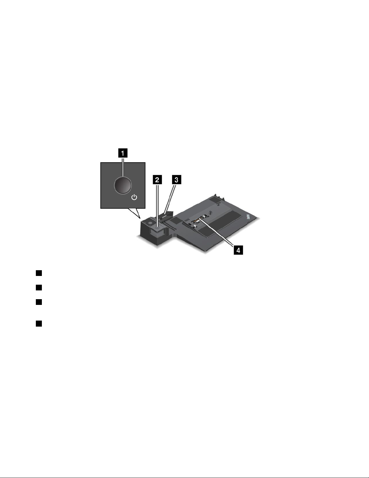
ThinkPadBattery19+topview
1ThedockingconnectorisusedforattachingtheThinkPadcomputertotheThinkPadBattery19+.
ThinkPadBattery19+bottomview
1ThepowerjackiswhereyouconnecttheACadapter.
2Bypressingtheindicatorbutton,thestatusindicatorshowstheThinkPadBattery19+chargestatus.
158UserGuide
Page 42

3ThestatusindicatoristoshowtheThinkPadBattery19+chargestatus.
4TheejectleveristoreleasetheThinkPadBattery19+fromthedockingconnectorinthecomputer.
5Thebatterylatchpreventstheejectleverfrombeingreleased.
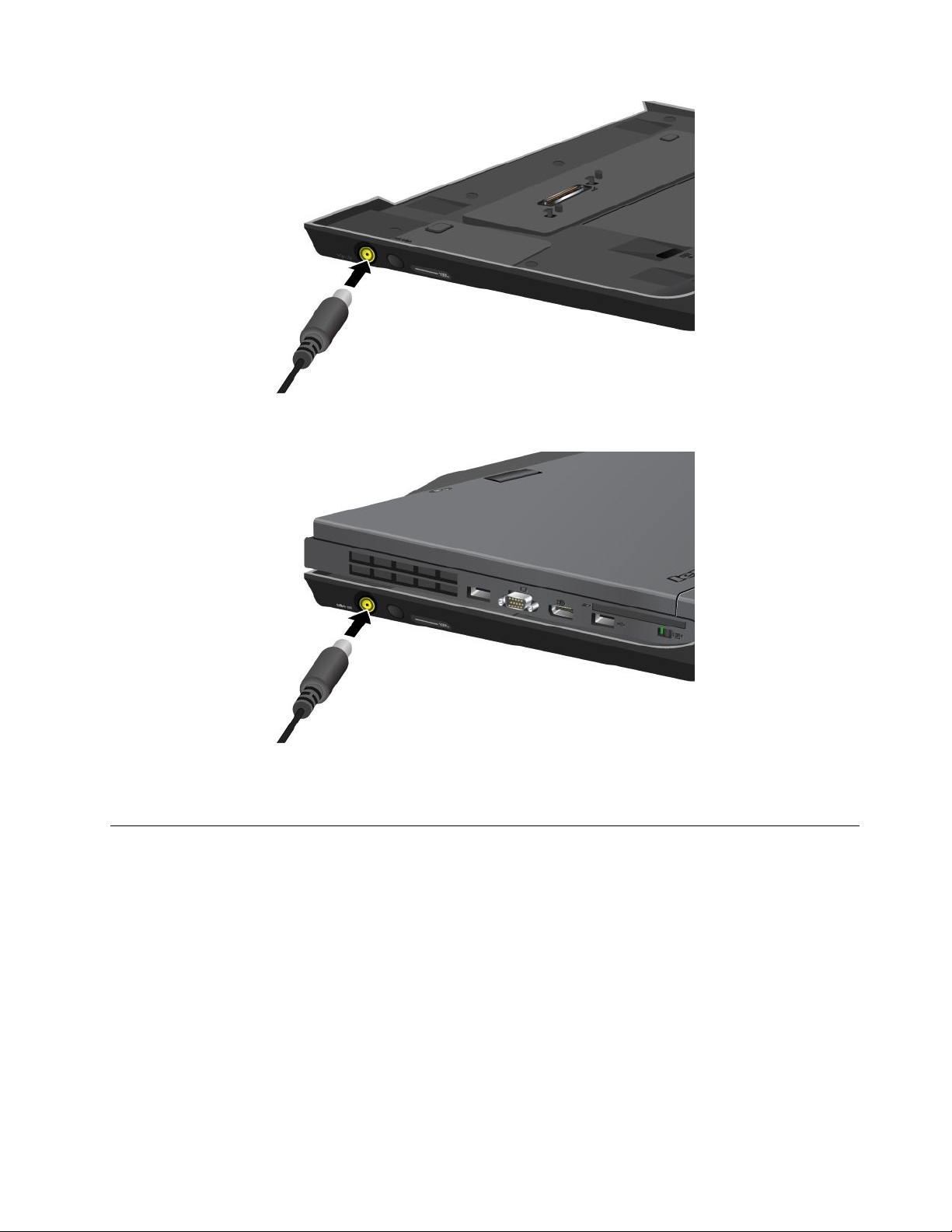
AttachingaThinkPadBattery19+
Attention:DisconnecttheACpowerfromyourcomputerbeforeyouattachtheThinkPadBattery19+.The
ACadapterconnectorwillbedamagedifitremainsconnectedtothecomputerduringtheattachment.
ToattachaThinkPadBattery19+,dothefollowing:
1.AlignthefrontofthecomputerwiththefrontoftheThinkPadBattery19+.
2.MakesurethattheguidesoftheThinkPadBattery19+alignwiththeholesofthecomputer1.Then
putthecomputerinplace2.
DetachingaThinkPadBattery19+
TodetachaThinkPadBattery19+,dothefollowing:
1.Unlockthebatterylatchbyslidingittotheunlockposition.
Chapter7.Enhancingyourcomputer159
Page 43

2.Releasetheejectlever2andpulluptheThinkPadBattery19+.
ChargingaThinkPadBattery19+
TheThinkPadBattery19+canbechargedseparately.
160UserGuide
Page 44
TheThinkPadBattery19+canalsobechargedwithacomputer.
WhentheThinkPadBattery19+ischargedwithacomputer,boththemainbatteryandThinkPadBattery
19+canbechargedsimultaneously.
ThinkPadPortReplicatorSeries3,ThinkPadMiniDockSeries3,and
ThinkPadMiniDockPlusSeries3
Note:OnlyThinkPadX220andX220isupportThinkPadPortReplicatorSeries3,ThinkPadMiniDock
Series3,andThinkPadMiniDockPlusSeries3.
AfteryouattachyourcomputertotheThinkPadPortReplicatorSeries3,theThinkPadMiniDockSeries3,or
theThinkPadMiniDockPlusSeries3,youcanuseitsconnectorsinplaceofthecomputer's.
WhenthecomputerisattachedtotheThinkPadPortReplicatorSeries3,theThinkPadMiniDockSeries
3,ortheThinkPadMiniDockPlusSeries3,neverpickuptheassemblybytakingholdofthecomputer
alone.Alwaysholdthewholeassembly.
FormoredetailsabouttheThinkPadPortReplicatorSeries3,theThinkPadMiniDockSeries3,orthe
ThinkPadMiniDockPlusSeries3,refertothefollowing:
Chapter7.Enhancingyourcomputer161
Page 45
•“Frontview”onpage162
•“Rearview”onpage165
•“AttachingaThinkPadPortReplicatorSeries3,ThinkPadMiniDockSeries3,orThinkPadMiniDock
PlusSeries3”onpage168
•“DetachingaThinkPadPortReplicatorSeries3,ThinkPadMiniDockSeries3,andThinkPadMiniDock
PlusSeries3”onpage170
•“Securityfeature”onpage172
•“Usingthesystemlockkey”onpage174
Frontview
ThinkPadPortReplicatorSeries3
1Thepowerswitchturnsthecomputeronandoff.
2TheejectbuttonreleasesthecomputerfromtheThinkPadPortReplicatorSeries3whenpressed.
3Theslidingadjusterisaguideusedtoalignthedockingconnectoronyourcomputerasyouattach
theThinkPadPortReplicatorSeries3.
4Thedockingconnectoriswhereyouattachyourcomputer.
162UserGuide
Page 46

ThinkPadMiniDockSeries3
1Thepowerswitchturnsthecomputeronandoff.
2Thekeylockindicatorlightswhenthesystemlockkeyisinthelockedposition.Whenthesystemlock
keyisinthelockedposition,theejectbuttonoftheThinkPadMiniDockSeries3islocked;youcannot
attachorremoveyourcomputer.
3Thedockingindicatorlightswhenyourcomputerisdocked.
4TheejectbuttonreleasesthecomputerfromtheThinkPadMiniDockSeries3whenpressed.
5Theslidingadjusterisaguideusedtoalignthedockingconnectoronyourcomputerasyouattachthe
ThinkPadMiniDockSeries3.
6Thedockingconnectoriswhereyouattachyourcomputer.
7Thesystemlockkeyisforlockingtheejectbutton.
Chapter7.Enhancingyourcomputer163
Page 47

ThinkPadMiniDockPlusSeries3
1Thepowerswitchturnsthecomputeronandoff.
2Thekeylockindicatorlightswhenthesystemlockkeyisinthelockedposition.Whenthesystem
lockkeyisinthelockedposition,theejectbuttonoftheThinkPadMiniDockPlusSeries3islocked;you
cannotattachorremoveyourcomputer.
3Thedockingindicatorlightswhenyourcomputerisdocked.
4TheejectbuttonreleasesthecomputerfromtheThinkPadMiniDockPlusSeries3whenpressed.
5Theslidingadjusterisaguideusedtoalignthedockingconnectoronyourcomputerasyouattach
theThinkPadMiniDockPlusSeries3.
6Thedockingconnectoriswhereyouattachyourcomputer.
7Thesystemlockkeyisforlockingtheejectbutton.
8Themicrophonejack,ajack1/8inch(3.5mm)indiameter,isforconnectinganexternalmicrophone.
9Theheadphonejack,ajack1/8inch(3.5mm)indiameter,isforconnectinganexternalstereoheadphone.
164UserGuide
Page 48

Rearview
ThinkPadPortReplicatorSeries3
1Thepowerjackisforconnectingtheacpoweradapter.
2TheEthernetconnectorisforconnectingtheThinkPadPortReplicatorSeries3toanEthernetLAN.
Theindicatorontheconnectoristhesameasthatonthecomputer.
Notes:
•YoucannotusetheTokenRingcableforthisconnector.
•Youcanusethisconnectorfora10BASE-T/100BASE-TX/1000BASE-TEthernet.
IfyouattachyourcomputertotheThinkPadPortReplicatorSeries3anduseanEthernetconnector,usethe
EthernetconnectorontheThinkPadPortReplicatorSeries3,nottheoneonthecomputer.
3TheUniversalSerialBusconnectorsareforconnectingUSB1.1andUSB2.0devices.
4Theexternalmonitorconnectorisforconnectinganexternalmonitor.
Note:IfyouattachyourcomputertotheThinkPadPortReplicatorSeries3anduseanexternalmonitor
connector,usetheexternalmonitorconnectorontheThinkPadPortReplicatorSeries3,nottheoneonthe
computer.
5Whenyouattachamechanicallocktothesecuritykeyhole,theejectbuttonislockedsothatthe
computercannotberemovedfromtheThinkPadPortReplicatorSeries3.
Chapter7.Enhancingyourcomputer165
Page 49

ThinkPadMiniDockSeries3
1Thepowerjackisforconnectingtheacpoweradapter.
2TheDisplayPortisforconnectingadisplaydevice.
3ThedigitalvisualinterfaceconnectorisforconnectingamonitorthatsupportsSingle-LinkDVI.
Note:TheDVIconnectorprovidesadigitalinterfaceonly.Thisconnectorcanbeusedwithacomputerthat
supportsDVIviadockingonly.
4Theheadphonejack,ajack1/8inch(3.5mm)indiameter,isforconnectinganexternalstereoheadphone.
5Themicrophonejack,ajack1/8inch(3.5mm)indiameter,isforconnectinganexternalmicrophone.
6TheEthernetconnectorisforconnectingtheThinkPadMiniDockSeries3toanEthernetLAN.The
indicatorontheconnectoristhesameasthatonthecomputer.
Notes:
•YoucannotusetheTokenRingcableforthisconnector.
•Youcanusethisconnectorfora10BASE-T/100BASE-TX/1000BASE-TEthernet.
IfyouattachyourcomputertotheThinkPadMiniDockSeries3anduseanEthernetconnector,usethe
EthernetconnectorontheThinkPadMiniDockSeries3,nottheoneonthecomputer.
7TheUniversalSerialBusconnectorsareforconnectingUSB1.1andUSB2.0devices.
8Theexternalmonitorconnectorisforconnectinganexternalmonitor.
Note:IfyouattachyourcomputertotheThinkPadMiniDockSeries3anduseanexternalmonitorconnector,
usetheexternalmonitorconnectorontheThinkPadMiniDockSeries3,nottheoneonthecomputer.
9Whenyouattachamechanicallocktothesecuritykeyhole,theejectbuttonislockedsothatthe
computercannotberemovedfromtheThinkPadMiniDockSeries3.
166UserGuide
Page 50

ThinkPadMiniDockPlusSeries3
1TheDisplayPortisforconnectingadisplaydevice.
2ThedigitalvisualinterfaceconnectorisforconnectingamonitorthatsupportsSingle-LinkDVI.
Note:TheDVIconnectorprovidesadigitalinterfaceonly.Thisconnectorcanbeusedwithacomputerthat
supportsDVIviadockingonly.
3TheDisplayPortisforconnectingadisplaydevice.
4ThedigitalvisualinterfaceconnectorisforconnectingamonitorthatsupportsSingle-LinkDVI.
Note:TheDVIconnectorprovidesadigitalinterfaceonly.Thisconnectorcanbeusedwithacomputerthat
supportsDVIviadockingonly.
5TheEthernetconnectorisforconnectingtheThinkPadMiniDockPlusSeries3toanEthernetLAN.
Theindicatorontheconnectoristhesameasthatonthecomputer.
Notes:
•YoucannotusetheTokenRingcableforthisconnector.
•Youcanusethisconnectorfora10BASE-T/100BASE-TX/1000BASE-TEthernet.
IfyouattachyourcomputertotheThinkPadMiniDockPlusSeries3anduseanEthernetconnector,usethe
EthernetconnectorontheThinkPadMiniDockPlusSeries3,nottheoneonthecomputer.
6TheUniversalSerialBusconnectorsareforconnectingUSB1.1andUSB2.0devices.
7Thepowerjackisforconnectingtheacpoweradapter.
8TheeSA T AisforconnectinganeSAT Adevice.
9Theexternalmonitorconnectorisforconnectinganexternalmonitor.
Note:IfyouattachyourcomputertotheThinkPadMiniDockPlusSeries3anduseanexternalmonitor
connector,usetheexternalmonitorconnectorontheThinkPadMiniDockPlusSeries3,nottheoneonthe
computer.
Chapter7.Enhancingyourcomputer167
Page 51

10Whenyouattachamechanicallocktothesecuritykeyhole,theejectbuttonislockedsothatthe
computercannotberemovedfromtheThinkPadMiniDockPlusSeries3.
AttachingaThinkPadPortReplicatorSeries3,ThinkPadMiniDock
Series3,orThinkPadMiniDockPlusSeries3
ToattachyourcomputertoaThinkPadPortReplicatorSeries3,aThinkPadMiniDockSeries3,ora
ThinkPadMiniDockPlusSeries3,dothefollowing:
ThefollowingdrawingsarefortheThinkPadMiniDockSeries3ortheThinkPadMiniDockPlusSeries3.
TheprocedureisthesamefortheThinkPadPortReplicatorSeries3.
Notes:
•BeforeyouattachthecomputertoaThinkPadPortReplicatorSeries3,aThinkPadMiniDockSeries3,or
aThinkPadMiniDockPlusSeries3,disconnectanacpoweradapterfromthecomputer.
•Ifyourcomputerisoperating,makesurethatithasnishedanyoperationsinvolvingdevicesthatare
connectedtoaUSBconnectorandaUSB/eSATAconnector.Alsomakesurethatanyconnectionto
anEthernetporthasended.
•BeforeyouattachyourcomputertoaThinkPadMiniDockSeries3,oraThinkPadMiniDockPlusSeries
3),makesurethatthesystemlockkeyisinplaceandintheunlocked(horizontal)position.
1.Toattachyourcomputer,makesurethatthesystemlockkeyisinplaceandintheunlocked(horizontal)
positionfortheThinkPadMiniDockSeries3,ortheThinkPadMiniDockPlusSeries3.Makesurethat
themechanicallockisdetachedfortheThinkPadPortReplicatorSeries3.
168UserGuide
Page 52

2.PressthebuttonoftheThinkPadMiniDockSeries3,ortheThinkPadMiniDockPlusSeries31.Pull
theslidingadjusterinthedirectionshownbythearrow2.
3.PutyourcomputerontheplatformoftheThinkPadMiniDockSeries3,ortheThinkPadMiniDockPlus
Series3,makingsurethatthetop-leftcornerofthecomputerisalignedtotheguideplateonthe
ThinkPadMiniDockSeries3,ortheThinkPadMiniDockPlusSeries3.
4.InsertyourcomputerintotheThinkPadMiniDockSeries3,ortheThinkPadMiniDockPlusSeries3,
alongthesurface,untilyouhearaclick.ThecomputerisnowattachedtotheThinkPadMiniDock
Series3,ortheThinkPadMiniDockPlusSeries3).
Note:IfthedockingindicatorisnotlightedafteryouattachtheThinkPadMiniDockSeries3,orthe
ThinkPadMiniDockPlusSeries3,yourcomputerisnotproperlyconnectedtothedock.Checkthe
acpoweradapterofthedock,ordisconnectandre-attachtheacpoweradapter.Thenattachyour
computertothedock.
Notes:
•IfyouattachtheThinkPadPortReplicatorSeries3,theThinkPadMiniDockSeries3,ortheThinkPadMini
DockPlusSeries3toyourcomputer,butdonotconnecttheacpoweradapterofthatattachmenttothe
powerjack,yourcomputergoesintobatterymode.
Chapter7.Enhancingyourcomputer169
Page 53
•IfyourcomputerandtheThinkPadPortReplicatorSeries3,theThinkPadMiniDockSeries3,orthe
ThinkPadMiniDockPlusSeries3areconnectedtoseparateacpoweradapters,yourcomputergoesinto
batterymoderst,andthenshiftsintoacmode.
•Ifineitherofthetwoprecedingsituationsthebatteryofyourcomputerisdetached,orhasnobattery
charge,yourcomputershutsdown.
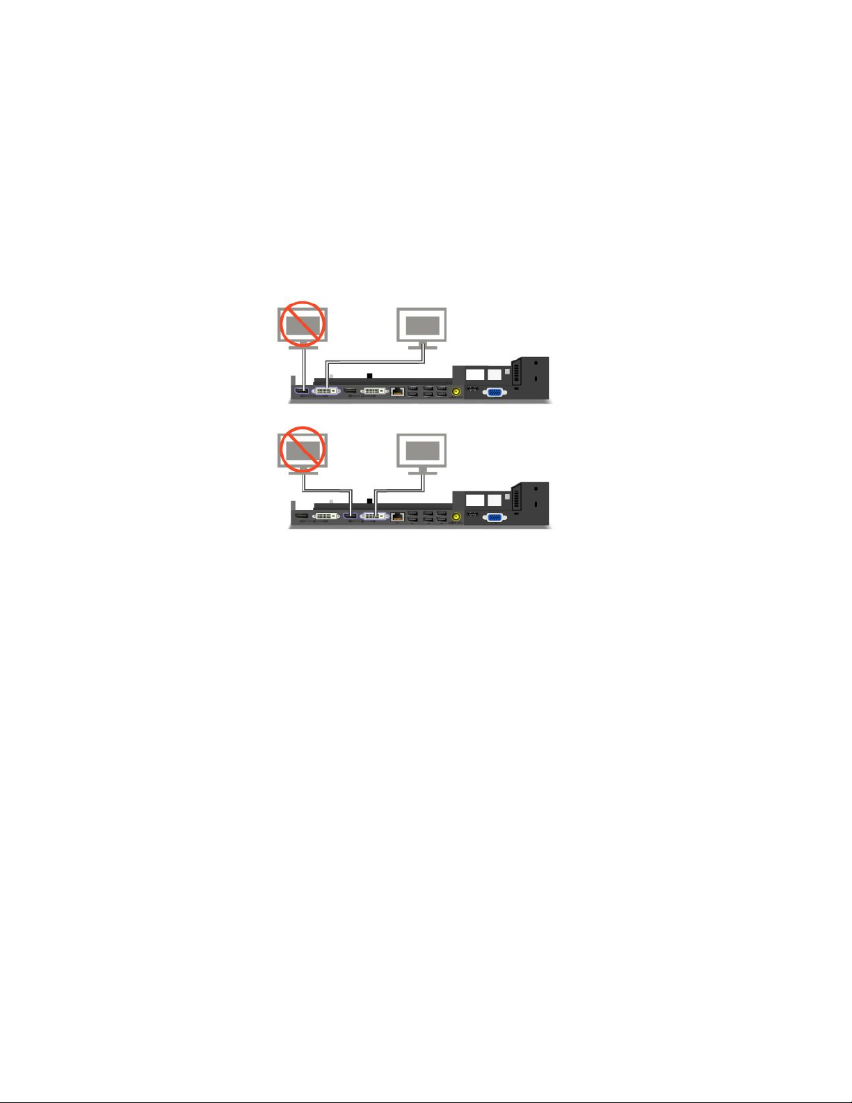
ConnectinganexternaldisplaytotheThinkPadMiniDockPlusSeries3
Group1(topgure)andGroup2(lowergure)areindependentofeachother.EachhasaDisplayPortanda
digitalvisualinterface.IfyouconnectadisplaytoaDisplayPortandaDVIthatareinthesamegroup,the
DisplayPortisinactive.
DetachingaThinkPadPortReplicatorSeries3,ThinkPadMiniDock
Series3,andThinkPadMiniDockPlusSeries3
TodetachyourcomputerfromtheThinkPadMiniDockSeries3,andtheThinkPadMiniDockPlusSeries3,
dothefollowing:
1.Makesurethat:
•ThedevicesconnectedtoUSBconnectorsarenotinuse.
•TheconnectiontoanEthernetporthasbeenended.
•ThedevicesconnectedtoaneSATAportarenotinuse(ThinkPadMiniDockPlusSeries3).
170UserGuide
Page 54

2.MakesurethatthesystemlockkeyoftheThinkPadMiniDockSeries3,ortheThinkPadMiniDock
PlusSeries3isinplaceandintheunlocked(horizontal)position.
3.Presstheejectbutton1untilthecomputermovesup;then,graspbothsides,andremovethe
computer2.
TodetachyourcomputerfromtheThinkPadPortReplicatorSeries3,dothefollowing:
Notes:
•Ifyourcomputerisoperating,makesurethatithasnishedoperationsinvolvingdevicesthatare
connectedtotheUSBconnector.AlsomakesurethatanyEthernetconnectionisstopped.
•Makesurethatthebatterypackisfullycharged.
1.MakesurethatallejectabledevicesconnectedtotheThinkPadPortReplicatorSeries3arestopped.
Chapter7.Enhancingyourcomputer171
Page 55

2.Presstheejectbutton1untilthecomputermovesup;then,graspbothsides,andremovethe
computer2.
Securityfeature
TheThinkPadPortReplicatorSeries3,theThinkPadMiniDockSeries3,ortheThinkPadMiniDockPlus
Series3hasasecuritykeyholeforamechanicallock.Byattachingamechanicallockwithcablethere,you
cansecuretheThinkPadPortReplicatorSeries3,theThinkPadMiniDockSeries3,ortheThinkPadMini
DockPlusSeries3toaheavyobject,suchasadesk.
IfyouusetheThinkPadPortReplicatorSeries3,andattachamechanicallock,theejectbuttonisalso
locked,sothatthecomputercannotbedetachedfromtheThinkPadPortReplicatorSeries3.
IfyouusetheThinkPadMiniDockSeries3ortheThinkPadMiniDockPlusSeries3,andattachamechanical
lock,theejectbuttonisnotlocked.Tolocktheejectbutton,usethesystemlockkey.
Lenovodoesnotofferamechanicallock.Y ouwillneedtopurchaseoneelsewhere.Y ouareresponsible
forevaluating,selecting,andimplementinganylockingdeviceandsecurityfeature.Lenovomakesno
comments,judgments,orwarrantiesaboutthefunction,quality,orperformanceofanylockingdeviceor
securityfeatures.
AttachamechanicallocktotheThinkPadMiniDockPlusSeries3asfollows:
172UserGuide
Page 56
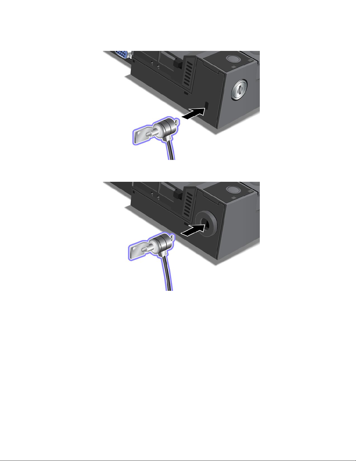
AttachamechanicallocktotheThinkPadMiniDockSeries3asfollows:
AttachamechanicallocktotheThinkPadPortReplicatorSeries3asfollows:
Chapter7.Enhancingyourcomputer173
Page 57

Usingthesystemlockkey
Thesystemlockkeyhastwopositions,unlockedandlocked.
Whenthekeyisinthelockedposition,theejectbuttonoftheThinkPadMiniDockSeries3ortheThinkPad
MiniDockPlusSeries3islocked,andyoucannotremoveyourcomputer.Thekeylockindicatorlights
whentheejectbuttonislocked.
174UserGuide
Page 58

Chapter8.Advancedconguration
Whileitisimportanttoprotectles,data,andsettingsthatareontheharddiskoronthesolidstatedrive,
youmayalsoneedtoinstallanewoperatingsystem,installnewdevicedrivers,updateyourUEFIBIOS,or
recoverpreinstalledsoftware.Thisinformationwillhelpyouhandleyourcomputerwithpropercareand
keepitintopworkingshape.
•“Installinganewoperatingsystem”onpage175
•“Installingdevicedrivers”onpage180
•“ThinkPadSetup”onpage183
•“Usingsystemmanagement”onpage199
Installinganewoperatingsystem
Ifyouinstallanewoperatingsysteminyourcomputer,youneedtoinstalltheSupplementlesandThinkPad
devicedriversforitatthesametime.Thenecessarylesarelocatedinthefollowingdirectoriesofyoursolid
statedriveorharddiskdrive:
•TheSupplementlesfortheoperatingsystemsupportedareintheC:\SWTOOLS\OSFIXESdirectory.
•ThedevicedriversfortheoperatingsystemsupportedareintheC:\SWTOOLS\DRIVERSdirectory.
•ThepreloadedsoftwareapplicationsareintheC:\SWTOOLS\APPSdirectory.
Notes:
•Theprocessofinstallingthenewoperatingsystemdeletesallthedataonyourharddisk,including
backupsorimagesthatwerestoredinahiddenfolderbyuseoftheRescueandRecoveryprogram.
•IfyoucannotndtheSupplementles,thedevicedrivers,andapplicationsoftwareyouneedonyour
harddiskdrive,orifyouwanttoreceiveupdatesandthelatestinformationaboutthem,goto:
http://www.lenovo.com/support/site.wss/document.do?sitestyle=lenovo&lndocid=tpad-matrix
Beforeyoubegin
Beforeyouinstalltheoperatingsystem,dothefollowing:
•CopyallthesubdirectoriesandlesintheC:\SWTOOL Sdirectorytoaremovablestoragedevice,toavoid
losinglesduringtheinstallation.
•Printthesectionsyouwillbeusing.Gotothesectionfortheoperatingsystemyouareusing:
–“Windows7”onpage176
–“WindowsVista”onpage177
–“WindowsXP”onpage178
Notes:IfyourcomputerisaWindowsVistaSP2orWindows7model,
–32-bitversionsofWindowsdonotsupportUEFIBIOSfeatures.Only64-bitversionsofWindowscan
takeadvantageofthefeaturesenabledby64-bitUEFIBIOS.
–IfyouwanttostartWindowsRecoveryEnvironment(WinRE)using64-bitversionofMicrosoftWindows
InstallationDVD,youshouldnotchangetheinitialUEFI/LegacyBootsettinginThinkPadSetup.The
UEFI/LegacyBootsettingmustbethesameasitwaswhentheWindowsOSimagewasinstalled.Or,
youwillseeanerror.
Forthecountryorregioncoderequiredintheinstallation,useoneofthefollowing:
©CopyrightLenovo2011
175
Page 59

Countryorregion:Code
China:SC
Denmark:DK
Finland:FI
France:FR
Germany:GR
Italy:IT
Japan:JP
Netherlands:NL
Netherlands:NL
Norway:NO
Spain:SP
Sweden:SV
TaiwanandHongKong:TC
UnitedStates:US
InstallingWindows7
Beforeyoustart,printtheseinstructions.
ToinstallWindows7anditsrelatedsoftwareonyourcomputer,doasfollows:
1.StarttheThinkPadSetup.
2.SelectStartupmenu.
3.SelectUEFI/LegacyBoot.
4.Dooneofthefollowing:
•IfyouwanttoinstalltheWindows732–bitoperatingsystem,selectLegacyOnlyorBoth.
•IfyouwanttoinstalltheWindows764–bitoperatingsysteminLegacymode,selectLegacyOnly.
•IfyouwanttoinstalltheWindows764–bitoperatingsysteminUEFImode,selectUEFIOnly.
5.PressF10.
6.ToinstallWindows7,inserttheDVDforWindows7intotheDVDdrive,andinstallWindows7fromthe
DVD.Thenrestartthecomputer,andfollowtheinstructionsonthescreen.
7.InstalltheIntelChipsetSupportforWindows2000/XP/Vista/7.Todothis,referto“InstallingIntel
ChipsetSupportforWindows2000/XP/Vista/7”onpage182
8.Installdevicedrivers.Todothis,referto“Installingdriversandsoftware”onpage183.
InstallingRegistryPatchesforWindows7
InstallthefollowingRegistryPatches:
•RegistrypatchenablingWakeUponLANfromStandbyforEnergyStar
•FixforIssueofHDDwithHDDetection
ToinstalltheseRegistryPatches,goto:
http://www.lenovo.com/support
InstallingtheWindows7UpdateModulePackage
TheWindows7UpdateModulesareinthefollowingdirectory:
C:\SWTOOLS\OSFIXES\.
.
Thenameofeachsubfolderisthenumberofaxmodule.Forinformationabouteachxmodule,goto
theMicrosoftKnowledgeBasehomepageathttp://support.microsoft.com/,typethenumberofthex
moduleyouneedinthesearcheld,andclickSearch.
176UserGuide
Page 60

Note:TheWebsiteaddressmightchangewithoutnotice.Ifthehomepageisnotdisplayed,searchforit
fromtheMicrosofttoppage.
Toinstallaxmodule,runtheEXEleinasubfolderandfollowtheinstructionsonthescreen.
Note:Ifyouremovetheharddiskdrivefromthecomputerwithasingle-coreprocessorandinstallitona
computerwithadual-coreprocessor,youcangetaccesstotheharddiskdrive.Theopposite,however,is
nottrue:Ifyouremovetheharddiskdrivefromacomputerwithadual-coreprocessorandinstallitona
computerwithasingle-coreprocessor,youcannotgetaccesstotheharddiskdrive.
InstallingWindowsVista
Beforeyoustart,printtheseinstructions.
Note:Y ourcomputersupportsWindowsVistawiththeServicePack2.BeforeyouinstallWindowsVista
ServicePack2,makesureyouinstalltheWindowsVistaServicePack1rst.
ToinstallWindowsVistaanditsrelatedsoftwareonyourcomputer,doasfollows:
1.StarttheThinkPadSetup.
2.SelectStartupmenu.
3.SelectUEFI/LegacyBoot.
4.Dooneofthefollowing:
•IfyouwanttoinstalltheWindowsVista32–bitoperatingsystem,selectLegacyOnlyorBoth.
•IfyouwanttoinstalltheWindowsVista64–bitoperatingsysteminLegacymode,selectLegacyOnly.
•IfyouwanttoinstalltheWindowsVista64–bitoperatingsysteminUEFImode,selectUEFIOnly.
5.PressF10.
6.InserttheDVDforWindowsVistaintegratedwithServicePack1intotheDVDdrive,andrestartthe
computer.
7.CompletetheinstallationofWindowsVistaServicePack1byfollowingOSinstallinginstructions.
8.InstalltheWindowsVistaServicePack2.Y oucaninstalltheWindowsVistaServicePack2usingthe
WindowsVistaServicePack2InstallationCDordownloaditfromeitherMicrosoftDownloadCenteror
MicrosoftWindowsupdateWebsite.
9.InstalltheIntelChipsetSupportforWindows2000/XP/Vista/7.Todothis,referto“InstallingIntel
ChipsetSupportforWindows2000/XP/Vista/7”onpage182
10.Installdevicedrivers.Todothis,referto“Installingdriversandsoftware”onpage183.
.
InstallingRegistryPatchesforWindowsVista
InstallthefollowingRegistryPatches:
•RegistryPatchenablingDeviceInitiatedPowerManagementonSATA
•RegistryPatchenablingUSBS3PowerManagement
•RegistrypatchtochangeIDLEIRPtimingbyFingerprintreader
•RegistrypatchenablingWakeUponLANfromStandbyforEnergyStar
•RegistrypatchtoimproveUSBdevicedetectiononresumefromsleep
•FixforIssueofHDDwithHDDetection
ToinstalltheseRegistryPatches,goto:
http://www.lenovo.com/support
Chapter8.Advancedconguration177
Page 61

InstallingtheWindowsVistaUpdateModulePackage
TheWindowsVistaUpdateModulesareinthefollowingdirectory:
C:\SWTOOLS\OSFIXES\.
Thenameofeachsubfolderisthenumberofaxmodule.Forinformationabouteachxmodule,goto
theMicrosoftKnowledgeBasehomepageathttp://support.microsoft.com/,typethenumberofthex
moduleyouneedinthesearcheld,andclickSearch.
Note:TheWebsiteaddressmightchangewithoutnotice.Ifthehomepageisnotdisplayed,searchforit
fromtheMicrosofttoppage.
Toinstallaxmodule,runthe.exeleinasubfolderandfollowtheinstructionsonthescreen.
Note:Ifyouremovetheharddiskdrivefromthecomputerwithasingle-coreprocessorandinstallitona
computerwithadual-coreprocessor,youcangetaccesstotheharddiskdrive.Theopposite,however,is
nottrue:Ifyouremovetheharddiskdrivefromacomputerwithadual-coreprocessorandinstallitona
computerwithasingle-coreprocessor,youcannotgetaccesstotheharddiskdrive.
InstallingWindowsXP
Beforeyoustart,printtheseinstructions.
Note:OnlyThinkPadX220andThinkPadX220isupportWindowsXP.
Note:YourcomputersupportsWindowsXPwithServicePack3.BeforeyouinstalltheWindowsXPService
Pack3,makesureyouinstalltheWindowsXPServicePack2rst.
YoumustinstallIntelRapidStorageTechnologyDriverbeforeinstallingtheoperatingsystem.Toinstallit,you
mayneedtoattachadiskettedrivetoyourcomputer.Ifyouhaveadiskettedrive,followtheprocedurebelow.
Beforeinstallingtheoperatingsystem,installIntelRapidStorageT echnologyDriverasfollows:
Note:BesuretoinstallIntelRapidStorageTechnologyDriverbeforeinstallingtheoperatingsystem.
Otherwiseyourcomputerwillnotrespond;itwillonlydisplayabluescreen.
1.Attachadiskettedrivetoyourcomputer.
2.CopyIntelRapidStorageT echnologyDriverfromC:\SWTOOLS\DRIVERS\IMSMtoadiskette.
3.TomakesurethatSATAAHCIisenabled,starttheThinkPadSetup.
4.SelectCong.
5.SelectSerialA TA(SA T A).
6.SelectAHCI.
7.Changethestartupsequenceofyourcomputer.SelectStartupmenu.
8.SelectUEFI/LegacyBoot.
9.SelectBothorLegacyOnly.
10.PressF10.
11.InserttheCDforWindowsXPintegratedwithServicePack2intotheCDorDVDdrive,andrestartthe
computer.
12.Toinstallathird-partySCSIdriverrst,pressF6.
13.Whenprompted,selectSforSpecifyAdditionalDevice.
14.Whenprompted,insertthediskettethatyoucreatedinstep2,andpressEnter.
15.Scrollthelistofdrivers.IftheSAT AsettingofyoucomputerissettoAHCI,selectIntel
ExpressChipsetSA TAAHCIController.
®
Mobile
178UserGuide
Page 62

16.Tocontinuetheinstallation,pressEnteragain.Leavethedisketteinthedriveuntilthenextreboot;the
softwaremayneedtobecopiedfromthedisketteagainwhenthelesarecopiedduringsetup.
17.CompletetheinstallationofWindowsXPServicePack2byfollowingOSinstallinginstructions.
18.InstallWindowsXPServicePack3.Y oucaninstalltheWindowsXPServicePack3usingtheWindows
XPServicePack3InstallationCDordownloaditfromeitherMicrosoftDownloadCenterorMicrosoft
WindowsupdateWebsite.
19.InstalltheIntelChipsetSupportforWindows2000/XP/Vista/7.Todothis,referto“InstallingIntel
ChipsetSupportforWindows2000/XP/Vista/7”onpage182.
20.ApplythePCMCIAPowerPolicyRegistryPatch.Todothis,gotoC:\SWTOOLS\OSFIXES\PCMCIAPW\,
double-clickinstall.bat.Thenfollowtheinstructionsthatappearonthescreen.
21.Installdevicedrivers.Todothis,referto“Installingdriversandsoftware”onpage183.
Ifyoudonothaveadiskettedrive,youcaninstallIntelRapidStorageTechnologyDriverbythefollowing
alternativeprocedure:
Note:IfyouselectAHCIforSerialATA(SATA)intheThinkPadSetupbeforeinstallingIntelRapidStorage
TechnologyDriver,yourcomputerwillnotrespond;itwillonlydisplayabluescreen.
1.StarttheThinkPadSetup.
2.SelectCong.
3.SelectSerialA TA(SA T A).
4.SelectCompatibility.
5.Changethestartupsequenceofyourcomputer.SelectStartupmenu.
6.SelectUEFI/LegacyBoot.
7.SelectLegacyOnlyorBoth.
8.PressF10.
9.InserttheinstallationCDforWindowsXPintegratedwithServicePack2intotheCDorDVDdrive,and
restartthecomputer.
10.CompletetheinstallationofWindowsXPServicePack2byfollowingOSinstallinginstructions.
11.InstallWindowsXPServicePack3.Y oucaninstalltheWindowsXPServicePack3usingtheWindows
XPServicePack3InstallationCDordownloaditfromeitherMicrosoftDownloadCenterorMicrosoft
WindowsupdateWebsite.
12.RunIntelRapidStorageTechnologyDriver.Todothis,gotoC:\DRIVERS\WIN\IRST\PREPARE,and
double-clickinstall.cmd.
13.Turnthecomputeroffandthenonagain.
14.StarttheThinkPadSetup.
15.SelectCong.
16.SelectSerialA TA(SA T A).
17.SelectAHCI.
18.StartWindowsXP .TheWelcometotheFoundNewHardwareWizardappears.
19.SelectNo,notthistime,andthenclickNext.
20.SelectInstallfromalistorspeciclocation(Advanced),andthenclickNext.
21.SelectSearchforthebestdriverintheselocations.ThenselectIncludethislocationinthesearch:,
specifythepath,C:\DRIVERS\WIN\IRST,andclickNext.TheCompletingtheFoundNewHardware
Wizardappears.
22.ClickFinish.
Chapter8.Advancedconguration179
Page 63

23.WhentheSystemSettingsChangewindowappears,clickY es.Thecomputerrestarts.
24.InstalltheIntelChipsetSupportforWindows2000/XP/Vista/7.Todothis,referto“InstallingIntel
ChipsetSupportforWindows2000/XP/Vista/7”onpage182.
25.ApplythePCMCIAPowerPolicyRegistryPatch.Todothis,gotoC:\SWTOOLS\OSFIXES\PCMCIAPW\,
double-clickinstall.bat,andthenfollowtheinstructionsthatappearonthescreen.
26.Installdevicedrivers.Todothis,referto“Installingdriversandsoftware”onpage183.
Installingdevicedrivers
Toinstalldevicedrivers,refertothewebsite:
http://www.lenovo.com/support
Installingthedriverforthe4-in-1MediaCardReader
Tousethe4-in-1MediaCardReader,youneedtodownloadandinstalltheRicohMultiCardReaderDriver
forWindowsXP/Vistax86/x64.Todownloadit,gotoLenovoWebsiteat:
http://www.lenovo.com/support/site.wss/document.do?sitestyle=lenovo&lndocid=tpad-matrix
Note:IfyouareinstallingWindowsXPanew,besuretoinstallRICOHSD/MMCBusHost
AdapterdriverforWindows2000/XP77sp05wwrst.Todownloadit,visitLenovoWebsite
athttp://www.lenovo.com/support/site.wss/document.do?sitestyle=lenovo&lndocid=tpad-matrix,andthen
installthedriver.
Toinstallthedriver,doasfollows:
1.ClickStart➙AllPrograms➙Accessories➙CommandPrompt.TheDOSpromptwindowappears.
2.TypeStandardInstall.batattheDOSprompt.TheWelcometotheDeviceDriverInstallationWizardfor
theRICOHMediaDriveropens.
3.ClickNext.Ifthedevicedriverisalreadyinstalled,clickNo.Otherwise,followtheinstructionson
thescreen.
InstallingthedriverforUSB3.0
IfyourcomputersupportsUSB3.0,andyouhavereinstalledtheoperatingsystem,youneedtodownload
andinstalltheUSB3.0drivertousetheUSB3.0.Dothefollowing:
ForWindows7andWindowsVista
1.AccessLenovoWebsiteat
http://www.lenovo.com/support/site.wss/document.do?sitestyle=lenovo&lndocid=HOME-LENOVO
Whenyougettothesite,ndyourmodelanddisplaythedriverlinks.
2.SelecttheUSB3.0driverfor32-bitor64-bitandextractittoyourlocalharddisk.
3.Double-clickSetup.exeinC:\DRIVERS\WIN\USB3.0\.
4.ClickNext.Ifthedevicedriverisalreadyinstalled,clickCancel.Followtheinstructionsonthescreen
untiltheinstallationisnished.
ForWindowsXP
1.AccessLenovoWebsiteat
http://www.lenovo.com/support/site.wss/document.do?sitestyle=lenovo&lndocid=HOME-LENOVO.
Whenyougettothesite,ndyourmodelanddisplaythedriverlinks.
2.SelecttheUSB3.0driverfor32-bitandextractittoyourlocalharddisk.
3.Double-clickSetup.exeinC:\DRIVERS\WIN\USB3.0\.
180UserGuide
Page 64

4.ClickNext.Ifthedevicedriverisalreadyinstalled,clickCancel.Followtheinstructionsonthescreen
untiltheinstallationisnished.
InstallingThinkPadMonitorFileforWindows2000/XP/Vista/7
ThinkPadMonitorFileforWindows2000/XP/Vista/7isinthefollowingdirectory:
C:\SWTOOLS\DRIVERS\MONITOR.
Note:Ifyoucannotndthisdirectoryonyourharddiskdriveorsolidstatedrive,downloadtheThinkPad
MonitorFileforWindows2000/XP/Vista/7fromtheThinkPadWebsiteat:
http://www.lenovo.com/support/site.wss/document.do?sitestyle=lenovo&lndocid=tpad-matrix
Note:Beforeyouinstallthisle,makesurethatthecorrectvideodriverhasbeeninstalled.
ForWindows7
1.Right-clickonthedesktop,andclickPersonalize.
2.ClickDisplayattheleft.
3.ClickChangedisplaysettings.
4.ClickAdvancedSettings.
5.ClicktheMonitortab.
6.ClickProperties.
7.ClicktheDrivertab.
8.ClickUpdateDriver.
9.SelectBrowsemycomputerfordriversoftware,andthenclickLetmepickfromalistofdevice
driversonmycomputer.
10.ClickHaveDisk.
11.Specifypath“C:\SWTOOLS\DRIVERS\MONITOR”tothismonitorINFthenclickOpen.
12.ClickOK.
13.Conrmthecorrectdisplaytype,thenclickNext.
14.Windowshasnishedinstalling.ClickClose.
15.ClickCloseforDisplayProperties.
16.ClickOKintheMonitortab.
17.ClickOKandclosetheDisplaySettingswindow.
ForWindowsVista
1.Right-clickonthedesktop,andclickPersonalize.
2.ClickDisplaySettings.TheDisplaySettingswindowopens.
3.ClickAdvancedSettings.
4.ClicktheMonitortab.
5.ClickProperties.(ForWindowsVista,alsoclickContinue.)
6.ClicktheDrivertab.
7.ClickUpdateDriver.
8.SelectBrowsemycomputerfordriversoftware,andthenclickLetmepickfromalistofdevice
driversonmycomputer.
9.ClickHaveDisk.
10.Specifypath“C:\SWTOOLS\DRIVERS\MONITOR”tothismonitorINFthenclickOpen.
Chapter8.Advancedconguration181
Page 65

11.ClickOK.
12.Conrmthecorrectdisplaytype,thenclickNext.
13.Windowshasnishedinstalling.ClickClose.
14.ClickCloseforDisplayProperties.
15.ClickOKintheMonitortab.
16.ClickOKandclosetheDisplaySettingswindow.
ForWindowsXP
1.Right-clickonthedesktopandselectPropertiesfromthepop-upmenu.
2.SelecttheSettingstab.
3.ClicktheAdvancedtab.
4.SelecttheMonitortab.
5.SelectPlugandPlayMonitorfromthemonitortypelist.
6.ClickProperties.
7.SelecttheDrivertabandclickUpdateDriver.TheHardwareUpdateWizardstarts.
8.SelectNo,notthistimeforWindowsUpdateconnection,andthenclickNext.
9.SelectInstallfromalistorspeciclocation(Advanced).
10.ClickNext.
11.SelectDon'tsearch,Iwillchoosethedrivertoinstall.
12.ClickNext.
13.ClickHaveDisk.
14.ClickBrowse.
15.Specify“C:\SWTOOLS\DRIVERS\MONITOR”aslocationdirectoryandselectTPLCD.INF .
16.ClickOK.
17.SystemwillshowThinkPadDisplay.ClickNext.SystemwillcopyThinkPadMonitorINFleandcolor
prole.
18.ClickFinishandthenClose.
19.ClicktheColorManagementtab.
20.ClickAdd.
21.SelectTPFLX.ICMorTPLCD.ICMandclickAdd.
22.ClickOKandclosetheDisplayPropertieswindow.
InstallingIntelChipsetSupportforWindows2000/XP/Vista/7
Beforeyoubegin
Beforeyouinstalltheoperatingsystem,CopyallthesubdirectoriesandlesintheC:\SWTOOLSdirectorytoa
removablestoragedevice,toavoidlosinglesduringtheinstallation.
ToinstallIntelChipsetSupportforWindows2000/XP/Vista/7,dothefollowing:
1.RestoreC:\SWTOOLSfromthebackupcopyyoumadebeforestartingtheinstallation.
2.Runinnst_autol.exeinC:\SWTOOLS\DRIVERS\INTELINF.
182UserGuide
Page 66

Installingdriversandsoftware
ThedevicedriversareprovidedintheC:\SWTOOLS\DRIVERSdirectoryonyourharddiskdrive.Y ouwillalso
needtoinstallapplicationsoftware,whichisprovidedintheC:\SWTOOLS\APPSdirectoryonyourharddisk
drive.Todothis,refertotheinstructionsin“Reinstallingpreinstalledapplicationsanddevicedrivers”on
page114
Note:IfyoucannotndtheSupplementles,devicedrivers,andapplicationsoftwareyouneedonyour
harddiskdrive,orifyouwanttoreceiveupdatesandthelatestinformationaboutthem,refertotheThinkPad
Websiteat:
http://www.lenovo.com/support/site.wss/document.do?sitestyle=lenovo&lndocid=tpad-matrix
.
ThinkPadSetup
Yourcomputerprovidesaprogram,calledThinkPadSetup,thatenablesyoutoselectvarioussetup
parameters.
TostartThinkPadSetup,doasfollows:
1.Toprotectyourselfagainstaccidentallossofdata,backupyourcomputerregistry.See“Performing
backupandrecoveryoperations”onpage111.
2.Ifthediskettedriveisconnectedtothecomputer,removeanydiskettefromthediskettedrive,and
thenturnoffthecomputer.
3.Turnonthecomputer.Whenthelogoscreenisdisplayed,presstheF1key.TheThinkPadSetupopens.
Ifyouhavesetasupervisorpassword,theThinkPadSetupmenuappearsafteryouenterthepassword.
YoucanstarttheThinkPadSetupbypressingEnterinsteadofenteringthesupervisorpassword;
however,youcannotchangetheparametersthatareprotectedbythesupervisorpassword.Formore
information,referto“UsingPasswords”onpage91
AnexampleoftheThinkPadSetupmenuisshownasbelow:
.
Chapter8.Advancedconguration183
Page 67

4.Usingthecursorkeys,movetoanitemyouwanttochange.Whentheitemyouwantishighlighted,
pressEnter.Asubmenuisdisplayed.
5.Changetheitemsyouwishtochange.Tochangethevalueofanitem,press+/-.Iftheitemhasa
submenu,youcandisplayitbypressingEnter.
6.PressEsctoexitfromthesubmenu.
7.Ifyouareinanestedsubmenu,pressEscrepeatedlyuntilyoureachtheThinkPadSetupmenu.
Note:Ifyouneedtorestorethesettingstotheiroriginalstateasofthetimeofpurchase,pressF9to
loadthedefaultsettings.Y oucanalsoselectanoptionintheRestartsubmenutoloadthedefault
settingsordiscardthechanges.
8.SelectRestart.Movethecursortotheoptionyouwantforrestartingyourcomputer;thenpressEnter.
Yourcomputerrestarts.
Congmenu
Ifyouneedtochangethecongurationofyourcomputer,selectCongfromtheThinkPadSetupmenu.
Notes:
•Thedefaultsettingsarealreadyoptimizedforyou.Ifyouconsiderchangingthecomputerconguration,
proceedwithextremecaution.Settingthecongurationincorrectlymightcauseunexpectedresults.
•Ineachsubmenu,presstheEnterkeytoshowselectableoptionsandselectadesiredoptionbyusing
cursorkey,ortypedesiredvaluesfromthekeyboarddirectly.
Thefollowingsubmenuisdisplayed:
•Network:SettheLANrelatedfunctions.
•USB:EnableordisableUSBrelatedfunctions.
•Keyboard/Mouse:Setthekeyboardandthemouserelatedfunctions.
•Display:Specifythesettingsfordisplayoutput.
•Power:Setpowermanagementrelatedfunctions.
•BeepandAlarm:Enableordisabletheaudiorelatedfunctions.
•SerialATA(SAT A):Specifythesettingsfortheharddiskdrive.
•CPU:SpecifythesettingsfortheCPU.
•IntelAMT:SettheIntel
®
AMTrelatedfunctions.
Dateandtimemenu
Ifyouneedtosetthecurrentdateandtimeofyourcomputer,selectDate/TimefromtheThinkPadSetup
menu.Thefollowingsubmenuisdisplayed:
•SystemDate
•SystemTime
Tochangethedateandtime,dothefollowing:
1.Usingtheupanddownarrowkeys,selecttheitemtochange-dateortime.
2.PressT ab,ShiftTab,orEntertoselectaeld.
3.Typethedateortime.
Note:Anotherwaytoadjustdateandtimeispressthe-or+key.
184UserGuide
Page 68

Securitymenu
Ifyouneedtosetthesecurityfeaturesofyourcomputer,selectSecurityfromtheThinkPadSetupmenu.
Notes:
•Thedefaultsettingsarealreadyoptimizedforyou.Ifyouconsiderchangingthecomputerconguration,
proceedwithextremecaution.Settingthecongurationincorrectlymightcauseunexpectedresults.
•Ineachsubmenu,youcanenableafunctionbyselectingEnabled,ordisableitbyselectingDisabled.
Thefollowingsubmenuisdisplayed:
•Password:Setapasswordrelatedfunctions.
•Fingerprint:Setthengerprintreaderrelatedfunctions.
•SecurityChip:Setthesecuritychiprelatedfunctions.
•UEFIBIOSUpdateOption:SpecifythesettingsforFlashUEFIBIOSupdate.
•MemoryProtection:SpecifythesettingsfortheDataExecutionPreventionfeature.
•Virtualization:EnableordisablethesettingsforIntelVirtualizationT echnologyandIntelVT-dFeature.
•I/OPortAccess:EnableordisabletheaccesstoindividualI/Oports.
•Anti-Theft:EnableordisableUEFIBIOSinterfacetoactivateAnti-Theftservices,suchasIntelATand
Computrace.
Tosetapasswordrelatedfunctions,gototheSecuritymenuandselectPassword.Thefollowingsubmenu
isdisplayed:
•HardwarePasswordManager
•SupervisorPassword
•LockUEFIBIOSSettings
•SetMinimumLength
•Passwordatunattendedboot
•Passwordatrestart
•Power-OnPassword
•HardDiskxPassword
Notes:
•HardDisk1meanstheharddiskdrivebuiltintoyourcomputer.
•HardDisk2appearsonthePasswordsubmenuonlyifaharddiskdriveisinstalledintheserialUltrabay
enhanced.
IfyouselectandenableHardwarePasswordManager,youcanmanageyourpower-onpassword,
supervisorpassword,andyourharddiskpasswordsbythemanagementserver.Bydefault,thisisset
toEnabled.
LockUEFIBIOSSettingsenableordisablethefunctionthatprotectsitemsintheThinkPadSetupfrom
beingchangedbyauserwhodoesnothavethesupervisorpassword.Bydefault,thisissettoDisabled.
Ifyousetthesupervisorpasswordandenablethisfunction,noonebutyoucanchangeanyitemsinthe
ThinkPadSetup.
IfyouselectSetMinimumLength,youcanspecifyaminimumlengthforpower-onpasswordsandhard
diskpasswords.Bydefault,thisissettoDisabled.Ifyousetthesupervisorpasswordandspecifya
minimumlengthforpasswords,noonebutyoucanchangethelength.
Chapter8.Advancedconguration185
Page 69

IfyouselectandenablePasswordatunattendedboot,apasswordpromptisdisplayedwhenthecomputer
isturnedon,fromeitherapower-offstateorhibernation,byanunattendedeventsuchasWakeonLAN
youselectDisabled,nopasswordpromptisdisplayed;thecomputergoesaheadandloadstheoperating
system.T opreventunauthorizedaccess,settheuserauthenticationontheoperatingsystem.
IfyouselectandenablePasswordatrestart,apasswordpromptisdisplayedwhenyourestartthe
computer.IfyouselectDisabled,nopasswordpromptisdisplayed;thecomputergoesaheadandloadsthe
operatingsystem.T opreventunauthorizedaccess,settheuserauthenticationontheoperatingsystem.
Startupmenu
Youmayneedtochangethestartupsequenceofyourcomputer.Forexample,ifyouhavedifferentoperating
systemsondifferentdevices,youcanhavethesystemstartupfromeitherofthem.
Attention:Afteryouchangeyourstartupsequence,youmustbeextremelycarefulnottospecifyawrong
deviceduringacopy,asave,oraformatoperation.Ifyouspecifyawrongdevice,yourdataandprograms
mightbeerasedoroverwritten.
Attention:IfyouareusingtheBitLockerdriveencryption,youshouldnotchangethestartupsequence.
BitLockerdriveencryptiondetectsthechangeofstartupsequenceandlocksthecomputerfrombooting.
Changingthestartupsequence
SelectingtheStartuptodisplaytheBootsubmenu.
Tochangethestartupsequence,dothefollowing:
1.SelectBoot;thenpressEnter.
®
.If
•YoucanusetheBootsubmenutospecifythestartupsequencethatrunswhenyouturnonthe
power.Referto“Bootsubmenu”onpage186
•YoucanusetheNetworkBoottospecifythetopprioritybootdevicethatrunswhenWakeon
LANiscommonlyusedbyLANadministratorsincorporatenetworkstogetremoteaccesstoyour
computer.Referto“NetworkBoot”onpage187
2.Selectthedeviceyouwanttostartrst.
UsethesekeystosettheorderthattheUEFIBIOSwillusewhenstartinganoperatingsystem:
•+or-keymovesthedeviceupordown.
3.PressF10tosavethechangesandrestartthesystem.
Tochangethestartupsequencetemporarilysothatthesystemstartsupfromadifferentdrive,dothe
following:
1.Turnoffthecomputer.
2.Turnonthecomputer;then,whilethe“Tointerruptnormalstartup,presstheblueThinkVantagebutton”
messageisdisplayedatthelower-leftofthescreen,pressF12.
3.SelectthedeviceyouwanttostartrstfromtheBootmenu.
Note:TheBootmenuisalsoshownwhenthesystemcannotbootfromanydevicesoroperating
systemwasnotfound.
Bootsubmenu
Thefollowinglist,showingtheorderinwhichdeviceswillbestartedup,isalwaysdisplayed.Evendevices
thatarenotattachedtoorinstalledonyourcomputerarelisted.Foreachdevicethatisattachedtoor
installedonthecomputer,informationaboutitispresentedafterthecolon.
1.USBCD:
.
.
186UserGuide
Page 70

2.USBFDD:
3.ATAPICD0:
4.ATAHDD0:
5.ATAHDD1:
6.ATAHDD2:
7.USBHDD:
8.PCILAN:
9.ATAPICD1:
10.ATAPICD2:
11.ATAHDD3:
12.ATAHDD4:
13.OtherCD:
14.OtherHDD:
NetworkBoot
UsetheNetworkBoottoselectthebootdevicewhenthesystemwakesfromLAN.IfWake-on-LANis
enabled,thenetworkadministratorcanturnonallofthecomputersinaLANremotelybyuseofnetwork
managementsoftware.
OtheritemsintheStartupmenu
ThefollowingitemsarealsodisplayedintheStartupmenuoftheThinkPadSetup:
•UEFI/LegacyBoot:Selectsystembootcapability.
•UEFI/LegacyBootPriority:SelectpriorityofbootoptionbetweenUEFIandLegacy.
•BootMode:Enableordisablethediagnosticsbootmode.
•OptionKeyDisplay:Choosewhethertoshowtheoptionkeymessagewhenthesystemisbooted.
•BootdeviceListF12Option:Choosewhethertoshowthepop-uplistofthebootdevices.
•BootOrderLock:EnableordisabletheBootPriorityOrderlock.
Restartmenu
IfyouneedtoclosetheThinkPadSetupandrestartthesystem,selectRestartfromtheThinkPadSetup
menu.Thefollowingsubmenuisdisplayed:
•ExitSavingChanges:Restartthesystemaftersavingthechanges.
•ExitDiscardingChanges:Restartthesystemwithoutsavingthechanges.
•LoadSetupDefaults:Loadthedefaultsettingthatwasineffectatthetimeofpurchase.
•DiscardChanges:Discardthechanges.
•SaveChanges:Savethechanges.
ThinkPadSetupitems
Thefollowingtablesshowthecontentsofthe“Congmenuitems”onpage188,the“Securitymenuitems”
onpage194,andthe“Startupmenu”onpage198oftheThinkPadSetup.
Note:Someitemsaredisplayedonthemenuonlyifthecomputersupportsthecorrespondingfeatures.
Notes:
Chapter8.Advancedconguration187
Page 71

•Enabledmeansthatthefunctioniscongured.
•Disabledmeansthatthefunctionisnotcongured.
•Defaultvaluesareinboldface.
Congmenuitems
Table6.Congmenuitems
Menuitem
Network
USB
SubmenuitemSelectionComments
WakeOnLAN
EthernetLANOptionROM
USBUEFIBIOSSupport
AlwaysOnUSB
•Disabled
•AConly
•ACandBattery
•Disabled
•Enabled
•Disabled
•Enabled
•Disabled
•Enabled
EnablethesystemtoPower
onwhentheEthernet
controllerreceivesamagic
packet.
Ifyouselect“ACOnly”,
WakeOnLANisenabled
onlywhenacpoweradapter
isattached.
Ifyouselect“ACand
Battery”,WakeOnLANis
enabledwithanypower
sources.
Note:ACisrequiredwith
magicpackettypeWake
OnLAN.
Note:WakeOnLAN
functiondoesnotwork
whenaharddiskpassword
isset.
LoadtheEthernetLAN
OptionROMtoenable
startupfromanintegrated
networkdevice.
Enableordisableboot
supportforUSBdiskette,
USBmemorykey,andUSB
opticaldrive.
Ifyouselect“Enabled”,the
externalUSBdevicescan
bechargedviaUSBports
evenwhenthesystemisin
lowpowermode(standby,
hibernate,orpower-off).
188UserGuide
Page 72

Table6.Congmenuitems(continued)
Menuitem
Keyboard/Mouse
SubmenuitemSelectionComments
AlwaysOnUSBChargein
offmode
•Disabled
•Enabled
TrackPoint•Disabled
•Enabled
Ifyouselect“Enabled”,the
AlwaysOnUSBconnector
enablesyoutocharge
somedevices,suchasiPod
andiPhoneandBlackBerry
smartphones.
Note:Ifyouwanttocharge
thesedeviceswhenyour
computerisinhibernation
modeorpoweredoff,you
willneedtoopenthePower
Managerprogramand
congurecorresponding
settingstoenablethe
AlwaysOnUSBconnector
function.Fordetails
abouthowtoenablethe
AlwaysOnUSBconnector
function,refertotheonline
helpofthePowerManager
program.
Enableordisablethe
built-inTrackPoint.
TouchPad•Disabled
FnandCtrlKeyswap
Note:Ifyouwanttouse
anexternalmouse,select
“Disabled.”
Enableordisablethe
•Enabled
built-intouchpad.
Note:Ifyouwanttouse
anexternalmouse,select
“Disabled.”
•Disabled
•Enabled
Ifyouselect“Enabled”,the
FnkeyworksastheCtrl
key,andtheCtrlkeyworks
astheFnkey.
Note:Evenwhen
“Enabled”isselected,
youneedtopresstheFn
keytoreturnthecomputer
fromsleepmodetonormal
operation.
Chapter8.Advancedconguration189
Page 73

Table6.Congmenuitems(continued)
Menuitem
SubmenuitemSelectionComments
FnKeyLock•Disabled
•Enabled
ThinkPadNumLock•Independent
•Synchronized
Power-OnNumLock
•Automatic
•On
•Off
Ifyouselect“Enabled”,
youcanpresstheFnkey
tokeepitinapressed
condition,andthenpress
thedesiredfunctionkey.
Theactionisequivalentto
pressingtherequired
keyandtheFnkey
simultaneously.Ifyou
presstheFnkeytwice,the
stateislockeduntilyou
presstheFnkeyagain.
Ifyouselect“Independent”,
NumLockonyour
computercanbedisabled
independentlyregardless
oftheNumLockstateof
theexternalkeyboard.If
NumLockonthecomputer
isenabled,NumLockon
theexternalkeyboardwill
alsobeenabled.
Ifyouselect
“Synchronized”,NumLock
onyourcomputerand
NumLockontheexternal
keyboardaresynchronized.
Ifyouselect“Automatic”,
NumLockisenabled
whenfullsizekeyboardis
attached.
190UserGuide
Ifyouselect“On”,
NumLockisalways
enabled.
Ifyouselect“Off”,
NumLockisalways
disabled.
Note:Power-OnNumLock
willbedisplayedifyou
select“Synchronized”at
theThinkPadNumLock.
Page 74

Table6.Congmenuitems(continued)
Menuitem
Display
SubmenuitemSelectionComments
BootDisplayDevice
•ThinkPadLCD
•Analog(VGA)
•DigitalonThinkPad
•Digital1ondock
•Digital2ondock
GraphicsDevice•IntegratedGraphics
•DiscreteGraphics
•NVIDIAOptimus
Selectthedisplaydevice
thatistobeactiveatboot
time.Thisselectionis
effectiveforboottime,
passwordprompt,and
ThinkPadSetup.
“DigitalonThinkpad”
isDisplayPortonyour
computer.
“Digial1ondock”and
“Digital2ondock”are
DisplayPortorDVIon
dockingstation.
IntegratedGraphicswill
achievelongerbatterylife,
andDiscreteGraphics
enhancesperformance.
NVIDIAOptimusrunsas
IntegratedGraphicsmode
andDiscreteGraphicsis
enabledondemand.
Note:NVIDIAOptimus
modeshouldonlybe
selectedifyouareusinga
Windows7model.
OSDetectionforNVIDIA
Optimus
•Disabled
•Enabled
SystemBIOSautomatically
switchesGraphicsdevice
settingtoNVIDIAOptimus
modeiftheOSsupports
thefeature,andtoDiscrete
GraphicsiftheOSdoesnot
supportit.
Power
IntelSpeedStep
®
technology(Intel
SpeedStepmounted
modelsonly)
•Disabled
•Enabled
ModeforAC
•MaximumPerformance
•BatteryOptimized
ModeforBattery
•MaximumPerformance
•BatteryOptimized
SelectthemodeofIntel
SpeedSteptechnologyat
runtime.
MaximumPerformance:
Alwayshighestspeed
BatteryOptimized:Always
lowestspeed
Disabled:Noruntime
support,lowestspeed
Chapter8.Advancedconguration191
Page 75

Table6.Congmenuitems(continued)
Menuitem
SubmenuitemSelectionComments
AdaptiveThermal
Management
OpticalDriveSpeed
CPUPowerManagement
PCIExpressPower
Management
PowerOnwithACAttach
SchemeforAC
•MaximizePerformance
•Balanced
SchemeforBattery
•MaximizePerformance
•Balanced
•HighPerformance
•Normal
•Silent
•Disabled
•Enabled
•Disabled
•Enabled
•Disabled
•Enabled
Thisselectsathermal
managementschemeto
use.
MaximizePerformance:
ReducesCPUthrottling
Balanced:Balances
sound,temperatureand
performance
Note:Eachschemeaffects
fansound,temperature,
andperformance.
Setthespeedofoptical
drivetothedesired
performance.
Enableordisablethepower
savingfeaturethatstop
themicroprocessorclock
automaticallywhenthere
arenosystemactivities.
Normally,itisnotnecessary
tochangethesetting.
Enableordisableafeature
thatautomaticallyadjusts
powermanagementwhen
thereisnoPCIExpress
activity.Normally,itisnot
necessarytochangethe
setting.
Enableordisableafeature
thatpowersonthesystem
whenACisattached.
192UserGuide
Ifyouselect“Enabled”,the
systemispoweredonwhen
ACisattached.Whenthe
systemisinhibernatestate,
thesystemresumes.
Ifyouselect“Disabled”,the
systemisnotpoweredon
norresumedwhenACis
attached.
Page 76

Table6.Congmenuitems(continued)
Menuitem
BeepandAlarm
SubmenuitemSelectionComments
PowerControlBeep
LowBatteryAlarm•Disabled
PasswordBeep•Disabled
KeyboardBeep•Enabled
SerialA T A(SATA)SATAControllerMode
Option
CPU
CoreMulti-Processing
•Disabled
•Enabled
Ifthisfunctionisenabled,
abeepsoundswhenthe
computerentersapower
managementmode,whenit
resumesoperationalmode,
andwhentheacpower
adapterisconnectedor
disconnected.
Enableordisablethelow
•Enabled
batteryalarm.
Enablethisoptiontohave
•Enabled
abeepsoundwhenthe
systemiswaitingfora
power-on,harddisk,or
supervisorpassword.
Differentbeepswillbe
soundedwhentheentered
passwordmatchesordoes
notmatchthecongured
password.
Enableordisablekeyboard
•Disabled
beepwhenunmanageable
keycombinationsare
pressed.
•Compatibility
•AHCI
•RAID
SelectSATAcontroller
operationmode.Ifyour
systemsupportsRAID,
select“RAID. ”Ifyouselect
“Compatibilitymode”,
serialSATAcontroller
operatesincompatibility
mode.
•Disabled
•Enabled
Enableordisableadditional
executioncoreunitswithin
aCPU.
IntelHyper- Threading
Technology
Note:Ifyouareusinga
computerwithasingle-core
processor,thisitemdoes
notappear.
Note:ForCore
Multi-Processing,refer
totheinstructionsin
“InstallingWindowsXP”on
page178
•Disabled
•Enabled
Chapter8.Advancedconguration193
Enableordisableadditional
logicalprocessorswithina
processorcore.
.
Page 77

Table6.Congmenuitems(continued)
Menuitem
IntelAMT
SubmenuitemSelectionComments
IntelAMTControl
CIRATimeout
•Disabled
•Enabled
0-255
Ifyouselect“Enabled”,Intel
AMT(ActiveManagement
Technology)iscongured
andadditionalsetupitems
areprovidedinMEBx
(ManagementEngineBIOS
Extension)Setup.
Note:YoucanenterMEBx
Setupmenubypressing
Ctrl-Pkeycombinationin
StartupInterruptMenu.T o
displaytheStartupInterrupt
Menu,pressThinkVantage
buttonorEnterkeyduring
POST.
Settimeoutoptionfor
CIRAconnectiontobe
established.1though254
secondsareselectable.
Ifyouselect“0”,use60
secondsasdefaulttimeout
value.
Securitymenuitems
Table7.Securitymenuitems
Menuitem
Password
Fingerprint
ConsoleType•PC-ANSI
•VT100+
•VT-UTF8
SubmenuitemSelectionComments
PredesktopAuthentication•Disabled
•Enabled
ReaderPriority•External➙Internal
•InternalOnly
Ifyouselect“255”,waiting
timeforestablishinga
connectionisunlimited.
Selecttheconsoletypefor
AMT.
Note:Thisconsoletype
shouldmatchtheIntelAMT
remoteconsole.
Referto“Securitymenu”
onpage185and“Using
passwords”onpage91.
Enableordisablengerprint
authenticationbeforethe
operatingsystemisloaded.
IfExternal➙Internal
isselected,anexternal
ngerprintreaderisused
ifattached.Otherwise,an
internalngerprintreader
isused.IfInternalOnly
isselected,aninternal
ngerprintreaderisused.
194UserGuide
Page 78

Table7.Securitymenuitems(continued)
Menuitem
SecurityChip
SubmenuitemSelectionComments
SecurityMode
•Normal
•High
Ifngerprintauthentication
fails,youcanstillstart
thecomputerbyentering
apassword.Ifyouhave
selected“Normal”,entera
power-onpasswordora
supervisorpassword;ifyou
haveselected“High”,enter
asupervisorpassword.
PasswordAuthentication•Disabled
•Enabled
Enableordisablepassword
authentication.Ifhigh
securitymodeisselected,
thisitemappears.
ResetFingerprintData•EnterThisoptionisusedtoerase
allngerprintdatastored
inthengerprintreader
andresetsettingstothe
factorystate(ex.Power-on
security,LEDs,etc.)As
aresult,anypower-on
securityfeaturespreviously
enabledwillnotbeable
toworkuntiltheyare
re-enabledinthengerprint
software.
SecurityChip
•Active
•Inactive
•Disabled
Ifyouselect“Active”,
SecurityChipisfunctional.
Ifyouselect“Inactive”,
SecurityChipisvisible,but
isnotfunctional.Ifyou
select“Disabled”,Security
Chipishiddenandisnot
functional.
SecurityReportingOptions
Enableordisablethe
followingSecurity
ReportingOptions.
•BIOSROMString
Reporting:BIOStext
string
•ESCDReporting:
Extendedsystem
congurationdata
•CMOSReporting:
CMOSdata
•NVRAMReporting:
Securitydatastoredin
theAssetID
•SMBIOSReporting:
SMBIOSdata
Chapter8.Advancedconguration195
Page 79

Table7.Securitymenuitems(continued)
Menuitem
UEFIBIOSUpdateOption
MemoryProtectionExecutionPrevention•Disabled
Virtualization
SubmenuitemSelectionComments
ClearSecurityChip
IntelTXTFeature•Disabled
FlashBIOSUpdatingby
End-Users
FlashOverLAN
IntelVirtualization
Technology
IntelVT-dFeature•Disabled
•Enter
•Enabled
•Disabled
•Enabled
•Disabled
•Enabled
•Enabled
•Disabled
•Enabled
•Enabled
Cleartheencryptionkey.
Note:Onlyifyouselect
“Active”forSecurityChip,
thisitemappears.
EnableordisableIntel
TrustedExecution
Technology.
Ifyouselect“Enabled”,
alluserscanupdatethe
UEFIBIOS.Ifyouselect
“Disabled”,onlytheperson
whoknowssupervisor
passwordcanupdatethe
UEFIBIOS.
Enableyourcomputer's
UEFIBIOStobeupdated
(ashed)overanactive
networkconnection.
Somecomputerviruses
andwormscausememory
bufferstooverowby
runningcodewhereonly
dataisallowed.Ifthe
DataExecutionPrevention
featurecanbeusedwith
youroperatingsystem,then
byselecting“Enabled”you
canprotectyourcomputer
againstattacksbysuch
virusesandworms.Ifafter
choosing“Enabled”you
ndthatanapplication
programdoesnotrun
correctly,select“Disabled”
andresetthesetting.
Ifyouselect“Enabled,”
aVMM(VirtualMachine
Monitor)canutilizethe
additionalhardware
capabilitiesprovided
byIntelVirtualization
Technology.
IntelVT-disIntel
VirtualizationTechnology
forDirectedI/O.When
enabled,aVMMcanutilize
theplatforminfrastructure
forI/Ovirtualization.
196UserGuide
Page 80

Table7.Securitymenuitems(continued)
Menuitem
I/OPortAccess
SubmenuitemSelectionComments
EthernetLAN•Disabled
•Enabled
WirelessLAN•Disabled
•Enabled
WiMAX•Disabled
•Enabled
WirelessWAN•Disabled
•Enabled
Bluetooth•Disabled
•Enabled
Modem•Disabled
•Enabled
USBPort
•Disabled
•Enabled
IEEE1394•Disabled
•Enabled
ExpressCardSlot
•Disabled
•Enabled
Ultrabay(HDD/Optical)
•Disabled
•Enabled
eSATAPort
•Disabled
•Enabled
MemoryCardSlot
•Disabled
•Enabled
IntegratedCamera
•Disabled
•Enabled
Microphone•Disabled
•Enabled
FingerprintReader•Disabled
•Enabled
Ifyouselect“Enabled”,you
canusetheEthernetLAN
device.
Ifyouselect“Enabled”,you
canusetheWirelessLAN
device.
Ifyouselect“Enabled”,you
canusetheWiMAXdevice.
Ifyouselect“Enabled”,you
canusetheWirelessWAN
device.
Ifyouselect“Enabled”,
youcanusetheBluetooth
device.
Ifyouselect“Enabled”,you
canusetheModemdevice.
Ifyouselect“Enabled”,you
canusetheUSBport.
Ifyouselect“Enabled”,
youcanusetheIEEE1394
(Firewire)device.
Ifyouselect“Enabled”,you
canusetheExpressCard
Slot.
Ifyouselect“Enabled”,
youcanusetheUltrabay
(HDD/Optical)device.
Ifyouselect“Enabled”,you
canusetheeSATAPort.
Ifyouselect“Enabled”,
youcanusethe
MemoryCardslot(SD
Card/MultiMediaCard).
Ifyouselect“Enabled”,
youcanusetheIntegrated
Camera.
Ifyouselect“Enabled”,you
canusetheMicrophone
(Internal,External,or
Line-In).
Ifyouselect“Enabled”,
youcanusethengerprint
reader.
Chapter8.Advancedconguration197
Page 81

Table7.Securitymenuitems(continued)
Menuitem
Anti-Theft
SubmenuitemSelectionComments
IntelA TModuleActivation•Disabled
•Enabled
•PermanentlyDisabled
ComputraceModule
Activation
•Disabled
•Enabled
•PermanentlyDisabled
EnableordisabletheUEFI
BIOSinterfacetoactivate
IntelATmodulethatisan
optionalAnti-Theftservice
fromIntel.
Note:IfyousettheIntel
ATmoduleactivationto
“PermanentlyDisabled”,
youwillbeunabletoenable
thissettingagain.
EnableordisabletheUEFI
BIOSinterfacetoactivate
Computracemodule.
Computraceisanoptional
monitoringservicefrom
AbsoluteSoftware.
Note:Ifyousetthe
Computracemodule
activationto“Permanently
Disabled”,youwillbe
unabletoenablethis
settingagain.
Startupmenuitems
Table8.Startupmenuitems
Menuitem
Boot
NetworkBoot
UEFI/LegacyBoot
UEFI/LegacyBootPriority
SelectionComments
•Both
•UEFIOnly
•LegacyOnly
•UEFIFirst
•LegacyFirst
Referto“Startupmenu”onpage186.
Referto“Startupmenu”onpage186.
Selectsystembootcapability.
•Both:Systemwillbootby
followingUEFI/LegacyBoot
Prioritysetting.
•UEFIOnly:Systemwillbootfrom
UEFIenabledOS.
•LegacyOnly:Systemwillboot
fromanyOSotherthanUEFI
enabledOS.
Note:Ifyouselect“UEFIOnly”,
systemcannotbootfromthe
bootabledeviceswhichdonothave
UEFIenabledOS.
Selectpriorityofbootoptionbetween
UEFIandLegacy.
198UserGuide
Page 82

Table8.Startupmenuitems(continued)
Menuitem
BootMode
OptionKeysdisplay(ThinkVantage
buttonmessage)
BootDeviceListF12Option
BootOrderLock
SelectionComments
•Quick
•Diagnostics
Note:Youcanalsoenterthe
“Diagnostic”modebypressingEsc
duringPOST.
•Disabled
•Enabled
•Disabled
•Enabled
•Disabled
•Enabled
ScreenduringPOST:
•Quick:ThinkPadLogoscreenis
displayed.
•Diagnostics:Textmessagesare
displayed.
Ifyouselect“Disabled”,the“T o
interruptnormalstartup,pressthe
blueThinkVantagebutton.”message
isnotdisplayedduringPOST.
Ifyouselect“Enabled”,theF12key
isrecognizedandtheBootMenuis
displayed.
Ifyouselect“Enabled”,theBoot
PriorityOrderislockedforyourfuture
use.
UpdatingyoursystemUEFIBIOS
TheUniedExtensibleFirmwareInterface(UEFI)BIOSisapartofthesystemprogramsthatmakeupthe
basiclayerofsoftwarebuiltintoyourcomputer.UEFIBIOStranslatestheinstructionsfromothersoftware
layers.
Yourcomputersystemboardhasamodulecalledelectricallyerasableprogrammableread-onlymemory
(EEPROM,alsoreferredtoasashmemory).YoucanupdateUEFIBIOSandtheConguration/ThinkPad
SetupProgrambystartingyourcomputerwithaashupdateopticaldiscor.ashupdatetoolapplication
runningontheWindwosenvironment.
Insomeinstanceswhenyouaddsoftware,hardware,oradevicedriver,youmaybeinformedthatyouneed
toupdateyourUEFIBIOSinorderforthenewadditiontoworkproperly.
ToupdateyourUEFIBIOS,visitthisWebsiteat
http://www.lenovo.com/support/site.wss/document.do?sitestyle=lenovo&lndocid=tpad-matrix
Thenfollowtheinstructionsonthescreen.
Usingsystemmanagement
Thissectionisintendedprimarilyfornetworkadministrators.
Yourcomputerisdesignedformanageability,sothatyoucanredirectmoreofyourresourcestobetter
meetyourbusinessobjectives.
Thismanageability,or“TotalCostofOwnership”(TCO),enablesyoutoremotelypoweronyourcomputer,
formattheharddiskdrive,installthesoftwareofyourchoice(forexample,WindowsXPwithuserand
system-managementapplications),andhavethecomputerstartupandfunctioninthesamewayasan
ordinarydesktopPC.
Oncethecomputerisconguredandoperational,youcanmanageitbyuseofsoftwareandmanageability
featuresalreadyintegratedintotheclientsystemandthenetwork.
Chapter8.Advancedconguration199
Page 83

Systemmanagement
CheckthefollowingtopicstolearnmoreaboutfeaturesofSystemManagement:
•DesktopManagementInterface
•PrebooteXecutionEnvironment
•WakeonLAN
•Resumeonincomingcall
•AssetIDEEPROM
DesktopManagementInterface
ThesystemBIOS(UEFIBIOS)ofyourcomputersupportsaninterfacecalledSystemManagementBIOS
ReferenceSpecication(SMBIOS)V2.6.1.SMBIOSprovidesinformationaboutthehardwarecomponents
ofyoursystem.ItistheresponsibilityoftheBIOStosupplythisdatabasewithinformationaboutitself
andthedevicesonthesystemboard.Thisspecicationdocumentsthestandardsforgettingaccessto
thisBIOSinformation.
PrebooteXecutionEnvironment
PrebooteXecutionEnvironment(PXE)technologymakesyourcomputermoremanageable(itisPXE
2.1-compliant)byenablingittoboot(loadanoperatingsystemoranotherexecutableimage)fromaserver.
YourcomputersupportsthePCfunctionsthatPXErequires.Forexample,withtheappropriateLANcard,
yourcomputercanbebootedfromthePXEserver.
Note:RemoteProgramLoad(RPL)cannotbeusedwithyourcomputer.
WakeonLAN
AnetworkadministratorcanuseWakeonLANtoturnonacomputerfromamanagementconsole.
WhenWakeonLANisusedwithnetworkmanagementsoftware,manyfunctions,suchasdatatransfer,
softwareupdates,andFlashBIOSupdates,canbeperformedremotelywithoutremoteattendance.This
updatingcanbedoneafternormalworkinghoursandonweekends,tosavetimeandincreaseproductivity.
Usersarenotinterruptedduringnormalworkinghours,andLANtrafciskepttoaminimum.
IfacomputeristurnedonbytheWakeonLANfunction,theNetworkbootsequenceisused.
Resumeonincomingcall
IfyourcomputerisconnectedtoatelephonelineandyouhavespeciedResumeonincomingcall,itwill
returnfromsleep(standby)modetonormaloperationwhenatelephonecallcomesin.
Toenableyourcomputertowakeupfromsleep(standby)mode,dothefollowing:
ForWindows7andWindowsVista:
1.ClickStart,andthenclickControlPanel.
2.ClickHardwareandSound.
3.ClickDeviceManager.Ifyouarepromptedforanadministratorpasswordorconrmation,typethe
passwordorprovideconrmation.TheDeviceManagerwindowopens.
4.Double-clickModems(inWindowsVista,clickthe+markforModems),andthenclickyourmodem.
5.ClickthePowerManagementtab.
6.SelecttheAllowthisdevicetowakethecomputercheckbox.
ForWindowsXP:
200UserGuide
Page 84

1.ClickStart,andthenclickControlPanel.
2.ClickPerformanceandMaintenance.
3.ClickSystem.
4.ClicktheHardwaretab.
5.ClicktheDeviceManagerbutton.TheDeviceManagerwindowopens.
6.Clickthe+markforModems,andthenclickyourmodem.
7.ClickAction,andthenclickProperties.
8.ClickthePowerManagementtab.
9.SelecttheAllowthisdevicetobringthecomputeroutofStandbycheckbox.
AssetIDEEPROM
TheAssetIDEEPROMcontainsinformationaboutthesystem,includingitscongurationandtheserial
numbersofkeycomponents.Italsoincludesanumberofblankeldsinwhichyoucanrecordinformation
abouttheendusersinyournetwork.
Settingmanagementfeatures
Toenablethenetworkadministratortocontrolyourcomputerremotely,youmustcongurethenetwork
interfacebysettingthesystem-managementfeaturesintheThinkPadSetup.ThatThinkPadSetupcontains
thefollowingfunctions:
•WakeonLAN
•Networkbootsequence
•Flashupdate
Ifanadministrator'spassword(supervisorpassword)hasbeenset,youwillneedtospecifyitwhenyoustart
theThinkPadSetup,sothatyoucanusethesefunctions.
WakeonLAN
WhentheWakeonLANfeatureisenabledonacomputerthatisconnectedtoaLAN,anetworkadministrator
canstartthecomputerremotelyfromamanagementconsole,usingremotenetwork-managementsoftware.
SettingupintheThinkPadSetup
ToenableordisableWakeonLAN,gototheThinkPadSetupmenu.Whenyourcomputerisnotunderthe
networkadministrator'ssystemmanagement,youcandisableWakeonLAN.
Tosetthisfunction,dothefollowing:
1.StarttheThinkPadSetupmenu.
2.SelectCong.
3.TheCongsubmenuappears.
4.SelectNetwork.
5.TheNetworkitemsubmenuappears.
6.ForWakeOnLAN,selectoneofthefollowing:ACOnly,ACandBattery,orDisabled.
7.PressF10.
NetworkBootsequence
Whenyourcomputeristurnedonremotely,systemwilltrytobootfromthedevicethatisselectedby
NetworkBootsetting,andthenfollowthebootorderlistintheBootmenu.
Chapter8.Advancedconguration201
Page 85

Todeneasequence:
1.OntheThinkPadSetupmenu,selectStartup.TheStartupsubmenuappears.
2.SelectNetworkBootandpressEnterkeytoshowpop-upbootdevicelist.
3.Selectabootdevicefromthelisttomakeitastopbootpriority.
4.PressF10.
Note:Ifyouwanttoinitializethesettingtoreturntothedefaultstartupsequence,pressF9.Thedefault
settingsareautomaticallyreloaded.
Flashupdate
WhenaFlashUEFIBIOSupdatefromthenetworkisenabled,anetworkadministratorcanremotely
updatethesystemprogramsinyourcomputerfromamanagementconsole.Thefollowingrequirements
mustbemet:
•UpdateFlashfromnetworkmustalsobeenabled;theprocedureisgivenbelow.
•YourcomputermustbestartedovertheLAN.
•YourcomputermustbeengagedinaPrebooteXecutionEnvironment.
•Network-managementsoftwaremustbeinstalledintheremoteadministrator'scomputer.
ToenableordisabletheFlashupdatefromthenetworksetting,dothefollowing:
1.OntheThinkPadSetupmenu,selectSecurity.TheSecuritysubmenuappears.
2.SelectUEFIBIOSUpdateOption.TheUEFIBIOSUpdateOptionsubmenuappears.
3.ForFlashOverLAN,selecteitherEnabledorDisabled.
4.PressF10.
202UserGuide
Page 86

Chapter9.Preventingproblems
AnimportantpartofowningaThinkPadnotebookismaintenance.Withpropercare,youcanavoid
commonproblems.Thefollowingsectionsprovideinformationthatcanhelpyoutokeepyourcomputer
runningsmoothly.
•“Generaltipsforpreventingproblems”onpage203
•“Makingsuredevicedriversarecurrent”onpage204
•“Takingcareofyourcomputer”onpage205
Generaltipsforpreventingproblems
1.Checkthecapacityofyourharddiskdrivefromtimetotime.Iftheharddiskdrivegetstoofull,Windows
willslowdownandmightproduceerrors.
Note:InWindows7andWindowsVista,clickStart➙Computer.InWindowsXP,clickStart➙
MyComputer.
2.Emptyyourrecyclebinonaregularbasis.
3.Usediskdefragmenttoolregularlyonyourharddiskdrivetoimprovedataseekandreadtimes.
4.Tofreeupdiskspace,uninstallunusedapplicationprograms.
Note:Youmightalsowanttolookforapplicationprogramduplicationoroverlappingversions.
5.CleanoutyourInbox,Sent,andTrashfoldersfromyoure-mailclientprogram.
6.Atleastonceaweek,makeapointtobackupyourdata.Ifcriticaldataispresent,itisagoodidea
toperformadailybackup.Lenovohasmanybackupoptionsavailableforyourcomputer.Rewritable
opticaldrivesareavailableformostmachinesandareeasilyinstalled.
7.UseorscheduleSystemRestoretotakeasystemsnapshotperiodically.Formoreinformationabout
SystemRestoreseeChapter5“Recoveryoverview”onpage109.
8.UpdatedevicedriversandUEFIBIOSwhenneeded.
9.Proleyourmachineathttp://www.lenovo.com/think/supporttokeepuptodatewithcurrentdrivers
andrevisions.
10.Keepuptodatefordevicedriversonothernon-Lenovohardware.Youmightwanttoreadthedevice
driverinformationreleasenotespriortoupdatingforcompatibilityorknownissues.
11.Keepalogbook.Entriesmightincludemajorhardwareorsoftwarechanges,driverupdates,minor
issuesyouhaveexperiencedandhowyouresolvedthem.
12.Ifyoueverneedtorunarecoveryonyourcomputertoreturnthepreloadontothemachine,the
followingtipsmighthelpalongtheway:
•Removeallexternaldevicessuchastheprinter,keyboard,etc.
•Makesurethatyourbatteryischargedandthatyouhavetheacpowerconnected.
•BootintotheThinkPadSetupandloadthedefaultsettings.
•Restartthemachineandstarttherecovery.
•Ifyourmachineusesdiscsastherecoverymedia,DONOTremovethediscfromthedriveuntil
promptedtodoso.
13.Forsuspectedharddiskdriveissues,referto“Diagnosingproblems”onpage209andrunLenovo
ThinkVantageT oolboxforadiagnostictestofthedrivepriortocallingtheCustomerSupportCenter.
Ifyourcomputerdoesnotstartup,downloadthelestocreateabootableself-testmediafromthe
followingWebsite:http://www.lenovo.com/hddtest.Runthetestandrecordanymessagesorerror
codes.Ifthetestreturnsanyfailingerrorcodesormessages,calltheCustomerSupportCenterwiththe
codesormessagesandthecomputerinfrontofyou.Atechnicianwillassistyoufurther.
©CopyrightLenovo2011
203
Page 87

14.Ifrequired,youcanndyourcountry'sCustomerSupportCenteratthefollowingWebaddress:
http://www.lenovo.com/support/site.wss/document.do?sitestyle=lenovo&lndocid=migr-4hwse3.When
callingtheCustomerSupportCenter,pleasemakesureyouhaveyourmachinemodeltype,serial
numberandthecomputerinfrontofyou.Also,ifthemachineisproducingerrorcodes,itishelpfulto
havetheerrorscreenonorthemessagewrittendown.
Makingsuredevicedriversarecurrent
Devicedriversareprogramsthatcontaininstructionsfortheoperatingsystemabouthowtooperateor
“drive”acertainpieceofhardware.Eachhardwarecomponentonyourcomputerhasitsownspecicdriver.
Ifyouaddanewcomponent,theoperatingsystemneedstobeinstructedonhowtooperatethatpiece
ofhardware.Afteryouinstallthedriver,theoperatingsystemcanrecognizethehardwarecomponent
andunderstandhowtouseit.
Note:Becausedriversareprograms,likeanyotherleonyourcomputer,theyaresusceptibletocorruption
andmightnotperformproperlyifcorruptionoccurs.
Itisnotalwaysnecessarytodownloadthelatestdrivers.However,youshoulddownloadthelatestdriver
foracomponentifyounoticepoorperformancefromthatcomponentorifyouaddedanewcomponent.
Thismayeliminatethedriverasthepotentialcauseoftheproblem.
GettingthelatestdriversfromtheWebsite
YoucandownloadandinstallupdateddevicedriversfromtheLenovoWebsitebydoingthefollowing:
1.ConnecttotheInternet.
2.Goto:
http://www.lenovo.com/support/site.wss/document.do?sitestyle=lenovo&lndocid=tpad-matrix
EntertheproductnumberofthecomputerorclickDetectmysystemonthescreen.
3.ClickDownloadsanddrivers.
4.Followthedirectionsonthescreenandinstallthenecessarysoftware.
GettingthelatestdriversusingSystemUpdate
TheSystemUpdateprogramhelpsyoukeepthesoftwareonyoursystemup-to-date.Updatepackagesare
storedonLenovoserversandcanbedownloadedfromtheLenovoSupportWebsite.Updatepackagescan
containapplications,devicedrivers,UEFIBIOSashes,orsoftwareupdates.WhentheSystemUpdate
programconnectstotheLenovoSupportWebsite,theSystemUpdateprogramautomaticallyrecognizes
themachinetypeandmodelofyourcomputer,theinstalledoperatingsystem,andthelanguageofthe
operatingsystemtodeterminewhatupdatesareavailableforyourcomputer.TheSystemUpdateprogram
thendisplaysalistofupdatepackagesandcategorizeseachupdateascritical,recommended,and
optionaltohelpyouunderstandtheimportance.Y ouhavecompletecontrolofwhichupdatestodownload
andinstall.Afteryouselecttheupdatepackagesyouwant,theSystemUpdateprogramautomatically
downloadsandinstallstheupdateswithoutanyfurtherinterventionfromyou.
TheSystemUpdateprogramispreinstalledonyourcomputerandisreadytorun.Theonlyprerequisiteis
anactiveInternetconnection.Youcanstarttheprogrammanually,oryoucanusetheschedulefeature
toenabletheprogramtosearchforupdatesautomaticallyatspeciedintervals.Y oualsocanpredene
scheduledupdatestosearchbyseverity(criticalupdates,criticalandrecommendedupdates,orallupdates)
sothelistyouchoosefromcontainsonlythoseupdatetypesthatareofinteresttoyou.
FormoreinformationabouthowtousetheSystemUpdate,referto“SystemUpdate”onpage38.
204UserGuide
Page 88

Takingcareofyourcomputer
Althoughyourcomputerisdesignedtofunctionreliablyinnormalworkenvironments,youneedtouse
commonsenseinhandlingit.Byfollowingtheseimportanttips,youwillgetthemostuseandenjoyment
outofyourcomputer.
Becarefulaboutwhereandhowyouwork
•Storepackingmaterialssafelyoutofthereachofchildrentopreventtheriskofsuffocationfromplastic
bags.
•Keepyourcomputerawayfrommagnets,activatedcellularphones,electricalappliances,orspeakers
(within13cmor5inch).
•Avoidsubjectingyourcomputertoextremetemperatures(below5°C/41°Forabove35°C/95°F).
•Someappliances,suchascertainportabledesktopfansorairpuriers,canproducenegativeions.Ifa
computerisclosetosuchanappliance,andisexposedforanextendedtimetoaircontainingnegative
ions,itmaybecomeelectrostaticallycharged.Suchachargemaybedischargedthroughyourhands
whenyoutouchthekeyboardorotherpartsofthecomputer,orthroughconnectorsonI/Odevices
connectedtoit.Eventhoughthiskindofelectrostaticdischarge(ESD)istheoppositeofadischargefrom
yourbodyorclothingtothecomputer,itposesthesameriskofacomputermalfunction.
Yourcomputerisdesignedandmanufacturedtominimizeanyeffectsofelectrostaticcharge.Anelectrostatic
chargeaboveacertainlimit,however,canincreasetheriskofESD.Therefore,whenusingthecomputer
closetoanappliancethatcanproducenegativeions,givespecialattentiontothefollowing:
•Avoiddirectlyexposingyourcomputertotheairfromanappliancethatcanproducenegativeions.
•Keepyourcomputerandperipheralsasfaraspossiblefromsuchanappliance.
•Whereverpossible,groundyourcomputertofacilitatesafeelectrostaticdischarge.
Note:Notallsuchappliancescauseasignicantelectrostaticcharge.
Begentlewithyourcomputer
•Avoidplacinganyobjects(includingpaper)betweenthedisplayandthekeyboardorthepalmrest.
•Yourcomputerdisplayisdesignedtobeopenedandusedatanangleslightlygreaterthan90degrees.
Donotopenthedisplaybeyond180degrees,asthismightdamagethecomputerhinge.
•Donotturnyourcomputeroverwhiletheacpoweradapterispluggedin.Thiscouldbreaktheadapter
plug.
Carryyourcomputerproperly
•Beforemovingyourcomputer,besuretoremoveanymedia,turnoffattacheddevices,anddisconnect
cordsandcables.
•Whenpickingupyouropencomputer,holditbythebottom.Donotpickuporholdyourcomputerby
thedisplay.
Handlestoragemediaanddrivesproperly
•Ifyourcomputercomeswithanopticaldrive,donottouchthesurfaceofadiscorthelensonthetray.
•WaituntilyouheartheCDorDVDclickintothecenterpivotofthedrivebeforeclosingthetray.
•Onyourcomputer,useonlyopticaldrivesdesignedforusewiththeserialUltrabayenhanced.
Note:Y oucaninstalla9.5-mm-thickserialUltrabayslimora12.7-mm-thickserialUltrabayenhanced
deviceintheserialUltrabayenhanced.
Chapter9.Preventingproblems205
Page 89

•Wheninstallingtheharddiskdrive,solidstatedrive,oropticaldrive,followtheinstructionsshippedwith
yourhardware,andapplypressureonlywhereneededonthedevice.
•Turnoffyourcomputerifyouarereplacingtheharddiskdriveorsolidstatedrive.
•Whenreplacingtheprimaryharddiskdriveorsolidstatedrive,reattachthecoverofthedriveslot.
•Storeyourexternalandremovableharddiskoropticaldrivesintheappropriatecontainersorpackaging
whentheyarenotbeingused.
•Beforeyouinstallanyofthefollowingdevices,touchametaltableoragroundedmetalobject.Thisaction
reducesanystaticelectricityfromyourbody.Thestaticelectricitycoulddamagethedevice.
–Memorymodule
–Mini-PCICard
–ExpressCard
–CompactFlash
–Smartcard
–MemoryCard,suchasSDCard,SDHCCard,SDXCCard,andMultiMediaCard.
Note:Notalllisteddevicesareincludedinyourcomputer.
Thisactionreducesanystaticelectricityfromyourbody.Thestaticelectricitycoulddamagethedevice.
•Whentransferringdatatoorfromaashmediacard,suchasanSDcard,donotputyourcomputer
insleep(standby)orhibernationmodebeforethedatatransferiscomplete.T odosomightcause
damagetoyourdata.
Takecareinsettingpasswords
•Rememberyourpasswords.Ifyouforgetasupervisororharddiskpassword,Lenovowillnotresetit,and
youmighthavetoreplaceyoursystemboard,orharddiskdriveorsolidstatedrive.
Careforthengerprintreader
Thefollowingactionscoulddamagethengerprintreaderorcauseitnottoworkproperly:
•Scratchingthesurfaceofthereaderwithahard,pointedobject.
•Scrapingthesurfaceofthereaderwithyourngernailoranythinghard.
•Usingortouchingthereaderwithadirtynger.
Ifyounoticeanyofthefollowingconditions,gentlycleanthesurfaceofthereaderwithadry,soft,lint-free
cloth:
•Thesurfaceofthereaderisdirtyorstained.
•Thesurfaceofthereaderiswet.
•Thereaderoftenfailstoenrollorauthenticateyourngerprint.
Registeryourcomputer
•RegisteryourThinkPadproductswithLenovo(refertotheWebpage:http://www.lenovo.com/register).
Thiscanhelpauthoritiesreturnyourcomputertoyouifitislostorstolen.Registeringyourcomputeralso
enablesLenovotonotifyyouaboutpossibletechnicalinformationandupgrades.
Besurenottomodifyyourcomputer
•OnlyanauthorizedThinkPadrepairtechnicianshoulddisassembleandrepairyourcomputer.
•Donotmodifyortapethelatchestokeepthedisplayopenorclosed.
206UserGuide
Page 90

Tipsonusingthebuilt-inmodem
•Yourcomputermodemmayuseonlyananalogtelephonenetwork,orpublic-switchedtelephonenetwork
(PSTN).DonotconnectthemodemtoaPBX(privatebranchexchange)oranyotherdigitaltelephone
extensionlinebecausethiscoulddamageyourmodem.Analogphonelinesareoftenusedinhomes,
whiledigitalphonelinesareoftenusedinhotelsorofcebuildings.Ifyouarenotsurewhichkindof
phonelineyouareusing,contactyourtelephonecompany.
•YourcomputermighthavebothanEthernetconnectorandamodemconnector.Ifso,besuretoconnect
yourcommunicationcabletothecorrectone.
DANGER
Toavoidtheriskofelectricalshock,donotconnectthetelephonecabletotheEthernet
connector.
Cleaningthecoverofyourcomputer
Occasionallycleanyourcomputerasfollows:
1.Prepareamixtureofagentlekitchen-usedetergent(onethatdoesnotcontainabrasivepowderor
strongchemicalssuchasacidoralkaline).Use5partswaterto1partdetergent.
2.Absorbthediluteddetergentintoasponge.
3.Squeezeexcessliquidfromthesponge.
4.Wipethecoverwiththesponge,usingacircularmotionandtakingcarenottoletanyexcessliquiddrip.
5.Wipethesurfacetoremovethedetergent.
6.Rinsethespongewithcleanrunningwater.
7.Wipethecoverwiththecleansponge.
8.Wipethesurfaceagainwithadry,softlint-freecloth.
9.Waitforthesurfacetodrycompletelyandremoveanybersfromthecloth.
Cleaningyourcomputerkeyboard
1.Applysomeisopropylrubbingalcoholtoasoft,dust-freecloth.
2.Wipeeachkeytopsurfacewiththecloth.Wipethekeysonebyone;ifyouwipeseveralkeysatatime,
theclothmayhookontoanadjacentkeyandpossiblydamageit.Makesurethatnoliquiddripsonto
orbetweenthekeys.
3.Allowtodry.
4.Toremoveanycrumbsordustfrombeneaththekeys,youcanuseacamerablowerwithabrush
orcoolairfromahairdryer.
Note:Avoidsprayingcleanerdirectlyontothedisplayorthekeyboard.
Cleaningyourcomputerdisplay
1.Gentlywipethedisplaywithadry,softlint-freecloth.Ifyouseeascratchlikemarkonyourdisplay,
itmightbeastaintransferredfromthekeyboardortheT rackPointpointingstickwhenthecoverwas
pressedfromtheoutside.
2.Wipeordustthestaingentlywithasoft,drycloth.
3.Ifthestainremains,moistenasoft,lint-freeclothwithwaterora50-50mixtureofisopropylalcoholand
waterthatdoesnotcontainimpurities.
4.Wringoutasmuchoftheliquidasyoucan.
Chapter9.Preventingproblems207
Page 91

5.Wipethedisplayagain;donotletanyliquiddripintothecomputer.
6.Besuretodrythedisplaybeforeclosingit.
208UserGuide
Page 92

Chapter10.Troubleshootingcomputerproblems
Thischapterprovidesinformationonhelpingyoursolvecomputerproblems.
•“Diagnosingproblems”onpage209
•“Troubleshooting”onpage210
Diagnosingproblems
Ifyouexperienceproblemswithyourcomputer,usethefollowingprocedureasastartingpointforsolving
them.
•Ifyoucanstartuptheoperatingsystem,see“UsingLenovoThinkVantageT oolbox”onpage209
•Ifyoucannotstartuptheoperatingsystem,see“UsingtheIn-ROMDiagnosticsprogram”onpage.
.
UsingLenovoThinkVantageT oolbox
Note:IfyoursystemisrunningandUserGuideisaccessible,seeUserGuide.
Ifyourcomputerisnotoperatingproperly,youmaybeabletodiagnosetheproblembyhavingLenovo
ThinkVantageToolboxtestcomponentsofyourcomputer.
Tostartthisprogram,doasfollows:
ForWindows7:
1.ClickStart.
2.MovethepointertoControlPanel,toSystemandSecurity,andthentoLenovo'sSystemHealth
andDiagnostics.
ForWindowsXP:
1.ClickStart.
2.MovethepointertoAllPrograms,toThinkVantage,andthentoLenovoThinkVantageT oolbox.
IftheLenovoThinkVantageToolboxisnotinstalledonyourcomputer,goto
http://web.lenovothinkvantagetoolbox.com/,clickDownloadLenovoThinkVantage
Toolbox,andfollowtheinstructionsonthescreen.
Formoreinformationaboutthisprogram,seetheHelpfortheprogram.
Runninganytestsmaytakeuptoseveralminutesorlonger.Makesureyouhavetimetoruntheentiretest;
donotinterruptthetestwhileitisrunning.WhenpreparingtocontacttheCustomerSupportCenter,besure
toprintthetestlogsothatyoucanrapidlyprovideinformationtothehelptechnician.
UsingtheIn-ROMDiagnosticsprogram
TheIn-ROMDiagnosticsprogramisusedtodetecthardwareproblemswhenyoucannotstarttheWindows
operatingsystemandallstoragedevicesareunavailable.
ToruntheIn-ROMDiagnosticsprogram,dothefollowing:
1.Turnoffyourcomputer.
2.TurnonthecomputerandpressF10repeatedlyatstartup.
©CopyrightLenovo2011
209
Page 93

3.AfteryouentertheIn-ROMDiagnosticsprogram,selectthediagnostictestyouwanttorun.Then,
followtheinstructionsonthescreen.
Whentheprogramcompletesthediagnostictest,thecomputerwillrestartautomatically.
Note:Iftheprogramreturnsanyerrorcode,calltheLenovoCustomerSupportCenter,andprovideyour
machinetypeandmodelnumber,serialnumber,andtheerrorcode.Forinformationabouthowtogetyour
machinetypeandmodelnumber,andserialnumber,see“Machinetypeandmodellabel”onpage24.For
informationaboutcallingtheLenovoCustomerSupportCenterforservice,see“CallingLenovo”onpage238
Troubleshooting
Ifyourcomputerhasanerror,ittypicallydisplaysamessageoranerrorcode,orabeepsoundswhenyou
turniton.T ocorrectanerror,rstndthedescriptionoftheerrorintheleft-handcolumnofthechartthat
applies.Thenclickthatdescriptiontogetatroubleshootingprocedure.
Tomakesurethatyourcomputerhasthefeaturesoroptionsthatareintroducedinthefollowingsections,
consulttheonlinehelporthelistshippedwithyourcomputer.
Computerstopsresponding
Printtheseinstructionsnowandkeepitwithyourcomputerforreferencelater .
Ifyourcomputeriscompletelyunresponsive(youcannotusetheUltraNavpointingdeviceorthekeyboard),
dothefollowingsteps:
1.Pushandholdthepowerswitchuntilthemachineturnsoff.Afterthecomputeristurnedoff,restartby
pressingthepowerswitch.Ifthemachinedoesnotturnon,continuetostep2.
.
Note:Donotremovethebatteryandacpowertoresetthecomputer.
2.Whilethemachineisturnedoff,removeallpowersourcesfromthecomputer(batteryandacpower).
Holddownthepowerbuttonfor10seconds.Plugintheacpowerwhilekeepingthebatteryoutofthe
computer.Ifthecomputerdoesnotturnbackon,continuetostep3.
Note:OncethecomputerstartsupandentersWindows,usethepropershutdownproceduretoturn
thecomputeroff.Oncethemachineisoff,reattachthebatteryandrestartthecomputer.Ifthe
computerdoesnotstartwiththebatteryreattached,removethebatteryandagainstartwithstep2.If
thecomputerstartswithacpowerbutdoesnotstartwhenthebatteryisattached,calltheCustomer
SupportCenterforsupport.
3.Whilethemachineisoff,removeallsourcesofpowerfromthemachine(batteryandacpower).Remove
allexternaldevicesthatareattachedtoyourcomputer(keyboard,mouse,printer,scanner,etc.).Repeat
step2.Ifstep2isunsuccessful,continuetostep4.
Note:Thefollowingstepsinvolveremovingstaticsensitivecomponentsfromyourcomputer.Please
makesurethatyouareproperlygroundedandremoveallsourcesofpowerattachedtothecomputer.
IfyouareuncomfortableorunsureaboutremovingcomponentspleasecalltheCustomerSupport
Centerforassistance.
4.Whilethecomputerisoff,removeallsourcesofpowerandexternalhardware.Refertotheprocedurein
“Replacingmemory”onpage145onhowtoremoveandreseatthememorymodules.Removeany
non-originalmemorymoduleaddedtoyourcomputer.Afterremovingtheextramemorymoduleand
reseatingtheoriginalmemorymodule,repeatstep2.Ifthecomputerstilldoesnotturnon,consultthe
user'sreferenceguideforothercustomer-replaceablecomponentsthatareattachedtoyourcomputer.
Ifthecomputerstilldoesnotstartup,calltheCustomerSupportCenterandaCustomerSupportSpecialist
willassistyou.
210UserGuide
Page 94

Spillsonthekeyboard
Withamobilecomputer,thereareincreasedchancesofspillingliquidsonthekeyboard.Becausemost
liquidsconductelectricity,liquidspilledonthekeyboardcouldcreatenumerousshortcircuits,potentially
causingirreparabledamagetoyourcomputer.
Ifyouspillsomethingonyourcomputer:
Attention:Besurethatnoliquidcreatesashortcircuitbetweenyouandtheacpoweradapter(ifinuse).
Althoughyoumightlosesomedataorworkbyturningoffthecomputerimmediately,leavingthecomputer
onmightmakeyourcomputerunusable.
1.Carefullyunplugtheacpoweradapterimmediately.
2.Turnoffthecomputerimmediately.Ifthecomputerdoesnotturnoff,removethebattery.Themore
quicklyyoustopthecurrentfrompassingthroughthecomputerthemorelikelyyouwillreducedamage
fromshortcircuits.
3.Waituntilyouarecertainthatalltheliquidisdrybeforeturningonyourcomputer.
Note:Ifyouwanttoreplaceyourkeyboard,youcanpurchaseanewone.
Errormessages
•Message:0176:SystemSecurity-TheSystemhasbeentamperedwith.
Solution:ThismessageisdisplayedifyouremovetheSecurityChipandreinstallit,orinstallanewone.
Tocleartheerror,entertheThinkPadSetup.Ifthisdoesnotsolvetheproblem,havethecomputer
serviced.
•Message:0177:BadSVPdata,stopPOSTtask.
Solution:ChecksumofthesupervisorpasswordintheEEPROMisnotcorrect.Thesystemboard
shouldbereplaced.Havethecomputerserviced.
•Message:0182:BadCRCofSecuritySettingsinEEPROM.EnterThinkPadSetup.
Solution:ChecksumoftheSecuritysettingsintheEEPROMisnotcorrect.EnterThinkPadSetupto
checkSecuritysettings,PressF10andthenpressEntertorestartthesystem.
Ifyoustillhaveaproblem,havethecomputerserviced.
•Message:0183:BadCRCofSecuritySettingsinEFIVariable.EnterThinkPadSetup.
Solution:ChecksumoftheSecuritysettingsintheEFIVariableisnotcorrect.EnterThinkPadSetupto
checkSecuritysettings,PressF10andthenpressEntertorestartthesystem.
Ifyoustillhaveaproblem,havethecomputerserviced.
•Message:0187:EAIAdataaccesserror
Solution:TheaccesstoEEPROMisfailed.Havethecomputerserviced.
•Message:0188:InvalidRFIDSerializationInformationArea
Solution:TheEEPROMchecksumisnotcorrect(block#0and1).Thesystemboardshouldbereplaced,
andtheboxserialnumberneedstobereinstalled.Havethecomputerserviced.
•Message:0189:InvalidRFIDcongurationinformationarea
Solution:TheEEPROMchecksumisnotcorrect(block#4and5).Thesystemboardshouldbereplace,
andtheUUIDneedstobereinstalled.Havethecomputerserviced.
•Message:0190:Criticallow-batteryerror
Chapter10.Troubleshootingcomputerproblems211
Page 95

Solution:Thecomputerturnedoff,becausethebatteryislow.Connecttheacpoweradaptertothe
computerandchargethebattery,orreplacethebatterywithafullychargedone.
•Message:0191:SystemSecurity-Invalidremotechangerequested
Solution:Thesystemcongurationchangehasfailed.Conrmtheoperationandtryagain.Toclear
theerror,entertheThinkPadSetup.
•Message:0192:SystemSecurity-EmbeddedSecurityhardwaretamperdetected
Solution:TheSecurityChiphasbeenreplacedwithadifferentone.Havethecomputerserviced.
•Message:0199:SystemSecurity-Securitypasswordretrycountexceeded.
Solution:Thismessageisdisplayedifyouenterawrongsupervisorpasswordmorethanthreetimes.
Conrmthesupervisorpasswordandtryagain.T ocleartheerror,entertheThinkPadSetup.
•Message:0251:SystemCMOSchecksumbad-Defaultcongurationused
Solution:ThesystemCMOSmighthavebeencorruptedbyanapplicationprogram.Thecomputer
usesthedefaultsettings.RuntheThinkPadSetuptorecongurethesettings.Ifyoustillseethesame
errorcode,havethecomputerserviced.
•Message:0253:EFIVariableBlockDatawasdestroyed.
Solution:ThesystemEFIVariableBlockDatamighthavebeencorrupted.
1.PressF1togototheThinkPadSetup.
2.PressF9andthenpressEntertoloadthedefaultsetting.
3.PressF10andthenpressEntertorestartthesystem.
Ifyoustillhaveaproblem,havethecomputerserviced.
•Message:0271:Checkdateandtimesettings
Solution:Neitherthedatenorthetimeissetinthecomputer.Setthedateandtime,usingtheThinkPad
Setup.
•Message:1802:Unauthorizednetworkcardispluggedin-Poweroffandremovethenetworkcard.
Solution:TheminiPCIExpressnetworkcardisnotsupportedonthiscomputer.Removeit.
•Message:1820:Morethanoneexternalngerprintreadersareattached.
Solution:Poweroffandremoveallbutthereaderthatyousetupwithinyourmainoperatingsystem.
•Message:2000:ThinkVantageActiveProtectionsensordiagnosticsfailed.
Solution:ThinkVantageActiveProtectionsensorisnotworkingcorrectly.Havethecomputerserviced.
•Message:2100:DetectionerroronHDD0(MainHDD)
Solution:Theharddiskisnotworking.Havetheharddiskserviced.
•Message:2101:DetectionerroronHDD1(UltrabayHDD)
Solution:Theharddiskisnotworking.Havetheharddiskserviced.
•Message:2102:DetectionerroronHDD2(MiniSATA)
Solution:TheMiniSATAdeviceisnotworking.HavetheMiniSATAdeviceserviced.
•Message:2110:ReaderroronHDD0(MainHDD)
212UserGuide
Page 96

Solution:Theharddiskisnotworking.Havetheharddiskserviced.
•Message:2111:ReaderroronHDD1(UltrabayHDD)
Solution:Theharddiskisnotworking.Havetheharddiskserviced.
•Message:2112:ReaderroronHDD2(MiniSATA)
Solution:TheMiniSATAdeviceisnotworking.HavetheMiniSATAdeviceserviced.
•Message:2200:MachineT ypeandSerialNumberareinvalid.
Solution:MachineT ypeandSerialNumberareinvalid.Havethecomputerserviced.
•Message:2201:MachineUUIDisinvalid.
Solution:MachineUUIDisinvalid.Havethecomputerserviced.
•Message:Thepower-onpasswordprompt
Solution:Apower-onpasswordorasupervisorpasswordisset.TypethepasswordandpressEnterto
usethecomputer(referto“Usingpasswords”onpage91).Ifthepower-onpasswordisnotaccepted,a
supervisorpasswordmighthavebeenset.TypethesupervisorpasswordandpressEnter.Ifyoustillsee
thesameerrormessage,havethecomputerserviced.
•Message:Theharddiskpasswordprompt
Solution:Aharddiskpasswordisset.T ypethepasswordandpressEntertousethecomputer(referto
“Harddiskpasswords”onpage93).
•Message:Hibernationerror
Solution:Thesystemcongurationchangedbetweenthetimeyourcomputerenteredhibernationmode
andthetimeitleftthismode,andyourcomputercannotresumenormaloperation.
–Restorethesystemcongurationtowhatitwasbeforeyourcomputerenteredhibernationmode.
–Ifthememorysizehasbeenchanged,re-createthehibernationle.
•Message:Fanerror
Solution:Coolingfanhasfailed.Havethecomputerserviced.
Errorswithoutmessages
•Problem:MyscreenkeepsblankingwhenIdonotwantitto.
Solution:Y oucandisableanysystemtimers,suchastheLCDturn-offtimerortheblanktimer
1.StartPowerManager.
2.ClickthePowerplantab(inWindowsXP ,Powerscheme),andthenselectMaximumPerformance
fromthepredenedpowerplans(inWindowsXP ,Powerscheme).
•Problem:WhenIturnonthemachine,nothingappearsonthescreenandthemachinedoesnotbeep
whilestartingup.
Note:Ifyouarenotsurewhetheryouheardanybeeps,turnoffthecomputerbypressingandholding
thepowerswitchfor4secondsormore.Turnitonandlistenagain.
Solution:Makesurethat:
–Thebatteryisinstalledcorrectly.
Chapter10.Troubleshootingcomputerproblems213
Page 97

–Theacpoweradapterisconnectedtothecomputerandthepowercordispluggedintoaworking
electricaloutlet.
–Thecomputeristurnedon.(Turnthepowerswitchonagainforconrmation.)
Ifapower-onpasswordisset:
–Pressanykeytodisplaythepromptforthepower-onpassword.Ifthebrightnesslevelofthescreenis
low,increaseitbypressingtheFn+Home.
–TypethecorrectpasswordandpressEnter(refertoPower-onpassword).
Iftheseitemsareproperlyset,andthescreenremainsblank,havethecomputerserviced.
•Problem:WhenIturnonthemachine,onlyawhitecursorappearsonablankscreen.
Solution:Ifyouhavemodiedapartitiononyourharddiskdriveorsolidstatedrivebyusingapartition
software,informationaboutthatpartition,orthemasterbootrecordmayhavebeendestroyed.
1.Turnoffthecomputer,andthenturnitonagain.
2.Ifyoustillseeonlythecursoronthescreen,dothefollowing:
–Ifyouhaveusedthepartitionsoftware,examinethepartitionontheharddiskdriveorsolidstate
drivebyusingthesoftware,andrecoverthepartitionifrequired.
–UseeithertheRescueandRecoveryworkspaceortherecoverydiscstorestorethesystemto
thefactorystate.Fordetailsaboutrestoringthesystemtothefactorystate,see“Creatingand
usingrecoverymedia”onpage109
.
Iftheproblempersists,havethecomputerserviced.
•Problem:Myscreengoesblankwhilethecomputerison.
Solution:Yourscreensaverorpowermanagementmaybeenabled.Doeitherofthefollowing:
–TouchtheTrackPointorthetouchpad,orpressakeytoexitthescreensaver.
–Pressthepowerswitchtoresumefromsleep(standby)orhibernation.
Beeperrors
Table9.Beeperrors
Problem
Oneshortbeep,pause,threeshortbeeps,pause,three
moreshortbeeps,andoneshortbeep
Onelongandtwoshortbeeps
Fourcyclesoffourshortbeeps
FivebeepsThesystemboardhasaproblem.Havethecomputer
Solution
Makesurethatmemorymodulesareinstalledcorrectly.If
theyare,andyoustillhearthebeeps,havethecomputer
serviced.
Thevideofunctionhasaproblem.Havethecomputer
serviced.
TheSecurityChiphasaproblem.Havethecomputer
serviced.
serviced.
Memoryproblems
Printtheseinstructionsnowandkeepitwithyourcomputerforreferencelater .
Ifyourmemoryisnotoperatingproperly,checkthefollowingitems:
1.Verifythatthememoryisinstalledandseatedcorrectlyinyourcomputer.
214UserGuide
Page 98

Itmaybenecessarytoremovealladdedmemoriestotestthecomputerwithonlythefactory-installed
memories,andthenreinstallthememoryoneatatimetoensureaproperconnection.Forthe
procedurestoremoveandreinstallamemory,referto“Replacingmemory”onpage145.
2.Checkforerrormessagesduringstartup.
FollowtheappropriatecorrectiveactionsforPower-onself-test(POST)“Errormessages”onpage211.
3.VerifythatthelatestsystemBIOS(UEFIBIOS)foryourmodelhasbeeninstalled.
4.Verifythepropermemorycongurationandcompatibilityincludingthemaximummemorysizeandthe
memoryspeed.
Fordetails,refertotheinstructionsin“Replacingmemory”onpage145.
5.Run“LenovoThinkVantageToolbox”onpage209.
Modemandnetworking
Thefollowingarethemostcommonmodemandnetworkingproblems:
Ethernetproblems
•Problem:Y ourcomputercannotconnecttothenetwork.
Solution:Makesurethat:
–Thecableisinstalledproperly.
ThenetworkcablemustbesecurelyconnectedbothtotheEthernetconnectorofyourcomputerand
totheRJ45connectorofthehub.Themaximumallowabledistancefromthecomputertohubis
100meters.Ifthecableisconnectedandthedistanceiswithinacceptablelimitsbuttheproblem
persists,tryadifferentcable.
–Youareusingthecorrectdevicedriver.
ForWindows7andWindowsVista:
1.ClickStart,andthenclickControlPanel.
2.ClickHardwareandSound.
3.ClickDeviceManager.Ifyouarepromptedforanadministratorpasswordorconrmation,type
thepasswordorprovideconrmation.
4.Ifthe!markistotheleftoftheadapternameunderNetworkadapters,youmightnotusethe
correctdriverorthedriverisnotenabled.Toupdatethedriver,right-clickthehighlightedadapter.
5.ClickUpdateDriverSoftware,andthenfollowtheinstructionsonthescreen.
ForWindowsXP:
1.ClickStart,andthenclickControlPanel.
2.ClickPerformanceandMaintenance,andthenclickSystem.
3.ClicktheHardwaretab,andclicktheDeviceManagerbutton.
4.IfthexmarkistotheleftoftheadapternameunderNetworkadapter,youmightnotusethe
correctdriverorthedriverisnotenabled.Toupdatethedriver,right-clickthehighlightedadapter.
5.ClickProperties.ThePropertieswindowappears.
6.ClicktheDrivertab.
7.ClicktheUpdateDriverbutton.TheUpdateDeviceDriverwizardappears.Followtheinstructions
onthescreen.
–Theswitchportandtheadapterhavethesameduplexsetting.
Chapter10.Troubleshootingcomputerproblems215
Page 99

Ifyouconguredtheadapterforfullduplex,makesuretheswitchportisalsoconguredforfull
duplex.Settingthewrongduplexmodecandegradeperformance,causedataloss,orresultinlost
connections.
–Youhaveinstalledallnetworkingsoftwarethatisnecessaryforyournetworkenvironment.
CheckwithyourLANadministratorforthenecessarynetworkingsoftware.
•Problem:Theadapterstopsworkingfornoapparentreason.
Solution:Thenetworkdriverlesmaybecorruptormissing.Updatethedriverbyreferringtothe
“Solution”descriptionfortheproceduretomakesurethatthecorrectdevicedriverisinstalledinthe
precedingproblem.
•Problem:IfyourcomputerisaGigabitEthernetmodelandyouusetheaspeedof1000Mbps,the
connectionfailsorerrorsoccur.
Solution:
–UseCategory5wiringandmakesurethatthenetworkcableissecurelyconnected.
–Connecttoa1000BASE-Thub/switch(not1000BASE-X).
•Problem:TheWakeonLAN(WOL)featureisnotworking.
Solution:
–MakesurethatWOLisenabledintheThinkPadSetup.
–Ifitis,checkwithyourLANadministratorforthenecessarysettings.
•Problem:IfyourcomputerisaGigabitEthernetmodel,itcannotconnecttothenetworkat1000Mbps.
Instead,itconnectsat100Mbps.
Solution:
–Tryanothercable.
–Makesurethatthelinkpartnerissettoauto-negotiate.
–Makesurethattheswitchis802.3ab-compliant(gigabitovercopper).
AwirelessLANproblem
•Problem:Y oucannotconnectusingthebuilt-inwirelessnetworkingcard.
Solution:MakesurethatyourwirelessLANdriveristhelatestversioninstalled.ChecktheWebsiteand
conrmthedriverversionsupportedbyAccessConnectionsisthelatestdocumentedintheREADMEle.
Makesurethatyourcomputeriswithinrangeofawirelessaccesspoint.
Makesurethatthewirelessradioisenabledbydouble-clickingtheAccessConnectionsiconinthe
taskbar.
Note:IfyourcomputerisaWindows7model,todisplaytheAccessConnectionsstatusiconandthe
wirelessstatusiconinthesystemtray,refertotheAccessConnectionson-linehelp.
CheckNetworkName(SSID),andyourencryptioninformation.UseAccessConnectionstoverifythis
case-sensitiveinformation.
AwirelessWANproblem
•Message:UnauthorizedWANcardispluggedin-PoweroffandremovetheWANcard.
Solution:TheWANcardisnotsupportedonthiscomputer.Removeit.
Note:Dependingonyourcomputer,somemodelsdonothaveawirelessWAN.
216UserGuide
Page 100

Bluetoothproblems
ForWindows7andWindowsVista
•Problem:SounddoesnotcomefromtheBluetoothheadset/headphonebutcomesfromthelocal
speakereventhoughtheheadset/headphoneisconnectedusingHeadsetproleorAVprole.
Solution:Dothefollowing:
1.Exittheapplicationthatusesthesounddevice(forexample,WindowsMediaPlayer).
2.OpentheControlPanelbyclickingStart➙ControlPanel.
3.ClickHardwareandSound➙Sound.
4.SelectthePlaybacktab.
5.IfyouareusingHeadsetprole,selectBluetoothHands-freeAudioandclicktheSetDefault
button.IfyouareusingAVprole,selectStereoAudioandclicktheSetDefaultbutton.
6.ClickOKtoclosetheSoundwindow.
•Problem:PIM(PersonalInformationManager)itemssentfromWindows7andWindowsVistacannotbe
receivedcorrectlyintotheaddressbookofanyotherBluetooth-enableddevice.
Solution:Windows7andWindowsVistasendPIMitemsinXMLformat,butmostBluetooth-enabled
deviceshandlePIMitemsinvCardformat.IfanotherBluetooth-enableddevicecanreceiveale
throughBluetooth,aPIMitemsentfromWindows7andWindowsVistamightbesavedasalewith
theextension.contact.
ForWindowsXP
Notes:IfyouareusingtheMicrosoftstandardBluetoothfeaturesandyouwanttoaccessinformationabout
howtousetheBluetoothfunction,dothefollowing:
1.PressFn+F5toturnonBluetooth.
2.ClickStart➙ControlPanel.
3.ClickPrintersandOtherHardware.
4.ClickBluetoothDevices.
5.ClicktheOptionstab.
6.ClickLearnmoreaboutBluetoothSettings
Note:IfyouareusingtheThinkPadBluetoothwithEnhancedDataRateSoftware,refertothefollowing
instructions.
Note:CheckyourconnectionanytimeandmakesurethatnootherBluetooth-enableddeviceissearchingfor
thedevicetowhichyouwanttoconnect.SimultaneoussearchingisnotallowedintheBluetoothconnection.
•Problem:YousearchforaBluetooth-enableddevicebyclickingViewdevicesinrangeinMyBluetooth
Places,butyoucannotndanything.
Solution:MakesurethatthedevicetowhichyouwanttoconnectisenabledfortheBluetoothconnection.
Aftermakingsureoftheabove,turntheBluetoothpoweroffandthenonagain,orrestartyourcomputer.
Thensearchforthedeviceagain.
Note:IfyouareusingtheThinkPadBluetoothwithEnhancedDataRateSoftware,refertothefollowing
instructions.
•Problem:Y oucannotconnecttoanyBluetooth-enableddevice.
Solution:MakesurethatbothyourcomputerandthedeviceareturnedonandtheirBluetoothantennas
areenabled.
Chapter10.Troubleshootingcomputerproblems217
 Loading...