

Page 1
TRANSFORMING THE WAY THE WORLD
QUICK REFERENCE CARD
Sierra Wireless GX450 Modem
This guide provides step-by-step instructions for a quick setup
of the Sierra Wireless GX450 modem with or without a WiFi
X-Card present.
Note: Failure to follow these instructions carefully may
damage the X-Card and void the warranty agreement.
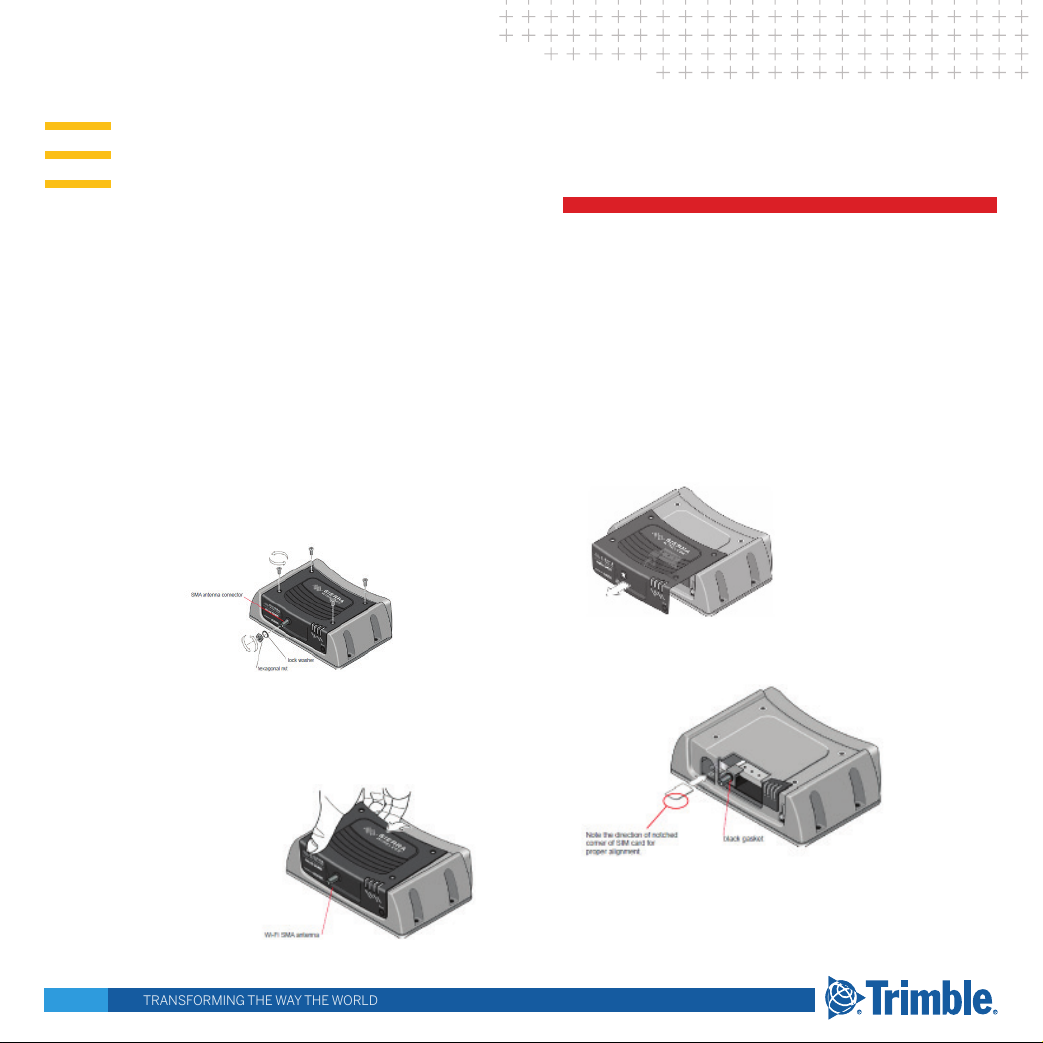
STEP 1: INSTALL THE SIM CARD
1. Ensure the device is powered o.
2. Unscrew the 8 mm hexagonal nut on the WiFi SMA antenna
connector at the front of the gateway, using the socket and
wrench. Then slide o the nut and lock washer. Save the nut
and washer. These are used again.
3. Remove the four screws used to secure the black decorative
cover. Use a Phillips #1 screwdriver. Save the screws for
reinstallation.
4. Gently tilt up the back of the decorative black cover and then
move the cover forward so that it slides over the WiFi SMA
antenna connector.
Warning!
Do not reset the modem to factory defaults.
Do not press and hold the reset button on the front
of the modem.
Do not utilize the web interface to update modem
firmware or perform a factory default reset.
This will remove the custom Trimble firmware and
void the factory warranty.
5. Continue to slide the cover horizontally until it clears the
SMA antenna connector.
6. Lift the cover to remove it completely. Save the cover. It is
used later.
7. Insert the SIM card, with the gold contacts facing down and
the notch on the right side, as shown in the illustration.
Page 2
8. Ensure the black gasket is in place at the base of the SMA
antenna connector.
9. Re-install the decorative black cover:
a. Line up the SMA antenna connector with the hole in the
cover
b. Tilt the rear of the cover slightly to make sure the front
bottom of the cover seats in the front ridge. Slide the cover
into place, and then push the top of the cover down.
c. It may require some force to make sure the 4 holes in the
cover line up with the threaded holes on the top of the
gateway. Push from both the front and the top to line up the
holes properly
d. Use the 4 screws saved in step 2 to re-attach the decorative
black cover. Torque the screws to 5 in-lbs (0.6 N-m). Ensure
that the screws are tight so that the seal underneath the
decorative black cover is tight against the gateway.
e. Place the lock washer onto the SMA antenna connector and
move it to the back of the connector, so it is touching the
decorative black cover.
f. Install, then tighten the nut with a 5/16” or 8 mm socket
torque wrench to a torque specication of 8 in-lbs (0.9 N-m).
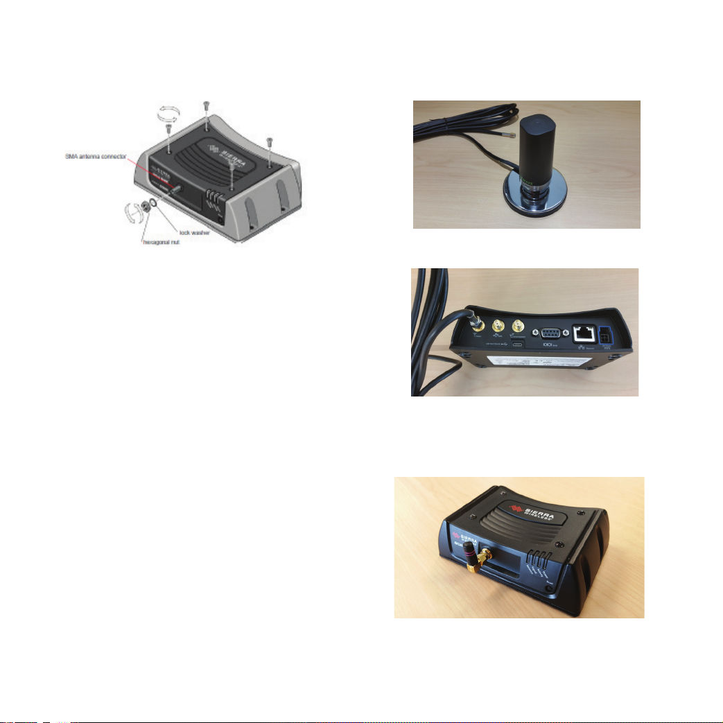
STEP 2: CONNECT THE CELLULAR ANTENNA
1. Attach the supplied antenna to the magnetic antenna base.
Note the rubber o-ring location to ensure a proper seal.
2. Attach the magnetic antenna base cable to the GX450 cellular
connector. The GPS and Diversity connectors will not be used.
STEP 3: CONNECT THE WIFI ANTENNA
Attach the supplied WiFi antenna to the SMA connector on the
front of the gateway (if equipped).
2
Page 3
STEP 4: CONNECT THE DISPLAY OR
RECEIVER
See the wiring diagrams.
In all instances, ensure that the equiopment is powered o
before connecting the modem.
AG-372 receiver
1. Ensure the receiver is powered o.
2. Using cable P/N 109863, attach connector P1 to Port B on the
AG-372 receiver.
3. Attach connector P2 to the serial port on the GX450 modem.
4. Attach connector P3 to the power port on the GX450 modem.
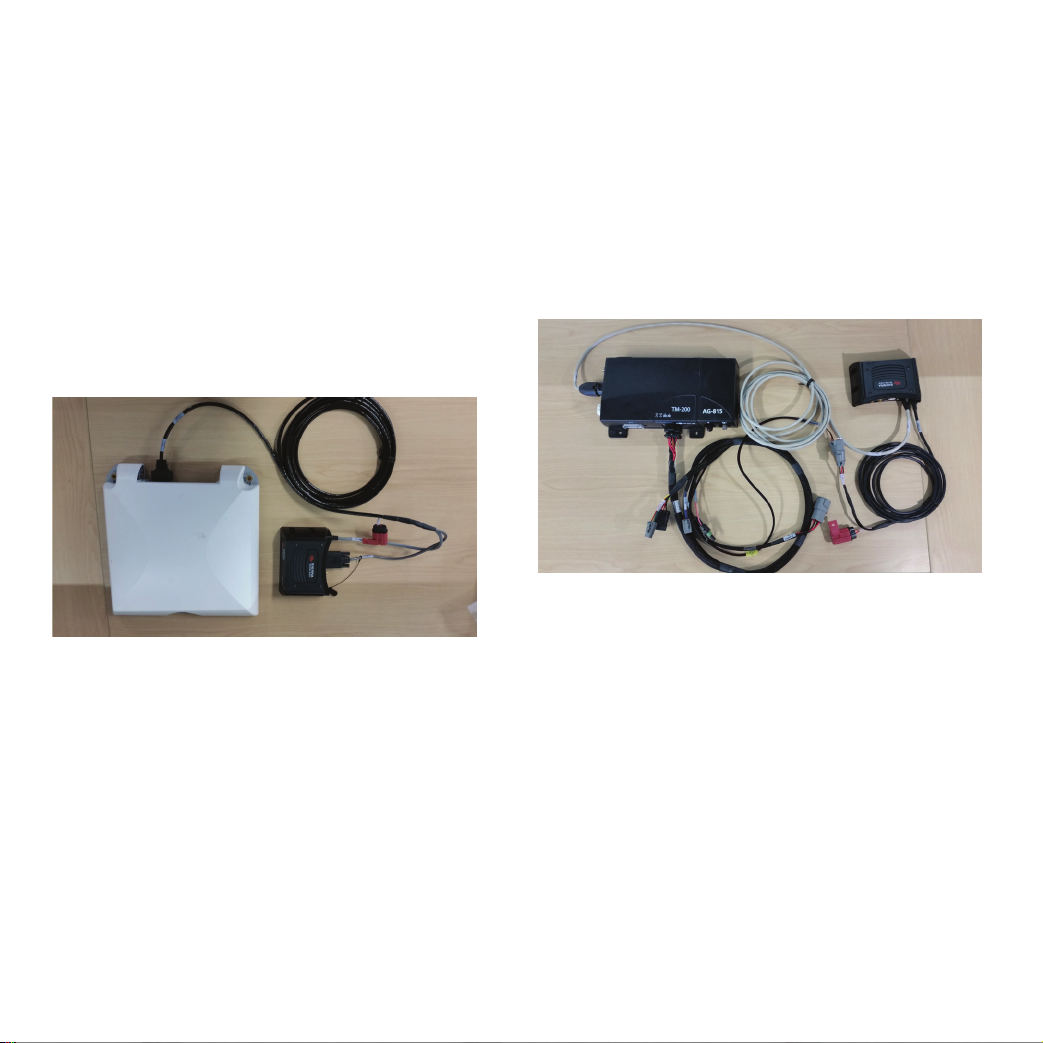
TM-200 Module
1. Ensure the TM-200 Module is powered o.
2. Using cable P/N 109865, attach connector P1 to the Ethernet
port on the GX450 modem and then attach connector P2 to
the Ethernet expansion port on the TM-200 Module or to the
expan-sion port on the EXP-100 Module.
3. Using cable P/N 109862, attach connector P1 to the power port
on the GX450 modem.
4. Connect R1 to P2 on cable P/N 92676 on the TM-200 Module.
5. Attach connector P3 to the power port on the GX450.
3
Page 4

FmX/FM-1000 Integrated Display
1. Ensure the display is powered o.
2. Connect USB hub P/N 83517 to the USB port on the back of
the display.
3. Using cable P/N 109864, attach the USB port to the USB
hub and then attach the micro USB connector to the GX450
modem.
4. Using cable P/N 110832, connect P2 to Port A,B,C,D, or to a
port replicator.
5. Attach connector P1 to connector R1 of cable P/N 109862.
6. Attach connector P1 of cable 109862 to the power port on the
GX450 modem.
CFX-750/FM-750 Display
1. Ensure the display is powered o.
2. Connect the USB hub P/N 83517 to the USB port on the back
of the display.
3. Using cable P/N 109864, attach the USB port to the USB
hub and then attach the micro USB connector to the GX450
modem.
4. Using cable P/N 110832, connect P2 to Port A, B, or to a port
replicator.
5. Attach connector P1 to connector R1 of cable P/N 109862.
6. Attach connector P1 of cable P/N 109862 to the Power port of
the GX450 modem.
4
Page 5

Congure the WiFi Access Point (WiFi modems only)
1. Ensure the display is powered o.
2. Attach connector P1 of cable P/N 109862 to the power port on
the GX450 modem.
3. Attach connector R1 of Cable P/N 109862 to a switched power
source on the power bus P/N 67259, or to another switched
power source on the install kit. The modem should only be
powered when the display is in use.
4. Enter the WiFi setup on your device.
5. Scroll to search for an access point SSID with “TrimGX” in the
name. The correct access point will have numbers similar to
the serial number for the GX450 modem following the TrimGX
prex.
6. When prompted, enter the password for the WiFi. The
password for the WiFi is the 8-digit numerical portion of the
serial number which appears as part of the SSID. Tap Connect.
STEP 5: CONNECT TO THE CELLUAR NETWORK
The rst time the gateway is powered on its home network, it
automatically starts the activation/provisioning process and
attempts to connect to the network. This process typically takes
5-10 minutes. A successful connection is indicated by a solid green
network LED.
5
Page 6

STEP 6: CONFIGURE THE NETWORK
For many cellular carriers, the modem will automatically
congure itself to connect. If issues persist in establishing a
cellular connection (blinking red network LED) the carrier may
require a custom APN to be entered manually. To perform this
task:
1. On a computer powered by a Windows® operating system
(connect to the modem using an Ethernet cable) or using
the modem service tool on the TMX-2050/XCN-2050
display that is connected to the GX450 modem, enter
http://192.168.88.3:9191 in the web browser. The
ACEmanager login screen appears.
2. The administrator username is entered by default. Enter
the default password Wilco2016 and then click Login. The
status/Home screen appears.
4. Click the WAN/Cellular tab, and navigate to the User-
Entered APN section. Enter the custom APN here if the
modem does not automatically detect the cellular
providers APN number.
Note: It may take the gateway 2-3 minutes to respond to the
IP address request following a power cycle.
STEP 7: CONFIGURE THE CORRECTION
SOURCE
Refer to the User Guide for the display or receiver for
information on the setup procedure for VRS setup.
3. Check the Network State eld. It should read Network
Ready, which indicates that the gateway is connected to
the network. If not, refer to STEP 4.
6
Page 7

FIRMWARE VERSION MATRIX
Product Software Version Required
FMX®/FM-1000™ Integrated Display Version 10.01 or later, released December 2016
CFX-750/FM-750 display Version 7.71 or later, released October 2016
TMX-2050™/XCN-2050™ display Version 4.31 or later, released November 2016
AG-372 receiver Version 6.20 or later, released April 2016
GFX-750 Version 1.0 or later, released November 2017
7
Page 8

LED BEHAVIOR
LED Color/Pattern
Power O No power or input voltage ≥ 36 VDC ≤ 9 VDC.
Solid green Gateway is connected to nominal power and is operating normally.
Flashing amber/green Gateway has a GPS x.
Solid amber Gateway is entering a low-power mode or system low-level boot.
Solid red Gateway is not operational (failure or in low-power mode).
Network Solid green Network ready (LTE service available for GX450 modem).
Flashing amber/green Network ready (no LTE service available for GX450 modem).
Flashing green (3 s on, 1 s o) Network ready (WAN over WiFi − gateway in WiFi client mode).
Flashing green (1 s on, 0.5 s o) Network ready - Roaming (LTE service available for GX450 modem).
Flashing amber/green/o Network ready - Roaming (no LTE service available for GX450 modem).
Flashing amber No service.
Solid amber Connecting to network.
Flashing red Authentication/negotiation failed (EV-DO only).
Solid red
Signal Solid green Good signal (RSSI ≥ -85 dBm).
Solid amber Marginal signal (-100 dBm, < RSSI < -85 dBm).
Solid red Poor signal (-110 dBm, ≤ RSSI ≤ -100 dBm).
Flashing red No signal, RSSI (< -100 dBm).
Activity (ALEOS
4.4.0 or later)
O Normal operation.
Flashing green Trac is being transmitted or received over the WAN interface.
Flashing red
Flashing amber
Description
Lilnk down. No cellular network is present, no network coverage at current
location, or the gateway is in radio passthru mode.
Trac is being transmitted or received over the serial port. This behavior only
appears if the AirLink GX Series gateway is congred to display it. Refer to the
ALEOS Software Conguration Guide for details.
Trac is being transmitted or received over both the WAN interface and the serial
port. This behavior only appears if the AirLink GX Series gateway is congured to
display it. Refer to the ALEOS Software Conguration Guide for details.
8
Page 9

9
Page 10

TRANSFORMING THE WAY THE WORLD
EU DECLARATION OF CONFORMITY
Hereby, Sierra Wireless declares that the radio equipment GX450
is in compliance with Directive 2014/53/EU.
The full text of the declaration of conformity is available at the
following internet address:
http://source.sierrawireless.com
Sierra Wireless, 13811 Wireless Way, Richmond, BC, Canada,
V6V3A4
For the complete User Guide, Safety Information and
Certications, go to:
http://source.sierrawireless.com
© 2017. Trimble Inc. All rights reserved. Trimble and the Globe and Triangle logo are
trademarks of Trimble Inc, registered in the United States and in other countries. Autopilot,
Connected Farm, Field-IQ and xFill are trademarks of Trimble Inc.
Version 1.00, Rev A (July 2017).
Trimble Inc.
10368 Westmoor Drive
Westminster CO 80021
USA
10
 Loading...