

Page 1

Sierra Wireless FX30
User Guide
41110030
Rev 4
Page 2

Sierra Wireless FX30 User Guide
Important
Notice
Safety and
Hazards
Limitation of
Liability
Due to the nature of wireless communications, transmission and reception of data
can never be guaranteed. Data may be delayed, corrupted (i.e., have errors) or be
totally lost. Although significant delays or losses of data are rare when wireless
devices such as the Sierra Wireless modem are used in a normal manner with a
well-constructed network, the Sierra Wireless modem should not be used in
situations where failure to transmit or receive data could result in damage of any
kind to the user or any other party, including but not limited to personal injury,
death, or loss of property. Sierra Wireless accepts no responsibility for damages
of any kind resulting from delays or errors in data transmitted or received using
the Sierra Wireless modem, or for failure of the Sierra Wireless modem to
transmit or receive such data.
Do not operate the Sierra Wireless modem in areas where blasting is in progress,
near medical equipment, near life support equipment, or any equipment which
may be susceptible to any form of radio interference. In such areas, the Sierra
Wireless modem MUST BE POWERED OFF. The Sierra Wireless modem can
transmit signals that could interfere with this equipment.
The driver or operator of any vehicle should not operate the Sierra Wireless
modem while in control of a vehicle. Doing so will detract from the driver or
operator's control and operation of that vehicle. In some states and provinces,
operating such communications devices while in control of a vehicle is an offence.
The information in this manual is subject to change without notice and does not
represent a commitment on the part of Sierra Wireless. SIERRA WIRELESS AND
ITS AFFILIATES SPECIFICALLY DISCLAIM LIABILITY FOR ANY AND ALL
DIRECT, INDIRECT, SPECIAL, GENERAL, INCIDENTAL, CONSEQUENTIAL,
PUNITIVE OR EXEMPLARY DAMAGES INCLUDING, BUT NOT LIMITED TO,
LOSS OF PROFITS OR REVENUE OR ANTICIPATED PROFITS OR REVENUE
ARISING OUT OF THE USE OR INABILITY TO USE ANY SIERRA WIRELESS
PRODUCT, EVEN IF SIERRA WIRELESS AND/OR ITS AFFILIATES HAS BEEN
ADVISED OF THE POSSIBILITY OF SUCH DAMAGES OR THEY ARE
FORESEEABLE OR FOR CLAIMS BY ANY THIRD PARTY.
Notwithstanding the foregoing, in no event shall Sierra Wireless and/or its
affiliates aggregate liability arising under or in connection with the Sierra Wireless
product, regardless of the number of events, occurrences, or claims giving rise to
liability, be in excess of the price paid by the purchaser for the Sierra Wireless
product.
Patents This product may contain technology developed by or for Sierra Wireless Inc. This
product includes technology licensed from QUALCOMM
manufactured or sold by Sierra Wireless Inc. or its affiliates under one or more
patents licensed from MMP Portfolio Licensing.
®
. This product is
Copyright © 2019 Sierra Wireless. All rights reserved.
Trademarks Sierra Wireless
trademarks of Sierra Wireless.
Rev 4 March 2019 2 41110030
®
, Legato®, and the Sierra Wireless logo are registered
Page 3

Contact
Information
Windows® is a registered trademarks of Microsoft Corporation.
®
Linux
is the registered trademark of Linus Torvalds in the U.S. and other
countries.
Macintosh
®
and Mac OS X® are registered trademarks of Apple Inc., registered in
the U.S. and other countries.
QUALCOMM
®
is a registered trademark of QUALCOMM Incorporated. Used
under license.
Other trademarks are the property of their respective owners.
Sales information and technical
support, including warranty and returns
Corporate and product information Web: sierrawireless.com
Web: sierrawireless.com/company/contact-us/
Global toll-free number: 1-877-687-7795
6:00 am to 5:00 pm PST
Preface
Rev 4 March 2019 3 41110030
Page 4

Contents
Introduction to the FX30 . . . . . . . . . . . . . . . . . . . . . . . . . . . . . . . . . . . . . . . . . . . . . . . . . . .7
Key Features . . . . . . . . . . . . . . . . . . . . . . . . . . . . . . . . . . . . . . . . . . . . . . . . . . . . . . . . . 7
Power Modes . . . . . . . . . . . . . . . . . . . . . . . . . . . . . . . . . . . . . . . . . . . . . . . . . . . . . . . . . 8
Accessories . . . . . . . . . . . . . . . . . . . . . . . . . . . . . . . . . . . . . . . . . . . . . . . . . . . . . . . . . . 8
Warranty. . . . . . . . . . . . . . . . . . . . . . . . . . . . . . . . . . . . . . . . . . . . . . . . . . . . . . . . . . . . . 9
Reference Documents . . . . . . . . . . . . . . . . . . . . . . . . . . . . . . . . . . . . . . . . . . . . . . . . . . 9
Installation and Startup . . . . . . . . . . . . . . . . . . . . . . . . . . . . . . . . . . . . . . . . . . . . . . . . . .10
Tools and Materials Required. . . . . . . . . . . . . . . . . . . . . . . . . . . . . . . . . . . . . . . . . . . . 10
Optional Software . . . . . . . . . . . . . . . . . . . . . . . . . . . . . . . . . . . . . . . . . . . . . . . . . . . . . 10
Installation Overview . . . . . . . . . . . . . . . . . . . . . . . . . . . . . . . . . . . . . . . . . . . . . . . . . . 10
Step 1—Insert the SIM Card and Optional IoT Card . . . . . . . . . . . . . . . . . . . . . . . . . . 11
Step 2—Mount and Ground the FX30 Chassis . . . . . . . . . . . . . . . . . . . . . . . . . . . . . . 12
Flat Mount . . . . . . . . . . . . . . . . . . . . . . . . . . . . . . . . . . . . . . . . . . . . . . . . . . . . . . . .13
Optional—Mounting in a High Vibration Environment . . . . . . . . . . . . . . . . . . . . . . .14
Mounting on a DIN Rail . . . . . . . . . . . . . . . . . . . . . . . . . . . . . . . . . . . . . . . . . . . . . .16
Replacing Existing Fastrack Supreme or Fastrack Xtend Device . . . . . . . . . . . . . .16
Step 3—Connect the Antennas . . . . . . . . . . . . . . . . . . . . . . . . . . . . . . . . . . . . . . . . . . 18
Step 4—Connect the Data Cables. . . . . . . . . . . . . . . . . . . . . . . . . . . . . . . . . . . . . . . . 20
Cabling Concerns . . . . . . . . . . . . . . . . . . . . . . . . . . . . . . . . . . . . . . . . . . . . . . . . . . . . . 20
Cable Strain Relief . . . . . . . . . . . . . . . . . . . . . . . . . . . . . . . . . . . . . . . . . . . . . . . . . .20
Step 5—Connect the Power and I/O . . . . . . . . . . . . . . . . . . . . . . . . . . . . . . . . . . . . . . 21
Fusing . . . . . . . . . . . . . . . . . . . . . . . . . . . . . . . . . . . . . . . . . . . . . . . . . . . . . . . . . . .21
Power and I/O Connections . . . . . . . . . . . . . . . . . . . . . . . . . . . . . . . . . . . . . . . . . . .21
Wiring Diagrams . . . . . . . . . . . . . . . . . . . . . . . . . . . . . . . . . . . . . . . . . . . . . . . . . . . .23
I/O Configuration . . . . . . . . . . . . . . . . . . . . . . . . . . . . . . . . . . . . . . . . . . . . . . . . . . . . . 25
I/O Pins . . . . . . . . . . . . . . . . . . . . . . . . . . . . . . . . . . . . . . . . . . . . . . . . . . . . . . . . . .25
Step 6—Check the FX30 Operation . . . . . . . . . . . . . . . . . . . . . . . . . . . . . . . . . . . . . . 29
LED Behavior . . . . . . . . . . . . . . . . . . . . . . . . .
. . . . . . . . . . . . . . . . . . . . . . . . . . . . .30
Ethernet LEDs . . . . . . . . . . . . . . . . . . . . . . . . . . . . . . . . . . . . . . . . . . . . . . . . . . . . .30
Step 7—Use the FX30 . . . . . . . . . . . . . . . . . . . . . . . . . . . . . . . . . . . . . . . . . . . . . . . . . 31
Using the FX30 as an Embedded Platform for IoT Applications . . . . . . . . . . . . . . .31
Rev 4 March 2019 4 41110030
Page 5

Contents
Setup for Windows. . . . . . . . . . . . . . . . . . . . . . . . . . . . . . . . . . . . . . . . . . . . . . . . . . . . 31
Useful AT Commands . . . . . . . . . . . . . . . . . . . . . . . . . . . . . . . . . . . . . . . . . . . . . . . . . 32
Setup for Linux Shell Commands . . . . . . . . . . . . . . . . . . . . . . . . . . . . . . . . . . . . . . . . 32
Useful Linux commands . . . . . . . . . . . . . . . . . . . . . . . . . . . . . . . . . . . . . . . . . . . . . 33
Linux Interface Mapping . . . . . . . . . . . . . . . . . . . . . . . . . . . . . . . . . . . . . . . . . . . . . 34
Linux Startup . . . . . . . . . . . . . . . . . . . . . . . . . . . . . . . . . . . . . . . . . . . . . . . . . . . . . . 34
Managing the I/O Interface . . . . . . . . . . . . . . . . . . . . . . . . . . . . . . . . . . . . . . . . . . . . . 34
Legato Application Framework . . . . . . . . . . . . . . . . . . . . . . . . . . . . . . . . . . . . . . . . . . 34
AirVantage IoT Platform. . . . . . . . . . . . . . . . . . . . . . . . . . . . . . . . . . . . . . . . . . . . . . . . 35
Reset to Factory Default Settings . . . . . . . . . . . . . . . . . . . . . . . . . . . . . . . . . . . . . . . . 36
Specifications . . . . . . . . . . . . . . . . . . . . . . . . . . . . . . . . . . . . . . . . . . . . . . . . . . . . . . . . . . 37
Radio Frequency Bands . . . . . . . . . . . . . . . . . . . . . . . . . . . . . . . . . . . . . . . . . . . . . . . 39
Radio Module Conducted Transmit Power . . . . . . . . . . . . . . . . . . . . . . . . . . . . . . . . . 42
Mechanical Specifications . . . . . . . . . . . . . . . . . . . . . . . . . . . . . . . . . . . . . . . . . . . . . . 45
Power Modes. . . . . . . . . . . . . . . . . . . . . . . . . . . . . . . . . . . . . . . . . . . . . . . . . . . . . . . . 47
OFF Mode . . . . . . . . . . . . . . . . . . . . . . . . . . . . . . . . . . . . . . . . . . . . . . . . . . . . . . . . 47
Ultra Low Power Mode . . . . . . . . . . . . . . . . . . . . . . . . . . . . . . . . . . . . . . . . . . . . . . 48
Active Mode . . . . . . . . . . . . . . . . . . . . . . . . . . . . . . . . . . . . . . . . . . . . . . . . . . . . . . . 48
Power Consumption. . . . . . . . . . . . . . . . . . . . . . . . . . . . . . . . . . . . . . . . . . . . . . . . . . . 49
Internet of Things (IoT) Expansion Card . . . . . . . . . . . . . . . . . . . . . . . . . . . . . . . . . . . 51
For IoT Expansion Card Developers . . . . . . . . . . . . . . . . . . . . . . . . . . . . . . . . . . . . 52
Pin-out Information . . . . . . . . . . . . . . . . . . . . . . . . . . . . . . . . . . . . . . . . . . . . . . . . . 53
IoT Connector Interface . . . . . . . . . . . . . . . . . . . . . . . . . . . . . . . . . . . . . . . . . . . . . . 54
Regulatory Information . . . . . . . . . . . . . . . . . . . . . . . . . . . . . . . . . . . . . . . . . . . . . . . . . . 55
Important Information for North American Users . . . . . . . . . . . . . . . . . . . . . . . . . . . . . 55
RF Exposure . . . . . . . . . . . . . . . . . . . . . . . . . . . . . . . . . . . . . . . . . . . . . . . . . . . . . . 55
EU . . . . . . . . . . . . . . . . . . . . . . . . . . . . . . . . . . . . . . . . . . . . . . . . . . . . . . . . . . . . . . . . 57
Accessories . . . . . . . . . . . . . . . . . . . . . . . . . . . . . . . . . . . . . . . . . . . . . . . . . . . . . . . . . .
. 58
DC Power Cable (Black Connector) . . . . . . . . . . . . . . . . . . . . . . . . . . . . . . . . . . . . . . 58
Rev 4 March 2019 5 41110030
Page 6

Sierra Wireless FX30 User Guide
AC Power Adapter (Black Connector) . . . . . . . . . . . . . . . . . . . . . . . . . . . . . . . . . . . . . 59
AC Power Adapter Input . . . . . . . . . . . . . . . . . . . . . . . . . . . . . . . . . . . . . . . . . . . . . 59
AC Power Adapter Output . . . . . . . . . . . . . . . . . . . . . . . . . . . . . . . . . . . . . . . . . . . . 59
Environmental Specifications . . . . . . . . . . . . . . . . . . . . . . . . . . . . . . . . . . . . . . . . . 59
Reliability and Quality Control . . . . . . . . . . . . . . . . . . . . . . . . . . . . . . . . . . . . . . . . . 60
Safety Standards . . . . . . . . . . . . . . . . . . . . . . . . . . . . . . . . . . . . . . . . . . . . . . . . . . . 60
EMC Standards . . . . . . . . . . . . . . . . . . . . . . . . . . . . . . . . . . . . . . . . . . . . . . . . . . . . 60
Hazardous Substances . . . . . . . . . . . . . . . . . . . . . . . . . . . . . . . . . . . . . . . . . . . . . . 60
Energy Efficiency . . . . . . . . . . . . . . . . . . . . . . . . . . . . . . . . . . . . . . . . . . . . . . . . . . . 61
Using the FX30 as a USB Modem . . . . . . . . . . . . . . . . . . . . . . . . . . . . . . . . . . . . . . . . . 62
AT Commands Reference. . . . . . . . . . . . . . . . . . . . . . . . . . . . . . . . . . . . . . . . . . . . . . . . 65
Managing the I/O Interface with AT Commands . . . . . . . . . . . . . . . . . . . . . . . . . . . . . 65
FX30 Linux Interface and GPIO Mapping . . . . . . . . . . . . . . . . . . . . . . . . . . . . . . . . . . . 73
WP Module Internal GPIO Mapping. . . . . . . . . . . . . . . . . . . . . . . . . . . . . . . . . . . . . . . 76
FX30 Factory Configuration . . . . . . . . . . . . . . . . . . . . . . . . . . . . . . . . . . . . . . . . . . . . . . 78
eSIM support . . . . . . . . . . . . . . . . . . . . . . . . . . . . . . . . . . . . . . . . . . . . . . . . . . . . . . . . 78
AUTO-SIM . . . . . . . . . . . . . . . . . . . . . . . . . . . . . . . . . . . . . . . . . . . . . . . . . . . . . . . . . . 78
SIM AUTO SWITCH . . . . . . . . . . . . . . . . . . . . . . . . . . . . . . . . . . . . . . . . . . . . . . . . . . 78
AirVantage Management Services Polling Mode. . . . . . . . . . . . . . . . . . . . . . . . . . . . . 79
AirVantage Management Services User Agreements . . . . . . . . . . . . . . . . . . . . . . . . . 79
UART Settings . . . . . . . . . . . . . . . . . . . . . . . . . . . . . . . . . . . . . . . . . . . . . . . . . . . . . . . 79
Index. . . . . . . . . . . . . . . . . . . . . . . . . . . . . . . . . . . . . . . . . . . . . . . . . . . . . . . . . . . . . . . . . 80
Rev 4 March 2019 6 41110030
Page 7

1: Introduction to the FX30
1
The Sierra Wireless® FX30, a small, rugged, programmable Internet of Things (IoT)
gateway, runs the secure Legato
®
Linux
operating system. You can use the FX30 as a simple USB modem, but its full
potential is realized when you use it as an embedded cellular platform for IoT
applications. With Ethernet, USB, I/O interfaces, and IoT Expansion cards, the FX30
can connect to many machines and infrastructures. The Linux-based Legato
framework enables you to use efficient low-level C programming to write IoT
applications for any connected machine.
®
Application Framework, and a long-term support
Key Features
• Broad range of LTE & 3G Radio Technologies available (radio module dependent)
The following FX30 variants are currently available:
· Penta-band HSPA+ (WP8548)
· LTE Cat-1 (WP7601-1, WP7603-1, WP7607-1)
· LTE Cat-M1 (WP7702)
• Ethernet 10/100 Mbps
• USB 2.0
• mini-SIM slot
• Three configurable I/Os
• Internet of Things (IoT) slot
• GNSS (GPS/Galileo / GLONASS/BeiDou
• Legato support
• Ultra low power mode
1
)
1. Support varies depending on radio module
Rev 4 March 2019 7 41110030
Page 8
Sierra Wireless FX30 User Guide
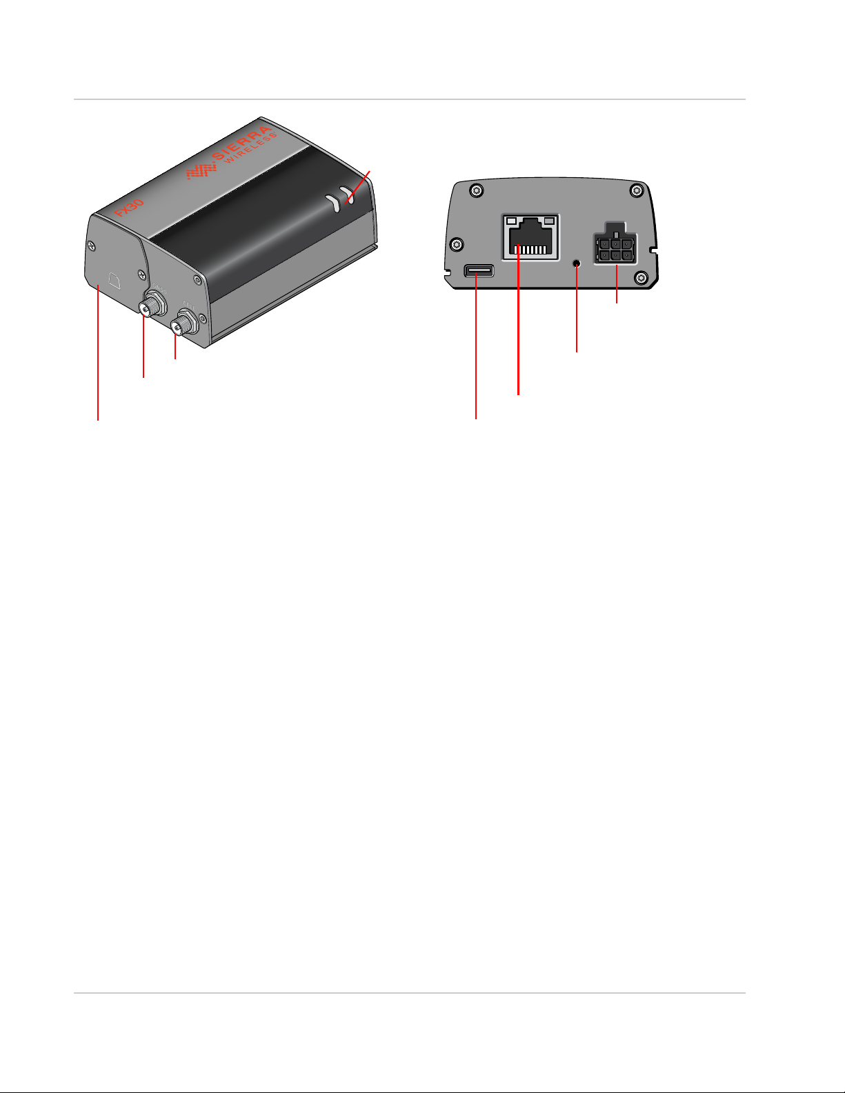
Power Connector
(See Power Connector
on page 21.)
SIM card/IoT card holder
(See Install SIM card and IoT card on page 11.)
Cellular Antenna Connector
USB 2.0 Micro-B Port
(See Connect the Antennas on page 18.)
(See Connect the Data Cables on page 20.)
RJ-45 Ethernet Port
GNSS Antenna Connector
LEDs (See LED Behavior
on page 30.)
Push Button
(See External Push Button
on page 74.)
Rev 4 March 2019 8 41110030
Figure 1-1: FX30 Connectors, LEDs and SIM Card Holder
Power Modes
FX30 has three power modes:
• Off
• Ultra Low Power
• Active
For more information on power modes and power consumption, see Power
Modes on page 47 and Power Consumption on page 49.
Accessories
The following items come with the FX30 gateway:
• DC power cable
• Mounting bracket
You can order the following items separately from Sierra Wireless:
• Universal AC power adapter
• Compatibility bar (useful if you are replacing a Fastrack Supreme or a
• Range of GNSS and cellular antennas
· Voltage input: 100– 240 VAC
· Current output: 1.5 A
Fastrack Xtend)
· Puck antenna (Cell & GNSS; part number 6001128) is recommended
Page 9

Introduction to the FX30
If you are mounting the FX30 on a DIN rail, you will also need 35 mm DIN rail
clips.
For more information, see Accessories on page 58.
Warranty
The FX30 comes with a 3-year warranty.
Reference Documents
Document
Number
4116440 WP75xx/WP8548 Product Technical Specification
4119652 WP76xx Product Technical Specification
41111 420 WP77xx Product Technical Specification
4118047 WP8548/WP75xx/WP76xx/WP77xx AT Command Reference
4117166 IoT Expansion Card Design Specification
n/a Legato information
Title
Rev 4 March 2019 9 41110030
Page 10

2: Installation and Startup
This chapter shows how to connect, install and start the Sierra Wireless FX30. It also
describes the front panel LEDs and I/O functionality.
Note: The FX30 must be installed by a qualified technician.
Tools and Materials Required
• mini-SIM card (provided by your mobile network operator)
• #1 Phillips screwdriver
• Laptop computer
• AC adapter or DC power cable
• micro-B USB cable
• Cellular antenna
• GNSS antenna (optional)
Optional Software
Depending on your operating environment, you may want to download and install the
following software:
• Windows USB driver—Install the USB drivers for WP Series modules, available
from http://source.sierrawireless.com/devices/fx-series/FX30/ (in the Software
section under Windows drivers).
• A Windows terminal emulator program such as Tera Term.
2
Installation Overview
The steps for a typical installation are:
1. Insert the SIM card and optional IoT Expansion card.
2. Mount and ground the FX30.
3. Connect the antennas.
4. Connect the data cables.
5. Connect the power and I/ O.
6. Check the FX30 operation.
7. Use the FX30.
The following sections describe these steps in detail. Read these sections carefully
before performing the installation.
Rev 4 March 2019 10 41110030
Page 11
Installation and Startup
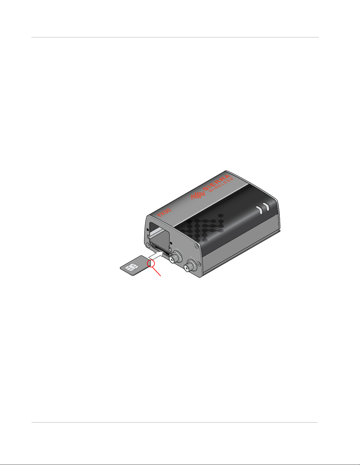
Note the location of the notch
Step 1—Insert the SIM Card and Optional IoT Card
The Sierra Wireless FX30 has one mini-SIM (2FF) card slot.
If the SIM card has not already been installed, insert the SIM card into the
gateway before connecting any external equipment or power to the FX30.
To install the SIM card:
1. Use a Phillips screwdriver to remove the cover.
2. Orient the SIM card, as shown in Figure 2-1. The gold contacts on the SIM
card face up.
3. Gently slide the SIM card into the slot until it clicks into place.
To remove the SIM card, press it in, and release it. Gently grip the SIM card
and pull it out.
Rev 4 March 2019 11 41110030
Figure 2-1: Installing the SIM card
4. Reattach the cover.
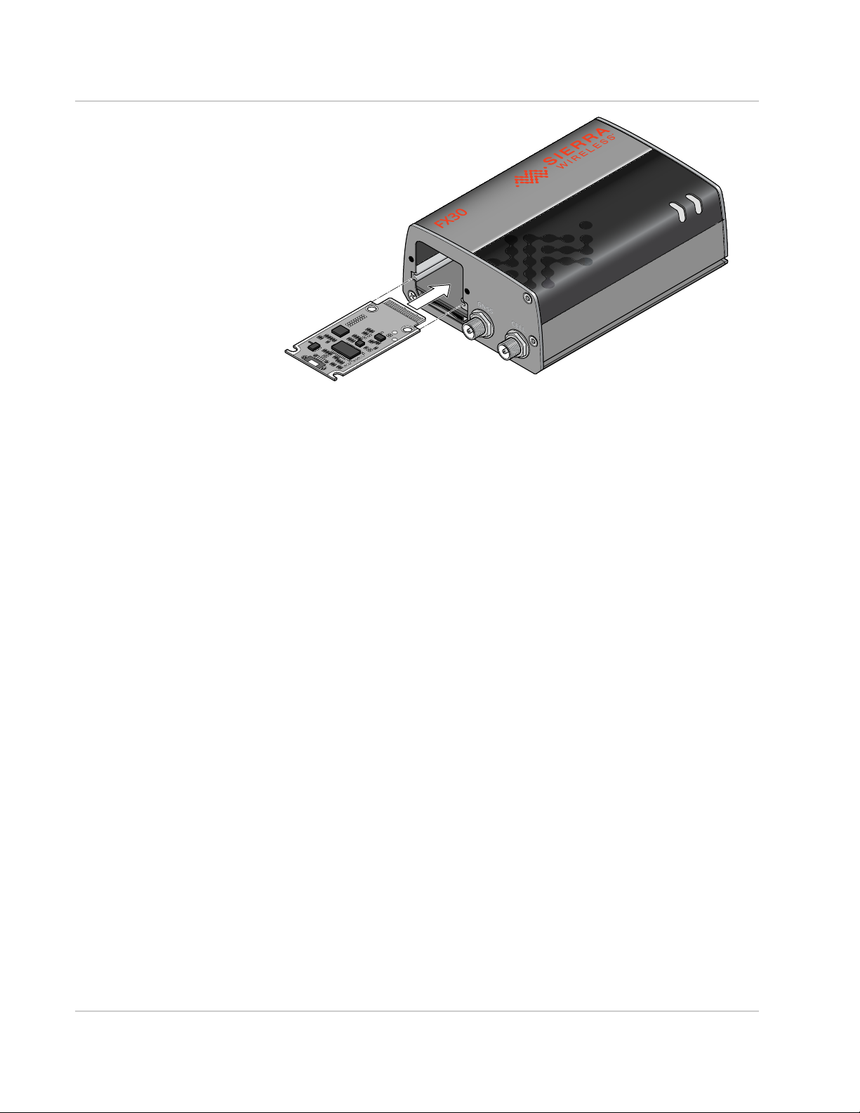
The FX30 has a slot for an Internet of Things (IoT) Expansion card that provides a
standard hardware interface for sensors, network adapters and other IoT
technologies. Using Legato, you can design host applications for the IoT
Expansion Card. For more information, see Internet of Things (IoT) Expansion
Card on page 51.
To install an IoT Expansion card:
1. Use a Phillips screwdriver to remove the SIM card/IoT Expansion card cover.
2. Orient the IoT Expansion card as shown in Figure 2-2 and slide the card into
the IoT slot.
3. Reattach the cover.
Page 12
Sierra Wireless FX30 User Guide
Figure 2-2: Installing the IoT Expansion card
Step 2—Mount and Ground the FX30 Chassis
You can flat mount the FX30 or mount it on a DIN rail. An optional compatibility
bar allows you to use existing mounting holes if you are replacing a Fastrack
Supreme or a Fastrack Xtend programmable gateway. See Replacing Existing
Fastrack Supreme or Fastrack Xtend Device on page 16.
Mount the FX30 where:
• There is easy access for attaching the cables.
• Cables will not be constricted, close to high amperages, or exposed to
extreme temperatures.
• The front panel LEDs are easily visible.
• There is adequate airflow.
• It is away from direct exposure to the elements such as sun, rain, dust, etc.
You can mount the FX30:
• On a flat surface (page 13)
• On a DIN Rail (page 16)
Rev 4 March 2019 12 41110030
Page 13
Installation and Startup
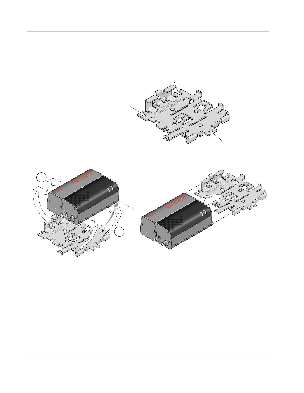
Attachment point
Attachment point
Attachment point
1
2
Recommended: Snap the gateway onto the bracket.
Alternative: If access space is limited, slide the gateway onto the bracket.
Flat Mount
To mount the FX30 on a flat surface:
1. Attach the bracket to the mounting surface, using the attachment points
shown in Figure 2-3.
Figure 2-3: Mounting Bracket, showing attachment points
2. Snap or slide the FX30 onto the bracket.
Rev 4 March 2019 13 41110030
Figure 2-4: Attaching the FX30 to the bracket
Page 14
Sierra Wireless FX30 User Guide
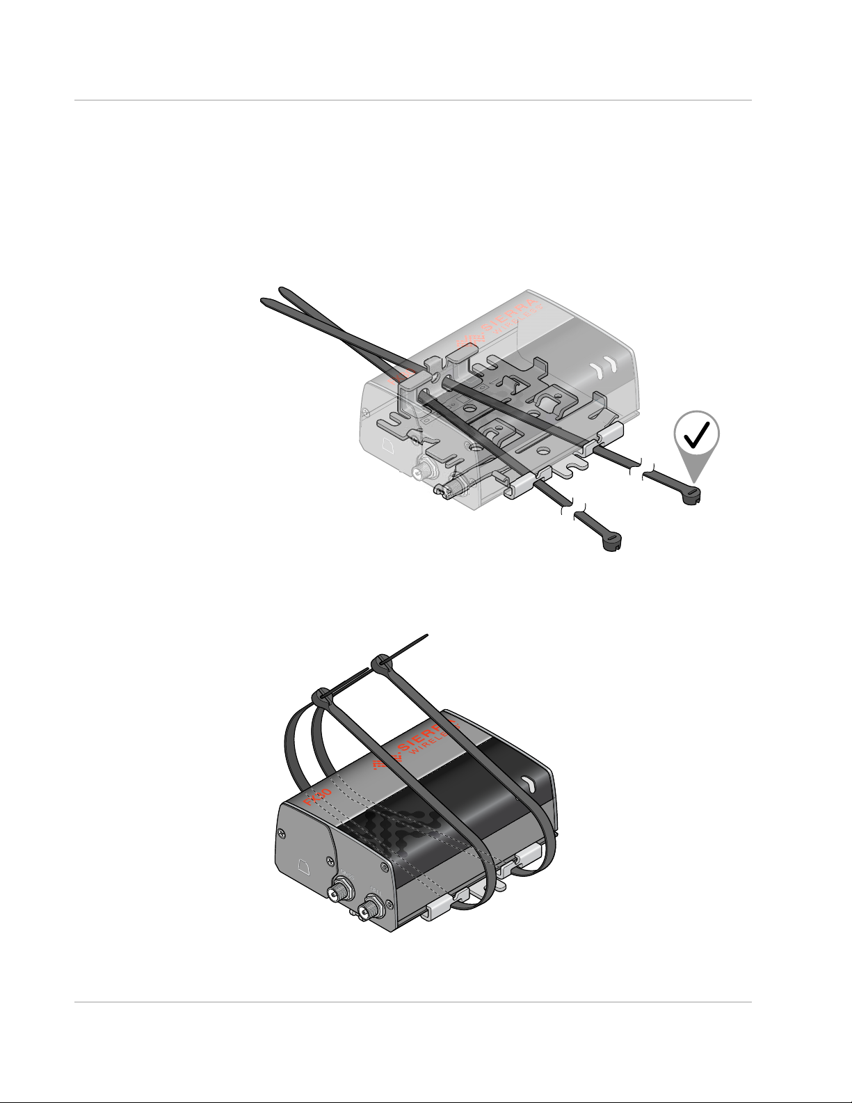
Optional— Mounting in a High Vibration Environment
If you are mounting the FX30 in a high vibration area, Sierra Wireless strongly
recommends using two nylon cable ties to secure the FX30 on the bracket.
To secure the FX30 on the bracket:
1. Thread the ties into the holes on one side of the bracket and out the holes on
the other side of the bracket, as shown in Figure 2-5 on page 14.
Figure 2-5: Inserting the cable ties
2. Wrap the ties around the FX30 and insert the pointed ends of the ties into the
blunt ends.
Figure 2-6: Inserting the ends of the ties
Rev 4 March 2019 14 41110030
Page 15
Installation and Startup
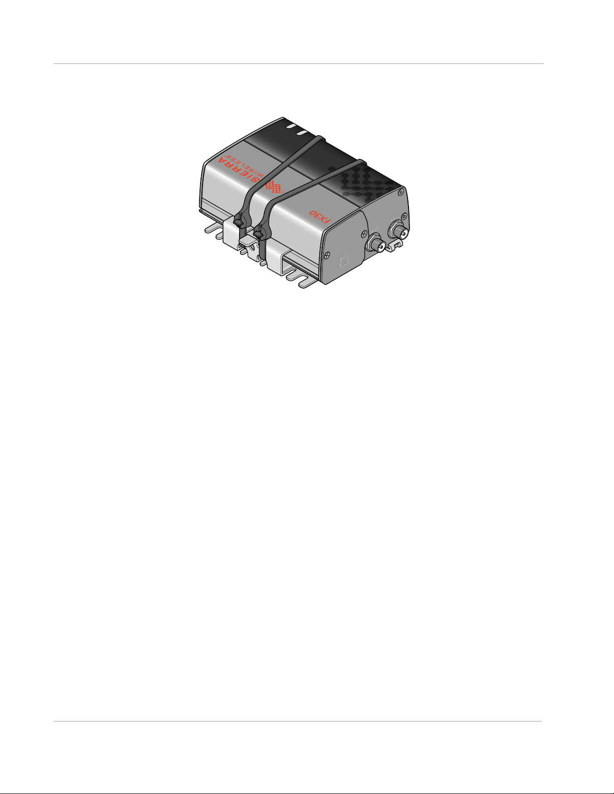
3. Tighten and secure the ties around the FX30 and trim off the excess length of
the ties.
Figure 2-7: Cable ties tightened and trimmed
4. You are now ready to flat mount the FX30 in a high vibration environment. If
you are mounting it on a DIN rail, see Mounting on a DIN Rail on page 16.
Rev 4 March 2019 15 41110030
Page 16
Sierra Wireless FX30 User Guide
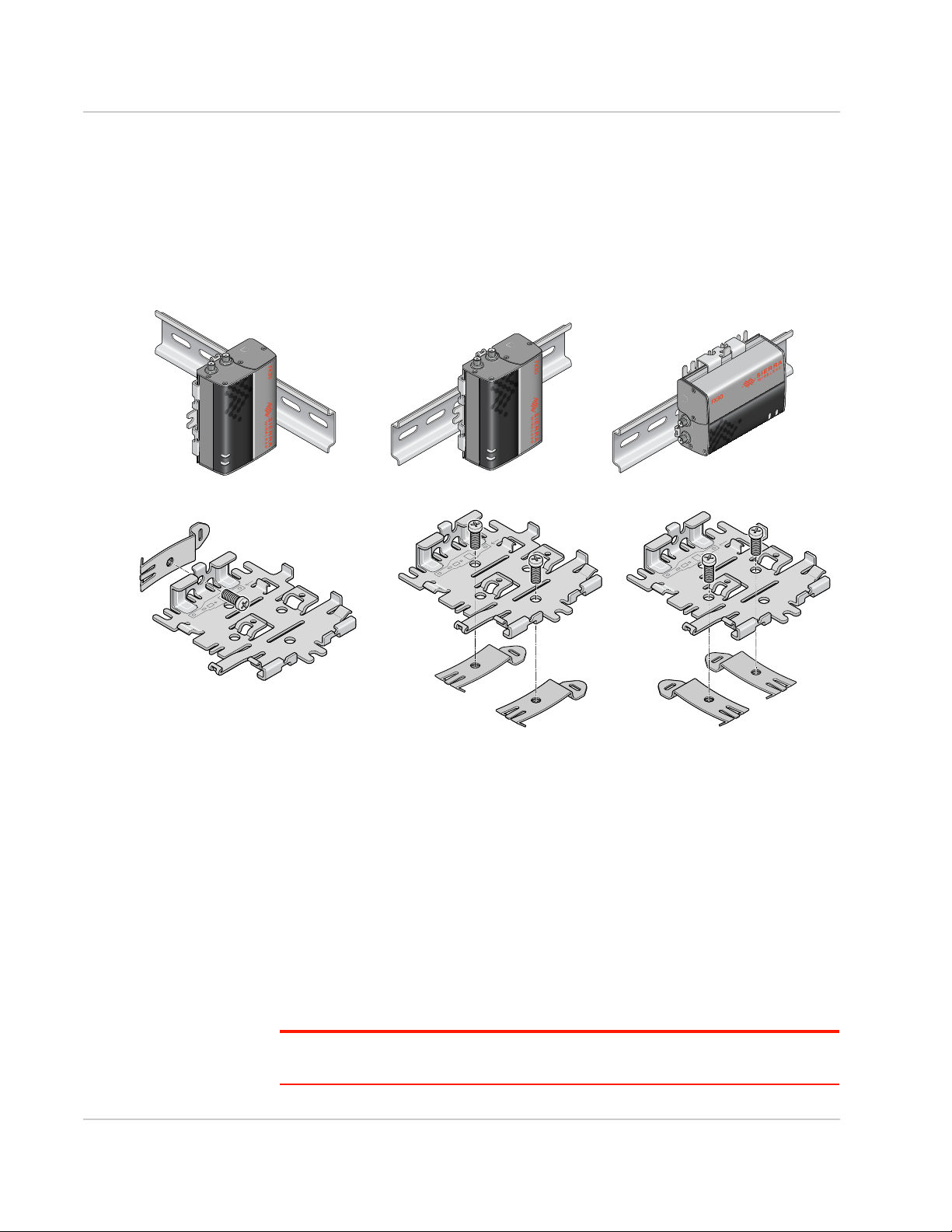
For this orientation, attach one DIN
rail clip to the side of the bracket.
For these orientations, attach two DIN rail clips to the bottom of the bracket.
Mounting on a DIN Rail
To mount the FX30 in a DIN rail:
1. Attach the DIN rail clips to the bracket as shown in Figure 2-8.
If you are mounting the FX30 on its edge, attach one DIN rail clip to the side of
the bracket.
If you are mounting the FX30 horizontally or vertically, attach two DIN rail clips
to the bottom of the bracket.
Rev 4 March 2019 16 41110030
Figure 2-8: Attaching the DIN rail clips
2. Slide or snap the FX30 onto the bracket, as shown in Figure 2-4.
3. If the DIN rails are in a high vibration environment, see Optional—Mounting
in a High Vibration Environment on page 14.
4. Attach the FX30 to the DIN Rail. See Figure 2-8.
Replacing Existing Fastrack Supreme or Fastrack Xtend Device
If you are mounting the FX30 in a location where you previously had a Fastrack
Supreme or a Fastrack Xtend mounted, attach the compatibility bar to the bracket.
The compatibility bar is available from Sierra Wireless.
Note: Adding the compatibility bar does not change the height of the gateway and
mounting bracket. See Figure 3-2 on page 46.
Page 17
Installation and Startup
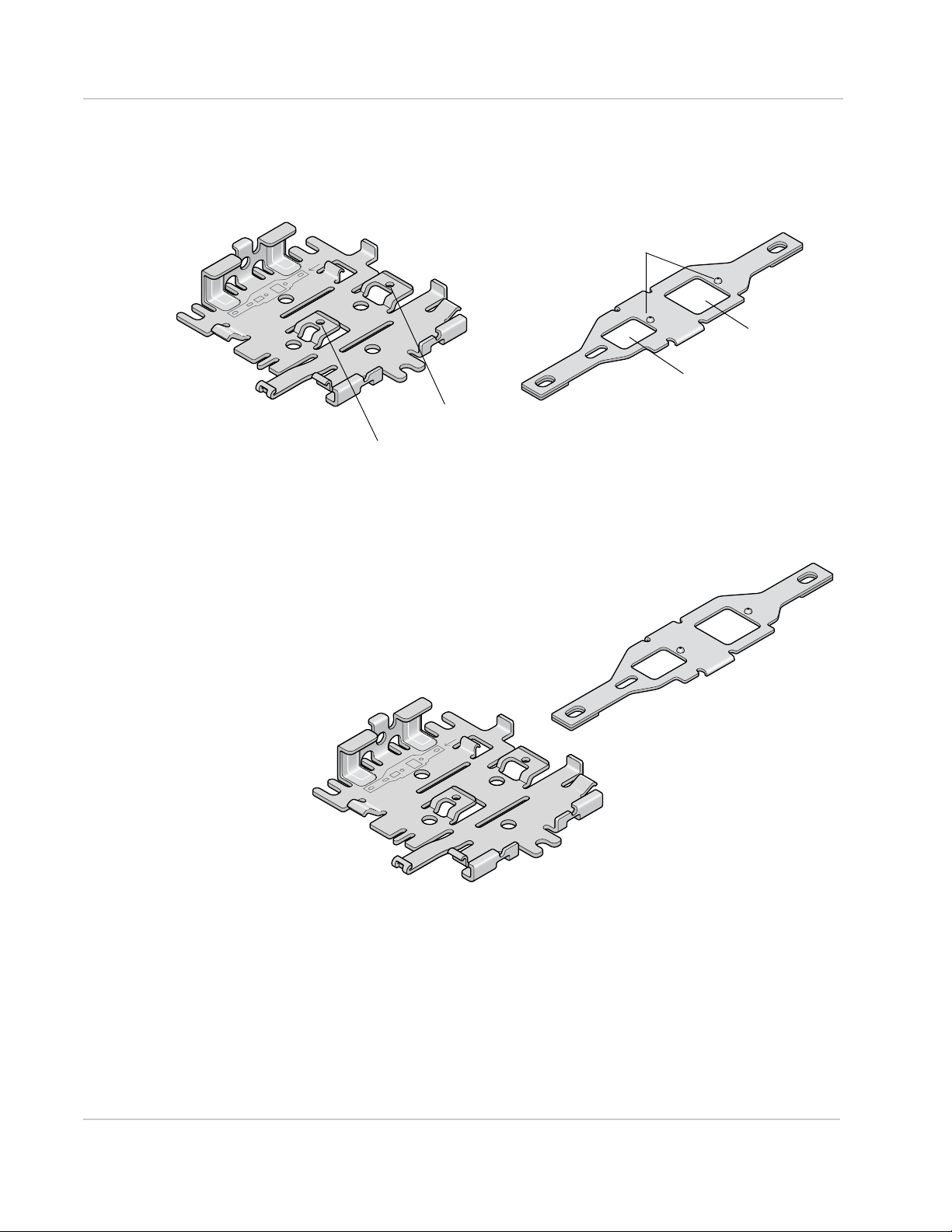
Mounting bracket
Compatibility bar
Small raised tab
Small opening
Large opening
Small raised knobs
Large raised tab
with small hole
with small hole
To attach the compatibility bar to the bracket:
1. Note the large and small raised tabs on the bracket. Each tab has a small
hole in the center of the raised portion. Also note the large and small rectangular openings in the compatibility bar. See Figure 2-9.
Figure 2-9: Mounting bracket and compatibility bar
2. Orient the mounting bracket and the compatibility bar as shown in
Figure 2-10.
Figure 2-10: Mounting bracket and compatibility bar orientation
3.
Place the compatibility bar on top of the bracket, so that the tabs on the
bracket are inside the openings in the bar, and slide the bar into place. When
fully secure, the knobs on the bar should be inside the small holes on the tabs.
Rev 4 March 2019 17 41110030
Page 18

Sierra Wireless FX30 User Guide
Raised flaps
Mounting bracket
Compatibility bar
Raised knobs
Mounting holes
Figure 2-11: Attaching the compatibility bar
4. The mounting holes in the adapter bar match the existing mounting holes for
the Fastrack Supreme or Fastrack Xtend.
For DC installations (with a fixed “system” ground reference), Sierra Wireless
recommends always grounding the FX30 chassis to this system ground
reference.
To ensure a good grounding reference, attach the FX30 to a grounded metallic
surface.
Step 3—Connect the Antennas
Warning: This gateway is not intended for use close to the human body. Antennas
should be at least 8 inches (20 cm) away from the operator.
The FX30 has two SMA female antenna connectors:
• Cellular antenna connector
• GNSS antenna connector
GNSS bias supports 3.15 V antennas
For regulatory requirements concerning antennas, see Maximum Antenna Gain
on page 55.
Rev 4 March 2019 18 41110030
Note: The antenna should not exceed the maximum gain specified in RF Exposure on
page 55. In more complex installations (such as those requiring long lengths of cable and/
or multiple connections), you must follow the maximum dBi gain guidelines specified by the
radio communications regulations of the Federal Communications Commission (FCC),
Industry Canada, or your country’s regulatory body.
Page 19
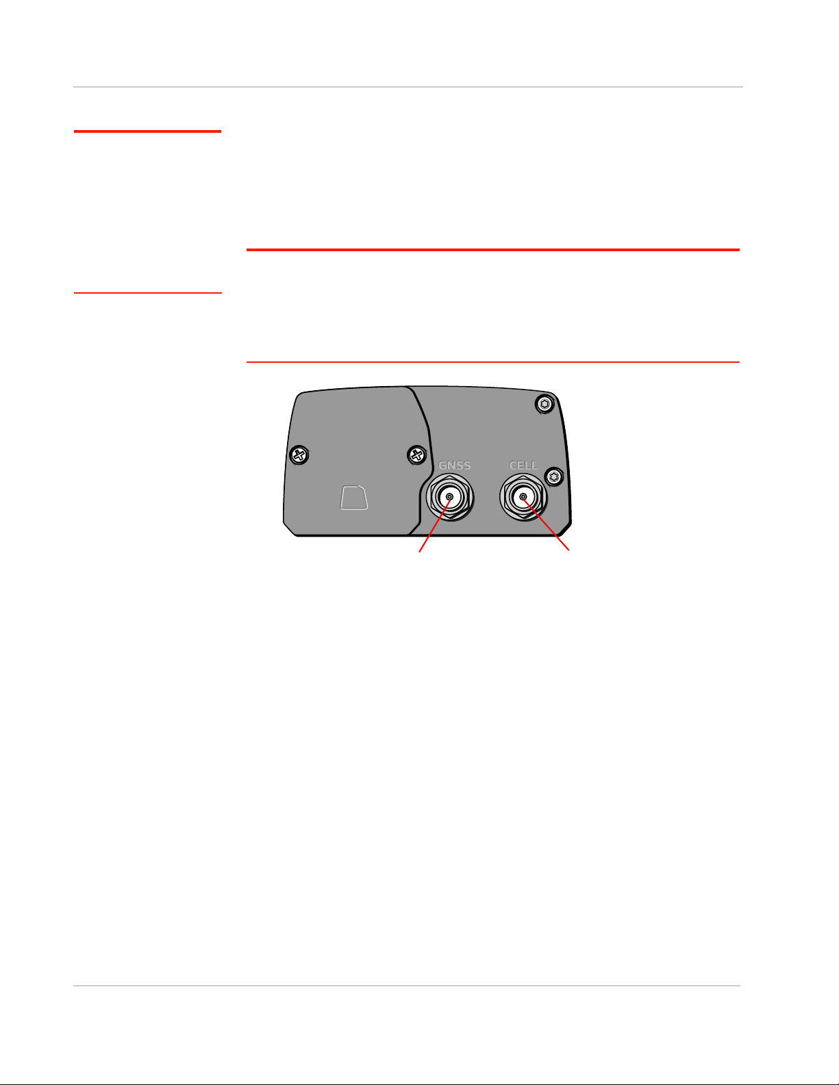
To install the antennas:
Cellular antenna connectorGNSS antenna connector
Installation and Startup
Note: Take extra care
when attaching the
antennas to the SMA
connectors. Finger tight
(approximately 0.6–0.8
Nm 5–7 in-lb.) is sufficient
and the max torque should
not go beyond 1.1 Nm
(10 in-lb.).
1. Connect the cellular antenna to the SMA cellular antenna connector.
Mount this antenna so there is at least 20 cm between the antenna and the
user or bystander.
2. If used, connect a GNSS antenna to the SMA GNSS antenna connector.
Mount the GNSS antenna where it has a good view of the sky (at least 90°).
Note: If the antennas are located away from the gateway, keep the cables as short as
possible to prevent the loss of antenna gain. Route the cables so that they are protected
from damage and will not be snagged or pulled on. There should be no binding or sharp
corners in the cable routing. Excess cabling should be bundled and tied off. Make sure the
cables are secured so their weight will not loosen the connectors from the gateway over
time.
Figure 2-12: Antenna Connectors
Rev 4 March 2019 19 41110030
Page 20
Sierra Wireless FX30 User Guide
USB Ethernet
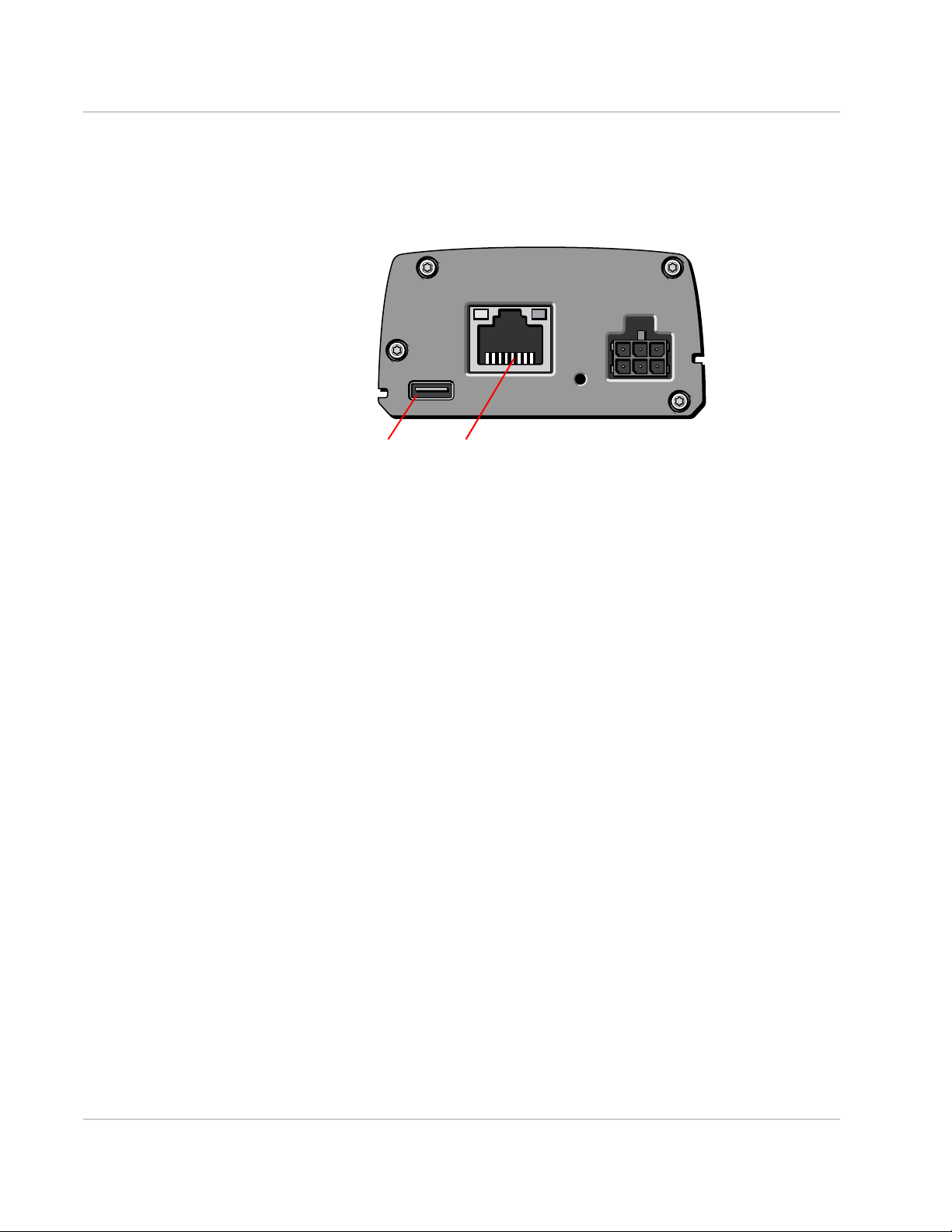
Step 4—Connect the Data Cables
The FX30 has two ports for connecting data cables:
• USB (Micro-B)
• Ethernet (RJ-45)— Use a Cat5 or greater Ethernet cable
Figure 2-13: Connectors for data cables
Cabling Concerns
Separate the antenna, data, and power cables from other wiring. Route the
cables away from sharp edges.
Cable Strain Relief
Sierra Wireless recommends using cable strain relief for installations in highvibration environments.
Place the cable strain relief within 200 mm (8 inches) of the FX30 to reduce the
mass of cable supported by the power connector under vibration. Ideally, the
strain relief mounting for the DC cable should be attached to the same object as
the gateway, so both the gateway and cable vibrate together. The strain relief
should be mounted such that it does not apply additional stress on the power
connector. The cable should not be taut and should not pull the power connector
at an angle.
Rev 4 March 2019 20 41110030
Page 21

Installation and Startup
123
456
Step 5—Connect the Power and I/O
The Sierra Wireless FX30 comes with a 1.5 meter (about 5 ft.) DC power cable.
For more information on the DC power cable, see page 58. You can also
purchase an optional AC adapter.
Warning: Electrical installations are potentially dangerous and should be performed by
personnel thoroughly trained in safe electrical wiring procedures.
The FX30 supports an operating voltage of 4.75–32 V.
Fusing
The Sierra Wireless DC power cable has a 3 A fuse installed in the cable. If that
cable is used, no additional fusing is required.
Power and I/O Connections
Table 2-1 describes the functions for the pins on the FX30 power connector. See
also I/O Configuration on page 25.
Figure 2-14: FX30 Power Connector
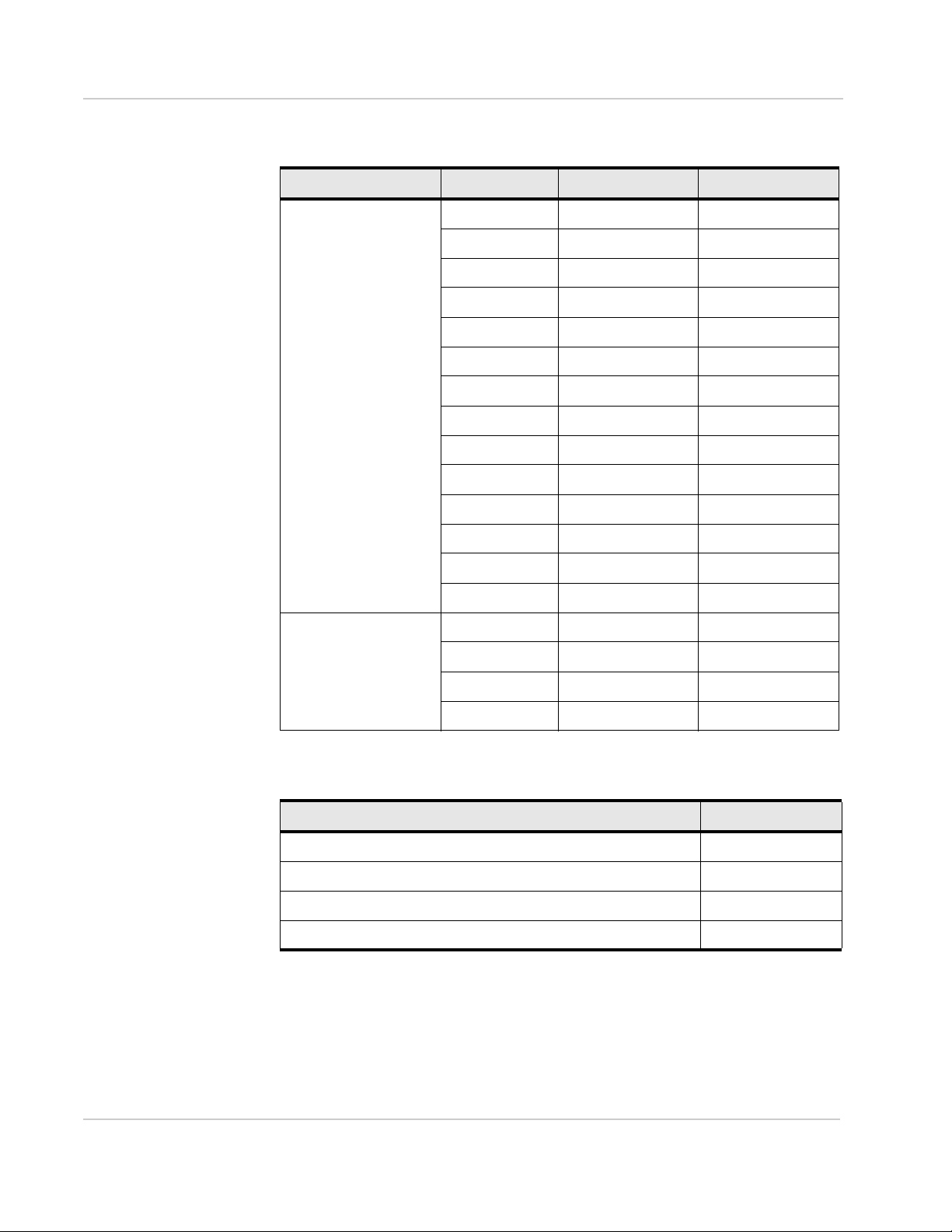
Table 2-1: Power Connector Pin and DC Cable Wires
Pin Function Associated
DC Cable
Wire Color
1 Power Red (20 AWG + Fuse)
2 Ground Black (20 AWG)
Description
Main power supply for device
Fuse: Slow-blow 3 A, 250 V (5 × 20 mm)
Note: If you want to turn the FX30 on/off using a
control line, Sierra Wireless strongly recommends that
you connect the on/off line to Pin 3 and apply
continuous power on Pin 1.
Main device ground
Rev 4 March 2019 21 41110030
Page 22

Sierra Wireless FX30 User Guide
Table 2-1: Power Connector Pin and DC Cable Wires
Pin Function Associated
DC Cable
Wire Color
3 On/Off Yell ow (28 AWG)
4 IO 1 Brown Digital input
5 IO 2 Green Digital input
6 IO 3 Orange Digital input
Description
On/Off: Control line to turn the gateway on and off. Pin
3 must be connected: either to the input power source
or to an on/off switch. The FX30 is off when this pin is
low, but you also have to option to monitor this pin
using GPIO 24, and holding the power on while a
Legato-designed application executes. For more
information, see OFF Mode on page 47.
Wake from low power modes
Internal pull-up control
Wake from low power modes
Internal pull-up control
Analog input
Internal pull-up control
Digital output
a
Note: See Table D-1, FX30 Hardware Feature to Linux Interface Mapping, on page 74
for the radio module GPIO and Linux interface mapping of pins 3 to 6.
a. For more information on power modes, see Power Modes on page 47.
Rev 4 March 2019 22 41110030
Page 23
Installation and Startup
Gateway
Power
On/ Off
Ground
DC power source
1
3
2
I/O1
I/O2
I/O3
FX30
DC power source
2 Ground
I/O 3
I/O 2
I/O 1
1 Power
3 On/Off
On/Off switch
DC power source
Gateway
Power
On/Off
Ground
1
3
2
I/O1
I/O2
I/O3
FX30
DC power source
2 Ground
I/O 3
I/O 2
I/O 1
1 Power
3 On/Off
On/Off switch
Wiring Diagrams
In the following diagrams, FX30 refers to either FX30 and FX30S.
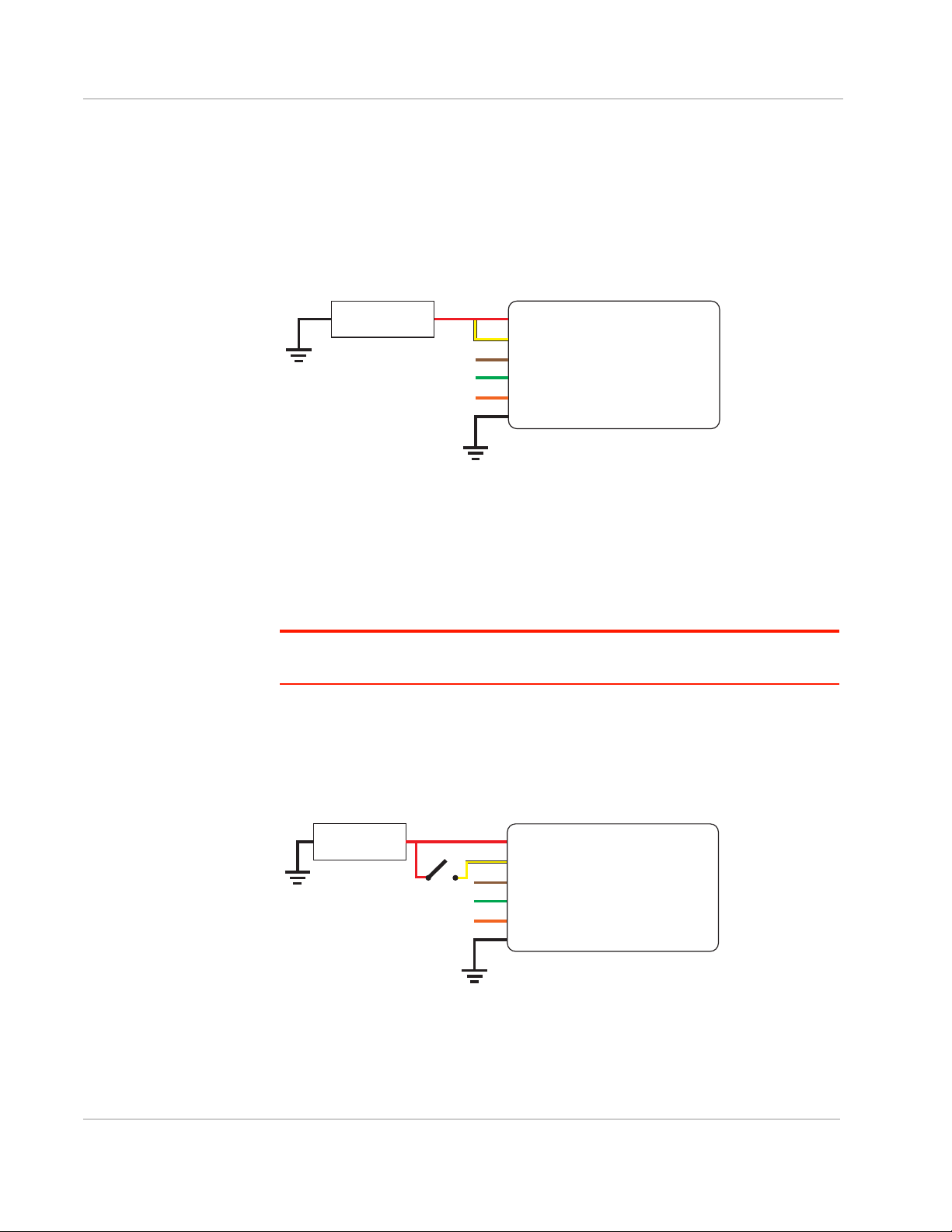
Always On Installation
For an Always On application, connect the wires as shown in Figure 2-15.
Figure 2-15: Always on installation
• Pin 1 (Power)—Use the red wire in the DC cable to connect Pin 1 to the
power source.
• Pin 2 (Ground)— Use the black wire in the DC cable to connect Pin 2 to
ground. See also Step 2— Mount and Ground the FX30 Chassis on page 12.
• Pin 3 (On/Off)— Connected to power
• Optional— I / O 1, I/ O 2, and I/O 3
Rev 4 March 2019 23 41110030
Note: See Table D-1, FX30 Hardware Feature to Linux Interface Mapping, on page 74 for
the radio module GPIO and Linux interface mapping of pin 3, I/O 1, I/O 2, and I/O 3.
On/Off Installation
For an On/Off application, connect the wires as shown in Figure 2-16 or
Figure 2-17.
Figure 2-16: On /Off Installation with switch
• Pin 1 (Power)—Use the red wire in the DC cable to connect Pin 1 to the
power source.
• Pin 2 (Ground)— Use the black wire in the DC cable to connect Pin 2 to
ground. See also Step 2— Mount and Ground the FX30 Chassis on page 12.
Page 24
Sierra Wireless FX30 User Guide
Gateway
Power
On/ Off
Ground
DC power source
1
3
2
I/O1
I/O2
I/O3
Sensor
NPN
FX30
DC power source
2 Ground
I/O 3
I/O 2
I/O 1
1 Power
3 On/Off
Sensor
DC power source
Gateway
Power
On/ Off
Ground
Motion sensor
1
3
2
I/O1
I/O2
I/O3
FX30
DC power source
2 Ground
I/O 3
I/O 2
I/O 1
1 Power
3 On/Off
Motion sensor
• Pin 3 (On/Off)— Connect to an on/off switch
Pin 3 must be connected.
• Optional— I / O 1, I/ O 2, and I/O 3
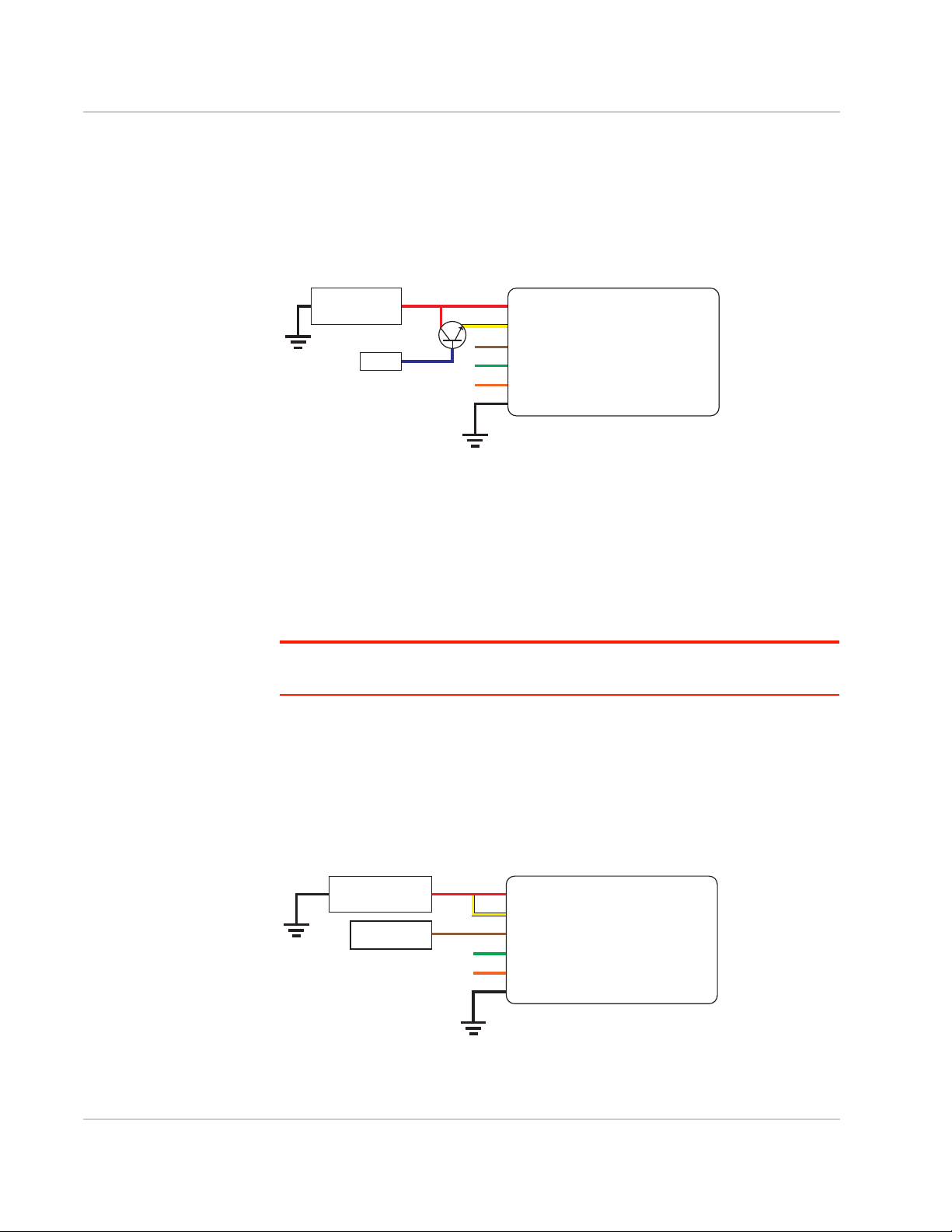
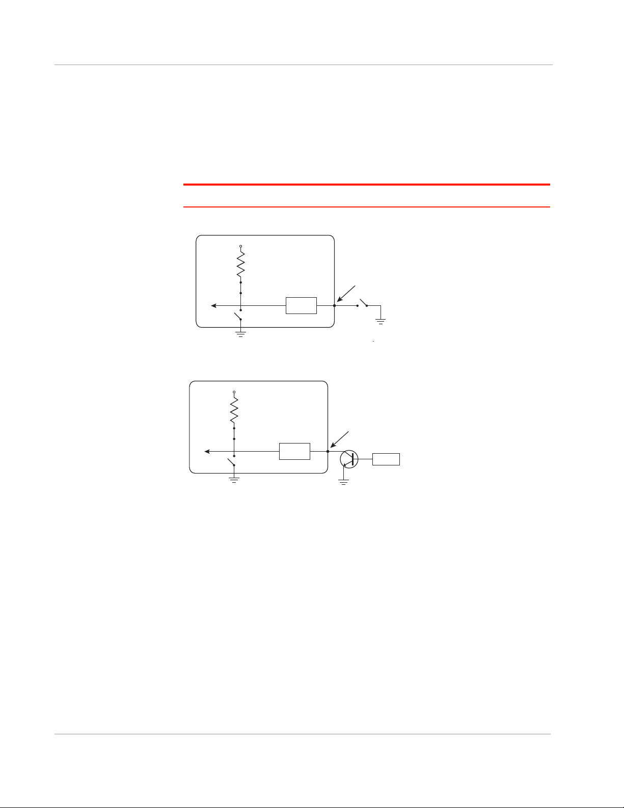
An On/Off installation may also use a sensor with an open-collector NPN or PNP
transistor. The transistor is the switch to turn the FX30 on or off, as shown in
Figure 2-17.
Figure 2-17: On/Off Installation (with sensor and NPN transistor switch)
• Pin 1 (Power)—Use the red wire in the DC cable to connect Pin 1 to the
power source and the collector pin of the transistor.
• Pin 2 (Ground)— Use the black wire in the DC cable to connect Pin 2 to
ground. See also Step 2— Mount and Ground the FX30 Chassis on page 12.
• Pin 3 (On/Off)— Connect to the emitter pin of the transistor
Pin 3 must be connected.
• Optional— I / O 1, I/ O 2, and I/O 3
Rev 4 March 2019 24 41110030
Note: See Table D-1, FX30 Hardware Feature to Linux Interface Mapping, on page 74 for
the radio module GPIO and Linux interface mapping of pin 3, I/O 1, I/O 2, and I/O 3.
Installation with I/O Input Triggered by Standby Mode
If you have an installation where you want to use the I/O to monitor an external
device such as a motion detector or gate sensor, refer to Figure 2-18. If desired,
you can use Legato to program the I/O line to wake the gateway from ultra low
power mode for a specific length of time.
Figure 2-18: Fixed Installation with I/O
Page 25

Installation and Startup
• Pin 1 (Power) —Use the red wire in the DC cable to connect Pin 1 to the
power source.
• Pin 2 (Ground)— Use the black wire in the DC cable to connect Pin 2 to
ground. See also Step 2— Mount and Ground the FX30 Chassis on page 12.
• Pin 3 (On/Off)—Connected to power
Pin 3 must be connected.
• I/O 1—configured for digital input
• Optional— I / O 2 and I/O 3
Note: See Table D-1, FX30 Hardware Feature to Linux Interface Mapping, on page 74 for
the GPIO and Linux interface mapping of pin 3, I/O 1, I/O 2, and I/O 3.
I/O Configuration
The FX30 power connector has three pins you can use for I/O configuration:
• I/O 1—Digital input only; allows wakeup from ultra low power mode
• I/O 2—Digital and analog input; allows wakeup from ultra low power mode
• I/O 3—Digital input and digital output
Note: See Table D-1, FX30 Hardware Feature to Linux Interface Mapping, on page 74 for
the GPIO and Linux interface mapping of the I/O pins.
Note: The IoT Expansion Card has four GPIO pins that you can program using Legato.
For details, refer to the IoT Expansion Card Design Specification.
I/ O Pins
You can use the I/O pins as:
• Digital inputs
(See Table 2-2 on page 26 and Figure 2-19 on page 26.)
• High side pull-ups/dry contact switch inputs
(See Figure 2-20 on page 27.)
• Analog inputs
(See Table 2-3 on page 28 and Figure 2-22 on page 28.)
• Low side current sinks
(See Figure 2-23 on page 28.)
• Digital outputs/ open drains
(See Table 2-4 on page 29 and Figure 2-24 on page 29.)
Note: The I/O pin functional ity is programmable in Legato applications.
Rev 4 March 2019 25 41110030
Page 26

Sierra Wireless FX30 User Guide
Gateway
Off
V
in
or 3.3 V*
Internal Pull-up
10 k
Resistor
FX30
Digital input
Internal pull-up
NſUHVLVWRU
Off
V
High ! 3.0 V
I/O 1, I/O 2, I/O 3
RQWKHSRZHUFRQQHFWRU
3URWHFWLRQ
FLUFXLWU\
Vin RU V
Digital Input
Digital input is available on I/ O 1, I/O 2, and I/O 3 on the power connector.
Note: To use I/O 3 as a digital Input, GPIO56 (that drives I/O 3 when used as a digital
output) must be low.
You can connect any of these pins to a digital input to detect the state of a digital
sensor or pulse counter.
Figure 2-19: Digital Input
Note: When using a digital input, the pull-up should be Off.
Table 2-2: Digital Input
Pull-up State Minimum Typica l Maximum Units
Off Low — — 1.0 V
High 3.0 — Vin V
Rev 4 March 2019 26 41110030
Page 27
Installation and Startup
Gateway
On
V
in
or 3.3 V*
Internal Pull-up
10 k Resistor
FX30
Internal pull-up
NſUHVLVWRU
On
I/O 1, I/O 2, I/O 3
RQWKHSRZHUFRQQHFWRU
3URWHFWLRQ
FLUFXLWU\
VLQRU V
2XWSXWRII
FX30
Internal pull-up
NſUHVLVWRU
On
I/O 1, I/O 2, I/O 3
RQWKHSRZHUFRQQHFWRU
6HQVRU
3URWHFWLRQ
FLUFXLWU\
VLQRU V
2XWSXWRII
High Side Pull-up / Dry Contact Switch Input
The three external I/O pins on the FX30 power connector have a high side pull-up
available. This high side pull-up can be driven low using a dry contact switch or
NPN/PNP transistor.
To use I/O 3 as a high side pull-up/switch input, GPIO56 (that drives I/O 3 when
used as a digital output) must be low.
Note: For this use case, the pull-up must be enabled.
Figure 2-20: High Side Pull-up / Dry Contact Switch Input
Figure 2-21: High Side Pull-up / Sensor and Transistor Input
Analog Input
Two analog inputs are available on the FX30. External I/O 2 on the power
connector maps to ADC1 on the WP module.
Table D-1, FX30 Hardware Feature to Linux Interface Mapping
The IoT interface analog pin maps to ADC0 on the WP module. For more
information, see Table 3-19, IoT Connector Interface on page 54.
You can connect either of these pins to an analog gauge. As an analog input
(voltage sensing pin), the gateway monitors voltage changes in small increments.
This allows you to monitor equipment that reports status as an analog voltage.
For more information, see
on page 74
.
Rev 4 March 2019 27 41110030
The pin detects inputs of 0 V–10 V. When used with a sensor to transform values
into voltages, the pin can monitor measurements like temperatures, pressures or
the volume of liquid in a container.
Page 28

Sierra Wireless FX30 User Guide
Gateway
Off (default)*
3.3V
10 k
Resistor
FX30
Solar panel or battery
Internal pull-up
NſUHVLVWRU
Off (default)
I/O 2 on the power
connector
3URWHFWLRQ
FLUFXLWU\
VLQor 3.3 V
+
_
5HVLVWRU
Gateway
Off
Vin
Protection
circuitry
V
in
Internal Pull-up
10 k
Resistor
FX30
Internal pull-up
NſUHVLVWRU
Off
3URWHFWLRQ
FLUFXLWU\
VLQ
I6LQN P$7\SLFDO
,2RQWKHSRZHU
FRQQHFWRU
VLQ
'LJLWDO
Output
([WHUQDOVROHQRLG
5HOD\FLUFXLW
Figure 2-22: Analog Input
Note: When using an analog input, the pul l-up should be Off.
Table 2-3: Analog Input
Pull-up Minimum Typical Maximum Units
Off Analog Input Range 0 — 10 V
Analog Input
— < 10 25 mV
Precision
Low Side Current Sink Output
Low side current sink output, for example to drive a relay, is only available using
I/O 3 on the power connector.
Figure 2-23: Low Side Current Sink
Note: When using low side current sink output, the pull-up should be Off.
The I/O can typically sink 400 mA, but this can vary depending on factors such as
temperature.
Rev 4 March 2019 28 41110030
Page 29

Installation and Startup
Gateway
Protection
circuitry
V
in
Off
Internal Pull-up
10 kResistor
Vcc
FX30
Internal pull-up
NſUHVLVWRU
Off
3URWHFWLRQ
FLUFXLWU\
VLQ
On/Off
,2RQWKHSRZHU
FRQQHFWRU
VFF
'LJLWDO
Output
External pull-up
Digital Output/Open Drain
Digital output/open drain is only available using I/ O 3 on the power connector.
Figure 2-24: Digital Output/Open Drain
Note: To provide voltage on the digital output, either use the internal pull-up or add an
external pull-up.
Table 2-4: Digital Output /Open Drain
Pull-up State Minimum Typ i c al Maximum Units Comments
Off Off Open Circuit — — — —
Active Low — — 0.5 V 5 mA, 5 V
Step 6—Check the FX30 Operation
1. On initial power up, the Power LED is red. When the processor boots up, the
LED turns amber (by default). The Power LED can be controlled by Legato
applications.
If the Power LED does not turn on, ensure that the:
· Power connector is plugged in and supplying voltage of 4.75 V or greater.
· On/Off (pin 3) is connected to the battery or power source. (See Step 5 —
Connect the Power and I/O on page 21 for details.)
Rev 4 March 2019 29 41110030
Page 30

Sierra Wireless FX30 User Guide
Power LEDUser LED
LED Behavior
Table 2-5: LED Behavior
LED Color / Pattern Description
Power
(Default Behavior)
Note: Based on three GPIOs. To define
the behavior of this LED, see Power LED
on page 75.
User
Note: Based on two GPIOs. To define the
behavior of this LED, see User LED on
page 75.
Note: You can write Legato applications to
define User LED behavior.
Ethernet LEDs
The connector has two LEDs that indicate speed and activity. When looking into
the connector:
• Right LED – Activity (blinking amber)
• Left LED – Connection speed (green indicates a 100 Mbps link, and off
indicates no cable is connected or a 10 Mbps link is detected).
Off No power or input voltage ≥ 32 VDC or ≤ 4.75 VDC
Solid Red Gateway is powered on, not attached to cellular
Solid Amber Attached to cellular network.
Possible colors:
network.
User-defined behavior
• Red
• Green
• Amber
Rev 4 March 2019 30 41110030
Page 31

Installation and Startup
Step 7—Use the FX30
You can use the FX30 as:
• A USB modem—You can use the FX30 as a USB bitpipe modem based on
the Qualcomm proprietary RMNET interface. This can be done through AT
commands using AT!SCACT to open and close the data session. For more
information and a detailed example, see Using the FX30 as a USB Modem on
page 62.
• An embedded cellular platform for IoT applications—Use AT commands,
Linux shell commands, or Legato to configure/program. See page 31.
Using the FX30 as an Embedded Platform for IoT Applications
To configure or program the FX30, you can use:
• AT Commands— see AT Commands Reference on page 65
• Linux Shell Commands— see Setup for Linux Shell Commands on page 32
• Legato Application Framework—Legato Application Framework on page 34
Setup for Windows
The following steps assume you have installed the USB drivers for WP Series
modules, available from http://source.sierrawireless.com/devices/fx-series/FX30/
(in the Software section under Windows drivers).
To set up the FX30 for use with Windows:
1. Power up the FX30 and connect it to a USB port on the computer.
2. The FX30 appears in Windows Device Manager as shown below.
• Under Modems, Sierra Wireless WWAN Modem appears. This is the
COM port for communicating with the modem via AT commands.
· To view the COM port number, right-click the modem name, select
Properties, and then select the Modem tab.
• Sierra Wireless LEGATO Ethlink ECM is the Ethernet network adapter
over USB, which allows you to SSH to the FX30.
• The Sierra Wireless DM Port is a serial port that allows firmware
updates via external tools.
• The Sierra Wireless NMEA Port is a serial port that outputs GPS information.
3. Open a terminal emulator program such as Tera Term.
Rev 4 March 2019 31 41110030
Page 32

Sierra Wireless FX30 User Guide
4. Connect to the AT command port. Set the terminal program com port to
match the port number you found for the Sierra Wireless WWAN Modem. You
should now be able to issue AT commands to the modem. If the connection
fails, check the serial port settings.
5. Use the terminal program to SSH to root@192.168.2.2 and establish a
secure shell connection, The first time you connect, you are prompted to
change your Linux root password.
Note: Ensure that you create an effective password that is longer than eight characters,
and uses special characters, numbers, and upper and lower case characters.
Useful AT Commands
The radio module for the FX30 is the Sierra Wireless AirPrime® WP8548,
WP7601-1, WP7603-1, WP7607-1, or WP7702. Useful radio module AT
commands include:
• Test AT command interface: AT should answer OK
• Get device information: ATI
• Get SIM status: AT+CPIN?
• Enter SIM PIN code: AT+CPIN=XXXX
• Configure APN: AT+CGDCONT=1,"IP","xxxxxx.xxx"
• Check APN configuration: AT+CGDCONT?
• Check signal quality: AT+CSQ
• Check network registration: AT+CREG?
• Check GPRS network registration: AT+CGREG?
• Check operator selected: AT+COPS?
• Check for PDP context status: AT+CGACT?
• Check for modem status: AT!GSTATUS?
• Open a LWM2M session to connect AirVantage: AT+WDSS=1,1
Warning: Do not use the AT+KSIMSEL command with the FX30. This command has the
capability of asserting GPIO6 when setting the <sim_slot> parameter to 1, causing the
FX30 to malfunction.
Setup for Linux Shell Commands
You can communicate with the FX30 using Legato shell commands. Before
beginning, install a Linux terminal application such as minicom or microcom.
To connect to the USB port on the Linux shell:
1. Connect the USB port on the FX30 to the computer.
In Linux, the AT command port and NMEA port are USB serial devices
located at /dev/ttyUSBx where x is the serial device number in the order it was
connected. X depends on the number of USB serial devices you have connected.
2. Connect an SSH client root@192.168.2.2
Rev 4 March 2019 32 41110030
Page 33

Installation and Startup
The first time you connect, you are prompted to change your Linux root password.
For more information, refer to the Legato shell documentation on legato.io
Useful Linux commands
Useful Linux commands include:
• Get device information: cm info
• Get SIM information: cm sim
• Get APN status: cm data
• Get modem status: cm radio
• Switch to AT mode: microcom -E /dev/ttyAT
<CTRL +x> to escape
• Read GPIO Value: cat /sys/class/gpio/gpioxx/value
• Set GPIO: echo 1 > /sys/class/gpio/gpioxx/value
• Clear GPIO: echo 0 > /sys/class/gpio/gpioxx/value
• Establish a data connection: cm data connect
• Check Legato application status: app status
For a complete list of Linux commands, see:
http://legato.io/legato-docs/latest/toolsTarget_cm.html
Here are some Linux shell command examples for GPIOs:
Table 2-6: Linux shell command examples
To... Use...
Turn on the green User LED echo 0 > /sys/class/gpio/gpio48/value
Turn off the green User LED echo 1 > /sys/class/gpio/gpio48/value
Read the push button state cat /sys/class/gpio/gpio7/value
Read the analog input value (in µV) cat /sys/class/hwmon/hwmon0/device/mpp_05
Rev 4 March 2019 33 41110030
Page 34

Sierra Wireless FX30 User Guide
Linux Interface Mapping
Table 2-7: FX30 Interface Mapping to the Linux Interface
GPIOs /sys/class/gpio/gpioxx
Ethernet (FX30 only) eth0
USB usb0
Serial (FX30S only) /dev/ttyHSL0
a. eth0 has a default IP address of 192.168.13.31
b. usb0 is a network interface and has a default IP address of 192.168.2.2
Linux Startup
The supported method of making changes to the Linux startup is to create a
Legato application. Changes or additions to the Linux scripts in /etc/rcS.d are
not supported by Sierra Wireless.
FX30 Interface Linux System
a
b
Reconfiguring the Firewall
For information about reconfiguring the firewall, see the Application Note FX30:
Network Interfaces and Firewall Rules (document number 41111930), available
on the Source.
Managing the I/O Interface
To manage the I/O interfaces such as digital and analog I/Os, LEDs, push button,
and hardware settings driven by GPIO, you can use:
• AT commands (see Managing the I/O Interface with AT Commands on
page 65)
• Linux shell commands (see FX30 Linux Interface and GPIO Mapping on
page 73)
• Legato Application Framework
· To use existing Legato tools, see docs.legato.io/latest/tools.html
· If you are interested in building your own Legato apps, see
docs.legato.io/latest/getStarted.html
Legato Application Framework
Before building custom applications for the FX30, you need to become familiar
with Legato. The best place to start is legato.io. Click the Build Apps icon. This
section contains:
• Concepts
· Overview—a high-level summary of Legato’s approach to application
development
· Develop Apps—the essentials for creating an app from scratch
Rev 4 March 2019 34 41110030
Page 35

Installation and Startup
· Definition Files— reusable external interfaces and internal content
· Sample Apps—sample apps for commonly-needed functions
• Tools—Information on Target, Host, and Build tools
• Security— For security reasons:
· You are prompted to change the Linux root password the first time you
attempt to log in to the Linux console.
· By default, all routes on the Ethernet and cellular interfaces are disabled. To
reconfigure the firewall to allow these connections, see Reconfiguring the
Firewall on page 34.
Other references:
• Download the Legato Reference Manual (PDF) from
http://source.sierrawireless.com/resources/legato/referencemanual
AirVantage IoT Platform
AirVantage IoT platform offers advanced services for device management,
connectivity management and for enabling device to cloud applications.
AirVantage Device Management services are available through a web-based
operations console providing an intuitive and customizable user interface to
configure, monitor, and manage your deployed FX30:
• Monitoring and Management
• Command and Control
• OTA Firmware Update
• Deployment Configuration
• Legato Application Lifecycle Management
Free and unlimited OTA Firmware Updates are offered with FX30.
To get started, call your Sierra Wireless reseller or visit https://airvantage.net/
Rev 4 March 2019 35 41110030
Page 36

Sierra Wireless FX30 User Guide
Factory reset button
Reset to Factory Default Settings
Warning: Resetting the gateway to the factory default settings will remove all customized
configuration settings in /etc and /data, including the root password.
Warning: Performing a factory reset could result in your FX30 no longer automatically
connecting to AVMS. If you perform a factory reset, please issue the AT command
AT+WDSC=3,60 to ensure your device checks in to AVMS every 60 minutes.
To reset the FX30 to the factory default settings:
1. Ensure that the Recovery Activation status is set to Enable. (See Factory
Reset AT Commands on page 71.)
2. Upon applying power, press and hold the reset button for about 10 seconds.
Figure 2-25: Factory reset button
Rev 4 March 2019 36 41110030
Page 37

3: Specifications
This chapter describes the FX30 gateway specifications.
Table 3-1: Specifications
3
Certification and
Interoperability
Environmental
Test i n g
Emissions /Immunity • CE (Including EMC Test case for vehicle installation EN301489)
• ACMA RCM
• FCC
• Industry Canada
Safety • CB Report IEC 60950-1
• UL Listed
Industry
Certification for
Vehicles
Environmental
Compliance
• E-Mark UN ECE Regulation No. 10 Rev. 5
• RoHS 2011/65/EU (RoHS 2)
• WEEE
• REACH
GSM/HSPA+
Certifications
Vibration
(operational)
Shock (operational) MIL-STD-810G, test method 516.6
SAE J1455 (Shock
and Vibration) for
heavy-duty vehicles
• PTCRB
• GCF
MIL-STD-810G, test method 514.6C
Category 4 CWV (Composite Wheeled Vehicle)
• Vibration: Section 4.10.4.2 Cab Mount
• Shock: Section 4.11.3.4 Operational Shock
• Electrical: 12 and 24 V systems
Section 4.13.1—12 and 24 V
Section 4.13.2—SAE J1113-11 Level IV
Temperature
(operational)
Temperature
(non-operational)
Thermal shock MIL-STD-810G, test method 503.5
Humidity
(operational)
IP rating IP30
Drop (nonoperational)
Electrostatic discharge (ESD) 8 KV contact discharge, 15 V air discharge
Mobile Network Operator Certification
(pending)
MIL-STD-810G, test methods 501.5, 502.5
(-30° to +75°C)
MIL-STD-810G, test methods 501.5, 502.5
(-40° to +85°C)
MIL-STD-810G, test method 517.5
95% RH over temperature range of +20°C to + 60°C
ISTA 2A 2001, test categories 1, 4, 5, and 6
• AT&T (planned)
Rev 4 March 2019 37 41110030
Page 38

Sierra Wireless FX30 User Guide
Table 3-1: Specifications (Continued)
Network
Technology
Host Interfaces Antenna connectors • Cellular
LTE, HSPA+
GSM /GPRS /EDGE
For lists of supported bands, see Radio Frequency Bands on
page 39.
• GNSS
USB • USB 2.0 micro-B connector complies with USB Version 2.0 for
high speed operation
• Sierra Wireless recommends you:
• Use a USB 2.0 cable
• Connect directly to your computer for best throughput.
Ethernet • 10/100 Base-T RJ-45 Ethernet
• Auto-crossover support
• Auto-negotiation, full- and half-duplex
• Not software configurable
IoT (Internet of
Things) Connector
SIM Card Interface • Mini-SIM (2FF) SIM card operated at 1.8 V/3.3 V.
Input / Output
For more information, see page 25.
Power Adapter Pins 6-Pin connector:
See Internet of Things (IoT) Expansion Card on page 51.
• Configurable I/O
• Wakeup on I/O, serial, or cellular events
• Power
• Ground
• On/Off
• I/O1
• I/O2
• I/O3
LEDs
See LED Behavior on page 30.
2 LEDs:
• Power
• User configurable
Mechanical Specifications
For mechanical drawings, dimensions, and
weight, see Mechanical Specifications on
page 45.
Screw Torque Settings • Mount screws
• Housing—The FX30 is made of ruggedized powder-coated
aluminum.
• RoHS2—The FX30 complies with the Restriction of Hazardous
Substances Directive 2011/65/EU (RoHS2). This directive
restricts the use of hazardous materials in the manufacture of
various types of electronic and electrical equipment.
1.1 N-m (10 in-lb)
• Antennas
Finger tight (5–7in-lb.) is sufficient and the max torque should
not go beyond 1.1 N-m (10 in-lb).
Operating Voltage 4.75 to 32 VDC
Rev 4 March 2019 38 41110030
Page 39

Table 3-1: Specifications (Continued)
Specifications
GNSS Technology Satellite channels
available
Support for
predicted orbits
Predicted orbit CEP50 accuracy
Constellations • GPS L1
GNSS Message
Protocol
Standalone Time to
First Fix (TTFF)
Sensitivity Standalone MS-based tracking sensitivity: -161 dBm
Radio Frequency Bands
Acquisition: 118
Simultaneous tracking: 40
Yes
5 meters
• Galileo E1
• GLONASS L1 FDMA
• BeiDou (WP7601-1/WP7603-1/WP7607/WP7702 only)
NMEA
• Hot start: 1 second
• Warm start: 29 seconds
• Cold start: 32 seconds
Cold start sensitivity: -145 dBm
MS-assisted GNSS acquisition sensitivity: -158 dBm
Table 3-2: FX30 Radio Module WP8548
Radio Technology Band Frequency (Tx) Frequency (Rx)
HSPA+ Band 1 1920–1980 MHz 2110– 2170 MHz
Band 2 1850 – 1910 MHz 1930 – 1990 MHz
Band 5 824– 849 MHz 869 –894 MHz
Band 6 830– 840 MHz 875 –885 MHz
Band 8 880– 915 MHz 925 –960 MHz
Band 19 830 – 845 MHz 875–890 MHz
GSM / GPRS/ EDGE Band 850 824 – 849 MHz 869–894 MHz
Band 900 880 – 915 MHz 925 – 960 MHz
Band 1800 1710–1785 MHz 1805–1880 MHz
Band 1900 1850–1910 MHz 1930–1990 MHz
Rev 4 March 2019 39 41110030
Page 40

Sierra Wireless FX30 User Guide
Table 3-3: FX30 Radio Module WP7601-1
Radio Technology Band Frequency (Tx) Frequency (Rx)
LTE Band 4 1710 – 1755 MHz 2110–2155 MHz
Table 3-4: FX30 Radio Module WP7603-1
Radio Technology Band Frequency (Tx) Frequency (Rx)
LTE Band 2 1850 – 1910 MHz 1930 – 1990 MHz
WCDMA Band 2 1850 – 1910 MHz 1930 – 1990 MHz
Band 13 777–787 MHz 746–756 MHz
Band 4 1710 – 1755 MHz 2110–2155 MHz
Band 5 824–849 MHz 869–894 MHz
Band 12 699–716 MHz 729 –746 MHz
Band 4 1710 – 1755 MHz 2110–2155 MHz
Band 5 824–849 MHz 869–894 MHz
Table 3-5: FX30 Radio Module WP7607-1
Radio Technology Band Frequency (Tx) Frequency (Rx)
LTE Band 1 1920 – 1980 MHz 2110– 2170 MHz
Band 3 1710 – 1785 MHz 1805–1880 MHz
Band 7 2500 – 2570 MHz 2620–2690 MHz
Band 8 880–915 MHz 925–960 MHz
Band 20 832–862 MHz 791–821 MHz
Band 28 703–748 MHz 758–803 MHz
UMTS Band 1 1920 – 1980 MHz 2110– 2170 MHz
Band 8 880–915 MHz 925–960 MHz
GMS/GPRS/EDGE 900 880– 915 MHz 925 – 960 MHz
1800 1710–1785 MHz 1805 –1880 MHz
Rev 4 March 2019 40 41110030
Page 41
Specifications
Table 3-6: FX30 Radio Module WP7702
Radio Technology Band Frequency (Tx) Frequency (Rx)
LTE Band 1 1920 – 1980 MHz 2110– 2170 MHz
Band 2 1850 – 1910 MHz 1930– 1990 MHz
Band 3 1710 – 1785 MHz 1805–1880 MHz
Band 4 1710 – 1755 MHz 2110–2155 MHz
Band 5 824–849 MHz 869–894 MHz
Band 8 880–915 MHz 925–960 MHz
Band 12 699–716 MHz 729 –746 MHz
Band 13 777–787 MHz 746–756 MHz
Band 17 704–716 MHz 734–746 MHz
Band 18 815–830 MHz 860–875 MHz
Band 19 830–845 MHz 875–890 MHz
Band 20 832–862 MHz 791–821 MHz
Band 26 814–849 MHz 859–894 MHz
Band 28 703–748 MHz 758–803 MHz
GSM / GPRS/ EDGE Band 850 824 – 849 MHz 869 – 894 MHz
Band 900 880 – 915 MHz 925 –960 MHz
Band 1800 1710 –1785 MHz 1805 – 1880 MHz
Band 1900 1850 –1910 MHz 1930 – 1990 MHz
Table 3-7: GNSS Bands Supported
Band Frequency
GPS L1 1575.42 MHz
GLONASS L1 FDMA 1602 MHz
Galileo E1 1575.42 MHz
BeiDou (WP7601-1/WP7603-1/WP7607-1/WP7702 only) 1561.098
Rev 4 March 2019 41 41110030
Page 42

Sierra Wireless FX30 User Guide
Radio Module Conducted Transmit Power
The following tables provide radio module conducted transmit power
specifications.
Table 3-8: Radio Module WP8548 Conducted Transmit Power
Band Conducted Tx
Power (dBm)
HSPA+
Band 1 (IMT 2100 12.2 kbps)
Band 2 (UMTS 1900 12.2 kbps)
Band 5 (UMTS 850 12.2 kbps)
Band 6 (UMTS 800 12.2 kbps)
Band 8 (UMTS 900 12.2 kbps)
Band 19 (UMTS 850 12.2 kbps)
GSM/GPRS/EDGE
GSM 850 +32±1 GMSK mode, connectorized
E-GSM 900 +32±1
DCS 1800 +29±1 GMSK mode, connectorized
PCS1900 +29±1
GSM 850 +26.5±1 8PSK mode, connectorized
E-GSM 900 +26.5±1
DCS 1800 +25.5±1 8PSK mode, connectorized
PCS1900 +25.5 ± 1
+23±1 Connectorized (Class 3)
Notes
(Class 4, 2 W; 33 dBm)
(Class 1, 1 W; 30 dBm)
(Class E2; 0.5 W; 27 dBm)
(Class E2; 0.4 W; 26 dBm)
Table 3-9: Radio Module WP7601-1 Conducted Transmit Power
Band Conducted Tx
Power (dBm)
LTE
Bands 4, 13 +23±1 Connectorized (Class 3)
Notes
Rev 4 March 2019 42 41110030
Page 43

Specifications
Table 3-10: Radio Module WP7603-1 Conducted Transmit Power
Band Conducted Tx
Power (dBm)
LTE
Bands 2, 4, 5, 12 +23±1 Connectorized (Class 3)
WCDMA
Band 2
Band 4
Band 5 (UMTS 850 12.2 kbps)
+23±1 Connectorized (Class 3)
Notes
Table 3-11: Radio Module WP7607-1 Conducted Transmit Power
Band Conducted Tx
Power (dBm)
LTE
Bands 1, 3, 7, 8, 20, 28 +23±1 Connectorized (Class 3)
WCDMA
Band 1
Band 8
GSM/GPRS/EDGE
+23±1 Connectorized (Class 3)
Notes
E-GSM 900 33+1/-2 GMSK mode, connectorized
(Class E4; 2 W; 33 dBm)
27±2.5 8PSK mode, connectorized
(Class E2; 0.5 W; 27 dBm)
DCS 1800 30+1/-2 GMSK mode, connectorized
26±2.5 8PSK mode, connectorized
(Class 1, 1 W; 30 dBm)
(Class E2; 0.4 W, 26 dBm)
Table 3-12: Radio Module WP7702 Conducted Transmit Power
Band Conducted
Tx Power (dBm)
LTE
Bands 1, 2, 3, 4, 5, 8, 12,
13, 17, 18, 19, 20, 26, 28
GSM/GPRS/EDGE
GSM 850 +32±1 GMSK mode (Class 4; 2 W, 33 dBm)
+23±1
+27±1 8PSK mode (Class E2; 0.5 W, 27 dBm)
Notes
Rev 4 March 2019 43 41110030
Page 44

Sierra Wireless FX30 User Guide
Table 3-12: Radio Module WP7702 Conducted Transmit Power (Continued)
Band Conducted
Tx Power (dBm)
E-GSM 900 +32±1 GMSK mode (Class 4; 2 W, 33 dBm)
+27±1 8PSK mode (Class E2; 0.5 W, 27 dBm)
DCS 1800 +29±1 GMSK mode (Class 1; 1 W, 30 dBm)
+26±1 8PSK mode (Class E2; 0.4 W, 26 dBm)
PCS 1900 +29±1 GMSK mode (Class 1; 1 W, 30 dBm)
+26±1 8PSK mode (Class E2; 0.4 W, 26 dBm)
Notes
Rev 4 March 2019 44 41110030
Page 45

Top view
Weight: 158 g (5.57 oz.)
Dimensions (l × w × h)
75 × 60 × 32 mm (excluding connectors)
82 × 60 × 32 mm (including connectors)
82 mm
75 mm
SIM card/ IoT card cover
GNSS antenna connector
Cellular antenna connector
USB
Ethernet (FX30 only.
Power connector
End views
60 mm
LEDs
FX30S has a serial port)
Specifications
Mechanical Specifications
Figure 3-1: FX30 Mechanical Specifications
Rev 4 March 2019 45 41110030
Page 46

Sierra Wireless FX30 User Guide
77.4 mm
12.7
37.1
62.7
73.7 mm
Mounting Bracket— top view
Mounting Bracket— side view
9 mm
25 mm
115 mm
0
16.1 mm
8.3 mm
Assembly
Compatibility bar
Rev 4 March 2019 46 41110030
Figure 3-2: Mounting Bracket Mechanical Specifications
Page 47

Specifications
Top View
Side View
End Views
Note: “Unit” refers to the gateway itself.
FX30 with Ethernet port shown
Figure 3-3: FX30 on mounting bracket
Power Modes
The FX30 is designed to handle extremely low power. It has three power modes:
• OFF Mode
• Ultra Low Power Mode on page 48
• Active Mode on page 48
OFF Mode
In Off mode the FX30 application processor, WWAN radio, and low power microcontroller are off. On/Off is controlled by the On/Off Pin 3/GPIO24 and Power
Hold/GPIO58.
If no Legato applications are in place for GPIO58 (power hold), the gateway is off
when Pin 3 is low and on when Pin 3 is high.
However, the power line from Pin 3 is also connected to GPIO58 (power hold).
GPIO58 is low by default. If either Pin 3 or GPIO58 is high, the gateway is on.
GPIO24 monitors Pin 3. (See Figure 3-4 on page 48.) This gives you the option to
design an application that detects when Pin 3 goes low, and holds the power on
temporarily to complete the desired actions prior to the gateway turning off, for
example, a graceful shutdown process or a last-gasp type feature.
Rev 4 March 2019 47 41110030
Page 48

Sierra Wireless FX30 User Guide
Gateway
Internal power circuits
Processor
GPIO24
(monitors Pin 3)
GPIO58
(power hold)
Pin 3
Pin 1
(Power)
(On/Off)
If GPIO24 is low (0), Pin 3 is “On”.
If GPIO24 is high (1), Pin 3 is “Off”.
Enable
Power input
Figure 3-4: FX30 On/Off functionality
Typical wake-up time before network attach is 15 seconds.
Ultra Low Power Mode
In Ultra Low Power Mode (ULPM), the FX30 application processor and WWAN
radio are off.
The low power micro-controller monitors the wakeup triggers which are:
• Timer (The timer wakeup must be configured prior to the gateway entering
ULPM.) You can use the Legato Timer API or the Legato Power Management
tool (pmtool) command to configure wakeup from ULPM.
• Digital Inputs IO 1 and IO 2 (IO wakeup must be configured prior to the
gateway entering ULPM.) You can use the Legato Power API or pmtool
command to configure wakeup from ULPM.
Note: The external digital IO1 and IO2 are connected to GPIO2 and GPIO21 on the WP
module as standard digital inputs and are also routed to GPIO36 and GPIO38 to wake up
from ULPM. See Table D-2 on page 76.
FX30 can be put into ULPM using the “pmtool shutdown” Legato command or the
Ultra Low Power Mode Legato API.
Typical wake-up time before network attach is 15 seconds.
Active Mode
In Active mode the FX30 application processor is running and the modem is
operating in one of the following modes:
Rev 4 March 2019 48 41110030
• Full function—The application processor is fully functional and the WWAN
radio is on; the GNSS radio can be turned on/off.
• Idle—The application processor is fully functional and the WWAN radio is on.
The module is registered on the network, but there is no active connection;
the GNSS radio can be turned on/off.
Page 49

• Airplane mode—The application processor is fully functional and the WWAN
radio is off; the GNSS radio can be turned on/off. By default the GNSS radio
is on.
Depending on the application, you can lower power consumption by disabling the
Ethernet interface and GPS bias using GPIO52 and GPIO55 respectively. (See
Table D-1 on page 74.)
Power Consumption
Table 3-13: Power Consumption — Active Mode FX30 3G (WP8548)
Mode Conditions Vo l t a g e Max continuous Burst
V mA mW mA mW
Specifications
Active Idle
Active Full
Function
WCDMA
Active Full
Function GSM
USB and
plugged in
Max Tx power (+23 dBm)
USB 70 Mbps
Ethernet 55 Mbps
Max Tx power (+31 dBm)
USB 70 Mbps
Ethernet 55 Mbps
Ethernet
cables are
24 40 960
12 74 888
4.5 180 810 208 936
24 138 3312 145 3480
12 265 3180 270 3240
5 604 3020 645 3225
24 110 2640 308 7392
12 212 2544 600 7200
5 550 2750 1670 8350
Table 3-14: Power Consumption — Active Mode FX30 Cat-1 (WP7601-1)
Mode Conditions Vo l t a g e Max continuous Burst
V mA mW mA mW
Active Idle
USB and
plugged in
Ethernet
cables are
24 56 1364 236 5672
12 114 1371 532 6382
4.5 254 1141 1339 6027
Active Full
Function LTE
Max Tx power (+33 dBm)
USB 110 Mbps
Ethernet 94 Mbps
24 212 5101 317 7611
12 397 4767 719 8625
4.5 1048 4716 1804 8118
Rev 4 March 2019 49 41110030
Page 50

Sierra Wireless FX30 User Guide
Table 3-15: Power Consumption — Active Mode FX30 Cat-1 (WP7603-1)
Mode Conditions Vo l t a g e Max continuous Burst
V mA mW mA mW
Active Idle
Active Full
Function LTE
Active Full
Function
HSDPA
USB and
plugged in
Max Tx power (+33 dBm)
USB 110 Mbps
Ethernet 94 Mbps
Max Tx power (+33 dBm)
USB 110 Mbps
Ethernet 94 Mbps
Ethernet
cables are
24 56 1364 236 5672
12 114 1371 532 6382
4.5 254 1141 1339 6027
24 226 5420 317 7611
12 419 5034 719 8625
4.5 1113 5007 1804 8118
24 195 4686 306 7347
12 363 4366 693 8327
4.5 954 4292 1741 7837
Table 3-16: Power Consumption — Active Mode FX30 Cat-1 (WP7607-1)
Mode Conditions Vo l t a g e Max continuous Burst
V mA mW mA mW
Active Idle
USB and
plugged in
Ethernet
cables are
24 94 2254 TBD
12 183 2195 TBD
4.5 439 1977 TBD
Active Full
Function LTE
Max Tx power (-18 dBm)
USB 103 Mbps
Ethernet 85 Mbps
24 112 2680 TBD
12 209 2511 TBD
4.5 542 2441 TBD
Table 3-17: Power Consumption — Active Mode FX30 Cat-M (WP7702)
Mode Conditions Vo l t a g e Max continuous Burst
V mA mW mA mW
Active Idle
USB and
plugged in
Ethernet
cables are
24 56 1364 236 5672
12 114 1371 532 6382
4.5 254 1141 1339 6027
Rev 4 March 2019 50 41110030
Page 51

Table 3-17: Power Consumption — Active Mode FX30 Cat-M (WP7702)
Mode Conditions Vo l t a g e Max continuous Burst
V mA mW mA mW
Specifications
Active Full
Function GSM
Active Full
Function LTE
Max Tx power (+33 dBm)
USB 110 Mbps
Ethernet 94 Mbps
Max Tx power (+33 dBm)
USB 110 Mbps
Ethernet 94 Mbps
24 195 4686 274 6584
12 357 4282 622 7461
4.5 918 4133 1560 7022
24 174 4184 290 6971
12 319 3824 658 7900
4.5 820 3690 1652 7435
Table 3-18: Power Consumption — Off and Ultra Low Power Modes
Mode Conditions Volta g e Maximum continuous
V µA µW
Off On / Off is set to Off 24 13 312
12 33 396
4 67 268
Ultra Low Power Triggering timer 24 165 3960
12 170 2040
4 348 1392
Internet of Things (IoT) Expansion Card
The FX30 is compatible with single slot, category 1 (14 mm maximum), power
category 1 and 2 IoT Expansion cards. The IoT connector has 38 pins and
supports the following interfaces:
• 1 × ADC
• 4 × GPIO
• 1 × I2C
• 1 × PCM
• 1 × SPI
• 1 × UART
• 1 × USB
• 1 × SDIO
Rev 4 March 2019 51 41110030
Page 52

Sierra Wireless FX30 User Guide
XSEC0001 XSEC0001
Front end plate
Front end plate
Front PCA edge
Front end plate to front PCA edge
Section XSEC0001 - XSEC0001
1.89 mm
For IoT Expansion Card Developers
When developing an IoT Expansion card to use with the FX30, be aware that the
distance between the front SMA end plate and PCA front edge is 1.89 mm.
Figure 3-5: IoT Expansion Card Alignment
Rev 4 March 2019 52 41110030
Page 53

Specifications
CN200
CONN_38P_EDGE_IOT
25
2019
18
17
16
24
23
22
21
15
14
13
12
11
30
28
27
26
29
5
4
3
2
138
37
36
35
10
9
8
7
6
34
33
32
31
VCC_1V8
VCC_3V3
VCC_5V0
n_CARD_DETECT
GPIO_2
I2C_SCL
I2C_SDA
USB_D-
USB_D+
SDIO_CMD
SDIO_CLK
SDIO_DAT1
SDIO_DAT2
SDIO_DAT0
SDIO_DAT3/CD
PCM_DIN
PCM_DOUT
PCM_SYNC
PCM_CLK
GPIO_4
GPIO_3
UART_TXD
UART_RXD
UART_CTS
UART_RTS GPIO_1
n_RESET
SPI_CLK
SPI_MISO
SPI_MOSI
SPI_SS/MRDY
ADC0
PPS
Pin-out Information
For complete pin-out information, refer to the IoT Expansion Card Design
Specification.
Figure 3-6: IoT Expansion Card Pin Configuration—IoT Expansion Card View
Rev 4 March 2019 53 41110030
Page 54

Sierra Wireless FX30 User Guide
IoT Connector Interface
Table 3-19: IoT Connector Interface
IoT Connector
Signal
FX30 Hardware
Peripheral
Linux Interface
GPIO1 GPIO42 /sys/class/gpio/gpio42
GPIO2 GPIO33 /sys/class/gpio/gpio33
GPIO3 GPIO13 /sys/class/gpio/gpio13
GPIO4 GPIO8 /sys/class/gpio/gpio8
Iot_DETECT GPIO25 /sys/class/gpio/gpio25
USB Hub on HSIC WP interface,
/dev/ttyUSB0
mounted on ttyUSB0
SDIO SDIO /dev/mmcblk0
UART UART2 /dev/ttyHSL1
SPI SPI1 /dev/spidev1.0
a
ADC ADC0 /sys/class/hwmon0/device/mmp_01
(in uV units) (WP85)
/sys/devices/qpnp-vadc-8/mpp2_div1
(WP76/77)
PCM PCM /proc/asound and /dev/snd
I2C I2C1 /dev/i2c-0 (WP85)
/dev/i2c-4 (WP76/77)
a. For SPI, 3G version R12.x supports the /dev/sierra_spi device.
3G versions R13.1 and R14 support the /dev/spidev device; however, there is a known issue.
Please follow the Legato guide: https://docs.legato.io/17_08/howToSPI.html
Cat1 version R10.1 supports the /dev/spidev device; however, the spisvc kernel module must
be manually loaded:
See the Customer Release Notes for more details.
CatM version R9.1 supports the /dev/spidev device; however, the spisvc kernel module is not
present and needs to be manually copied to the device.
insmod /mnt/legato/system/modules/spisvc.ko
Note: If you develop an IOT card and use the UART in a hardware loop-back mode by
connecting the transmit and receive signals, do not configure UART2 in Linux Console
mode (AT!MAPUART=16,2).
Rev 4 March 2019 54 41110030
Page 55

4: Regulatory Information
Important Information for North American Users
Warning: This equipment has been tested and found to comply with the limits for a Class A
digital device, pursuant to part 15 of the FCC Rules. These limits are designed to provide
reasonable protection against harmful interference when the equipment is operated in a
commercial environment. This equipment generates, uses, and can radiate radio frequency
energy and, if not installed and used in accordance with the instruction manual, may cause
harmful interference to radio communications. Operation of this equipment in a residential area
is likely to cause harmful interference, in which case the user will be required to correct the
interference at his own expense. Changes or modifications to this device not expressly
approved by Sierra Wireless could void the user's authority to operate this equipment.
RF Exposure
In accordance with FCC/IC requirements of human exposure to radio frequency
fields, the radiating element shall be installed such that a minimum separation
distance of 20 cm should be maintained between the antenna and the user's body.
4
Warning: This product is only to be installed by qualified personnel.
To comply with FCC/IC regulations limiting both maximum RF output power and
human exposure to RF radiation, the maximum antenna gain must not exceed the
specifications listed below for the device used.
Maximum Antenna Gain
The antenna gain must not exceed the limits and configurations shown in the
following tables:
Device Frequency Band FCC ID/IC Number
N7NWP8/2417C-WP8
Maximum Antenna Gain (dBi)
Sierra Wireless FX30 2 3
5 4
GPRS/EDGE 850 4
GPRS/EDGE 1900 3
Rev 4 March 2019 55 41110030
Page 56

Sierra Wireless FX30 User Guide
Sierra Wireless FX30 4 6
Sierra Wireless FX30 2 6
Device Frequency Band FCC ID/IC Number
N7NWP76A/2417C-WP76A
Maximum Antenna Gain (dBi)
13 6
Device Frequency Band FCC ID/IC Number
N7NWP76C/2417C-WP76C
Maximum Antenna Gain (dBi)
4 6
5 6
12 6
WCDMA 2 6
WCDMA 4 6
WCDMA 5 6
FCC ID/IC Number
N7NWP77B 2417C-WP77B
Maximum antenna gain (dBi)
Device Frequency Band
Standalone Collocated
AirLink FX30 2 9 8
b
4
6 6
5 7 6
12 6 6
13 6 6
c
17
6 6
26 7 6
GSM 850 4 3
a
PCS 1900 3 3
a. Antenna gain limit when module collocated with Wi-Fi/Wimax/BT radios
b. B4—CAT-M1 only
c. B17 — CAT-NB1 only
Rev 4 March 2019 56 41110030
Page 57

Regulatory Information
EU
Sierra Wireless hereby declares the Sierra Wireless FX30 device is in compliance
with the essential requirements and other relevant provisions of Directive 1999/5/
EC.
The FX30 displays the CE mark.
Warning: Changes or modifications to this device not expressly approved by Sierra
Wireless could void the user's authority to operate this equipment.
Warning: This product is only to be installed by qualified personnel.
Declaration of Conformity
The Declaration of Conformity made under Directive 1999/5/EC is available for
viewing at source.sierrawireless.com.
WEEE Notice
If you purchased your Sierra Wireless FX30 in Europe, please return it to your
dealer or supplier at the end of its life. WEEE products may be recognized by their
wheeled bin label on the product label.
Rev 4 March 2019 57 41110030
Page 58

A: Accessories
123
4
Power connector (end view) Power connector housing (side view)Pin Wire color
1
2
3
4
Red
Black
Orange
Green
3048 mm (10 ft.) core cable
Power connector housing
Fuse holder
Male housing
Female crimp terminals
5
6
5
6
Ye ll ow
Brown
DC Power Cable (Black Connector)
Table A-1: DC Power Cable
DC Power Cable
Part Number 2001013
Product Release 2016
Components:
1 UL2464 20 AWG × 6 core cable
6 × Molex Micro-Fit 3.0™ series female crimp connectors (part number 43030-0001)
1 × Molex Micro-Fit 3.0™ receptacle housing, male, 2×3P Ph: 3.0 mm housing,
250 V, 5 A max, PA65 black UL94V-O (part number 43025-0600)
A
Figure A-1: DC Cable Specifications
Rev 4 March 2019 58 41110030
Page 59

Accessories
AC Power Adapter (Black Connector)
Table A-2: AC Power Adapter
AC Power Adapter
Part Number TBC
Product Release 2016
AC Power Adapter Input
Table A-3: Input Specifications
Minimum Typical Maximum
Input
Input Voltage 90 VAC 100 – 240 VAC 264 VAC
Input Frequency 47 Hz 50/ 60 Hz 63 Hz
Note: Input voltage range is 90–264 VAC.
Maximum input current is 500 mA at 100–240 VAC.
Inrush current will not exceed 75 A at 100–240 VAC input and maximum load from a
cold start at 25°C.
AC Power Adapter
Table A-4: AC Power Adapter Output Specifications
Minimum Typical Maximum Test conditions
Output Voltage — 11.4 VDC 12.0 VDC 12.6 VDC 0 ~ 1.5 A loading
Output
Environmental Specifications
Table A-5: AC Power Adapter Environmental Specifications
Operating
Operating Temperature 0°C ~ 40°C (operates normally)
Relative Humidity 10% ~ 90%
Altitude Sea level to 2,000 meters
Vibration 1.0 mm, 10– 55 Hz, 15 minutes per cycle for each axis (X, Y, Z)
Non-operating
Storage Temperature -30°C ~ 70°C
Rev 4 March 2019 59 41110030
Page 60

Sierra Wireless FX30 User Guide
Table A-5: AC Power Adapter Environmental Specifications (Continued)
Relative Humidity 10% ~ 90%
Vibration and Shock MIL-STD-810D, method 514
Reliability and Quality Control
AC Power Adapter MTBF
When the power supply is operating within the limits of this specification, the
MTBF is at least 200,000 hours at 25°C (MIL-HDBK-217F).
Safety Standards
The power supply is certified with the following international regulatory standards:
Table A-6: AC Power Adapter Safety standards
Regulatory Agency Country or Region Certified Standard
UL USA Approved UL60950-1
GS Europe Approved EN60950-1
CE Europe Approved EN60950-1
SAA Australia Approved AS/NZS 60950
CCC China Approved GB4943
CUL Canada Approved CSA C22.2 NO.60950-1
EMC Standards
The power supply meets the radiated and conducted emission requirements for
EN55022, FCC Part 15, Class B, GB9254.
Hazardous Substances
• EU Directive 2011/65/EU “RoHS”
• EU Directive 2012/19/EU “WEEE”
• REACH
Rev 4 March 2019 60 41110030
Page 61

Accessories
Energy Efficiency
The AC adapter complies with International Efficiency Levels, as shown in
Table A-7.
Table A-7: AC Adapter Energy Efficiency
Supplied Input No-load Power
Consumption
115 VAC, 60 Hz Less than 0.1 W Greater than 85% VI
230 VAC, 50 Hz Less than 0.3 W Greater than 80.4% V
Average Active
Mode Efficiency
International
Efficiency Level
Rev 4 March 2019 61 41110030
Page 62

B: Using the FX30 as a USB Modem
The following instructions provide examples based on Telus service. Substitute the
name of your mobile network operator (MNO). Key values and parameters are bolded
for emphasis in the examples.
For detailed information about the AT commands used, refer to AirPrime WPx5xx AT
Command Reference (4118047) available at source.sierrawireless.com.
To use the FX30 as a USB modem:
1. Ensure that your computer is set up to issue AT commands to the FX30. (See
Setup for Windows on page 31.)
2. Connect the radio to the network:
a. If you have not already done so, install the SIM card. (See Step 1—Insert the
SIM Card and Optional IoT Card on page 11.)
b. Set the MNO’s APN using the AT+CGDCONT command. (Most MNOs use
Profile number 1. To confirm, check with your MNO.)
AT+CGDCONT=1,"IPV4V6","isp.telus.com"
c. Check that the profile is correctly set:
AT+CGDCONT?
+CGDCONT: 1,"IPV4V6","isp.telus.com","0.0.0.0",0,0
d. Check that the radio is attached and registered on the network.
AT!GSTATUS?
!GSTATUS:
Current Time: 5699 Temperature: 31|
Bootup Time: 0 Mode: ONLINE
System mode: WCDMA PS state: Attached
WCDMA band: WCDMA 1900
WCDMA channel: 662
GMM (PS) state:REGISTERED NORMAL SERVICE
MM (CS) state: IDLE NORMAL SERVICE
B
WCDMA L1 State:L1M_PCH_SLEEP LAC: 2B5D (11101)
RRC State: DISCONNECTED UTRAN Cell ID: 0454
761C (1108 30236)
RxM RSSI C0: -80 RxD RSSI C0: -106
RxM RSSI C1: -106 RxD RSSI C1: -106
IMS Reg State: UNKNOWN IMS Mode: Not Support
IMS Srv State: UNKNOWN SMS,UNKNOWN VoIP
OK
3. Activate the PDP context:
a. Use the Profile number prepared in steps 2b and 2c above.
AT!SCACT=1,1
b. Check the profile is active:
AT!SCACT?
!SCACT: 1,1
Rev 4 March 2019 62 41110030
Page 63

Using the FX30 as a USB Modem
c. Confirm the PDP context is active.
ACTIVE data session:
at!gstatus?
!GSTATUS:
Current Time: 7209 Temperature: 33
Bootup Time: 0 Mode: ONLINE
System mode: WCDMA PS state: Attached
WCDMA band: WCDMA 1900
WCDMA channel: 662
GMM (PS) state:REGISTERED NORMAL SERVICE
MM (CS) state: IDLE NORMAL SERVICE
WCDMA L1 State:L1M_DCH LAC: 2B5D
(11101)
RRC State: CELL_DCH UTRAN Cell ID: 0454
761C (1108 30236)
RxM RSSI C0: -91 RxD RSSI C0: -106
RxM RSSI C1: -84 RxD RSSI C1: -106
IMS Reg State: UNKNOWN IMS Mode: Not Support
IMS Srv State: UNKNOWN SMS,UNKNOWN VoIP
OK
The RMNET interface on the host computer should now become active, and
receive an IP address. Data can now flow from the host computer to the radio
network.
4. Deactivate the PDP context:
a. Deactivate the active context
AT!SCACT=0,1
b. Check the profile is deactivated
AT!SCACT?
!SCACT: 1,0
c. Confirm the PDP context is de-activated.
DE-ACTIVATED data session:
at!gstatus?
!GSTATUS:
Current Time: 7227 Temperature: 33
Bootup Time: 0 Mode: ONLINE
System mode: WCDMA PS state: Attached
WCDMA band: WCDMA 1900
WCDMA channel: 662
GMM (PS) state:REGISTERED NORMAL SERVICE
MM (CS) state: IDLE NORMAL SERVICE
WCDMA L1 State:L1M_PCH_SLEEP LAC: 2B5D
(11101)
RRC State: DISCONNECTED UTRAN Cell ID:
0454 761C (1108 30236)
RxM RSSI C0: -91 RxD RSSI C0: -106
RxM RSSI C1: -106 RxD RSSI C1: -106
Rev 4 March 2019 63 41110030
Page 64

Sierra Wireless FX30 User Guide
The RMNET interface on the host computer should now be de-activated. The IP
address should no longer be assigned, and data should no longer be flowing.
IMS Reg State: UNKNOWN IMS Mode: Not Support
IMS Srv State: UNKNOWN SMS,UNKNOWN VoIP
OK
Rev 4 March 2019 64 41110030
Page 65

C: AT Commands Reference
This appendix documents the AT commands that are specific to the FX30. For a
complete list of AT Commands for the radio modules available for the FX30, refer to
the WP8548/WP75xx/WP76xx/WP77xx AT Command Reference (document number
4118047).
In addition, the AT Commands in Table C-2 are specific to the FX30.
Note: Parameters in angled brackets < > are mandatory. Parameters in square brackets [ ] are
optional.
Managing the I/O Interface with AT Commands
See AT!FWD?GPIO and AT!FWD=GPIO documentation in Table C-1, and I/O
mapping in Table D-1 on page 74.
Because some FX30 GPIOs are driven by an I/O expander, do not use standard
AT+WIOR/WIOW AT commands for the FX30.
Warning: Most FX30 GPIOs are preconfigured. D o not use the AT+WIOCFG command!
Using this command could make the FX30 inoperable.
C
Here are some AT command examples for GPIOs:
Table C-1: AT command examples
To... Use...
Turn on the green User LED AT!FWD=GPIO,48,0
Turn off the green User LED AT!FWD=GPIO,48,1
Read the push button state AT!FWD?GPIO,7
Read the analog input value (in mV) AT!MADC?5
Rev 4 March 2019 65 41110030
Page 66

Sierra Wireless FX30 User Guide
Table C-2: FX30 AT Commands
Command Description
GPIO AT Commands
AT!FWD? G P I O
Reads the current value of any input
or output GPIO.
AT!FWD= G P I O
Sets the value of any configured
output GPIO.
To Query:
AT!FWD?GPIO,<GPIO #>
where <GPIO #> is any available GPIO, i.e.: 2,7,8,13,21–25,32–58
Returned values are:
• 0 (low) or 1 (high)
• ERROR if invalid GPIO#
Example:
AT!FWD?GPIO,2
1
OK
AT!FWD?GPIO,10
ERROR
To s e t:
AT!FWD=GPIO,<GPIO #>,<value>
where:
• <GPIO #> is any GPIO set as an output. i.e.: 32,43–58
8,13,25,33,42 only valid if set as output
• <value> is either 0 (low) or 1 (high)
Returned values are:
• OK (if GPIO is set as requested)
• ERROR (if invalid GPIO # or value)
Example:
AT!FWD=GPIO,43,1
OK
AT!FWD=GPIO,2,1
ERROR
Rev 4 March 2019 66 41110030
Page 67

Table C-2: FX30 AT Commands
Command Description
AT Commands Reference
AT!FWD?GPIOCFG
Displays the direction and pull settings
for exported GPIOs, as read from
sysfs.
If the GPIO is not exported, this
command reports “NOT SET”. It does
not export the GPIO.
AT!FWD=GPIOCFG
Configures the direction and optionally
the pull setting for any configurable
GPIO.
This command exports a GPIO if it is
not currently exported.
Setting is runtime configurable only—
this setting is NOT persistent through
reboot.
To query:
AT!FWD?GPIOCFG,<GPIO #>
where <GPIO #> is any available GPIO, i.e. 2,7,8,13,21–25,32–58
Returned values are:
• NOT SET (if GPIO has not been exported)
• DIRECTION: <IN|OUT>
• PULL: <UP|DOWN> (if GPIO has been exported)
• ERROR (if invalid GPIO #)
Example:
AT!FWD?GPIOCFG,2
DIRECTION: IN
PULL: UP
OK
AT!FWD?GPIOCFG,8
NOT SET
OK
AT!FWD?GPIOCFG,10
ERROR
To s e t:
AT!FWD=GPIOCFG,<GPIO #>,<direction>[,<pull>]
AT!FWD=GPIOCFG,<GPIO #>,<direction>[,<value>]
where:
• <GPIO #> is any configurable GPIO 8,13,25,33,42
• <direction> is either IN or OUT (case insensitive)
• <pull> (optional) is either UP or DOWN (case insensitive) and only valid if
<direction> is IN
• <value> (optional) is either 0 or 1 to set the initial output value of the pin; it
is only valid if <direction> is OUT. If omitted, a default value of 0 is used.
Returned values are:
• OK (if GPIO is configured as requested)
• ERROR (if invalid GPIO #, direction or optional pull or value)
Example:
AT!FWD=GPIOCFG,8,OUT
OK
AT!FWD=GPIOCFG,8,OUT,1
OK
AT!FWD=GPIOCFG,13,IN,UP
OK
AT!FWD=GPIOCFG,8,INPUT
ERROR
Rev 4 March 2019 67 41110030
Page 68

Sierra Wireless FX30 User Guide
Table C-2: FX30 AT Commands
Command Description
Ethernet AT Commands
AT!FWD?ETHSPEED
Queries the Ethernet link speed.
AT!FWD=ETHMAC
Sets the Ethernet PHY MAC address
in use
To query:
AT!FWD?ETHSPEED
The returned value is xxx, where xxx is the link speed on the Ethernet port
negotiated by the connected devices.
Example:
AT!FWD?ETHSPEED
100
OK
To s e t:
AT!FWD=ETHMAC,<MAC address>
Note: Do not enter a MAC address with the first octet being a multicast (odd)
number. Otherwise, a random MAC address could be assigned to the network
adapter.
Returned values are:
• OK (if the Ethernet MAC address is set as requested)
• ERROR (if invalid MAC address or if eth0 interface does NOT exist)
Example:
AT!FWD=ETHMAC,aa:3d:21:4b:a3:5a
OK
AT!FWD=ETHMAC,49:12:fb:e8
ERROR
AT!FWD?ETHMAC
Reads the Ethernet PHY MAC
address in use
To query:
AT!F WD?ET HMAC
Returned values are:
• <value> (where <value> is the Ethernet MAC address)
• ERROR (if eth0 interface does NOT exist)
Example:
AT!FWD?ETHMAC
aa:3d:21:4b:a3:5a
OK
Rev 4 March 2019 68 41110030
Page 69

Table C-2: FX30 AT Commands
Command Description
AT Commands Reference
AT!FWD=ETHADDR
Sets the Ethernet IP address.
AT!FWD=CLEARETHADDR
Sets the Ethernet PHY IP address
back to default value (192.168.13.31)
USB AT Commands
AT!FWD= U S B M A C
Sets the USB MAC address
To s e t:
AT!FWD=ETHADDR,<ipv4 address>[,<ipv4 mask>[,<ipv4 gw>]]
Returned values are:
• OK (if Ethernet IP address is set as requested)
• ERROR (if invalid IP address)
Example:
AT!FWD=ETHADDR,192.168.13.33
OK
AT!FWD=ETHADDR,192.13
ERROR
To s e t:
AT!FWD=CLEARETHADDR
The returned value is OK if Ethernet IP address is set as requested
Example:
AT!FWD=CLEARETHADDR
OK
To s e t:
AT!FWD=USBMAC,<MAC address>
Note: Do not enter a MAC address with the first octet being a multicast (od d)
number. Otherwise, a random MAC address could be assigned to the network
adapter.
Returned values are:
• OK (if USB MAC address is set as requested)
• ERROR (if invalid MAC address)
Example:
AT!FWD=USBMAC,aa:3d:21:4b:a3:5a
OK
AT!FWD=USBMAC,49:12:fb:8e
ERROR
Rev 4 March 2019 69 41110030
Page 70

Sierra Wireless FX30 User Guide
Table C-2: FX30 AT Commands
Command Description
AT!FWD? U S B M A C
Reads the USB MAC address in use
for the interface
Device Query AT Commands
AT!FWD?DEVTYPE
Queries the device type
To query:
AT!FWD?USBMAC
Returned values are:
• <value> (the USB MAC address)
• ERROR (if usb0 interface does NOT exist)
Example:
AT!FWD?USBMAC
aa:3d:21:4b:a3:5a
OK
To query:
AT!FWD?DEVTYPE
Returned values are:
• FX30 (if device type is Ethernet device)
• FX30S (if device type is Serial device)
• unknown (if device type is unknown)
Example:
AT!FWD?DEVTYPE
FX30
OK
AT!FW D ? A LV E R
Queries AirLink version
To query:
AT!FWD?ALVER
The returned value is [ release -]xxxxxxx
“release” will show if it is a proper release, otherwise the version will be xxxxxxx
(the git log SHA in short form)
Example:
AT!FWD?ALVER
1.0.0.5
OK
Rev 4 March 2019 70 41110030
Page 71

AT Commands Reference
Table C-2: FX30 AT Commands
Command Description
Factory Reset AT Commands
For instructions on resetting the FX30 to factory default setting, see Reset to Factory Default Settings on page 36.
AT!FWD=FACTORYRECOVERY
Enables or disables the factory default
recovery mechanism.
Note: This command does not
perform a factory reset. It enables the
reset button to perform a factory reset
when it is pressed and held.
To s e t:
AT!FWD=FACTORYRECOVERY,<status>
where <status> can be either: ENABLE, DISABLE
Returned values are:
• OK (if a valid <status> is entered)
• ERROR (if an invalid <status> is entered)
Example:
AT!FWD=FACTORYRECOVERY,DISABLE
OK
Rev 4 March 2019 71 41110030
Page 72

Sierra Wireless FX30 User Guide
Table C-2: FX30 AT Commands
Command Description
AT!FWD?FACTORYRECOVERY
Queries the current status of the
factory default recovery mechanism
AT!FWD? G E TAP PINFO
Query Legato application info
To query:
AT!FWD?FACTORYRECOVERY
Returned values are:
• ENABLED (if the factory recovery is enabled)
• DISABLED (if the factory recovery is disabled)
Example:
AT!FWD=FACTORYRECOVERY
ENABLED
OK
To query:
AT!FWD?GETAPPINFO,<LEGATO APP NAME>
Returned values are:
• <Legato app name>
• status
• running processes
• app.name
• app.md5
• app.version
• legato.version
Note: Returned values may be truncated. However, OK will still be returned.
Note: <Legato app name> is case sensitive. If the name does not match, the
command returns [not installed] and ERROR.
Example:
AT!FWD?GETAPPINFO,columbiaAtService
columbiaAtService
status: running
running processes:
columbiaAtService[565] (565)
sh[1060] (1060)
/legato/systems/current/bin/app[1061] (1061)
app.name: columbiaAtService
OK
Rev 4 March 2019 72 41110030
Page 73

D: FX30 Linux Interface and GPIO Mapping
This appendix documents FX30 Interface Mapping for the Linux Interface and radio
module internal GPIO mapping.
Table D-1 describes the Linux interface mapping to the external FX30 GPIOs and
other configurable hardware features.
D
Rev 4 March 2019 73 41110030
Page 74

Sierra Wireless FX30 User Guide
Table D-1: FX30 Hardware Feature to Linux Interface Mapping
Name Function WP
GPIO/
ADC
On / Off (Pin 3) External On/Off
Input
IO1 (Pin 4) Digital Input GPIO2 /sys/class/gpio/gpio2 High: External I/O1 is low (ground)
Internal Pull-up GPIO57 /sys/class/gpio/gpio57 High: Enables internal pull-up to 3.3V
IO2 (Pin 5) Digital Input GPIO21 /sys/class/gpio/gpio21 High: External I/O2 is low (ground)
Internal Pull-up GPIO53 /sys/class/gpio/gpio53 High: Enables internal pull-up to 3.3V
GPIO24 /sys/class/gpio/gpio24 High: external On/Off signal is Low (in OFF
Linux Interface Description
state) (default)
Low: external On/Off signal is High (in ON
state)
Note: GPIO58 must be low in order for
device to power off.
Low: External I/O1 is high
Default is external low.
(default)
Low: Disables internal pull-up
Low: External I/O2 is high
Default is external low.
Low: Disables internal pull-up (default)
Analog Input ADC1
IO3 (Pin 6) Digital Input GPIO22 /sys/class/gpio/gpio22 High: External I/O3 is low (ground)
Internal Pull-up GPIO54 /sys/class/gpio/gpio54 High: Enables internal pull-up to Vin
Digital Output GPIO56 /sys/class/gpio/gpio56 High: Output transmitter ON—clamps
External Push
Button
Digital Input GPIO7 /sys/class/gpio/gpio7 High: External Push button is released
/sys/class/hwmon/
hwmon0/device/mpp_05
/sys/devices/qpnp-vadc8/mpp4_div1
ADC with 15 bits of resolution (FX30 3G)
ADC with 15 bits of resolution (FX30 Cat-1/
Cat-M)
Low: External 1/O3 is high
Default is external low.
Low: Disables internal pull-up (Default)
external IO3 to ground
Low: Output transmitter OFF — IO3 floats
(can be used as input)
Default is external low.
(default)
Low: External push-button is being pushed
Rev 4 March 2019 74 41110030
Page 75

FX30 Linux Interface and GPIO Mapping
Table D-1: FX30 Hardware Feature to Linux Interface Mapping
Name Function WP
Power LED
Note: Please
note the GPIO
polarity when
turning on
Power LEDs.
Red Power LED GPIO49 /sys/class/gpio/gpio49 High: Turns Power LED (Red) ON (default)
Green Power
LED
Green LED
Function
Amber LED GPIO49
GPIO/
ADC
GPIO50 /sys/class/gpio/gpio50 High: Turns Power LED (Green) OFF
GPIO51 /sys/class/gpio/gpio51 High: Connects GPIO50 to green Power
GPIO50
GPIO51
Linux Interface Description
Low: Turns Power LED (Red) OFF
(default)
Low: Turns Power LED (Green) ON
Note: Requires correct setting of GPIO51
to function.
LED
Low: Connects WAN Activity signal to
green Power LED (default)
/sys/class/gpio/gpio49
/sys/class/gpio/gpio50
/sys/class/gpio/gpio51
Use combination of:
• GPIO49 High
• GPIO50 Low
• GPIO51 High
User LED Red User LED GPIO47 /sys/class/gpio/gpio47 High: Turns User LED (Red) OFF (default)
Low: Turns User LED (Red) ON
Green User
LED
Amber LED GPIO47
GPIO48 /sys/class/gpio/gpio48
/sys/class/gpio/gpio47
GPIO48
/sys/class/gpio/gpio48
High: Turns User LED (Green) OFF (default)
Low: Turns User LED (Green) ON
Use combination of:
• GPIO47 Low
• GPIO48 Low
Ethernet
Disable
Power Hold On/Off Override GPIO58 /sys/class/gpio/gpio58 High: Holds power on even if On/Off is Low
Disable
Ethernet Port
GPIO55 /sys/class/gpio/gpio55 High: Enables Ethernet controller (default)
Low: Disables Ethernet controller
(used to control shut-down) (default)
Low: Release power hold; On/Off line
controls On/Off state
GPIO32 /sys/class/gpio/gpio32 Reserved; do not use
Rev 4 March 2019 75 41110030
Page 76
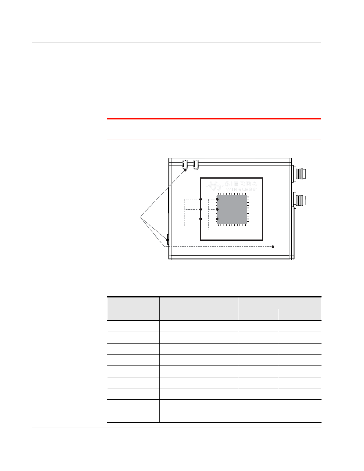
Sierra Wireless FX30 User Guide
FX30
WP Module
WP Module
GPIO
GPIO Pins
IOT Card
LEDs
Processor GPIO
FX30 Functions
and Signals
(LEDs, IOT card,
GPIO pins, etc.)
MDM Processor
WP Module Internal GPIO Mapping
Table D-2 shows the mapping of the FX30 function (or signal name) to the WP
module GPIO pin number and to the WP module internal processor GPIO
number.
For example, the IOT DETECT function is GPIO25 on the WP module, which
maps internally to GPIO73 on the MDM processor for the WP85 module and to
GPIO51 for WP76/77 modules.
Note: The WP Module GPIO numbers are used for AT commands and Linux GPIO sysfs.
The MDM Processor GPIO is typically used for kernel development.
Figure D-1: FX30 GPIO Hierarchy
Table D-2: WP Module Internal GPIO Mapping
FX30 Function WP Module GPIO Processor GPIO
WP85 WP76/77
IOT DETECT GPIO25 73 51
IOT GPIO1 GPIO42 80 79
IOT GPIO2 GPIO33 78 78
IOT GPIO3 GPIO13 84 76
IOT GPIO4 GPIO8 29 58
Rev 4 March 2019 76 41110030
PB GPIO7 79 16
DIGITAL INPUT1 GPIO2 59 38
DIGITAL INPUT2 GPIO21 50 8
DIGITAL INPUT3 GPIO22 49 9
Page 77

FX30 Linux Interface and GPIO Mapping
Table D-2: WP Module Internal GPIO Mapping
FX30 Function WP Module GPIO Processor GPIO
WP85 WP76/77
GPS LNA EN EXT_GPIO_LNA_EN 86 54
IOT PCM OUT PCM_OUT 23 22
IOT PCM IN PCM_IN 22 21
IOT PCM CLK PCM_CLK 20 23
IOT PCM SYNC PCM_SYNC 21 20
IOT SPI1 MRDY SPI1_MRDY 9 2
IOT SP1 MOSI SPI1_MOSI 11 0
IOT SP1 MISO SPI1_MISO 10 1
IOT SP1 CLK SPI1_CLK 8 3
IOT UART2 TX UART2_TX 18 13
IOT UART2 RX UART2_RX 19 12
IOT UART2 CTS UART2_CTS 76 15
IOT UART2 RTS UART2_RTS 64 14
IOT PPS DR_SYNC 85 53
IOT RESET OUT GPIO6 66 PMIC GPIO5
QUERY U705A ANT_CNTL3_EXT 27 48
QUERY U705B ANT_CNTL2_EXT 26 47
UICC1 DETECT UIM1_DET 0 34
UICC2 DETECT UIM2_DET 4 30
ADC RANGE ANT_CNTL1 25 46
ULPM WAKE1 GPIO36 36 SWIMCU PTA0
ULPM WAKE2 SPI2_CLK 38 SWIMCU PTB0
Rev 4 March 2019 77 41110030
Page 78

E: FX30 Factory Configuration
eSIM support
Some FX30 variants (such as FX30 Cat-1 WP7607-1) support eSIM. The external
2FF SIM slot is the preferred slot, but the internal eSIM will be used if no external SIM
is inserted. You can change the slot using the AT command AT!UIMS or the Legato
command cm sim select.
Note: If SIM AUTO SWITCH is enabled, the !UIMS setting is updated to reflect the preferred
slot. See SIM AUTO SWITCH below .
AUTO-SIM
The AUTO-SIM feature applies to Cat-1 and Cat-M variants, and is enabled by
default. This feature reboots the device and loads the carrier configuration (PRI) that
corresponds to the SIM. For example, if the external slot is enabled, and a Sierra SIM
is inserted, the Sierra carrier PRI will be loaded. By default, if a carrier PRI does not
exist (the SIM’s carrier does not match a PRI loaded on the radio module), the generic
carrier PRI is loaded. Note that the AUTO-SIM feature is not persistent over a
firmware update; however, you can re-enable it by using the AT command
AT!IMPREF="AUTO-SIM".
E
SIM AUTO SWITCH
The SIM AUTO SWITCH feature applies to Cat-1 (R10.1.1 and later) and Cat-M (R11
and later) variants. This is a customization that allows a user to select the preferred
slot. By default, the external slot is the preferred slot. You can change the preferred
slot by executing the AT command AT!CUSTOM="UIMAUTOSWITCH".
Note: This command requires level 2 unlocking . See the WP8548/WP75xx/WP76xx/WP77xx
AT Command Reference for more information.
Rev 4 March 2019 78 41110030
Page 79

FX30 Factory Configuration
AirVantage Management Services Polling Mode
The default FX30 configuration setting for AVMS Polling Mode is 60 minutes. The
AT command to change the setting is AT+WDSC=3,x where x is the number of
minutes. See the WP8548/WP75xx/WP76xx/WP77xx AT Command Reference
for more information.
Note: If you are experiencing issues with your FX30 not automati cally checking in with
AVMS, then query the AV Polling rate using AT+WDSC?
If the result is +WDSC: 3,0 then AV Polling is disabled. Please enable polling using
AT+WDSC=3,60 to set the polling rate to 60 minutes.
AirVantage Management Services User Agreements
The default FX30 configuration for AVMS User Agreements is “Disabled” for the
following modes:
• AVMS connection
• Package download
• Package install
• Device reboot
• Application uninstall
The AT command to change the user agreements is AT+WDSC. See the
WP8548/WP75xx/WP76xx/WP77xx AT Command Reference for more
information.
UART Settings
The default FX30 configuration setting for UART1 is for AT Command Service,
and UART2 is disabled. The AT command to change the setting is AT!MAPUART.
Rev 4 March 2019 79 41110030
Page 80

Index
A
AC power adaptor, 59
Accessories, 8, 58
AirVantage Management Services (AVMS), 36, 79
Analog input, 27
Antenna
Connecting, 18
Maximum gain, 55
AT commands, 32, 65
AUTO-SIM, 78
C
Cable strain relief, 20
Cables, connecting, 20
Certification
Industry Standards, 37
Mobile Network Operator, 37
Communication, command line prompt, using, 29
Current sink, 28
D
DC power cable
Specifications, 58
Wires, 21
Digital output, 29
E
Environmental Testing, 37
eSIM support, 78
Ethernet LEDs, 30
F
Installation
Connect data cables, 20
Connect power cable, 21
Connecting antennas, 18
Fixed (with I/O), 24
Insert SIM cards, 11
Overview, 10
Tools and materials required, 10
IoT expansion card, 11, 51
IP address, obtaining with command line prompt, 29
L
LED, description of LED, 29
LTE, bands supported, 38
M
MTBF
AC adapter, 60
O
Open drain, 29
Operating voltage, 38
Output, digital, 29
P
Pinging the router with command line prompt, 29
Power
Connecting, 21
Connector, 21
Power consumption, 49
Power modes, 47
Pull-up resistor, 27
Features, 7
G
GNSS, 39
Grounding the chassis, 18
R
Regulatory information, 55
Regulatory specifications, 60
RF specifications, 18
S
H
Host Interfaces, 38
I
I / O Configuration, 25
Input
Analog, 27
Dry contact switch, 27
On/off switch, 26
Rev 4 March 2019 80 41110030
Screw torque, 38
SIM AUTO SWITCH, 78
SIM cards, insert, 11
Specifications, 37
Environmental, 37
Environmental testing, 37
GNSS, 39
Input / Output, 38
Regulatory, 60
RF, 18
Standards, regulatory, 60
Page 81

T
Tools required for install, 10
U
UART, 54, 77, 79
W
Warranty, 9
Wiring diagrams, 23
WP radio module
AT commands, 32
Interface mapping, 73
WP7601-1 radio module
Conducted transmit power, 42
Frequency bands, 40
WP7603-1 radio module
Conducted transmit power, 43
Frequency bands, 40
WP7607-1 radio module
Conducted transmit power, 43
Frequency bands, 40
WP7702 radio module
Conducted transmit power, 43
Frequency bands, 41
WP8548 radio module
Conducted transmit power, 42
Frequency bands, 39
Index
Rev 4 March 2019 81 41110030
 Loading...