

Page 1

SIERRA VIDEO SYSTEMS, INC.
DigiLinx Three Rack Unit, 18 Module Frame
807121-00
V1.1
Page 2
Introduction
The three rack unit (3 RU) DigiLinx frame provides for 18 ‘single slot’ DigiLinx modules or 9 ‘two slot’
modules. The rear panel is equipped with two SmartLinx network connectors allowing the SmartLinx
network cabling to ‘loop through’ the frame. A single power supply is provided with the basic model while
two identical power supplies are provided with the redundant power supply version.
Peripheral Connections
807121-00:
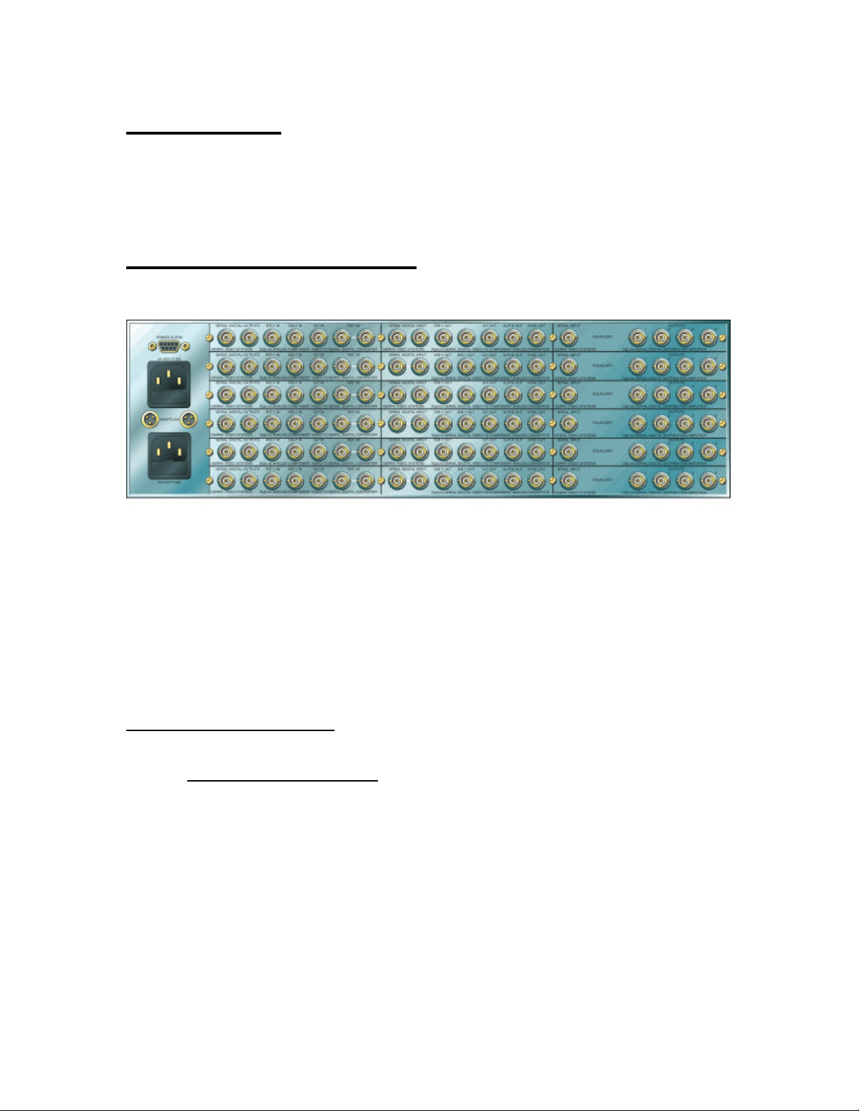
The rear panel provides the following connections to the user:
POWER - Each of the two IEC compatible power inlets contains two user accessible 4A, 250V fuses
(5X20mm). The upper power inlet serves the left hand power supply (as viewed from the front of
the frame) while the lower power inlet serves the right hand power supply (as viewed from the
front of the frame). Single supply chassis will use the lower inlet only.
SMARTLINX - These “Mini XLR” connectors provide external access to the SmartLinx control bus
which is connected to each module within the frame. The connectors are wired to each other to
allow the network signals to ‘loop through’ the frame passively. The pins are numbered as
follows:
Table 1:SmartLinx connector Pinout
Pin
Number Description
1 SmartLinx ‘A’
2 Ground
3 SmartLinx ‘B’
DigiLinx 3 RU Frame User’s Guide 2
Page 3

SmartLinx Functionality
The SmartLinx connections to the frame allow multiple frames to be ‘daisy chained’ together to create a
network containing over 150 modules. While a SmartLinx controller (such as a Host Adapter) may be
installed in this frame, it is not necessary to do so. Any controller anywhere in the network can control all
modules within the network. Note that these connections are passive and that the failure of any frame
within the network does not disable the rest of the network (unless the only controller is installed in the
disabled frame).
The frame also contains passive circuitry that allows the frame to identify itself (through SmartLinx modules
plugged into it) to the SmartLinx controllers. Each frame has a frame address, which can be changed using a
pair of jumpers accessible through the front of the frame with the front panel removed. If a new frame does
not appear on a network containing more than one such frame, the new frame may be set to an address
already in use. The switches within the 807110 should be changed until the SmartLinx controllers on the
network independently identify all such frames. The frame address selection jumper is reached by removing
either power supply or the blank plate (if a single supply is being used). The jumper connects 2 of twelve
pins to choose a frame addressed as defined by the label next to the jumper. This address value is that seen
from the Windows software view of the network. Note that power must be cycled to the frame to force the
modules to re-read their frame address. No 3 rack unit frame addresses overlap with any 1 rack unit or
desktop frame addresses.
The frame also contains passive ‘slot ID’ circuitry which indicates the position of specific modules within
the frame. Slots are numbered 1 through 18 starting with the upper leftmost slot (as viewed from the rear of
the frame) and incrementing from top to bottom, then left to right.
The three conductor in-line connectors which mate with the SmartLinx connectors on DigiLinx frames are
supplied with each shipped frame (two per frame). They are Switchcraft part number TA3F, available
directly from Sierra Video Systems.
Power Supply Installation
Power Supply subassemblies can be replaced or installed by the customer in the field. Note that this
procedure requires the removal of power from the frame, as high voltage parts are accessible within the
power supply subassemblies. Replacement or addition of power supply assemblies requires the use of a
Philips screwdriver. Replacement or addition of power supply assemblies does not require the removal of
the frame from its relay rack.
To add a supply to a single supply frame, the blank front panel of the frame(the panel with no LED’s) is
removed by unscrewing the six black Philips screws which hold the panel to the frame. The same six screws
will be used to fasten the added power supply assembly to the frame. The new power supply assembly is
connected to AC power via a three pin male connector on the right side of the assembly. Looking into the
front of the frame, an umbilical ending in a three pin female connector should be visible. This umbilical is
plugged into the three pin connector on the new power supply assembly such that the green wire of the
umbilical is adjacent to the ground symbol on the power supply. The plastic retaining clips on the power
supplies AC connector should be facing the ‘smooth’ (no holes) side of the umbilical connector. The
twenty pin umbilical cable coming from the power supply assembly plugs into the twenty pin connector on
the motherboard of the frame which is visible with the blank front panel removed. Orient the connector to
that the plastic retaining ramps on the umbilical connector face the plastic retaining clips on the
motherboard connector. After the two connectors have been installed, the power supply module can be
attached to the frame using the six black screws removed from the blank plate. Care should be taken to
avoid ‘pinching’ umbilical wires between the power supplies front plate and the front flanges of the frame.
DigiLinx 3 RU Frame User’s Guide 3
Page 4

To replace a supply to a dual supply frame, the supply assembly to be replaced is removed by unscrewing
the six black Philips screws which hold the panel to the frame. The same six screws will be used to fasten
the added power supply assembly to the frame. The new power supply assembly is connected to AC power
via a three pin male connector on the right side of the assembly. An AC power umbilical cable should be
attached to the supply assembly being removed. Remove this AC cable from the old supply assembly and
attach it to the same connector on the new power supply assembly such that the green wire of the umbilical
is adjacent to the ground symbol on the power supply. The plastic retaining clips on the power supplies AC
connector should be facing the ‘smooth’ (no holes) side of the umbilical connector. The twenty pin
umbilical cable coming from the old power supply assembly should be unplugged from the motherboard in
the frame and returned to the factory attached to the old power supply. The twenty pin umbilical cable
coming from the new power supply assembly plugs into the twenty pin connector on the motherboard of the
frame made available by the removal of the old power supply. Orient the connector to that the plastic
retaining ramps on the umbilical connector face the plastic retaining clips on the motherboard connector.
After the two connectors have been installed, the power supply module can be attached to the frame using
the six black screws removed from the blank plate. Care should be taken to avoid ‘pinching’ umbilical wires
between the power supplies front plate and the front flanges of the frame.
Power Supply Indicators
Each power supply module is equipped with a front panel featuring 3 power indication LED’s. The LED’s
indicate (from top to bottom); +5V power OK, +8V power OK, and –8V power OK. All three of these
indicators should glow green to indicate a fully functional frame. Note that these indicate the status of the
power supply they are mounted to. This means an LED may correctly indicate a failed supply without a
module malfunction because the other power supply (if purchased) is still functional .
Application Notes
Power supply replacement/installation should not be attempted while power is applied to the chassis. While
the AC harnesses are insulated, the high voltage circuitry within the power supply is not.
Cooling the frame requires an air gap to the left and right of the chassis. The air gap afforded by normal
relay rack spacing should be sufficient. Any unused module locations should be filled with blank DigiLinx
rear panels to maintain proper air resistance within the frame.
DigiLinx 3 RU Frame User’s Guide 4
Page 5

Specifications
Power Input- 100 to 240V, 50-60Hz, <100VA
Power Output(max)- +5V: 25A
+8V: 9A
-8V: 2.5A
Operating Temperature- 0 to 50C(non condensing)
Operating Humidity- 5-95% RH(non-condensing)
Depth (from relay rack mounting surface)- 17 inches (432 mm)
Height - <5.25 inches (<134 mm)
Width- (not including rack mnt. extensions)- <17.3 inches (<439 mm)
DigiLinx 3 RU Frame User’s Guide 5
 Loading...