

Page 1

SIERRA VIDEO SYSTEMS, INC.
DigiLinx One Rack Unit, 6 Module Frame
and Optional SmartLinx Local Control Panel
807110-00 (frame)
804711-00 (control panel)
V2.0
Page 2
Introduction
The one rack unit (1 RU) DigiLinx frame provides for 6 ‘single slot’ DigiLinx modules or three ‘two slot’
modules. The rear panel is equipped with two SmartLinx network connectors allowing the SmartLinx
network cabling to ‘loop through’ the frame. A simple power indicating front panel is provided with the
standard product while a built-in SmartLinx LCD control panel can be added as an option.
Peripheral Connections
807110-00:
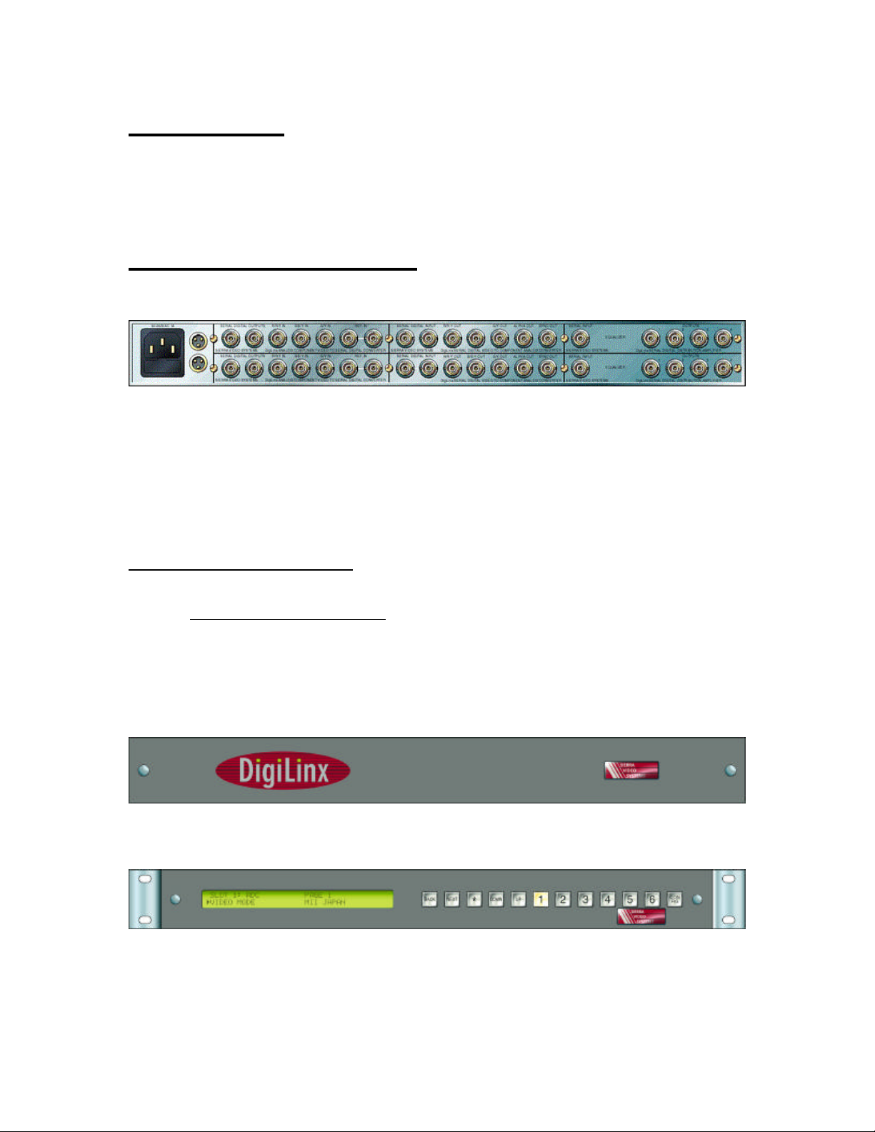
The rear panel provides the following connections to the user:
POWER - This IEC compatible power inlet contains a user accessible 4A, 250V fuse
SMARTLINX - These “Mini XLR” connectors provide external access to the SmartLinx control bus
which is connected to each module within the frame. The connectors are wired to each other to
allow the network signals to ‘loop through’ the frame passively. The pins are numbered as
follows:
Table 1:SmartLinx connector Pinout
Pin
Number Description
1 SmartLinx ‘A’
2 Ground
3 SmartLinx ‘B’
807110-00 Standard Front Panel:
804711-00 Optional Local Control Panel:
DigiLinx 1 RU Frame User’s Guide 2
Page 3

SmartLinx Functionality
The SmartLinx connections to the frame allow multiple frames to be ‘daisy chained’ together to create a
network containing over 150 modules. While a SmartLinx controller (such as a Host Adapter) may be
installed in this frame, it is not necessary to do so. Any controller anywhere in the network can control all
modules within the network. Note that these connections are passive and that the failure of any frame
within the network does not disable the rest of the network (unless the only controller is installed in the
disabled frame).
The frame also contains passive circuitry which allows the frame to identify itself (through SmartLinx
modules plugged into it) to the SmartLinx controllers. Each frame has a frame address, which can be
changed using a pair of jumpers accessible through the front of the frame with the front panel removed. If a
new frame does not appear on a network containing more than one such frame, the new frame may be set to
an address already in use. The switches within the 807110 should be changed until the SmartLinx
controllers on the network independently identify all such frames. No 1 rack unit frame addresses overlap
with any 3 rack unit or desktop frame addresses.
The frame also contains passive ‘slot ID’ circuitry which indicates the position of specific modules within
the frame. Slots are numbered 1 through 6 starting with the upper leftmost slot (as viewed from the rear of
the frame).
The three conductor in-line connectors which mate with the SmartLinx connectors on DigiLinx frames are
supplied with each shipped frame (two per frame). They are Switchcraft part number TA3F, available
directly from Sierra Video Systems.
Power Supply Indicators (standard front panel)
The non-local control panel version of the 1 RU frame is equipped with a front panel featuring 3 power
indication LED’s. The LED’s are located behind the ‘dots’ of the ‘I’s in the DigiLinx trademark on the
panel face. The LED’s indicate (from left to right); +5V power OK, +8V power OK, and –8V power OK.
All three of these indicators should glow green to indicate a fully functional frame. Note that some versions
of this frame require a minimum load current to provide stable power. An under-loaded frame will indicate
its condition by flashing its LED’s roughly once per second. Under-loaded frames can be stabilized by
adding additional modules or by adding the DigiLinx Power Monitor module (507105-00) to the frame.
Local SmartLinx Control Panel (optional)
Introduction
This section describes the make-up and operation of the “One rack unit” (hereafter known as ‘1 RU’)
local control panel. Mounted directly on the front of a 6-module DigiLinx frame, this device provides
access to and control of any DigiLinx module installed in that frame via the SmartLinx communication
protocol. The internal electronic connection between the panel and the frame provides the panel with
power and an RS485 serial connection for the SmartLinx interface.
Access and control of a DigiLinx module consists of viewing and/or modifying parameters specific
to the currently selected module. Some examples of module parameters would be line mode, video
standard, delay values, video gains and offsets, etc. While some parameters are common to several
DigiLinx products, others are unique to a single product.
DigiLinx 1 RU Frame User’s Guide 3
Page 4

Description
The 1 RU control panel allows a user to interact with DigiLinx modules, reading and altering values
that affect the operating parameters of those devices. This interaction occurs within two distinct
operating modes:
1. “Normal” – user interacts with the modules and their respective parameters, and
2. “Config” – user interacts with the panel and its operating characteristics.
In either mode, interaction occurs via a pushbutton and LCD display interface.
Modules may be removed, replaced with another module, or moved to another slot within the frame
without powering down or resetting the unit. Detection of the presence and disappearance of modules
is automatic.
The panel may be disabled, disconnecting it from the SmartLinx interface, allowing another host
device to interact with the frame and its modules. When disabled, the user only has access to the
Config mode on the panel. Cycling the unit through a power-down, power-up sequence will retain the
state of the panel; i.e., if disabled when powered down, the panel will remain disabled after power-up.
Panel Components
The control panel is comprised of two major physical components, a 12-button keypad and a LCD
display, that make up the user interface for this device.
Keypad
The keypad consists of 12 individually lit pushbuttons arranged in a single row to the right of the
display. They are organized by functionality into 4 groups. Buttons that navigate the display are
located closest to it, those that select specific modules are to the right of the navigator buttons, and a
single button to enter and exit config mode is located at the far right.
The following subsections describe each of the 4 groups of buttons, starting at the left end of the
keypad and progressing successively to the right.
Navigator Keys
These are the 3 leftmost buttons and consist of two field selector keys – ‘Back’ and ‘Next’, and a
character selector key – the ‘*’ or ‘star’ key. The field selector keys move the user from field to field
on the display, in the direction relevant to the key’s name. The character selector key moves the user
from character to character within a single field. Though capable, these keys are never lit by any
operation performed on the panel.
Note that the ”star” key may be considered a dual-purpose key – a navigator key as described above,
and an operator key. As an operator key, this button is used to initiate an operation such as “save
parameters to EEPROM” when prompted by the display.
DigiLinx 1 RU Frame User’s Guide 4
Page 5

Operator Keys
The next 2 buttons on the keypad are the operator keys – ‘Up’ and ‘Down’. These keys allow the user
to:
1. Select a particular module parameter to be viewed or modified.
2. Change the value of a selected parameter.
3. Select a particular slot and the associated module that is mounted in it.
4. Change characters within a string of characters.
5. Enter a password.
Changes made with these keys may be done as single press increments or by holding the key pressed,
causing the value being changed to scroll through the selections available. In “hold-down” operation,
values begin changing rapidly in the direction of the operator key after an initial half-second of delay.
Like the Navigator Keys, these buttons remain unlit during the operation of the panel.
Module Selection Keys
These 6 buttons, labeled 1 to 6, allow the user to immediately select a particular slot. Each slot may
or may not contain a module and the display will reflect that fact with the appropriate error message or
if populated, that module’s starting information.
The lights on these buttons are activated and have a specific meaning. When lit, they indicate that a
SmartLinx module is present in the slot indicated by the key name. When unlit, they indicate an
empty slot.
Mode Select Key
This is a single button used to select one of two operation modes on the panel – “normal” vs.
“configuration”. Button presses to this key toggle between the two modes.
The light within this button is always lit as an indication that power is being supplied to the panel.
DigiLinx 1 RU Frame User’s Guide 5
Page 6

Display
Information is presented to the user via a 40 x 2 character LCD display located on the left side of the
panel. This screen is divided into four 20 character fields labeled 1 – 4. This division of fields is
maintained in both operating modes (normal or config).
‘field 1’
Title
Field Select Indicator
‘field 3’
Parameter Selection
Catalog Num4: Tcache – 1.87sec
TimeCash
‘field 2’
Comment
Figure 1: LCD display organization (normal mode shown).
Common Field Organization
The first character of each field is reserved as a field select indicator and in the case of ‘field 4’, to
display special characters relevant to the information displayed in that field. The field select indicator
is a “right facing” triangle that indicates the current field that the user has control of.
517135
‘field 4’
Parameter Value
Field 1: Title field
In normal mode, this field displays the currently selected slot number and a fixed title for the Digilinx
module installed in that slot. A blinking cursor is positioned on the slot number and the ‘Up’ and
‘Down’ keys will incrementally change the slot selection. No other control is possible within this
field.
In config mode, this field displays a fixed banner – “-- Config Mode --”. This is a display-only field
and can not be selected with the navigator keys.
Field 2: Comment field
In normal mode, this field displays a user adjustable comment field – 8 characters in length. The
‘star’ key is used to position the cursor. The ‘Up’ and ‘Down’ keys are used to change the character
at the current cursor position.
DigiLinx 1 RU Frame User’s Guide 6
Page 7

In config mode, this field displays a fixed banner – “’Config’ to exit”. The banner notifies the user
how to exit config mode to return to normal mode. This is a display-only field and can not be selected
with the navigator keys.
Field 3: Parameter Selection field
In either mode, this field displays the currently selected element from a list of elements. That element
may be any of the following forms:
• A description of a module parameter whose current “value” is displayed in ‘field 4’.
• A description of an operation with an associated “prompt message” displayed in ‘field 4’.
• A description of an operation with an associated “entry field” in ‘field 4’ (config mode only).
Successive elements of the list behind ‘field 3’ are selected using the ‘Up’ and ‘Down’ keys in the
direction associated with the key being used. The list is circular, wrapping from the end to the
beginning or vice-versa depending on the direction of change.
Field 4: Parameter Value field
In either mode, this field displays a “value” or “prompt” associated with the current contents of field
3. It is within this field that primary control of each module takes place. The size and content of the
values displayed within this field are entirely dependent on the parameter associated with it.
As mentioned before, the first character position in this field is used to display characters relevant to
the information being shown. These characters are only displayed when ‘field 4’ is NOT the currently
selected field. When it is the currently selected field, the special characters are replaced with the field
select indicator. There are three characters used for this purpose:
1. A blank – which indicates that the value currently on display is read-only and navigation into
this field is prohibited. Use of the ‘Back’ and ‘Next’ keys when this is the next field to select
will skip this field and go to the one beyond (‘field 1’) or before it (‘field 3’).
2. An asterisk – which indicates that the value currently on display is editable. Navigation into
this field is allowed.
3. A capital P – which indicates that the value currently on display is password protected and
navigation into this field is prohibited. One of the features of config mode is to enter a
password and unlock any protected values.
DigiLinx 1 RU Frame User’s Guide 7
Page 8

Operation
This section describes in detail the operational features of the 1 RU control panel. It is organized into
three major sub-sections – power-up, normal mode, and config mode.
Power-Up
There is no actual power switch associated with this device. Power-up occurs when the 1 RU frame
that the control panel is mounted on is plugged into a power outlet.
During power-up, the panel will attempt to make contact with each slot in the frame to determine if a
module is present in each one of them. It will then light each associated lamp on the slot keys that
have a module present. The panel software will then select the first module that responds to a
particular SmartLinx message. This could be any of the 6 possible modules present. Once selected,
the panel will display the “start screen” for that module and use of the panel will proceed from there.
The “start screen” is the same for any module selected – ‘field 3’ is set to the first parameter in its
“list” (always the SVS catalog number) while ‘field 4’ displays the actual value of that parameter.
‘Field 1’ is the active field with the cursor positioned over the slot number.
Normal Mode
These sub-sections describe the operations involved with reading and changing parameters specific
to the DigiLinx modules installed in the frame.
Slot Selection
There are two methods for selecting a slot and the module installed within it:
1. Directly – by pressing one of the six slot selection keys.
2. Successively – while ‘field 1’ is the current active field, using the ‘Up’ and ‘Down’ keys to
progressively move through the slots.
Exceptions
If no module is installed in the selected slot or communication with an installed module does not
succeed, an appropriate message is displayed in ‘field 1’ after the slot number and the other three
fields are left blank and inaccessible:
• “No SmartLinx” – slot is empty.
• “No Database Template” – slot contains a module for which a database template has not
been developed.
• “Unknown Subtype (Dash#: )” – slot contains a module whose subtype is unknown to its
database template.
• “Module disconnected” – a ‘disconnect’ occurred while trying to communicate with the
module.
DigiLinx 1 RU Frame User’s Guide 8
Page 9

Initial State of Selection
Whenever a change in slot selection is made, the display is set up with the “start screen” of the newly
selected module.
Field Selection
Field selection is performed with the two field selector keys – ‘Back’ and ‘Next’. As each of these
keys is pressed, the field select indicator character (a right facing triangle) is erased from the
beginning of the current field and displayed at the start of the new field. Successive presses of these
keys advances the indicator from field to field in the direction associated with the key name. Pressing
the ‘Next’ key while in ‘field 4’ advances the selection to ‘field 1’. Pressing the ‘Back’ key while in
‘field 1’ advances the selection to ‘field 4’. When ‘field 4’ is not selectable (the value displayed is
read-only or password protected), it is skipped over with the use of these buttons – ‘Next’ takes the
user from ‘field 3’ to ‘field 1’ and ‘Back’ takes them from ‘field 1’ to ‘field 3’.
HINT: after power-up or a change in slot selection, the panel has ‘field 1’ selected and ‘field 4’ is
read-only (“start screen”). Pressing the ‘Back’ key immediately takes the user to ‘field 3’, where
parameter selection can begin.
Module Parameter Selection
When ‘field 3’ is the currently selected field, the user has access to the parameter and operator list
(hereafter referred to as “the list” or “list”) for the currently selected module. This is a circular list
that is navigated with the operator keys – ‘Up’ and ‘Down’.
Moving Through “the List”
‘Field 3’ displays the name of the parameter or operator selected. That name is not editable; thus,
no cursor appears in this field. It can be any string of valid characters up to 19 characters in length.
As new members of “the list” are selected via the ‘Up’ and ‘Down’ keys, the “values” associated with
parameters or the “prompts” associated with operators are displayed in ‘field 4’. Each time a new
parameter is selected, its value is read via the SmartLinx interface from the module. Each time a new
operator is selected, an appropriate prompt is displayed in ‘field 4’
HINT: Because “the list” is circular, the most commonly accessed parameters are located at the end.
When a new module is selected, the first item in “the list” is displayed. Upon selecting ‘field 3’, the
user can press the ‘Down’ key and immediately begin accessing the more common parameters for
that module.
Concatenated Descriptions
The description displayed in ‘field 3’ may be a concatenation of the current value of another
parameter in “the list” and the currently selected parameter’s description. For example:
The current parameter is a video gain (say “UBGain”) whose specific value depends on the current video mode (say
“BetaCam”). The actual description displayed in ‘field 3’ would be “BetaCam UBGain”. A subsequent change in the
video mode to “MII” and re-selection of the video gain as the current parameter would result in a different description
– “MII UBGain”.
DigiLinx 1 RU Frame User’s Guide 9
Page 10

Skipping “List” Members
A complete “list” contained in any given module’s database template may contain members whose
selection is conditional. If the conditions are not met, that member will be skipped and the next
member in “the list” will be examined. If it does not qualify, it too will be skipped and so on until a
member is found that can be selected. Both parameter and operator type members can be skipped.
A parameter may be skipped for one of two reasons:
1. It is “restricted”. This can be because its value may be irrelevant unless another “boolean”
type parameter is turned on. For example:
The SlideCache module has a parameter whose value reflects the presence of reference video and another
parameter whose value reveals the line mode of that video. If no reference video is detected, then the 2
parameter’s value is meaningless.
2. It is not a member of the “feature set” specific to the module sub-type that is installed. Some
DigiLinx modules have multiple implementations known as sub-types. Not all members of
“the list” are relevant to every sub-type. For example:
An ADC module has a key-only type, a video-only type, and a video & key type module, three distinct subtypes distinguished by their respective dash numbers. While the ADC module’s database template contains the
entire “list”, only a subset of members may be relevant to a given sub-type. Those that are not will be skipped
when navigating the parameter list.
An operator may be skipped for two entirely different reasons:
1. Its action is to save a read-only value or values. The currently read-only value may be a
member of a set of values, some of which are read-only and some of which are not. When the
user changes that value to one that is write-able, then the “save” operator will not be skipped
when navigating “the list”.
2. Its action is directed at a parameter whose value is password protected and the password is
currently locked or enabled.
Changing Module Parameter Values
When ‘field 3’ is the currently selected field, the user has the ability to change a parameter’s value.
Changes are made with the operator keys – ‘Up’ and ‘Down’, within a range for that value as
specified in the module’s database template.
nd
Types of Values
There are 3 types of values that can be displayed:
1. Signed or unsigned integer – one, two, three or four bytes.
2. Boolean – whose actual value is zero or one, but whose displayed value is translated into an
appropriate string – yes or no, enabled or disabled, etc.
3. String – whose actual parameter value is an unsigned single byte integer, which is used as an
index into a list of strings.
Upon entry into this field, the display will differ slightly depending on the type of value being shown.
Integer values will have a blinking cursor positioned on the rightmost digit (one’s digit). The field
size will depend on the maximum allowed value for that integer and leading zero’s will be displayed
as a blank character.
DigiLinx 1 RU Frame User’s Guide 10
Page 11

Strings will have no cursor displayed, but will have a left pointing triangle in the first character
position to the right of the last character in the string. This triangle along with the right pointing
triangle (field select indicator) at the beginning of the field effectively brackets the displayed string.
As different string values are selected and their lengths vary, the left triangle’s position changes to
accommodate the new size. Because of this, string sizes are limited to 18 characters – 20 character
field minus field indicator position minus left triangle position.
Cursor Position Affects Increment or Decrement of Change
When changing the value of an integer, the amount of change is determined by the cursor position.
This position can be adjusted with the ‘star’ key. Upon entry into this field, the cursor is placed over
the one’s position and any change will increment or decrement the value by one. The ‘star’ key will
move the cursor to the left through the tens, hundreds, and so on positions, causing increments or
decrements by the associated power of ten. When the cursor is above the leftmost position of the
integer (leading blanks included), a subsequent press of the ‘star’ key will reset the cursor to the ones
position.
Handling Limits for Integer Values
When changing integer values and the amount of change would result in a value beyond the maximum
or minimum limit for that parameter, then the change is ignored. When the change would result in a
value at the limit, then it is applied.
Changing String Values
When the current parameter value is displayed as a string, then the user effectively cycles through a
circular list of strings as they make selections with the ‘Up’ and ‘Down’ keys. In the case of a ‘type 2’
value, only two strings reside in the list and it does not matter which of those two keys is used. Each
of them merely toggles between the two selections. In the case of a ‘type 3’ value, a list with at least
three or more strings exists. That list will wrap at the beginning and end when those boundaries are
crossed.
Split Field Values
Some integer values are stored in one dimension but displayed in another. For example, the
TimeCache module has a delay value that is stored in number of clocks. This value can be quite large
(100’s of millions) and cumbersome from the user’s point of view. Given that, the value is displayed
in a split field context as three sub-fields – frames, lines and clocks. Likewise, the FrameCache
module has a skew value that is stored in number of clocks but displayed as two sub-fields – lines and
clocks.
All sub-fields are displayed within the 20-character ‘field 4’ but are treated as separate fields for
navigation purposes. That is, the two field selector keys – ‘Back’ and ‘Next’, will move between the
sub-fields just as they do with the primary fields on the display. The cursor appears in the currently
selected sub-field and can be moved via the ‘star’ key with the same rules as described above. Note
however, that the underlying single value is actually being changed and re-displayed as separate fields.
Given that, a change in one sub-field may or may not cause a change in another sub-field.
Performing Module Parameter Operations
The operator members of “the list” allow the user to perform operations such as saving parameter
values to or recalling them from EEPROM. Normally, when changing parameter values, it is a
DigiLinx 1 RU Frame User’s Guide 11
Page 12

“current” set of values stored in the module’s RAM that are being manipulated. When the power to
the module is turned off those values go away. Upon power-up, the “current” set in RAM is recalled
from EEPROM. The user can make their adjustments more permanent by using the appropriate save
operation to place those values in EEPROM. Likewise, they can replace the “current” set of values
with those previously stored in the non-volatile memory.
When an operator member is encountered, a description of the parameter set is displayed in ‘field 3’
and a relevant prompt message is displayed in ‘field 4’. The user must select ‘field 4’ as the current
field to actually perform the operation. Once in ‘field 4’ the operation can be performed by doing
what the prompt message states to do, usually a press of the ‘star’ key.
Editing the Module’s Comment Field
‘Field 2’ is dedicated to displaying an editable 8-character string representing a user’s comments for
the installed module. This field is stored in the module’s EEPROM and thus follows it from frame to
frame. An example of a use for this field would be to store the initials of the technician who last
calibrated the module – “Calbydjw”.
After selecting ‘field 2’ as the currently active field, the display positions the cursor over the first
(leftmost) character in the 8-character field. The Up’ and ‘Down’ keys cycle through the character set
at the current cursor position. The ‘star’ key moves the cursor to the right through each character
position wrapping back to the first position (leftmost character) when the end of the entry field is
crossed. Each change of character causes an update of the string within the affected module.
Config Mode
These sub-sections describe the operations involved with reading and changing parameters and
operations specific to the control panel as a whole. Entering and exiting this mode is done
exclusively with the ‘ConFig’ key located in the rightmost position of the keypad.
Field Navigation
Only display ‘field 3’ and ‘field 4’ are accessible in config mode. The field selector keys – ‘Back’ and
‘Next’ each act to toggle between these fields.
The Config “List”
The “list” of parameters and operators contained in ‘field 3’ for config mode consists of five
members – 4 operators and 1 parameter, in that order. The following subsections describe each of
these members in the order that they appear in “the list”.
Enabling and Disabling Panel Operation
The first “list” member seen upon entry into config mode is an operator to disable or enable the panel
from the SmartLinx interface and therefore, disable or enable control of the slots and their installed
DigiLinx modules.
To perform this operation, select ‘field 4’ as the current field and use the operator keys to toggle the
state of the panel.
DigiLinx 1 RU Frame User’s Guide 12
Page 13

Once disabled and upon return to normal mode, only ‘field 1’ is displayed with the following
message: “Control Panel Disabled”. Since no other fields are active and ‘field 1’ is simply a message,
no control of the modules is possible.
Enabling and Disabling Password Protection
The second “list” member is an operator prompting the user to enter a password to unlock any
protected values. This protection is universal with respect to any and all modules installed in the unit.
To enter a password, select ‘field 4’ as the current field. The user is presented with an 8-character
entry field, bracketed on the right and left by the triangle characters, and a blinking cursor in the
leftmost character position. The ‘Up’ and ‘Down’ keys cycle through the character set at the current
cursor position. The ‘star’ key moves the cursor to the right through each character position wrapping
back to the first position (leftmost character) when the end of the entry field is crossed.
To finalize entry of the password, the user returns the control to ‘field 3’. If the password entered is
invalid, an appropriate message is displayed in ‘field 3’ and the user may select ‘field 4’ again and
retry the entry. There is no limit on how many attempts the user can make to enter a valid password.
If the password was valid, ‘field 3’ displays the message – “Disable Password” and ‘field 4’ displays a
prompt – “Press * to disable”. To return the system to password protection, select ‘field 4’ again and
press the ‘star’ key.
NOTE: After unlocking protection by entering a password and returning the panel to normal mode,
the capital P that was displayed in the first character position of ‘field 4’ for any protected values will
have disappeared. Those values are now accessible to change.
Changing the Password
The next two “list” members are operators used together to change the system password. Changing
the password is a two step process that requires the user to enter the old password so as to get access
to the operator that accepts the entry of a new value. If the user does not enter the old password
when that operator is selected, then the next operator (enter new password) is skipped when the
‘Next’ key is pressed.
The first operator allows the user to enter the old password (‘field 3’ description is “Chg PW(Ent
old PW)”) and the second allows the user to enter a new password (‘field 3’ description is “Chg
PW(Ent new PW)”). Password entry in both cases is via the same method as normal password entry
described above. However, the action taken in both cases when entry is finalized (‘field 3’ is selected)
is different.
When entering the old password, if an invalid password was entered, the display in ‘field 3’ remains
unchanged and the user may try again or abandon this operation. However, if a valid password was
entered, ‘field 3’ advances to the next operator asking the user to enter the new password. In this
operation, there is no such thing as an invalid entry, so any entry into ‘field 4’ is accepted and the
password is changed. Upon return to ‘field 3’, the panel remains positioned on this operation allowing
the user to enter a new password again. To exit this operation, the user needs to navigate the ‘field 3’
selection to the next or previous member on the “list” or exit config mode altogether.
NOTE: When performing a password entry into ‘field 4’ and the user returns to ‘field 3’ without
actually entering anything, no action is taken. The same operation is still active and the user may
DigiLinx 1 RU Frame User’s Guide 13
Page 14

select ‘field 4’ again and perform password entry, continue navigating the config “list”, or exit config
mode altogether.
Panel Software Version
The last member of the “list” is a read-only parameter that displays the current “panel software
version number” in ‘field 4’. This has the format – x.nn, where x is the major revision level and nn is
the minor. The first release of this software was 1.00.
Application Notes
Power requirements for DigiLinx modules vary significantly between the DA family products and the video
processing family products. The video processing family products are defined as ‘heavy loads’ and the DA
family products are defined as ‘light loads’. Some versions of this frame require a minimum of two ‘heavy
loads’ or a DigiLinx Power Monitor module (507105-00) to ensure stable power. Any number of ‘heavy
load’ modules (up to 6) can be installed without excessive power consumption concerns.
Cooling the frame requires an air gap to the left and right of the chassis. The air gap afforded by normal
relay rack spacing should be sufficient.
Specifications
Power Input- 100 to 240V, 50-60Hz, <100VA
Power Output(max)- +5V: 9A
+8V: 3A
-8V: 1.5A
Forced Air Flow(min) 15 CFM
Operating Temperature- 0 to 50C(non condensing)
Operating Humidity- 5-95% RH(non-condensing)
Depth (from relay rack mounting surface)- 17.875 inches (454 mm)
Height - 1.75 inches (68.9 mm)
Width- (not including rack mnt. extensions)- 17 inches (432 mm)
DigiLinx 1 RU Frame User’s Guide 14
 Loading...