

Sierra Products Pellet Heater EF5001B-AL, EasyFire EF5001B-AL Installation And Operating Instructions Manual
EF5001B-AL Pellet Heater
Installation & Operating Instructions
Please read this entire manual before installation. Save these instructions.
GENERAL INFORMATION
Installation and repair should be done by a qualified service
person. The heater should be inspected before use and at
least annually by a professional service person. More
frequent cleaning m ay be required due to fuel quality,
excessive lint from carpeting, bedding material, etc. It is
imperative that control compartm ents, burners and circulating air passageways of the heater be kept clean.
The EASYFIRE Pellet heater has been designed and
approved for burning wood pellet fuel only. Burning other
forms of fuel is not permitted and will void all warranties.
This unit has been approved for use with a 4" Type L Pellet
Vent System .
NEVER use gasoline, gasoline-type lantern fuels, kerosene,
charcoal lighter fluid, or similar liquids to start or "freshen
up" a fire. Keep all such liquids well away from the heater
while it is in use.
SAFETY NOTICE
<CAUTION: HOT WHILE IN OPERATION. KEEP
CHILDREN, CLOTHING AND FURNITURE AWAY.
CONTACT MAY CAUSE SKIN BURNS.
< IF THIS HEATER IS NOT PROPERLY INSTALLED,
A HOUSE FIRE MAY RESULT.
< FAILURE TO COMPLY W ITH OW NERS' M ANUAL
INSTRUCTIONS WILL VOID YOUR WARRANTY!
PLEASE READ THIS ENTIRE MANUAL BEFORE
INSTALLATION AND USE OF THIS PELLET FUELBURNING ROOM HEATER. FAILURE TO FOLLOW
THESE INST RUCTIONS COULD RESULT IN
PROPERTY DAMAGE, BODILY INJURY OR EVEN
INSTALLER: PLEASE LEAVE THIS MANUAL WITH
THE OWNER!!
WARNING: THIS HEATER SHOULD NOT BE
INSTALLED IN A SLEEPING ROOM.
Ashes must be disposed of in a metal container with a tight
fitting lid and placed on a noncombustible floor or ground,
well away from all fuels, pending final disposal.
NOTE : During the first few burns the high temperature
paint and sealant used in manufacture will emit some odor
and smoke. Open doors and windows to the outside for
proper ventilation during the first burn cycle and curing of
the paint.
This heater, when installed, must be electrically grounded in
accordance with local codes or, in the absence of local
codes, with the National Electrical Code, ANSI/NFPA 70-
2006.
Provide adequate clearances around air openings into the
combustion chamber and adequate accessibility clearance
for servicing and proper operation. Never obstruct the front
opening of the heater.
The heater may be installed as a free-standing unit mounted
on a non-com bustible protective floor pad or hearth. Or it
may be m ounted into an existing U. L. approved wood stove
chimney. Non-combustible floor protection is required and
must be used when placing the heater on any com bustible
material.
The pellet heater must be operated with a power source and
will not operate using natural draft. If there is a power failure
the heater will shut down. If the 12 volt back system is installed, the heater will automatically switch to 12 volt power.
The EasyFire Pellet Heater has been listed by OMNI-Test
Laboratories, Inc. to ASTM, U.L.,and EPA Standards.
Sierra Products, Inc.
5061 Brooks St., Ste. B
Montclair, CA 91763
Listed by OMNI-Test Laboratories, Inc.
Report No. 256-S-01-4
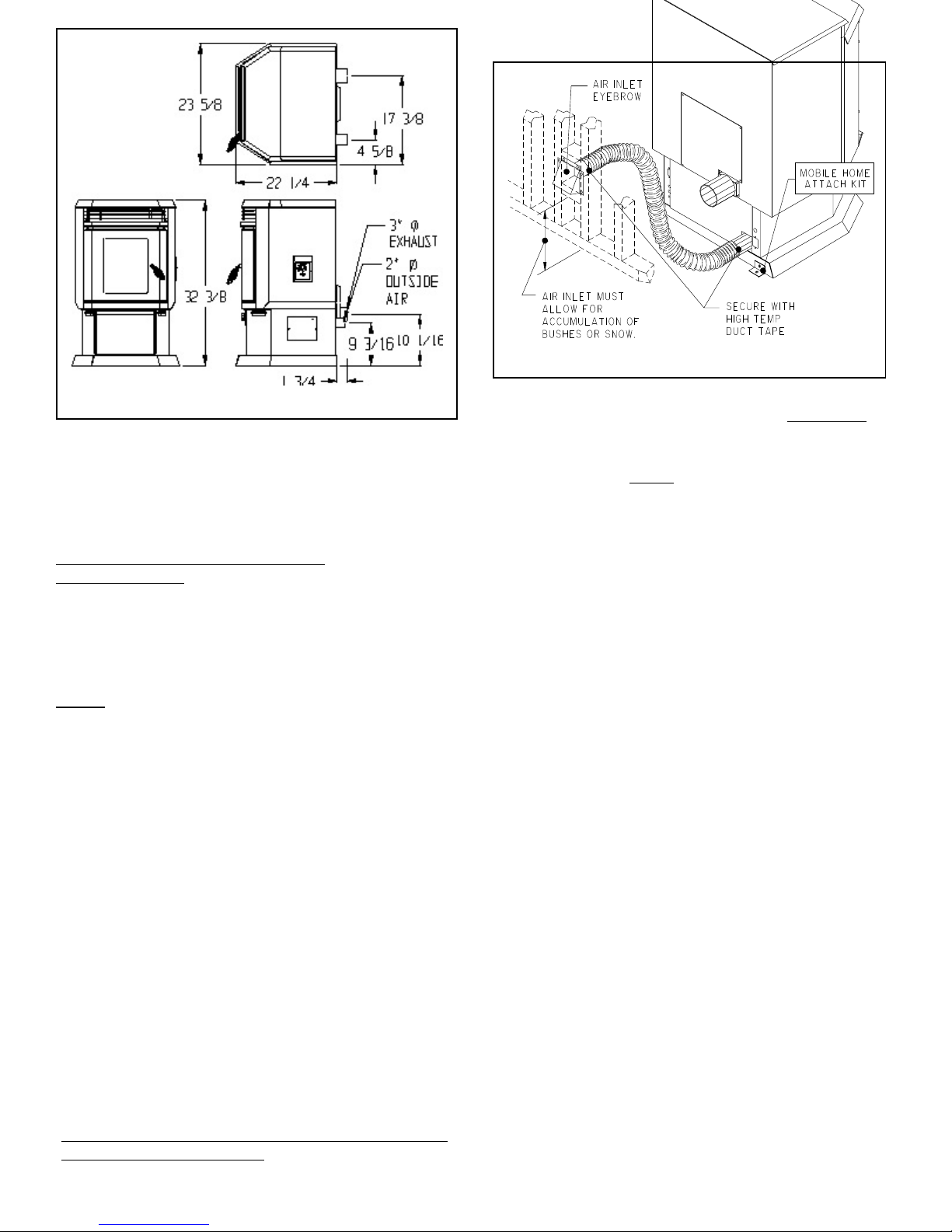
Figure 2
Figure 1 -Overall Dimensions
OUTSIDE COM BUST ION AIR IS MAN DAT ORY IN
MOBILE OR MODULAR HOME INSTALLATIONS.
CAUTION: DO NOT CONNECT TO ANY AIR
DISTRIBUTION DUCT OR SYSTEM.
VENTING AND INSTALLATION
CLEARANCES
CONTACT LOCAL BUILDING OFFICIALS ABOUT RESTRICTIONS AND INSTALLATION INSPECTION
REQUIREMENTS IN YOUR AREA.
A LISTED, 4" MINIMUM TYPE "L" PELLET VENT PIPE
IS MANDATORY ON ALL INSTALLATIONS.
DO NOT INSTALL A FLUE DAMPER IN THE EXHAUST
VENTING SYSTEM OF THIS UNIT, DO NOT CONNECT
THIS UNIT TO A CHIMNEY FLUE SERVING ANOTHER
APPLIANCE.
Use only listed 4" minimum Type "L" pellet vent and
components for installation. The exhaust vent system
must be attached to the unit and to each adjoining section.
All joints for connector pipe shall be fastened with at least
three screws. If vented horizontally, joints shall be made
gas-tight by sealing with high temperature silicon or
material specified by vent pipe m anufacturer. Failure to
use listed pellet vent pipe or install it per manufacturers
instructions will void your warranty.
INSTALL VENT AT CLEARANCES SPECIFIED BY THE
VENT MANUFACTURER
Vent Pipes’ inner and outer diameters may vary. Check
with vent pipe m anufacturer for further details.
WARNING: Installation of a Mobile Hom e Attachm ent Kit
P/N 10412 and outside combustion air is mandatory in
mobile or modular home installations although it may
also be used in all residential applications.
An outside air inlet MUST be provided for combustion
and ventilation air. The air inlet must remain unrestricted
while unit is in use. Outside air connection is located in the
rear of the heater (Figure 2). Use conduit pipe or metal flex
pipe and/or fittings to make the air intake hook-up.
CAUTION: STRUCTURAL INTEGRITY OF THE MOBILE
HOME FLOOR, WALLS AND CEILING/ROOF MUST BE
MAINTAINED.
1. When deciding on the location of your heater and vent
pipe, try to minimize the alteration and reframing of
structural com ponents of the building. Vent pipe must
be installed so that access is provided for
inspection and cleaning.
2. Avoid installing heater in high traffic areas. Keep
children well away from the heater when in operation.
3. A 4" clearance to combustibles must be maintained
for horizontal and vertical venting. When passing
through ceilings or walls, you m ust use a listed wall
thimble, making sure all combustible materials and
insulation products are a minimum of 3" away from the
pellet vent pipe.
4. A non-combustible hearth pad must be used if
installed on a carpet, wood floor or other combustible material (see Figure 3).
5. When installing the exhaust vent into an existing
chimney, a tee must be installed behind the heater
before going up into the chim ney. This is necessary in
order to remove fly ash accumulation.
6. Exit termination (distance to openings):
PELLET HEATERS REQUIRE A MINIMUM 5' VERTICAL
RISE FOR PROPER OPERATION. ADDITIONAL RISE
OF 2' FO R EV ERY 1' HO RIZON TAL B EYO ND 1 ½'.
MINIMUM DRAFT REQUIRED IS -.01 IN.WC. @
CONNECTION.
LOW DRAFT CONDITIONS RESULT IN OVERFEEDING
AND POOR COMBUSTION.
a. 3 ft. minimum above any forced air inlet located
within 10 ft.
b. 4 ft. minimum below and horizontally or 1 ft. minimum
above any door, window or gravity air inlet into any
building.
2
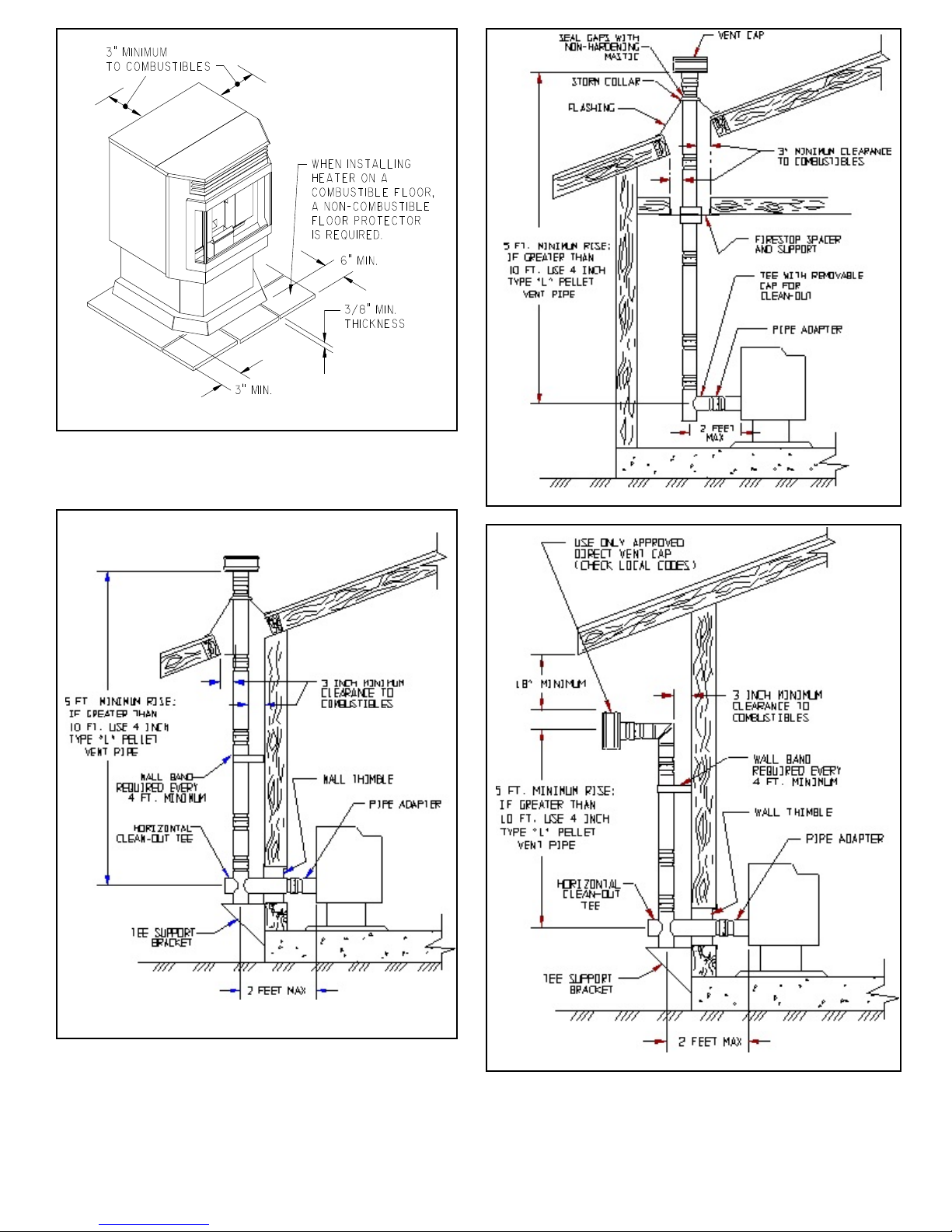
Figure 3
c. 2 ft. minimum to an adjacent building and 7 ft.
minimum above grade when located adjacent to
public walkways.
Figure 5
Figure 4
Figure 6
3
UNIT INSTALLATION
Route the power supply cord so that it does not touch
any of the exterior components of the heater.
1. When exiting through the wall with your type L Pellet
vent pipe, you may go straight out through a wall
thim ble. You m ust connect a pellet vent tee at this
point and extend the vent pipe at least 3' (three feet)
vertically outside to provide good draft and allow the
gases to exit. The tee must have a clean out cap for
inspection and regular cleaning (Figure 4). Horizontal
runs must be limited to 2' (two feet). A wall band is
required for every 4' (four feet) minimum on a vertical
run at an exterior wall.
2. All pellet vent pipe connections including exit at the
rear of the heater should be sealed with high
temperature silicone (450E) or m etallic duct tape. This
prevents smoke and soot leakage into the living area.
If this is not done, there is a possibility that the room
fan will pick up any leakage and blow it into the room.
AUTOLITE INSTALLATION INSTRUCTIONS
The AutoLite System is factory installed with the only
installation requirem ents being the optional therm ostat.
Wall Thermostat Installation:
The wall therm ostat is designed to autom atically regulate
the room temperature from the control panel heat setting
to the “Off” setting based upon room temperature.
Remem ber to leave the control panel on the "Medium or
High" position when utilizing the wall thermostat feature.
IMPORTANT - Any electrical work performed on the
EASYFIRE Heater should be done by qualified personnel.
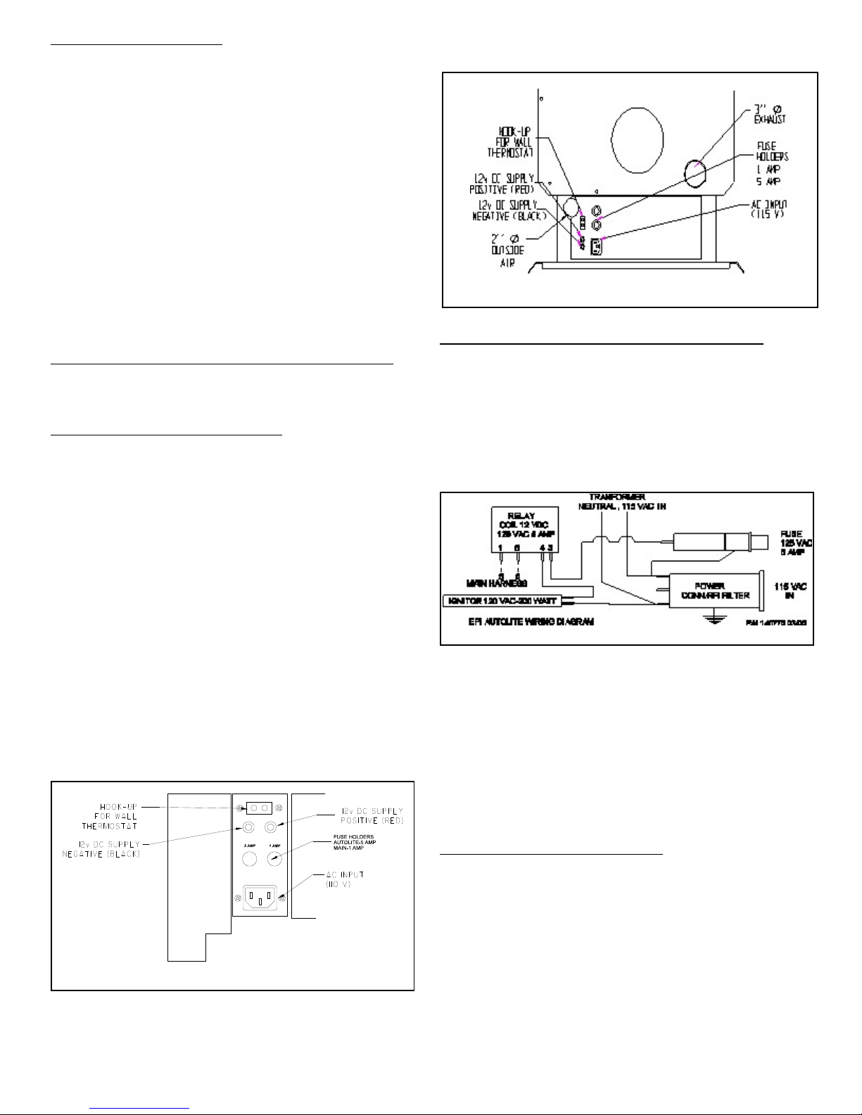
Figure 8 Stove Connection Panel
Remote Control Thermostat Installation:
The remote therm ostat is designed to automatically
regulate the room temperature from the control panel heat
setting to the “Off” setting based upon room temperature
and placem ent of the remote therm ostat. Rem ember to
leave the control panel on the "Medium or High" position
when utilizing the wall thermostat feature.
The following is a step by step procedure for installing the
optional remote thermostat. Note connection terminals on
rear of unit (Figure 1,2).
The following is a step by step procedure for installing the
optional wall thermostat. Note connection terminals on left
side of unit at rear (Figure 7,8). Use 18/2 therm ostat wire
for the installation.
a. Unplug heater from wall outlet and 12VDC power!
b. Remove factory jump wire and hook up thermostat
wires to terminals (Figure 7,8).
c. Locate thermostat approximately 10 to 12 feet from
heater or in area that requires steady temperature.
d. Run thermostat wires from heater to thermostat
along wall or under carpet etc. and hook wires to
thermostat terminals. On new construction you
can, of course, run wire in the walls before sheet
rock or paneling is done.
Autolite Wiring Diagram
a. Unplug heater from wall outlet and 12VDC power!
b. Mount millivolt style remote receiver box to rear of
stove using double-sided tape.
b . Remove factory jump wire and hook up thermostat
wires to terminals (Figure 7,8).
d. Reconnect AC power and follow instructions with
remote thermostat regarding set up.
IMPORTANT - Any electrical work performed on the
EASYF IRE Heate r should be done by qualified personnel.
DOOR HANDLE ASSEMBLY
The door handle and latch must be assembled and adjusted
prior to the operation of the stove.
1. Position handle assem bly through door and secure with
collar by sliding over shaft and tightening with allen
wrench provided (Figure 9).
Figure 7 Rear Connection Panel
e. Reconnect AC power.
f. Make sure all wiring is completed before plugging
the EASYFIRE Heater back into the wall outlet.
2. Position latch on end of shaft with flat facing allen screw.
Depending on gasket, shaft will protrude approx. 1/4"
through back of latch collar. Snug allen screw.
4
 Loading...