

Page 1
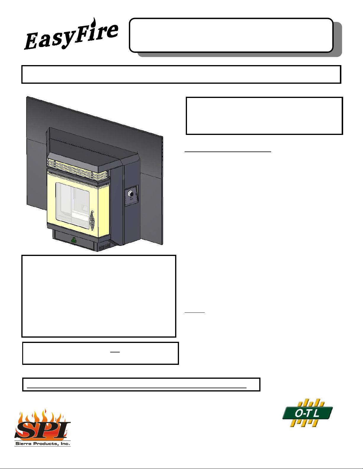
EF4001B AutoLite Pellet Stove Insert
Installation & Operating Instructions
Please read this entire manual before installation. Save these instructions.
PLEASE READ THIS ENTIRE MANUAL BEFORE INSTALLATION
AND USE OF THIS PELLET FUEL-BURNING ROOM HEATER.
FAILURE TO FOLLOW T HESE IN STRU CTION S COU LD RESU LT IN
PROPERTY DAMAGE, BODILY INJURY OR EVEN DEATH.
GENERAL INFORMATION
Installation and repair should be done by a qualified
service person. The heater should be inspected before use
and at least annually by a professional service person. More
frequent cleaning may be re quired due to f uel quality,
excess ive lint fr om carpetin g, beddin g m ate rial, etc . It is
impera tive that control compartm ents, burn pot and circulating air passageways of the heater be kept clean.
SAFETY NOTICE
< CAUTION: HOT WHILE IN OPERATION. KEEP CHILDREN,
CLOTHING AND FURNITURE AWAY. CONTACT MAY
CAUSE SKIN BURNS.
< IF THIS HEATER IS NOT PROPERLY INSTALLED,
A HOUSE FIRE MAY RESULT.
< CONTACT LOCAL BUILDING OFFICIALS ABOUT RE-
STRICTIONS AND INSTALLATION INSPECTION REQUIREMENTS IN YOUR AREA.
< FAILURE TO COMPLY WITH OWNERS' MANUAL IN-
STRUCTIONS WILL VOID YOUR WARRA NTY!
NOTE: This heater should not be installed in a
bedroom or bathroom.
The EASYFIRE Pellet Insert has been designed and
approved for burning wood pellet fu el on ly. Burning solid
fuel in other forms is not permitted and will void all warranties.
This unit has been approved for use with a Ø 3" Type L
Pellet Vent System or Stainless Chimney Liner (Ø 4" on
runs 10 feet and above).
NEVER use gasoline, gasoline-type lantern fuels,
kerosene, charcoal lighter fluid, or similar liquids to start or
"freshen up" a fire. Keep all such liquids well away from the
heater while it is in use.
Ashes must be disposed of in a metal container with a
tight fitting lid and placed on a noncombustible floor or
grou nd, well aw ay from all fuels, pe nding fina l disposa l.
NOTE : During the first few burns the high temperature
paint and sealant used in manufacture will emit some odor
and smoke. Open doors and windows to the outside for
proper ventilation during the first burn cycle and curing of
the paint.
This heater, w hen insta lled, must be electrically grounded in
accordance with local codes or, in the absence of local
codes, with the National Electrical Code, ANSI/NFPA 70-
2006.
INSTALLER: PLEASE LEAVE THIS MANUAL WITH THE OWNER!!
Sierra Products, Inc.
5061 Brooks St., Ste B
Montclair, CA 91763
(909) 399-3355
Listed by OMNI-Test
Laboratories, Inc.
Report No. 256-S-01-4
Page 2
Provide adequa te clearan ces around air openings into the
combustion chamber and adequate accessibility clearance for
servicing and proper operation. Never obstruct the front
opening of the heater.
Use only listed Type "L" pellet vent or stainless liner and
com ponents for installation. Failure to us e listed components
will void your warranty. See pipe manufacturer instructions for
installation instructions.
The heater may be installed as a free -standing unit m ounted on a noncombustible protective floor pad or he arth, o r it
may be m ounted into an existing U. L. approved wood stove
chimney using a Hearth Extension (p/n 11099). Non-combustible floor protection is required and must be used when
placin g the hea ter on an y combu stible m aterial.
The pellet heater must b e operated with a power source
and will not o perate u sing natural draft. If there is a power
failure the heater will shut down. If the 12 volt back-up system
is installed, th e heater will autom atic ally switch to 12 volt
power. An optional backup battery is available for the un it
which lasts approximately 48 hrs on high and 72 hrs on low.
A bigger battery may be purchased if desired for longer
durations.
The EasyFire Pellet Heater has been listed by OMNI-Test
Laboratories, Inc. to ASTM, U.L.,and EPA Standards.
CAUTION: Do not connect this unit to a chimney flue serving
another appliance.
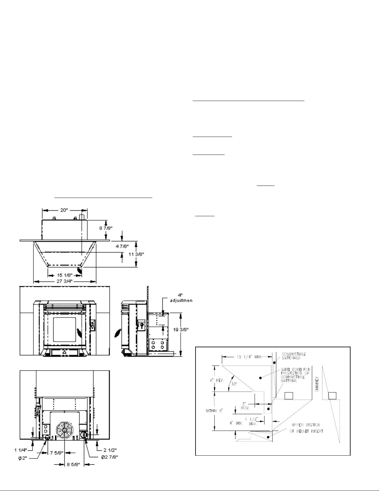
EF4100 Overall Dimensions
OUTSIDE CO MBUST ION AIR IS MAND ATO RY IN
MOBILE OR MO DULAR HOME INSTALLATIONS. SEE
SECTION ON OUTSIDE AIR INSTALLATION.
CAUTION: DO NOT CONNECT TO ANY AIR
DISTRIBUTION DUCT OR SYSTEM .
INSTALLATION INSTRUCTIONS
Check with local building officials for specific code
requirements.
A listed, type "L" Pellet V ent Pipe o r Stainles s Liner is
MANDATORY on all installations.
WARNING: Installation of a Mobile Attachment Home
Kit P/N 10412 and outside combustion air is mandatory
in mobile or modular home installations although it may
also be u sed in all residential applications.
An outside air inlet MUST be provided for
combustion and ven tilation air. The air inlet must
rem ain unre stricted w hile unit is in use. O uts ide air
connection is located in the rear of the heater (Figure 1).
NOTE: Vent Pipes’ inner diameters may vary.
For Vent Pipes Ø3.00" or smaller, use SPI Exhaust Vent
Adapter p/n 11076.
This adapter is used on Selkirk Metalbestos™ and other
Ø2.950" I.D. Pellet Vent Pipes.
Use conduit pipe or metal flex pipe and/or fittings to make
the air intake hook-up.
Also, the structural integrity of the mobile hom e floor,
walls and ceiling/roof must be maintained.
1. Clean and inspect the fireplace and its chimney for any
structural defect that may cause any future problems.
Secure gas piping that is installed with a cap and verify
there are no leaks. Seal ash dump or any other acc ess to
the firebox area. Fix the damper in an open position or
remove it as required for vent pipe installation.
2. Verify the required hearth and side and clearances to
mantels (fig. 2 & 3).
Figure 2
2
Page 3
NOTE: THE INSERT W EIGHT IS SUBSTANTIAULLY
FRONT H EAVY AND IF NOT FULLY SUPPOR TED IT
COULD FALL FORWARD.
Figure 5
Figure 3
3. If the hearth and fireplace floor are not at the same
elevation, leveling legs may be installed on the rear of the
unit (Figure 4) for distances of up to 1". For larger
distances shimming may be used using a non-co mbustib le
materia l. A Hearth Base Support is available from your
dealer for installations where the hearth is below the
fireplace opening (Figure 5).
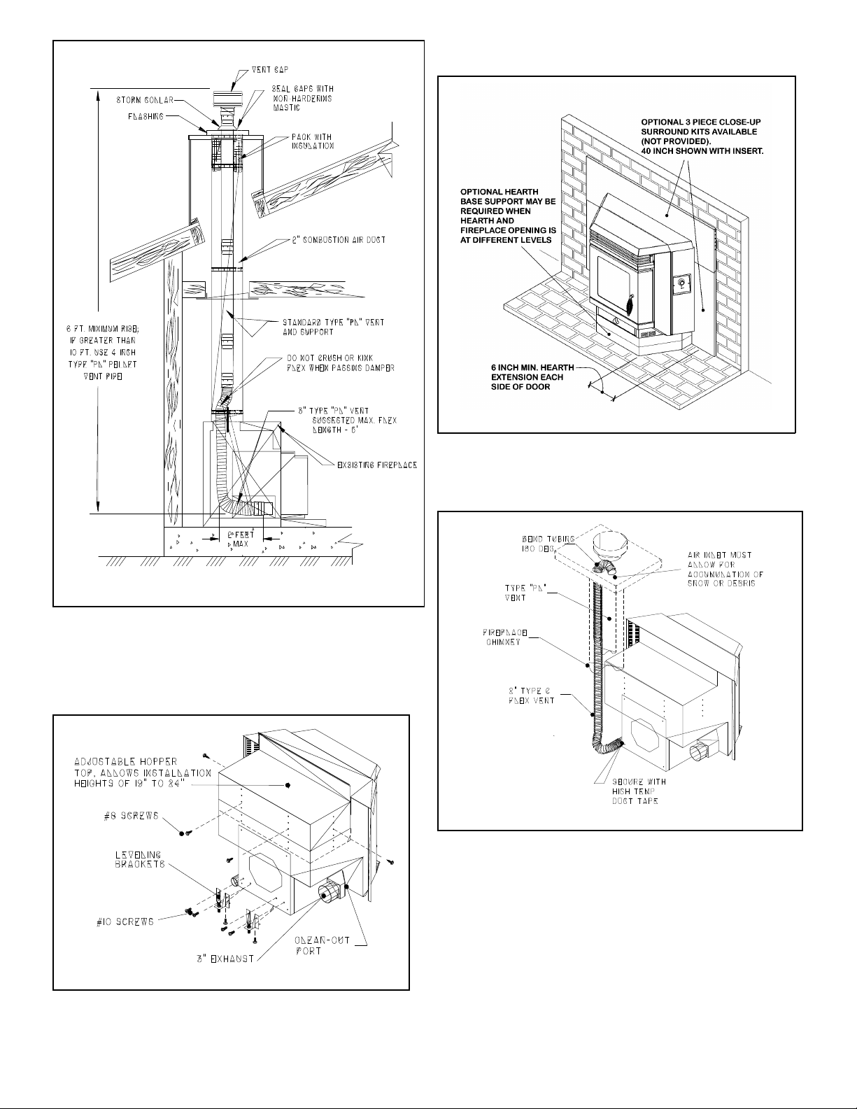
4. Ins tall vent system into existing chimney by using 3" flex
from left side of hearth, passing da mper and c ontinuing to
the top of the chimney. If the total vent length is longer than
10 Feet, install Ø4" vent from that point to top of chimney
(Figure 6).
Figure 6
Figure 4
5. Pack fiberglass insulation around the vent pipe and
combustion air duct. Install a flashing cover over
chimne y. Secure flashing a nd seal a s req uired. Ins tall
listed vent cap and secure.
6. Measure fireplace opening and adjust hopper top to the
required level allow ing for ins tallation cle arance . This is
accomplished by removing the four #8 screws on the sides
and rear of un it and raising the to p by 1" incr em ents until
desired height and reinstalling screws (Figure 4).
7. Slide insert into fireplace and center. Level as required,
then secure vent to outlet on left side of insert. Connect
combustion air duct and secure.
3
Page 4
Note - For best insert operation the flexible vent
installation should no t have any tight bends. Try to
achieve a smooth sweep to the vertical rise.
SURROUND INSTALLATION
The surroun d supplie d with the in sert is adjustable in
height so as to allow for many installation perimeters.
1. After the insert is in position, install left and right surround
sides by attaching them to the two side brackets using the
four 1/4-20 bolts provided. The retainer nuts on the
surround sides m ay be installed at any vertical position to
accommodate the installation.
2. Slide the surround top panel between the hopper top and
cover. Push the panel down until the screw holes align
with the side legs. Install the (4) #8 screws provided.
Install power cord into the receptacle on the right side of
the insert. Route cord behind surround leg and out to a
ground plus.
AUTOLITE INSTALLATION INSTRUCTIONS
The Auto Lite System is factory ins talled with th e only
installation requirem ents being the optional therm osta t.
IMPORTANT - Any electrical work performed on the
EASYFIRE H eater sh ould be d one by qualified personn el.
Remote Control Thermostat Installation:
The rem ote thermostat is designe d to autom atically
regulate the room temperature from the control panel heat
setting to the “Off” setting based upon room temperature
and place ment of the re mote therm osta t. Rem em ber to
leave the control panel on the "Medium or High" position
when utilizing the wall thermostat feature.
The following is a step by step procedure for installing the
optional remote thermostat. Note connection terminals on
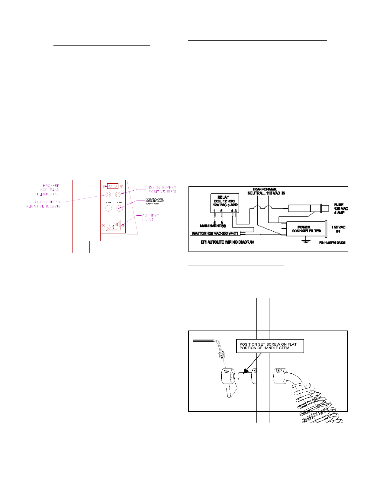
rear of un it (Figure 7).
a. Unplug heater from wall outlet and 12VDC power!
b. Mount millivolt style remote receiver box to rear of
stove using double-sided tape.
b. Rem ove factory jump wire and hook up thermostat
wires to terminals (Figure 7).
d. Re connect AC power and follow instructions with
remote thermostat regarding set up.
IMPORTANT - Any electrical work performed on the
EASYFIRE H eater sh ould be d one by qualified personn el.
Figure 7 Connection Panel Lower Right Side
Wall Thermostat Installation:
The wa ll therm ostat is designed to autom atically regulate
the room tem pera ture from the c ontrol panel heat setting to
the “Off” setting based upon room temperature. Remember
to leave the control panel on the "Medium or High" position
when utilizing the wall thermostat feature.
The following is a step by step procedure for installing the
optional wall thermostat. Note connection terminals on left
side of unit at rear (Figure 7). Use 18/2 thermostat wire for
the installation.
a. Unplug heater from wall outlet and 12VDC power!
b. Rem ove factory jump wire and hook up thermostat
wires to terminals (Figure 7).
c. Locate thermostat approximately 10 to 12 feet from
heater or in area that requires steady temperature.
d. Run thermostat wires from heater to thermostat along
wall or unde r carpet etc. and hook wires to
thermostat terminals. On new construction you can,
of course, run wire in the walls before sheet rock or
paneling is done.
e. Reconnect AC power.
f. Make sure all wiring is completed before plugging the
EASYF IRE Heater b ack into the wall ou tlet.
Autolite Wiring Diagram
DOOR HANDLE ASSEMBLY
The door handle and latch must be assembled and
adjusted prior to the operation of the stove.
1. Position handle assembly through door and s ecure with
collar by sliding over shaft and tightening with allen
wrench provided.
2. Position latch on end of shaft with flat facing allen screw.
Depending on gasket, shaft will protrude approx. 1/4"
through back of latch collar. Snug allen screw.
Figure 9 Door handle asse mbly
3. To adjust do or, close and turn handle so latch co ntacts
striker. Door gasket must contact firmly against front face
of unit. This can be checked by closing against a piece of
paper. Firmly tug on paper, if it m oves with solid
resistance the door is properly adjusted.
4
Page 5

UNIT ELECTRIC CONNECTIONS
Rou te the pow er supp ly cord from lower right side of unit
to a groun ded three pro ng 120V AC receptac le. C are should
be taken to make sure the fireplace and hearth does not
pinch or otherwise damage the cord.
OPTIONAL 12V HOOK-UP & OPERATION
1. The EASYFIRE 12V back up can be purchased as an
option and includes the following components:
a. Dee p cycle se aled 12V battery.
b. Battery connector cables for ho ok-up to the heater.
1. A chimney connector shall no pass through and attic or
roof space, closet or similar concealed spa ce, or a floor,
or ceiling.
2. W here a chimney passage through a wall, or partition of
combu stible con struction is desired, the insta llation sha ll
conform the CAN/CSA-B365.
3. Maintain an effective vapour barrier at the location where
the chimney or other component penetrates to the
exterior of the structure by sealing with high temperature
silicone.
4. Clearance to combustibles may only be reduced by
means approved by th e regulato ry au thority.
2. In order to hook-up the battery and engage the 12V
backup system simply connect red cable to red terminal
on the heater (see Figure 6) and to positive connector on
battery [the terminal marked (+)] and connect the black
cable to the black terminal on the heater and to the
negative connector on the battery (the terminal marked
(-). If you hook up the cables backwards the red LED
light above the term inal receptacles will come on. If
hooked up properly this LED will glow green.
WARNING - MAKE SURE RED CABLE GOES TO RED
TERMINAL (POSITIVE CONNECTOR) AND BLACK
CABLE GOES TO BLACK TERM INAL (NEGATIVE
CONN ECTOR).
3. If you decide to purchase your own 12V back up system
we recom mend a sealed gel cell b attery. Failure to insta ll
the proper battery could cause physical harm to you and
your property an d will also void the heater w arranty.
4. When the battery is properly connected and the heater
plugg ed in, the follow ing will hap pen auto matically:
a. The heater w ill automatically s witch to 12V p ower if
there is a power failure, and switch back when power
is restored.
b. The battery will be trickle charged as long as the
heater is plugged into 110 AC wall outlet. Do not use
extension cords. The trickle charge will not recharge
a low or dead battery but it will keep a charged
battery at maximum performance.
5. If you choose to separate the battery from the heater by
lengthening the cables you must make sure that the
cable wire used will carry the current to the heater. For
example, if the distance is 10 to 20 feet then 12 gauge
wire must be used. Check with your local electrical
professional to make sure you have used the proper
gauge wire/cable.
a. Unplug heater from wall outlet and 12VDC power!
b. Mount millivolt style remote receiver box to rear of
stove using double-sided tape.
b. Rem ove factory jump wire and hook up thermostat
wires to terminals (Figure 7).
d. Re connect AC power and follow instructions with
remote thermostat regarding set up.
CANADIAN REQUIREMENTS
If this unit is being installed in Canada, the following
additional req uirem ents must b e m eant:
5. Store pellet fuels in a dry area away from unit. Do not
store fuels within the space heater installation clearances
or within the space required for charging and ash
rem oval.
6. Adequate ventilation air is required to operate this heater.
During operation the heater draws air for combustion
which can be assisted by the installation of outside
combustion air inlets. However, certain weather
conditions such as icing or use of kitchen exhaust fans
may impact a nd reduce th e effectiv eness o f vents. It is
importa nt to note th at room air starva tion well ne gatively
impact the operation of the heater.
7. If power outages with batter y backup or room air
starvation occurs during operation of hea ter, smoke in
the house may result. This may trigger smoke de tectors
if they are installed .
AUTOLITE OPERATION
Your EA SYFIRE Pellet S tove is equ ipped with the Au tolite
Automatic ignition and operating system.
The AutoLite system is integrated into the stove to allow for
automatic start up using a heating element located in the
burn pot. This element starts the initial fire required to burn
the wood pellets. The system operates on 120VAC power
supplied through a separate fuse and runs for five minutes
during the initial stove start up. After the five minute period
the AutoLite system is deactivated and the stove operates
based on the EasyFire digital control system requirements.
If the h ouse AC po wer should qu it, the Auto Lite system will
not be available however, with the optional battery attached
the stove can be manually lit and operate on battery power
for several days (depending on battery size, refer to the
EasyFire installation manual).
The m ost e ffective installation of the EasyFire AutoLite
Stove is to connect the unit to a thermostat. This can be
accomplishe d using a stand ard wall thermostat or a re mote
control thermostat. A remote control thermostat can be
purchased from your local dealer and installed in a few
minutes. This will allow the stove to start and shut down
when there is a call for heat.
If your house power is out the AutoLite system will not be
able to start the stove when the therm ostat calls for hea t.
However if the stove is operating when the power goes out
the stove will not shut down operating on the backup
battery. Your EasyFire will turn down to low when the
thermostat calls for shut down and then turn up to the
setting on the control panel when the thermostat calls for
heat. A true back up heat source!
5
Page 6

GENERAL WARNINGS
The EASYFIRE Pellet Stove and Insert has been
designed and approved for burning wood pellet fuel only.
Burning solid fu el in other forms is not perm itted and will
void all warranties.
NEVER use gasoline, gasoline-type lantern fuels,
kerosene, charcoal lighter fluid, or similar liquids to start or
"freshen up" a fire. Keep all such liquids well away from the
heater while it is in use.
Ashes must be disposed of in a metal container with a
tight fitting lid and placed on a noncombustible floor or
grou nd, well aw ay from all fuels, pe nding fina l disposa l.
This heater, w hen insta lled, must be electrically grounded in
accordance with local codes or, in the absence of local
codes, with the National Electrical Code, ANSI/NFPA 70-
2006.
Provide adequate clearances around air openings into the
combustion chamber and adequate accessibility clearance for
servicing and proper operation. Never obstruct the front
opening of the heater.
The pellet heater must be operated with a power source
and will not operate using natural draft. If there is a power
failure the heater will shut down. If the 12 volt back-up system
is installed, the heater w ill autom atically switc h to 12 vo lt
power. An optional backup ba ttery is available fo r the unit
which lasts appro xim ately 48 hrs on high and 72 hrs on low.
A bigger battery may be purchased if desired for longer
durations.
The EasyFire Pellet Heater has been listed by OMNI-Test
Laboratories, Inc. to ASTM, U.L.,and EPA Standards.
FUEL SELECTION
Proper fuel se lection is im po rtant for overall operation. Your
stove operates best with 1/4" diameter wood pellets that are
no longer than 3/4" long. The pellets shou ld be specifica lly
manufactured for use pellet heaters. Use of fuel nonconforming fuel will cause the stove to opera te erratica lly.
Additiona lly, a low ash content o f below 1% is required and
will reduce your cleaning and maintenance time. Store pe llets
in a clean dry area. Do not use pellets that have been damp
or have a moisture level above 5%.
The quality of pellet fuel varies fro m brand to brand. T his will
affect the efficiency of your heater. We suggest that you try
several brands until you find one th at gives you a cle an efficient burn. Poor quality pellets will burn rich with black soot
and ash w ill accumula te quickly. Quality pellets will burn clean
and ash build u p will be m inim al.
attempt to operate heater if glass becomes damaged in any
way!
2. AutoLite Control Functions: Control functions on the
Easyfire are as follows: OFF, FAN, LOW, MEDIUM, HIGH,
CLEAN. Here is how each function works:
A. When the Control Button is turned to FAN, a tim er is
activated a nd you will have about ten (10) minutes to
get the pellets lit and reach a minimum temperature.
This function is used for match lighting when the AC
power is out.
Should the pellets not light in 10 minutes simply turn the
button to OFF and begin again. This will give you
another 10 minutes to get the pellets lit. The reason for
the timer function is so that the heater will autom atically
shut down if the fire goes out. Pellets do not feed in the
FAN position.
B. In the LOW position, the EASYFIRE will be feeding
approximately 1 to 1½ lbs. of pellets per hour and the
flame will fluctuate between 1 " and 6" in height.
AUTOLITE START-UP AND OPERATION
Refer to Installation and Operation manual provided with
the unit for standard match lighting and 12V operations.
1. AutoLite Start-Up:
Prior to operating your AutoLite stove, make sure the
hopper is full of wood pellets and the interio r com ponents
have be en installed properly including; burn screen & pot,
heat exchange co vers, and ash drawer.
IMPORTANT: The Fire Pot must be seated flush and
must sit even in the pot tray. Air leaking around the Fire Pot
will create a poor burn (Figure 11). Light the pellets in Fire
Pot using any approved pellet lighter.
Note: Caution must be taken when installing burn pot or
operating door not to damage ceramic glass. Do not
Figure 11
6
Page 7

C. In the MEDIUM position the EASYFIRE will be
feeding approximately three (3) pounds of pellets per
hour and the flame will fluctuate between 3" and 8" of
fire.
WARNING: Risk of electrical shock, disconnect all AC/DC
power before servicing.
ALWAYS TURN YOUR Heater OFF & LET IT COOL
BEFORE CLEANING.
D. In the HIGH position the EASYFIRE will be feeding
approximately 4+ lbs. pe r ho ur an d the flame w ill
fluctuate between 3" and a full flame. The fan speed
will incr ease ac cordingly as the heater au tom atically
adjusts itself based on temperature inside the heater
(see G below).
E. The CLEAN position is to be used only when the
heater is not burning and you wish to clean out the
accumulated ash in the front of the fire area. See
CLEAN OUT section of maintenance instructions.
F. After the heater is running for several hours and you
wish to turn it off simply press the button to OFF. The
heater will continue running until it cools down
and then will automatically shut itself down.
G. REMEMBER: Each fee d position will fluctuate
because the microproce ssor is automatic ally
adjusting the feed and air based on tem perature. This
means the pellet feed ra te a nd flame height w ill
change accordingly based on quality of pellet and
heat loss of dwelling.
3. Starting the Stove: Push a Heat Range button (Low or
Medium is best for start up) and tu rn the thermostat up to
“Call for heat”. The sto ve fan will begin to operate along with
the ignitor cycle. A fter about a m inu te the pelle ts will begin
to fall in the burn pot. A fter five m inutes there will be a fire in
the burn pot and the stove will begin to heat up. When the
stove reaches start up operating temperature it will then
switch to th e contro l panel setting and begin it’s autom atic
operation cycle.
Prior to sto ve operating on thermosta t, confirm proper operation by
servicing and adjustin g the stove a s outlined in the “Installation
Guide”. When servicing stove, operate with thermostat bypassed as
stove will reset to start up mode each time thermostat is activated.
Feed Trim Adjustment
Your EASYFIRE Pellet Heater requires routine
maintenance for m aximum performance and is mandatory
for the warranty to remain in e ffect.
The following procedures should be studied carefully and
performed regularly as indicated:
1. Fly-ash: Some ash will accumulate in the heat
exchanger, Fire Pot and flue and should be cleaned out
on a regu lar basis for best efficiency and safety. When
the heater is shut down and cold, you should:
a. Open door and remove Heat Exchanger Cover. To
rem ove, sim ply slide up and out f rom retaining angle
bracket (Figure 12). Clean on e side at a time. With
one slide c over removed, leave door open and turn
control button to the "CLEAN" position. Let heater
run until ash in Fire Pot area is vacuumed out by
heater fan. Turn off and replace cover. Remove
remaining cover and repeat procedure for the other
side. The vent pipe should be clea ned out a fter this
procedure. Rem ove the clean-out port cover (Figure
13) and vacuum as required.
b. Rem ove Fire Pot by lifting up and out, it may be
brushed out or vacuumed. Fire Pot should be
cleaned weekly an d depending o n pellet qu ality daily.
Make sure holes in pot are not clogged. The area
around and below the pot shou ld be checked every
five or six days depending on how many hours a day
you are burning your heater and the quality of the
pellets being burned. (After a few days you will be
able to determine the frequency needed for clean
out.)
The importa nt thing to r em em be r is tha t excessive Flyash accumulation will affect the efficiency of the burn.
c. Scrape pellet feed chute with putty knife to remove
hardened material on which sawdust can
accumulate.
Underneath the control button you will find a small round
button that will turn forward and reverse. This button can
adjust the feed motor in the LOW operating position. By
turning the button clockwise you can increase the feed on
LOW and by turning it counterclockwise you can decrease
the feed in the LOW position. Factory setting is 1:00
o’clock.
Once the stove is at operating temperature for one hour
set the stove on LOW. Adjust the trim button so that
averag e flam e is approx. 1-2" abo ve the burn pot. T his
will set the average feed rate (air/flue) for best
operation.
Move this button carefully! It is designed to fine tune
your LOW setting in the even t you change brands of pellets
and/or live at a higher elevation. If this setting is to low the
stove m ay go out during LO W setting operations . If this
should happen increas e the trim by sm all amount.
MAINTENANCE PROCEDURE
CAUTION: Moving parts may cause injury, DO NOT
operate with rear cover removed.
d. The clean-out port cover should be removed and the
vent pipe checked every four to six weeks or
whenever you utilize the clean-out mode on the
control dial.
e. Fly-ash can also accumulate in the vent pipe and
termination cap . Inspect e xhaust system frequently to
maintain free flow of exhaust fumes and fly-ash. The
frequen cy of clean-out depends entirely on the quality
of the pellets, so you will have to initially monitor the
buildup in the pellet vent pipe.
2. Hopper Clean Out: Vacuum the accumulated saw dust
in the hopper weekly. Keep free of debris and foreign
material. AN ACCUMULATION OF SAW DUST CAN
CAUSE IRREGU LAR PEL LET F EED. For be st results
this should be done on a regular basis depending upon
how often the h eater is u sed. If you burn the heate r all
the time you should do this every eight to ten days.
3. Cleaning the E xhaust Fan Blade & Heat Exchanger:
The exhaus t blower s hould be chec ke d for excess ive Fly-
ash buildup. Regular and routine maintenance utilizing
the CLEAN OUT feature will keep the exhaust blower
housing and fan blades clean. This cleaning can only be
done wh en the heater is NOT burning. For bes t results
7
Page 8

run the fan in the CLEAN OUT position with the door open
for approximately one minute or until ash is no longer being
picked up by the fan. Remember, you must always check
the clean out cap on the tee after utilizing the CLEAN OUT
feature.
4. Keeping the Glass Clean: If soot deposits accum ulate
on the glass, clean with window glass cleaner and a
paper towel when the glass is cold.
5. Polishing the Gold and Nickel: All chrom e a nd gold
plating used on the EASYFIRE heater can be cleaned
with a soft cloth and non-abrasive cleaner.
6. Cleaning & Polishing Gold and Nickel Plated Parts:
Gold and Nickel is a soft m etal and th eref ore a fragile
surface. Prior to the first burn it is important to use
W index or c om parable product and a s oft clean c loth to
wipe any m arks off all gold su rfaces or the hea t will
cause th e m arks to rem ain in the s urfa ce perm an ently.
Always clean the gold surface when the heater is COOL.
7. Door glass replaceme nt: Should the door glass
become broken it may be replaced by scraping the sealer
from around the ou ter edge of the glass. Carefully pry
glass from door frame then clean all sealer from frame.
Obtain a replacement glass from your local dealer and
attach glass to door using High Temperature Silicon
Sealer (min. 400 / F). Apply sealer to all four corners of
the glass and set glass into frame. Apply sealer to mating
edge of glass and fram e. Allow two hours dry time before
installing doo r onto heater. Note: Replace with Corning
Pyro-Ceramic Glass only. Refer to parts list for
specifications.
Troubleshooting Guide
The following scenarios are provided in order to help you
locate a difficulty if the heater performs in a manner which
would seem to indicate a malfunction:
l. Problem: I loaded the heater for start-up, pressed the
button and pellets started but the fire didn't keep going.
Solution: Remember that the timer on start up runs
about 10 minutes and if the heater has not heated up
enough to deactivate the timer you will have to start over
by pressing the button to off and then back to MEDIUM
or HIGH.
EASYFIRE will automatically switch to 12 volt provided you have
the 12 volt battery option installed.
2. Problem: The heater was lit and burning properly, then
suddenly it stopped feeding pellets.
Solution: a) The thermostat setting is to low and the has
called for the stove to shu t down. b) Check pelle t supply
in hopper. If empty, fill and follow start-up procedure as
outlined in the be ginning o f this manua l. c) O ccasion ally,
a foreign object, debris or an excessive amount of sawdust can enter the feed mechanism and jam the feed
chute. If this happens, you must empty the hopper and
check the feed chute to see what is causing the jam.
Remove any foreign material or object and re-start the
heater. CAUTION: Keep fingers and hands clear of feed
mechanism when heater is on.
3. Problem: The fire was burning we ll and then it began to
overfeed pellets and started backing up into the pellet
feed chute, smothering the fire.
Solution: When th e pellets a re overfeeding, it us ually
means that the air flow has been red uced. Check the Fire
Pot air intak e holes to be sure they are c lear. Check to
see if Fire Pot was properly se ated in pot tray. Check to
see if the manifold may have filled with Fly-ash. If you
use a low grade pellet, and clink ers (fused ash and d irt)
form in th e bottom of the Fir e Pot, it will choke the air
intake (you might consider changing the brand of p ellets
to one that burns cleaner). You must let the fire go out
before removing and cleaning the Fire P ot.
Neve r vacuum out the heater when the heater is in
operation! The hot ashes can lodge in your vacuum
cleaner and cause a fire!
You must clean the manifold regularly in order to insure a
good air to fuel ratio, thus allowing the heater to "breathe"
properly. You must also check the vent pipe and tee to see
that they are not clogged and full of ash.
4. Problem: Heater was burning well and then soot began
forming on the glass door.
Solution: Black soot forming on the glass door means
that the combustion is not right and the heater needs a
good clean out. Some brands of pellets burn much richer
than others and you might have to change brands of
pellets and/or have the air/fuel settings re-adjusted by
your dealer. It is normal to have the glass cloud up after
several hours of burning but it should wipe off with a
good window c leaner. If t he glass turns black quick ly,
then the h eater needs a good clea n out.
5. Problem: W e had a power failure and the heater
emitted smoke for about five minutes.
Solution: If the heater emits smoke during a power
failure, and you have frequent power failures then we
suggest you purchase the battery back-up system. If the
vent pipe is installed according to these instructions the
smoke will syphon out of the pipe in most instances.
6. Problem: After several weeks of outstanding perfor-
mance, the heater suddenly stopped and the red light
under the control button came on. This light is the Hi
Tem p/Flue Indicator Light.
Solution: The Hi-Temp/Flue Indicator light indicates that
Fly-as h has bu ilt up in the e xhaust s ystem and/o r there is
a restriction in the exhaust/flue system. Check the pipe
system for excessive ash and clogging, particularly the
vent cap. Remove the clean out cap on the tee and
make sure that ash has not blocked the exhaust air flow.
This automatic shut down in case of flue clogging is a
safety feature and if the shut down occurs it means you
have a problem and should consult a service technician
and/or clean your pipe and heater thoroughly. If you feel
the Fly-ash build up is excessive, we suggest that you try
another brand. In moist climates the pellets and Fly-ash
can actually absorb moisture from the a ir and crea te
creo sote and a severe clog ging problem . Ke ep this in
mind when you store and handle your pellets. The heater
warranty does not cover the quality of the fuels used or
the way they may be handled either before or after you've
purchased them.
7. Problem: I turned off the switch and the heater kept
running.
Solution: This is normal. The exhaust blower will keep
runn ing until it cools down and th en it will auto m atically
turn off. This can vary by the temperature the exhaust
has reached and the temperature of the cooling air.
8
Page 9

HI TEMP/FLUE AND TRIM INDICATORS:
W hen the Hi-Temp/Flue indicator light com es o n (red lite
beneath control button) it means that the flue is obstructed
or you have a re vers e draft and ga ses can not exit properly.
Maintenance is required and a thorough cleaning and pipe
check must be performed.
TRIM button : Underneath the control button you will find a
sm all round b utton that will turn forward and reverse. This
button ca n control the feed m oto r in th e LOW po sition only.
By turning the button clockwise you can increase the feed
on LOW and by turning it counterclockwise you can
decrease the feed in the LOW position.
Move this button carefully! It is designed to fine tune
your LOW setting in the even t you change brands of pellets
and/or live at a higher elevation.
DC OPERATION - BUILDING A FIRE AND
START-UP
IMPORTANT (Gold Units Only): Gold is a soft metal and
therefore a fragile su rface. Pr ior to the fir st burn it is important
to use Windex™ or comparable product with a soft clean cloth
to wipe any marks off all gold surfaces.
If not cleaned prior to first burn, the heat may cause the marks
to rem ain in th e surface pe rm anently.
Always clean the gold surface when the heater is COOL.
1. Filling the Hopper and Start-Up:
CAUTION: Fuel hopper lid must be closed before
operating unit. Maintain hopper seal in good condition.
DO NOT OVERFILL HOPPER! The EASYFIRE will hold
about 35 lbs. to 50 lbs. of pellets depending on hopper
height.
Open the top lid and fill the hopper with pellets (Figure 9).
The quality of pellet fuel varies from bra nd to brand. T his
will affect the efficiency of your heater. W e suggest that you
try several brands until you find one that gives you a clean efficient burn. Poor quality pellets will burn rich with black soot
and ash will accum ulate quickly. Quality pellets will burn clean
and ash build u p will be m inim al.
Make sure hopper lid is fully closed. Open the front door.
Fill the Fire Pot with pe llet fue l.
IMPORTANT: The Fire Pot must be seated flush and
must sit even in the pot tray. Air leaking around the Fire Pot
will create a poor burn (Figure 10). Light the pellets in Fire
Pot using any approved lighter fluid.
Figure 12
Allow pellets to burn for ap proxim ately 1 minute, o r un til
pellet ignition ha s been achieved. Close door and turn the
control knob to the "FAN" position. Allow fire to burn for
several minutes. When the pellets are well lit, turn the
control knob to "LOW" for approximately 10 minutes then
turn up to "HI". We recomm end that you run the heater on
“Medium” or "HI" for about 30 minutes in order to get the
heat exc hanger hot be fore turning it to "LO W ". Yo u will
need to burn the heater for a few hours before deciding
which setting is best for your particular needs.
Figure 13
9
Page 10

Note: Caution must be taken when installing burn pot
or operating door not to damage ceramic glass. Do not
attem pt to operate heater if glass becomes d am aged in
any way!
2. Control Functions: Control functions on the Easyfire
are as follows: OFF, FAN, LOW, MEDIUM, HIGH, CLEAN.
Here is how each function works:
ALWAYS TURN YOUR Heater OFF & LET IT COOL
BEFORE CLEANING.
Your EASYFIRE Pellet Heater requires routine
maintenance for m aximum performance and is mandatory
for the warranty to remain in e ffect.
The following procedures should be studied carefully and
performed regularly as indicated:
A. When the Control is set to FAN, a timer is activated
and you will have about ten (10) minutes to get the
pellets lit and rea ch a minim um temperature.
Should the pellets not light in the 10 minutes simply turn
the knob to OFF and begin again. This will give you
another 10 minutes to get the pellets lit. The reason for
the timer function is so that the heater will autom atically
shut down if the fire goes out. Pellets do not feed in the
FAN position.
B. In the LOW position, the EASYFIRE will be feeding
approximately 1 to 1½ lbs. of pellets per hour and the
flame will fluctuate between 1 " and 6" in height.
C. In the MEDIUM position the EASYFIRE will be
feeding approximately three (3) pounds of pellets per
hour and the flame will fluctuate between 3" and 8" of
fire.
D. In the HIGH position the EASYFIRE will be feeding
approximately 4 lbs. per hour and the fla m e will
fluctuate between 3" and a full flame. The fan speed
will incr ease ac cordingly as the heater au tom atically
adjusts itself based on temperature inside the heater
(see G below).
1. Fly-ash: Some ash will accumulate in the heat
exchanger, Fire Pot and flue and should be cleaned out
on a regu lar basis for best efficiency and safety. When
the heater is shut down and cold, you should:
a. Open door and remove Heat Exchanger Cover. To
rem ove, sim ply slide up and out f rom retaining angle
bracket (Figure 12). Clean on e side at a time. With
one slide c over removed, leave door open and turn
control knob to the "CLEAN" position. Let heater run
E. The CLEAN position is to be used only when the
heater is not burning and you wish to clean out the
accumulated ash in the front of the fire area. See
CLEAN OUT section of maintenance instructions.
F. After the heater is running for several hours and you
wish to turn it off simply turn the knob to OFF. The
heater will continue running until it cools down
and then will automatically shut itself down.
G. REMEMBER: Each fee d position will fluctuate
because the microproce ssor is automatic ally
adjusting the feed and air based on tem perature. This
means the pellet feed ra te a nd flame height w ill
change accordingly based on quality of pellet and
heat loss of dwelling.
MAINTENANCE PROCEDURE
CAUTION: Moving parts may cause injury, DO NOT
operate with rear cover removed.
WARNING: Risk of electrical shock, disconnect all power
before servicing.
Figure 14
until ash in Fire Pot area is vacuumed out by heater
fan. Turn off and replace cover. Remove remaining
cover and repeat procedure for the other side. The
vent pipe should be cleaned out after this procedure.
Remove the clean-out port cover (Figure 13) and
vacuum as require d.
b. Rem ove Fire Pot by lifting up and out, it may be
brushed out or vacuumed. Fire Pot should be
cleaned daily. Make sure holes in pot are not
clogged. The area aro und and below the pot shou ld
be checked every five or six days depending on how
many hours a day you are burning your heater and
the quality of the pellets being burned. (After a few
days you will be able to determine the frequency
needed for clean out.)
The importa nt thing to r em em be r is tha t excessive Flyash accumulation will affect the efficiency of the burn.
c. Scrape pellet feed chute with putty knife to remove
hardened material on which sawdust can
accumulate.
10
Page 11

3. Cleaning the E xhaust Fan Blade & Heat Exchanger:
The exhaus t blower s hould be chec ke d for excess ive Fly-
ash buildup. Regular and routine maintenance utilizing
the CLEAN OUT feature will keep the exhaust blower
housing and fan blades clean. This cleaning can only be
done wh en the heater is NOT burning. For bes t results
run the fan in the CLEAN OUT position with the door
open for approximately one minute or until ash is no
longer being picked up by the fan. Remember, you must
always check the clean out tee after utilizing the CLEAN
OUT feature (Figure 13).
4. Keeping the Glass Clean: If soot deposits accum ulate
on the glass, clean with window glass cleaner and a
paper towel when the glass is cold.
5. Polishing the Gold and Chrome: All chrom e and gold
plating used on the EASYFIRE heater can be cleaned
with a soft cloth and non-abrasive cleaner.
Figure 15
d. The clean-out port cover should be removed and the
vent pipe checked every four to six weeks or
whenever you utilize the clean-out mode on the
control dial.
e. Fly-ash can also accumulate in the vent pipe and
termination cap . Inspect e xhaust system frequently to
maintain free flow of exhaust fumes and fly-ash. The
frequen cy of clean-out depends entirely on the quality
of the pellets, so you will have to initially monitor the
buildup in the pellet vent pipe.
2. Hopper Clean Out: Vacuum the accumulated saw dust
in the hopper weekly. Keep free of debris and foreign
material. AN ACCUMULATION OF SAW DUST CAN
CAUSE IRREGULAR PELLET FEED. For be st results
this should be done on a regular basis depending upon
how often the h eater is used. If you burn the heate r all
the time you should do this every eight to ten days.
Front ash access panel
6. Cleaning & Polishing Gold Plated Parts: Gold is a soft
metal and therefore a fragile surface. Prior to the first
burn it is important to use Windex or comparable product
and a soft clea n cloth to w ipe any m arks off all gold
surfaces or the heat will cause the marks to remain in the
surface permanently. Always clean the gold surface
when the heater is COOL.
7. Door glass replaceme nt: Should the door glass
become broken it may be replaced by scraping the sealer
from around the ou ter edge of the glass. Carefully pry
glass from door frame then clean all sealer from frame.
Obtain a replacement glass from your local dealer and
attach glass to door using High Temperature Silicon
Sealer (min. 400 / F). Apply sealer to all four corners of
the glass and set glass into frame. Apply sealer to mating
edge of glass and fram e. Allow two hours dry time before
installing doo r onto heater. Note: Replace with Corning
Pyro-Ceramic Glass only. Refer to parts list for
specifications.
8. Plenum clean out & draft adju stment: Access to clean
under the burn pot is through the plenum clean out plates
on right or left side low front (Figure 16). Remove the
fastener and plate and vacuum out ash accumulations.
Additiona lly, the draft p late is acc essible th rough th is
opening and maybe turned with a long standard screw
driver clockwise to reduce the draf t through th e burn pot.
This adjustment is made generally only during
installation.
Figure 16 Plenum Clean Out & Draft Adjustment
Troubleshooting Guide
The following scenarios are provided in order to help you
locate a difficulty if the heater performs in a manner which
would seem to indicate a malfunction:
l. Problem: I loaded the heater for start-up, lit the fire
starter and pellets but the fire didn't keep going.
Solution: Check power cord to s ee that it is plugg ed in.
Remember that the timer on start up runs about 10
minutes and if the heater h as not heated up enou gh to
11
Page 12

deactivate the timer you will have to start over by turning the
knob to off and then back to FAN or LOW.
vent pipe is installed according to these instructions the
smoke will syphon out of the pipe in most instances.
The EASYFIRE will automatically switch to 12 volt backup
provided you have the 12 volt option installed.
2. Problem: The heater was lit and burning properly, then
suddenly it stopped feeding pellets.
Solution: a) Check pellet sup ply in hopper. If e mpty, fill
and follow start-up procedure as outlined in the beginning
of this manual. b) O cc asionally, a foreign object, debris
or an excessive amount of sawdust can enter the feed
mechanism and jam the feed chute. If this happens, you
must empty the hopper and check the feed chute to see
what is causing the jam. Remove any foreign material or
object an d re-start the heater. CAUTION: Keep fingers
and hands clear of feed mechanism when heater is on.
3. Problem: The fire was burning we ll and then it began to
overfeed pellets and started backing up into the pellet
feed chute, smothering the fire.
Solution: When th e pellets a re overfeeding, it us ually
means that the air flow has been red uced. Check the Fire
Pot air intak e holes to be sure they are c lear. Check to
see if Fire Pot was properly se ated in pot tray. Check to
see if the manifold may have filled with Fly-ash. If you
use a low grade pellet, and clink ers (fused ash and d irt)
form in th e bottom of the Fir e Pot, it will choke the air
intake (you might consider changing the brand of p ellets
to one that burns cleaner). You must let the fire go out
before removing and cleaning the Fire P ot.
Neve r vacuum out the heater when the heater is in
operation! The hot ashes can lodge in your vacuum
cleaner and cause a fire!
You must clean the manifold regularly in order to insure a
good air to fuel ratio, thus allowing the heater to "breathe"
properly. You must also check the vent pipe and tee to see
that they are not clogged and full of ash.
6. Problem: After several weeks of outstanding perfor-
mance, the heater suddenly stopped and the red light
under the control knob came on. This light is the Hi
Tem p/Flue Indicator Light.
Solution: The Hi-Temp/Flue Indicator light indicates that
Fly-as h has bu ilt up in the e xhaust s ystem and/o r there is
a restriction in the exhaust/flue system. Check the pipe
system for excessive ash and clogging, particularly the
vent cap. Remove the clean out cap on the tee and
make sure that ash has not blocked the exhaust air flow.
This automatic shut down in case of flue clogging is a
safety feature and if the shut down occurs it means you
have a problem and should consult a service technician
and/or clean your pipe and heater thoroughly. If you feel
the Fly-ash build up is excessive, we suggest that you try
another brand. In moist climates the pellets and Fly-ash
can actually absorb moisture from the a ir and crea te
creo sote and a severe clog ging problem . Ke ep this in
mind when you store and handle your pellets. The heater
warranty does not cover the quality of the fuels used or
the way they may be handled either before or after you've
purchased them.
7. Problem: I turned off the switch and the heater kept
running.
Solution: This is normal. The exhaust blower will keep
runn ing until it cools down and th en it will auto m atically
turn off. This can vary by the temperature the exhaust
has reached and the temperature of the cooling air.
HI TEMP/FLUE AND TRIM INDICATORS:
W hen the Hi-Temp/Flue indicator light com es o n (red lite
beneath control knob) it means that the flue is obstructed or
you have a reve rse draft and gases cannot exit prop erly.
Maintenance is required and a thorough cleaning and pipe
check must be performed.
4. Problem: Heater was burning well and then soot began
forming on the glass door.
Solution: Black soot forming on the glass door means
that the combustion is not right and the heater needs a
good clean out. Some brands of pellets burn much richer
than others and you might have to change brands of
pellets and/or have the air/fuel settings re-adjusted by
your dealer. It is normal to have the glass cloud up after
several hours of burning but it should wipe off with a
good window c leaner. If t he glass turns black quick ly,
then the h eater needs a good clea n out.
5. Problem: W e had a power failure and the heater
emitted smoke for about five minutes.
Solution: If the heater emits smoke during a power
failure, and you have frequent power failures then we
suggest you purchase the battery back-up system. If the
TRIM button : Underneath the control knob you will find a
sm all round b utton that will turn forward and reverse. This
button ca n control the feed m oto r in th e LOW po sition only.
By turning the button clockwise you can increase the feed
on LOW and by turning it counterclockwise you can
decrease the feed in the LOW position.
Move this button carefully! It is designed to fine tune
your LOW setting in the even t you change brands of pellets
and/or live at a higher elevation.
12
Page 13

ITEM No. PART NUMBER DESCRIPTION
1 110429 DOOR FRONT GLASS (Ceramic glass 11"x11 3/4"x5mm)
2 100119 GLASS FIBER GASKET
3 100125 DOOR FIBER ROPE GASKET
4 300536 FEED AUGER SYSTEM V3
5 300106 COMBUSTION BLOWER ASSEMBLY
6 120114 CONTROL BOARD V2.1
6A 110080 MAIN FUSE - 1 AMP
6B 110510 AUTOLITE FUSE - 5 AMP
7 200549 HEAT EXCHANGE COVER
8 110456 ASH DRAWER FIBER ROPE GASKET
9 110451 ASH DRAWER KNOB
10 120117 IGNITOR-200W
11 300512 BURN POT AL V2
12 120120 IGNITOR RELAY
13 120118 PUSH BUTTON SWITCH V2.1
14 110058 HANDLE ASSEMBLY
15 10407 SURROUND ASSEMBLY
5061 Brooks St. Montclair, CA 91763
Phone 1-909-399-3355 Fax 1-909-399-3357
www.empireproductsinc.com
P/N 140706r3 03/08
 Loading...