

Sierra Products 11P,13N User Manual

Kangaroo Flat, Vic
Email: sierra@bendigo.net.au
Website: www.sierraproducts.com.au
Sierra 11P Patio Heater
(Propane only)
Sierra 13N Patio Heater
(Natural Gas Only)
AGA Approval No. 4800
A.B.N 76078600450
A.C.N 078 600 450
P.O.Box 1168
3555
Free Call: 1800 630116
(After installation, hand these instructions to the consumer.)
Important all installations must conform with relevant statutory regulations and the Australian Gas
Association installation Code AG601. To be installed and serviced by an authorized person.
Installation and servicing instructions

Contents:
1.0 Introduction
2.0 Technical Specification
2.1 General
2.2 Ignition and Control
2.3 Gas Inlet Connection
3.0 Gas Supply
4.0 Installation Instruction
4.1 Packing
4.2 Assembly of Patio Heaters (Fig. 1)
5.0 Installation and Commissioning
6.0 Installation Lighting Procedure
7.0 Fault Finding
7.1 Control Valve and Pilot Burner
7.2 Piezo Connection
8.0 Short Parts List
8.0A Connection Details
9.0 Servicing
9.1 General Servicing Procedure
9.2 Replacement/ Exchange of Component
Warning-
1. Do not place articles on or against this appliance.
2. Do not use or store flammable materials near this appliance.
3. Do not spray aerosols in this vicinity of this appliance while it is in operation.

Sierra Patio Heater
1.0 Introduction
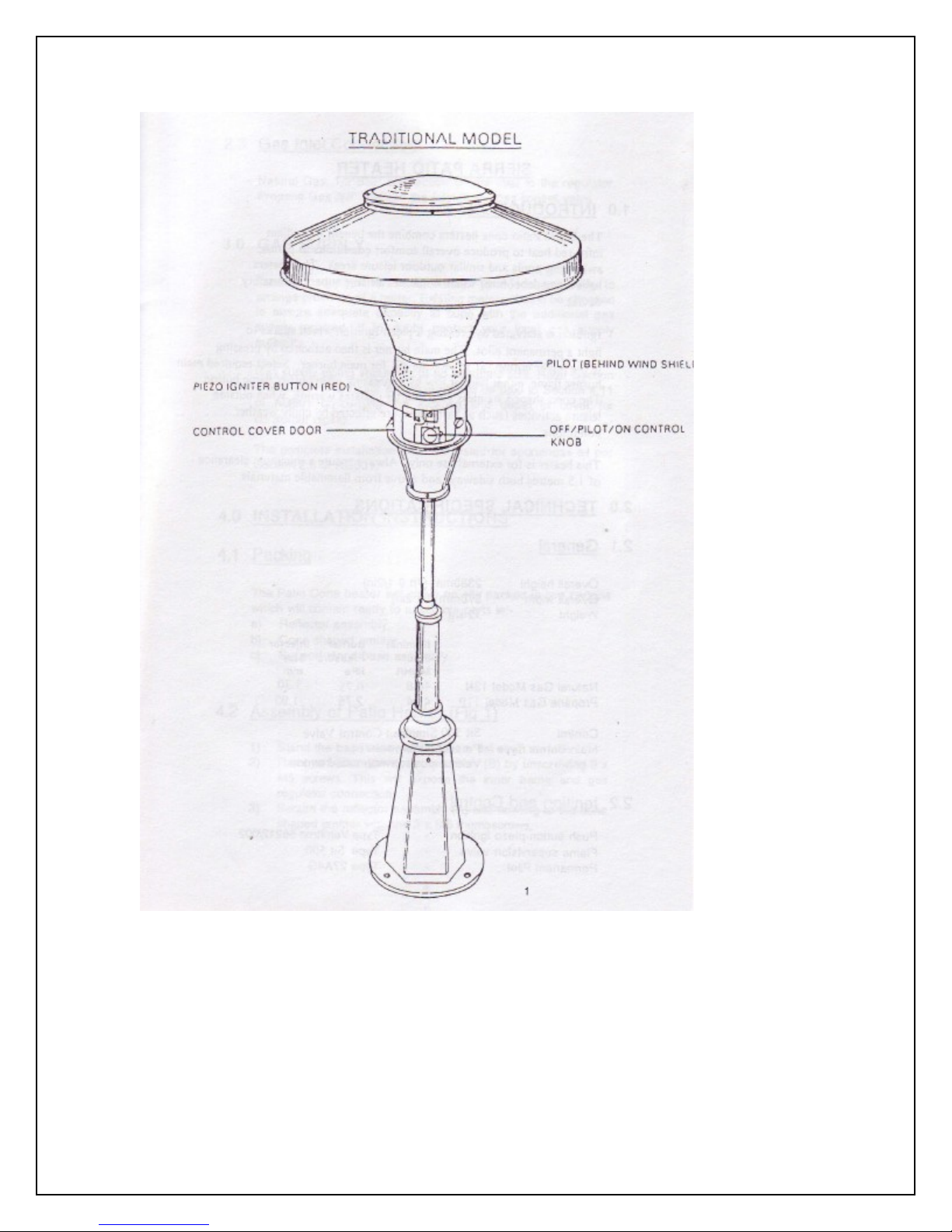
The Sierra Cone Patio Heaters combine the benefits of radiant heat to produce overall
comfort conditions to patios, swimming pools and similar outdoor leisure areas. The
heaters have a manual control which combines a flame supervision safety device.
Ignition is activated by pressing a piezo ignition which sparks to light a permanent pilot.
The main burner is then activated by pressing in the lower button to indicate for
main burner. Select required main burner flame, either high or low by depressing main
burner flame button. The cone shaped stainless steel emitter radiates warmth, when
outside leisure activities (such as barbeques) are effected by chilly weather conditions.
The heater is for external use only. Always ensure a minimum clearance of 1.5 meters
both sideways and 400mm above from flammable materials.
2.0 Technical Specifications
2.1 General
Overall Height 2380mm (7ft 9-1/2in)
Overall Width 970mm (3ft 2in)
Weight 32 kg
Natural Gas Model 13N 46.8 0.75 3.30
Propane Gas Model 11P 41.4 2.75 1.90
Nominal Input Burner Pressure Injector Size
MJ/HR kPa MM
Control Sit 500 Simplosit Control Valve
Main Burner Type Pressed steel venturi; vertical position with cast iron top.
2.2 Ignition and Control
Push button piezo ignition type Vernitron 66212/002
Flame supervision valve type Sit 500
Permanent pilot type 27A4G
2.3 Gas Inlet Connection
Natural Gas. ½” BSP connection on the inlet to the regulator.
Propane Gas. 3/8” BSP on the inlet to the gas control valve.
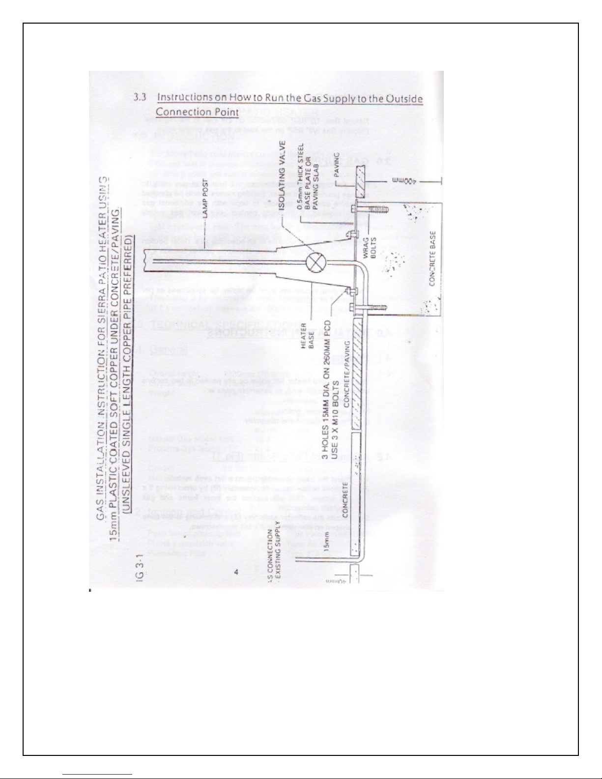
3.0 Gas Supply
If no gas supply is available, contact your local gas utility to arrange provision of a meter.
Existing meters should be checked to ensure adequate capacity to cope with the
additional gas supply required. If in doubt contact your local gas supply authority.

3.0 Gas Supply continued.
Gas supply piping should be of an adequate size. Refer section 4 of AG601. Particular
attention should be paid to section 4.11 of AG601 concerning the location and depth of
cover for consumer piping.
The complete installation must be tested for soundness as per section 2.6 of AG601.
4.0 Installation Instructions
4.1 Packing
The patio heater will arrive packed in two cartons which will contain ready to assemble
parts i.e.:a. Reflector
b. Cone shaped emitter
c. Support stand base assembly
4.2 Assembly of Patio Heater (Fig. 1)
1. Stand the base assembly (e) on a flat even surface.
2. Remove bottom cover on assembly (b) by unscrewing 3 x M5 screws. This will expose
the inner frame and gas regulator connection.
3. Secure the reflector assembly (a) and cowling to the cone shaped emitter with the 3 x
M8 thumbscrew.
 Loading...