

Page 1
HRX-OM-J049-A
1st edition: Aug. 2006
Rev. A: May. 2007
Operation Manual
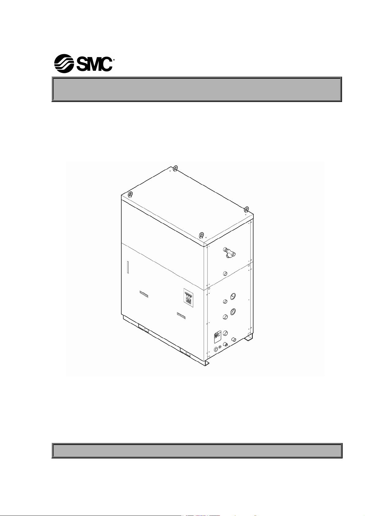
Water-refrigerated Thermo cooler
HRG010-W
HRG015-W
SMC Corporation
Save This Manual Carefully for Use at Any Time
© 2006 SMC CORPORATION All Rights Reserved
Page 2

To the Customers
Thank you for purchasing our THERMO COOLER HRG Series (hereinafter called “This unit”).
For safety and efficiency, be sure to read and understand this manual thoroughly before performing
operation of this unit.
z All warnings and precautions defined in this manual shall be observed.
z This manual provides instructions for the installation and operation of the unit. Only personnel who
understand basic operation described in this manual are qualified to perform the installation and
operation of the unit.
z Copying, duplicating or transferring any part of or whole contents of this manual without SMC
Corporation’s permission is strictly prohibited.
Note: The contents of this manual are subject to change without notice.
Page 3

HRX-OM-J049-A
Table of Contents
Table of Contents
Chapter 1 Safety Instructions........................................................... 1-1
1.1 Before Using this Unit............................................................................................. 1-1
1.2 Danger, Warning and Caution................................................................................. 1-2
1.2.1 Level of risk ......................................................................................................................... 1-2
1.2.2 Definitions of “Serious injury” and “Minor injury” ................................................................. 1-2
1.2.3 Symbols............................................................................................................................... 1-3
1.3 Hazard Warning Label............................................................................................. 1-4
1.3.1 Classification of risks........................................................................................................... 1-4
1.3.2 Type of hazard warning labels ............................................................................................ 1-5
1.3.3 Location of hazard warning label ........................................................................................ 1-6
1.4 Model label............................................................................................................... 1-6
1.5 Safety Measures...................................................................................................... 1-7
1.5.1 Safety Precautions ..............................................................................................................1-7
1.5.2 Protective equipment........................................................................................................... 1-8
1.6 Emergency Measures.............................................................................................. 1-9
1.7 Disposition of Waste ............................................................................................. 1-10
1.7.1 Recovery of refrigerant and compressor oil ...................................................................... 1-10
1.7.2 Circulating fluid disposal.....................................................................................................1-11
1.7.3 System disposal .................................................................................................................1-11
1.8 Material Safety Data Sheet (MSDS) .......................................................................1-11
Chapter 2 Appearance and Each Section ........................................ 2-1
2.1 Appearance.............................................................................................................. 2-1
2.2 Name of Each Section............................................................................................. 2-2
2.2.1 HRG010-W .......................................................................................................................... 2-2
2.2.2 HRG015-W .......................................................................................................................... 2-3
2.3 Control panel ........................................................................................................... 2-4
Chapter 3 Transport and Installation................................................ 3-1
3.1 Transport.................................................................................................................. 3-1
3.1.1 Transporting with forklift and unit lifting ............................................................................... 3-2
3.1.2 Transporting with caster ...................................................................................................... 3-3
3.2 Installation ............................................................................................................... 3-4
3.2.1 Installation conditions .......................................................................................................... 3-4
3.2.2 Installation location .............................................................................................................. 3-5
3.2.3 Installation location and maintenance work area ................................................................ 3-6
3.2.4 Installation ........................................................................................................................... 3-7
3.2.5 Electrical wiring ................................................................................................................... 3-9
3.2.6 Piping................................................................................................................................. 3-13
HRG010-W HRG015-W
1st edition : Aug. 2006
Rev. A: May. 2007
TOC-1
Page 4

HRX-OM-J049-A
Table of Contents
3.2.7 Supply of circulating fluid................................................................................................... 3-15
3.2.8 Reinstallation of unit ..........................................................................................................3-16
Chapter 4 Startup and Shutdown ..................................................... 4-1
4.1 Pre-check..................................................................................................................4-1
4.1.1 Installation condition ............................................................................................................4-1
4.1.2 Electric wiring.......................................................................................................................4-1
4.1.3 Facility water piping ............................................................................................................. 4-1
4.1.4 Piping for circulating fluid..................................................................................................... 4-1
4.1.5 Supply of circulating fluid.....................................................................................................4-1
4.2 Preparation for startup ............................................................................................ 4-2
4.2.1 Power supply .......................................................................................................................4-2
4.2.2 Setting of circulating fluid temperature ................................................................................4-2
4.2.3 Additional water supply........................................................................................................ 4-3
4.3 Unit Startup and Shutdown ..................................................................................... 4-4
4.3.1 Starting the unit....................................................................................................................4-4
4.3.2 Stopping the unit .................................................................................................................. 4-4
4.4 Check at startup.......................................................................................................4-5
Chapter 5 Error Message and Troubleshooting .............................. 5-1
5.1 Error Message..........................................................................................................5-1
5.2 Troubleshooting.......................................................................................................5-2
5.3 Alarm Reset (Alarm Lamp OFF) ..............................................................................5-3
5.4 Recovery from Power Failure (POWER Lamp ON) ................................................5-6
Chapter 6 Unit Maintenance ............................................................. 6-1
6.1 Control of Water Quality ..........................................................................................6-1
6.2 Inspection and Cleaning..........................................................................................6-2
6.2.1 Daily inspection....................................................................................................................6-3
6.2.2 Quarterly inspection............................................................................................................. 6-4
6.2.3 Biannual inspection.............................................................................................................. 6-4
6.2.4 Check during wintertime ...................................................................................................... 6-5
6.3 Consumables ...........................................................................................................6-6
6.4 Long-term Storage................................................................................................... 6-6
Chapter 7 Documents ....................................................................... 7-1
7.1 Standard Specifications ..........................................................................................7-1
7.2 Optional Specifications ........................................................................................... 7-3
7.3 Outline Dimensions .................................................................................................7-4
7.3.1 HRG010-W, HRG010-W-B, HRG010-W-C, HRG010-W-BC HRG015-W, HRG015-W-B,
HRG015-W-C, HRG015-W-BC............................................................................................ 7-4
7.3.2 HRG010-W-A□, HRG015-W-A□ ....................................................................................... 7-4
7.4 Electric Circuit..........................................................................................................7-5
7.4.1 HRG010-W, HRG015-W...................................................................................................... 7-5
HRG010-W HRG015-W
1st edition : Aug. 2006
TOC-2
Rev. A: May. 2007
Page 5

HRX-OM-J049-A
Table of Contents
7.4.2 HRG010-W-BC, HRG015-W-BC......................................................................................... 7-6
7.5 Flow Chart................................................................................................................ 7-7
7.6 Daily Inspection Sheet............................................................................................ 7-8
HRG010-W HRG015-W
1st edition : Aug. 2006
Rev. A: May. 2007
TOC-3
Page 6

HRX-OM-J049-A
Table of Contents
TOC-4
HRG010-W HRG015-W
1st edition : Aug. 2006
Rev. A: May. 2007
Page 7

Chapter 1 Safety Instructions
Chapter 1 Safety Instructions
Be sure to read and understand all the important precautions in this
manual before operating the unit.
1.1 Before Using this Unit
This chapter describes the safety-related items that users should be aware of upon
z
handling this unit.
This unit is an isothermal fluid circulation system housed in the tank. SMC’s
z
liability under this warranty shall not be available for troubles caused by use for
purposes other than the original intent.
This unit operates under high voltage and contains components that cause a rise
z
in temperature and rotate. All personnel are required to read and understand the
safety-related items in this manual before working with this unit.
HRX-OM-J049-A
This manual is not for comprehensive safety and hygiene education. Such a
z
manual should be provided by a safety training manager.
All personnel who work on or around this unit are to have proper training and
z
education on dangers specific to this unit and safety measures against potential
hazards.
A safety manager is responsible for observing safety standards. Operators and
z
service technicians have individual responsibilies for their safety during
operation of this unit in his/her daily work.
Operators must individually take account of safety and assure a proper working
z
area and working environment.
The relevant personnel must receive proper safety education before working on
z
this unit to prevent dangers. Never conduct work training without giving proper
consideration to safety.
Save this manual at a designated place for reference when necessary.
z
HRG010-W HRG015-W 1.1 Before Using this Unit
1st edition : Aug. 2006
Rev. A: May. 2007
1-1
Page 8
HRX-OM-J049-A
Chapter 1 Safety Instructions
1.2 Danger, Warning and Caution
1.2.1 Level of risk
This unit is designed with the safety of workers and the prevention of system
damage. This manual classifies the risks into the following three categories
according to the level of the hazard: Danger, Warning, and Caution. Read the
statements carefully and thoroughly understand them before operating this unit.
DANGER, WARNING and CAUTION signs are in order according to severity
(DANGER > WARNING > CAUTION). See below for the details.
"DANGER" denotes that there is an imminent hazard which will cause serious
personal injury or death during operation.
"WARNING" denotes that there is a hazard which may cause serious personal injury
or death during operation.
"CAUTION" denotes that there is a hazard which may cause minor personal injury
during operation.
"CAUTION" without an exclamation symbol denotes that there is a hazard which
may cause damage or failure of this unit, facility, or devices.
[Tips]
Tips are provided when there is information personnel are required to be
aware of for system operation and maintenance. If the task carries useful
information, the relevant tips are given as well.
1.2.2 Definitions of “Serious injury” and “Minor injury”
“Serious injury”
This term describes injuries such as loss of eyesight, wound, burns, frostbite, electric
shock, fracture, and toxication that leaves aftereffects which may require prolonged
treatment and hospitalization.
“Minor injury”
This term describes injuries that do not require prolonged treatment or
hospitalization (injuries other than “serious injuries” described above).
1.2 Danger, Warning and Caution HRG010-W HRG015-W
1-2
1st edition : Aug. 2006
Rev. A: May. 2007
Page 9
1.2.3 Symbols
This manual provides the following symbols in addition to “Danger”, “Warning”,
and “Caution” to present the warning details in easy-to-understand manner.
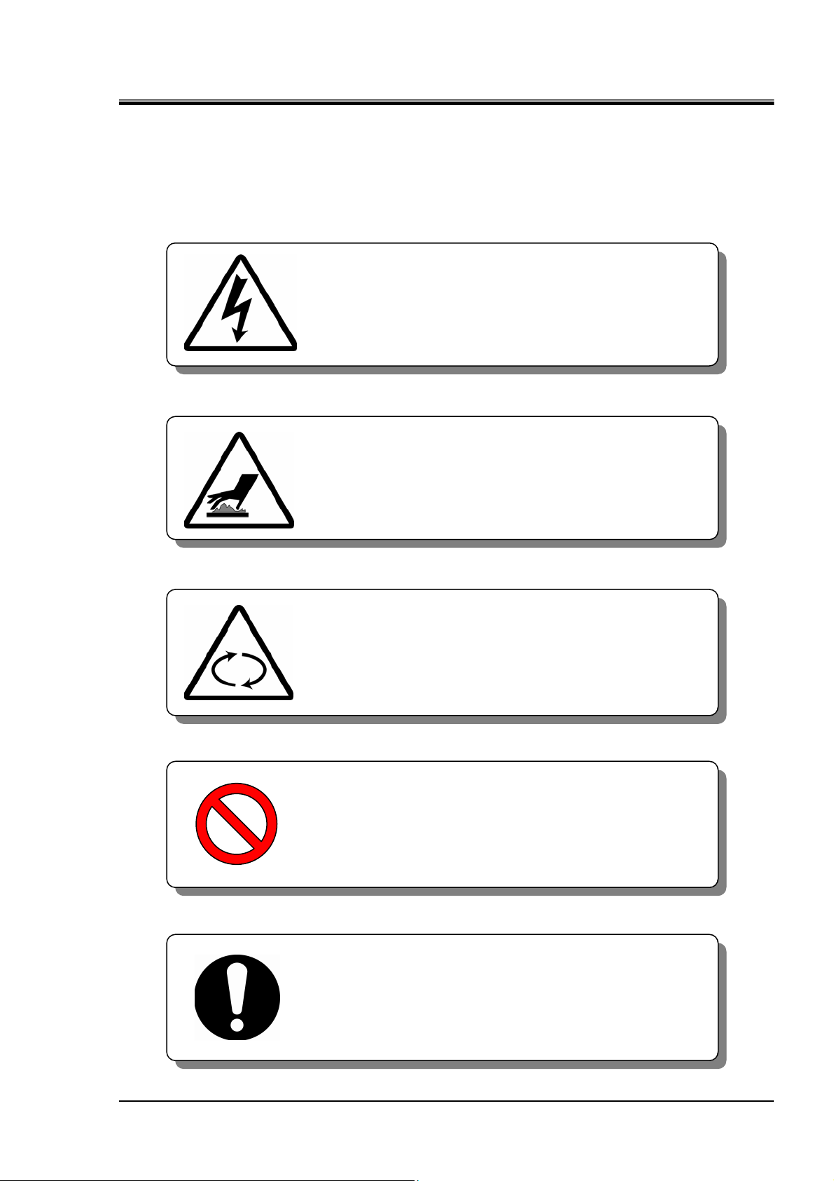
Symbol of electrical hazard
This symbol warns you of possible risk of electrical
shock.
Symbol of heat hazard
This symbol warns you of potential burns.
HRX-OM-J049-A
Chapter 1 Safety Instructions
Symbol of rotating shaft hazard
This symbol warns you of possible risk caused by a
rotating object.
Symbol of “Don’ts”
This symbol denotes the items that must not be
attempted.
Symbol of “Dos”
This symbol denotes the “obligation” items which
you must follow in operation of this unit.
HRG010-W HRG015-W 1.2 Danger, Warning and Caution
1st edition : Aug. 2006
Rev. A: May. 2007
1-3
Page 10
HRX-OM-J049-A
p
Chapter 1 Safety Instructions
1.3 Hazard Warning Label
The hazard warning labels indicate where potential hazards are present during unit operation
and maintenance.
The hazard warning labels are in appropriate sizes and colors. They contain symbols in
addition to the descriptions of warnings.
1.3.1 Classification of risks
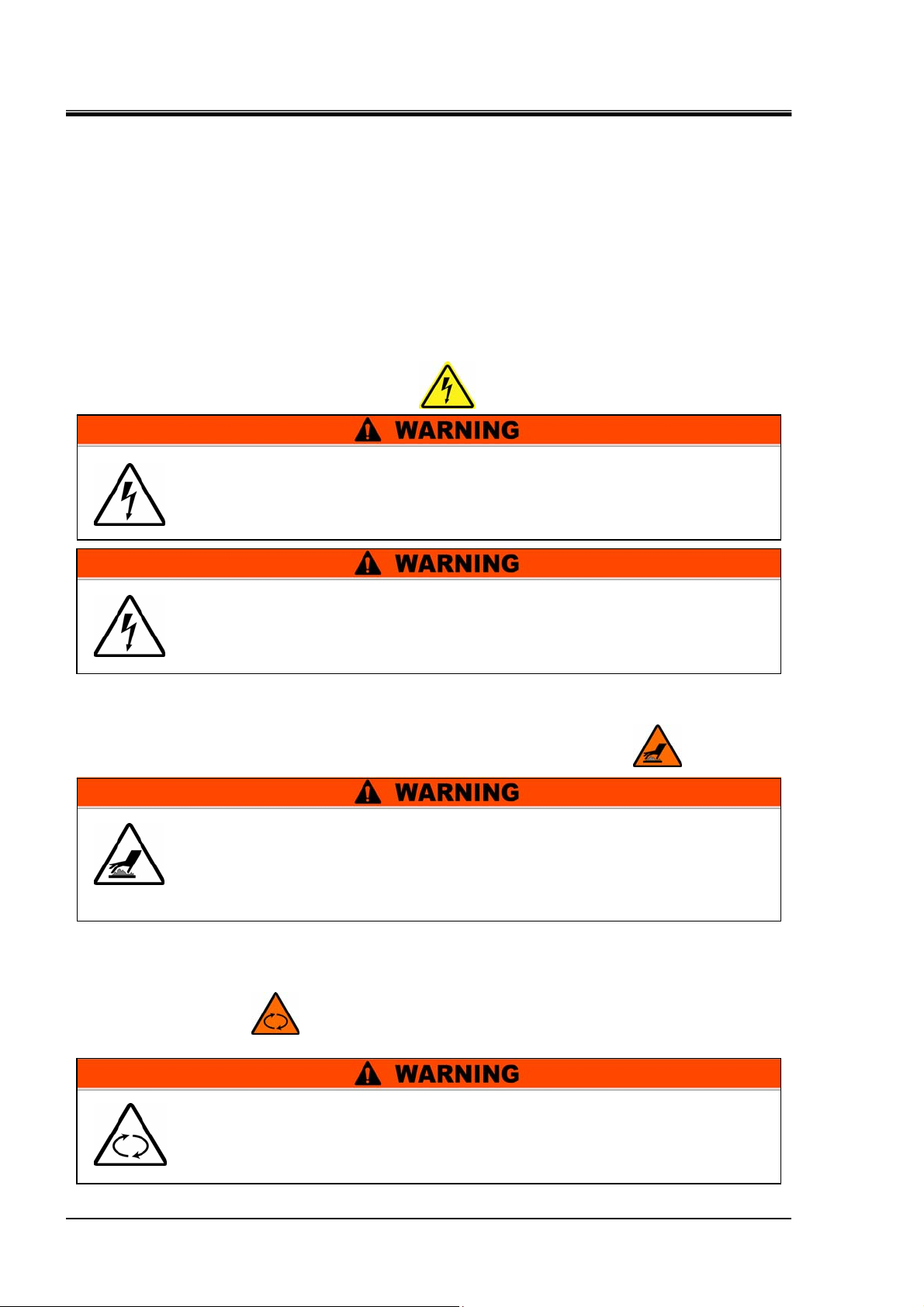
High voltage hazards
The unit is operated at high voltage and may cause an electrical shock. The
attached label contains the symbol
Only operate the unit with the cover panel attached.
The unit contains the power supply carrying high voltage inside that is
isolated with the cover panel.
Only trained personnel are allowed to work, including unit inspection,
around the power supply.
High temperature hazards
The unit reaches high temperature during operation and may cause burns when
an operator comes in contact. The attached label contains the symbol
There is the presence of the surface in the unit that is at high
temperatures during operation. Potential burns may occur if touched.
Residual heat may cause burns despite the power being turned OFF.
Be sure of the surface reaching room temperature before work.
.
.
Rotating object hazards
The unit includes several parts that rotate during operation and may cause the
operator to get the finger caught in these parts. The attached label contains the
symbol
The unit contains a section which rotates when it is in action. Potential
personal injury may occur if touched. A rotator is structured to come
to a temporary stop and resume rotation.
Avoid
1.3 Hazard Warning Label HRG010-W HRG015-W
1-4
.
erforming work during system operation.
1st edition : Aug. 2006
Rev. A: May. 2007
Page 11
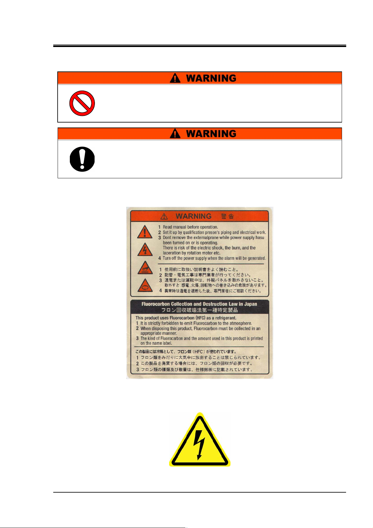
1.3.2 Type of hazard warning labels
Do not remove or deface the warning labels.
Read the contents of the hazard warning labels with care to keep them
in mind.
Warning label on the front panel
HRX-OM-J049-A
Chapter 1 Safety Instructions
Fig. 1-1 Warning Label on the Front Panel
Warning label for high voltage
Fig. 1-2 Warning Label for High Voltage
HRG010-W HRG015-W 1.3 Hazard Warning Label
1st edition : Aug. 2006
Rev. A: May. 2007
1-5
Page 12
HRX-OM-J049-A
Chapter 1 Safety Instructions
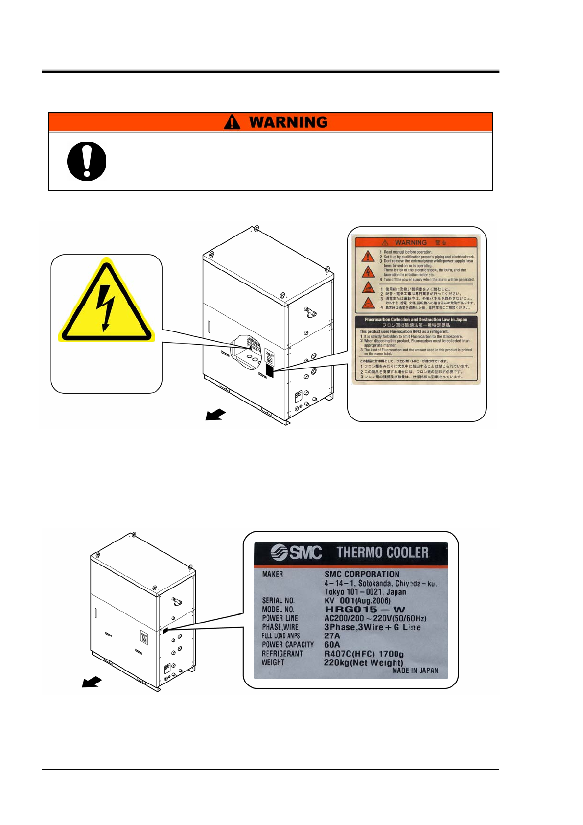
1.3.3 Location of hazard warning label
z Recognize where the hazard warning labels are attached.
z The user is not allowed to reposition the labels. If the label is
replaced due to being peeled off or worn out, keep the previous
position.
Warning label for
Left
high
1.4 Model label
Check the model no. described on the label.
Front
Fig. 1-3 Location of Hazard Warning Label
Warning label on the
front panel
Front
1.4 Model label HRG010-W HRG015-W
1-6
Fig. 1-4 Location of Model Label
1st edition : Aug. 2006
Rev. A: May. 2007
Page 13
1.5 Safety Measures
1.5.1 Safety Precautions
While this system is protected by various safety measures, the following basic safety
precautions should be observed to assure further safe operations.
Follow the following instructions upon operation of this system.
Failure to follow the instructions can lead to personal injury or
hazardous accidents.
Read and understand this manual thoroughly before operation of this system.
z
Before operating the system during maintenance, inform all personnel who are
z
working in the vicinity of the system to alert them of your action.
Use appropriate tools and follow proper procedures.
z
HRX-OM-J049-A
Chapter 1 Safety Instructions
See “1.5.2 Protective equipment”on page 1-8 to wear protective equipment
z
properly.
Refer to your safety manual for emergency evacuation.
z
Use assistance to carry object over 20 kg.
z
Check that all parts and screws are returned to the pre-work conditions at the end
z
of work.
Do not work when intoxicated or feeling ill. Accidents may occur if disregarded.
z
Do not remove a panel unless permitted in this manual.
z
HRG010-W HRG015-W 1.5 Safety Measures
1st edition : Aug. 2006
Rev. A: May. 2007
1-7
Page 14
HRX-OM-J049-A
Chapter 1 Safety Instructions
1.5.2 Protective equipment
This manual defines protective equipment according to work type.
Wear proper protective equipment as shown below, according to work type.
Read and understand the relevant operation manual thoroughly prior
to use of protective equipment.
For system transportation, installation and removal
For handling circulating fluid
For system operation
z Protective footwear z Protective gloves z Hard hat
z Protective footwear z Protective gloves z Protective mask
z Protective apron z Protective goggles
z Protective footwear z Protective gloves
1.5 Safety Measures HRG010-W HRG015-W
1-8
1st edition : Aug. 2006
Rev. A: May. 2007
Page 15
HRX-OM-J049-A
Chapter 1 Safety Instructions
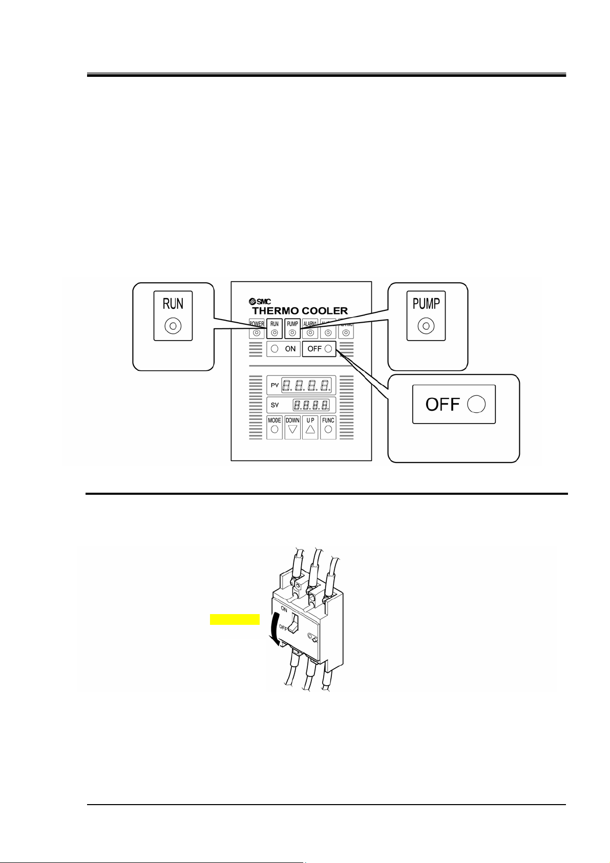
1.6 Emergency Measures
Press the [OFF] switch on the control panel located on the front of the thermo cooler
only if the need to shut off the power arises due to emergency such as natural
disaster, fire, earthquake or personal injury.
With the press of the [OFF] switch, the thermo cooler comes to a stop. The power
supply, however, is designed not to stop, which enables the motor circuit to remain
partially energized.
Make sure to turn off the main power supply (main breaker) before proceeding with
the next task.
1. Press the [OFF] switch on the control panel to bring the thermo cooler to a stop.
[RUN] LED [PUMP] LED
[OFF] LED
Fig. 1-5 Thermo Cooler OFF
2. Always turn off the main breaker (for your power supply equipment).
Switch it off.
前面
Fig. 1-6 Main Power Shutdown (Breaker OFF)
HRG010-W HRG015-W 1.6 Emergency Measures
1st edition : Aug. 2006
Rev. A: May. 2007
1-9
Page 16
HRX-OM-J049-A
Chapter 1 Safety Instructions
1.7 Disposition of Waste
1.7.1 Recovery of refrigerant and compressor oil
The unit belongs to Class 1 in the “Fluorocarbon Recovery and Destruction Law”
and uses freon type refrigerant (HFC) and compressor oil. When these fluids need to
be recovered, read the instructions below and ensure thorough understanding of
them. If you have any questions, contact the local distributor.
Only service personnel or qualified personnel are allowed to open the
panel of the unit.
Do not mix the compressor oil with domestic waste for disposition.
Also, incineration is permitted only at an authorized incinerator.
Comply with municipal ordinances or regulations to dispose of waste.
The release of refrigerant to atmosphere is banned by law. If the
refrigerant needs to be removed, recover it with specific equipment
and request a specialized waste disposal agency for disposal of the
recovered refrigerant. A person must have proper license to perform
refrigerant recovery.
Only personnel with sufficient knowledge and experiences with the
unit and associated equipment are allowed to recover refrigerant and
compressor oil. The person must have proper license to perform
refrigerant recovery.
[Tips]
The type and amount of used freon can be found on the label.
1.7 Disposition of Waste HRG010-W HRG015-W
1-10
1st edition : Aug. 2006
Rev. A: May. 2007
Page 17

1.7.2 Circulating fluid disposal
As to the disposal of a circulating fluid (ethylene glycol solution), consign the
specialized industrial waste disposal agency with the contents detailed.
1.7.3 System disposal
As to the disposal of this system, consign the specialized industrial waste disposal
agency in accordance with law on Waste Disposal and Cleaning.
1.8 Material Safety Data Sheet (MSDS)
Material Safety Data Sheet (MSDS) is supplied separately. Contact the system
supplier if you need the MSDS regarding chemicals used in this system.
For each chemical you purchased, the relevant MSDS is to be obtained under your
responsibility. Keep the MSDS along with this manual in the condition that allows
all personnel to check the contents anytime to gain the understanding of potential
hazards.
HRX-OM-J049-A
Chapter 1 Safety Instructions
HRG010-W HRG015-W 1.8 Material Safety Data Sheet (MSDS)
1st edition : Aug. 2006
Rev. A: May. 2007
1-11
Page 18

HRX-OM-J049-A
Chapter 1 Safety Instructions
1.8 Material Safety Data Sheet (MSDS) HRG010-W HRG015-W
1-12
1st edition : Aug. 2006
Rev. A: May. 2007
Page 19
HRX-OM-J049-A
Chapter 2 Appearance and Each Section
Chapter 2 Appearance and Each Section
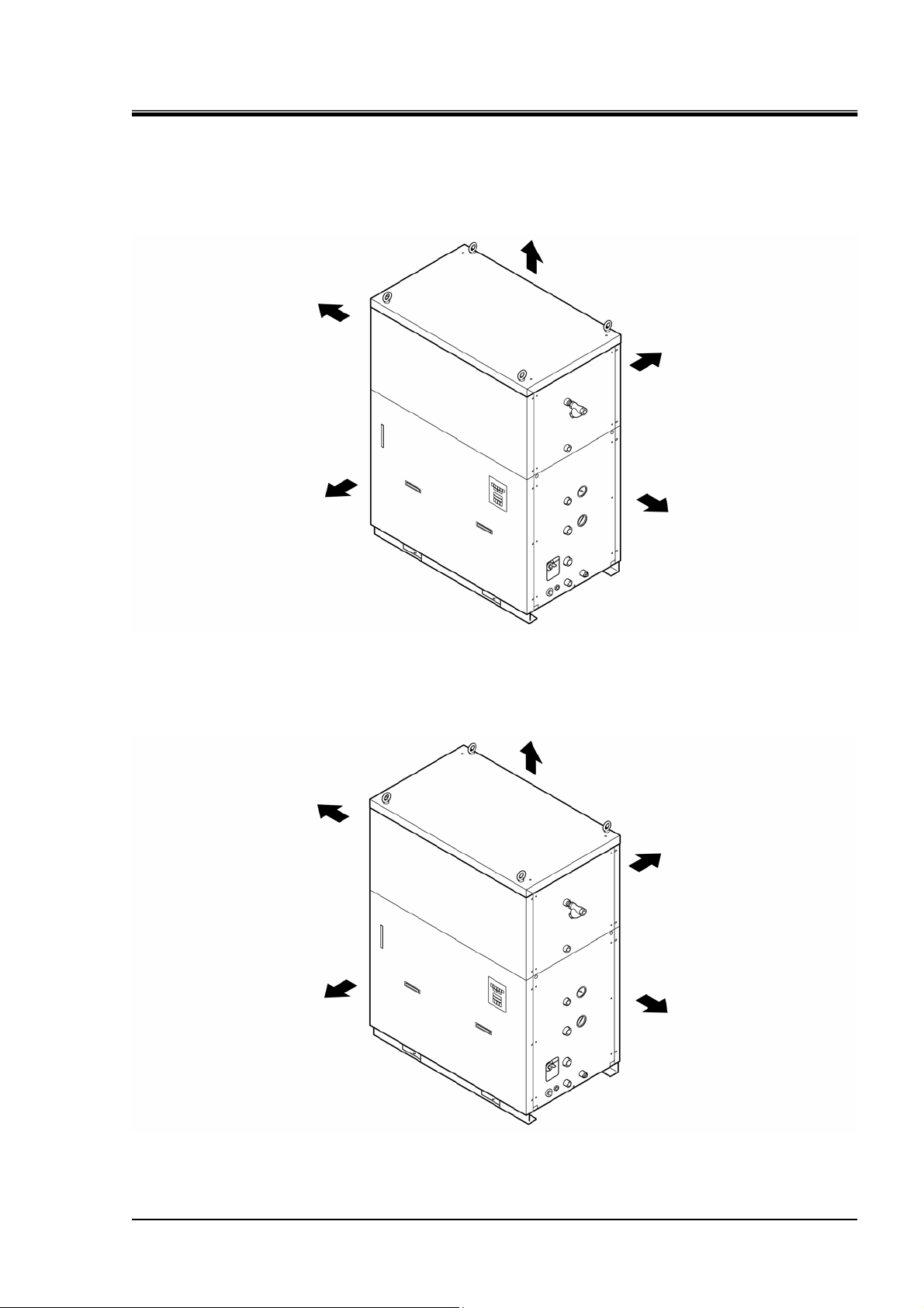
2.1 Appearance
Left
Front
Top
Back
Right
Left
Front
Fig. 2-1 Appearance of HRG010-W
Top
Back
Right
Fig. 2-2 Appearance of HRG015-W
HRG010-W HRG015-W 2.1 Appearance
1st edition : Aug. 2006
Rev. A: May. 2007
2-1
Page 20
HRX-OM-J049-A
Chapter 2 Appearance and Each Section
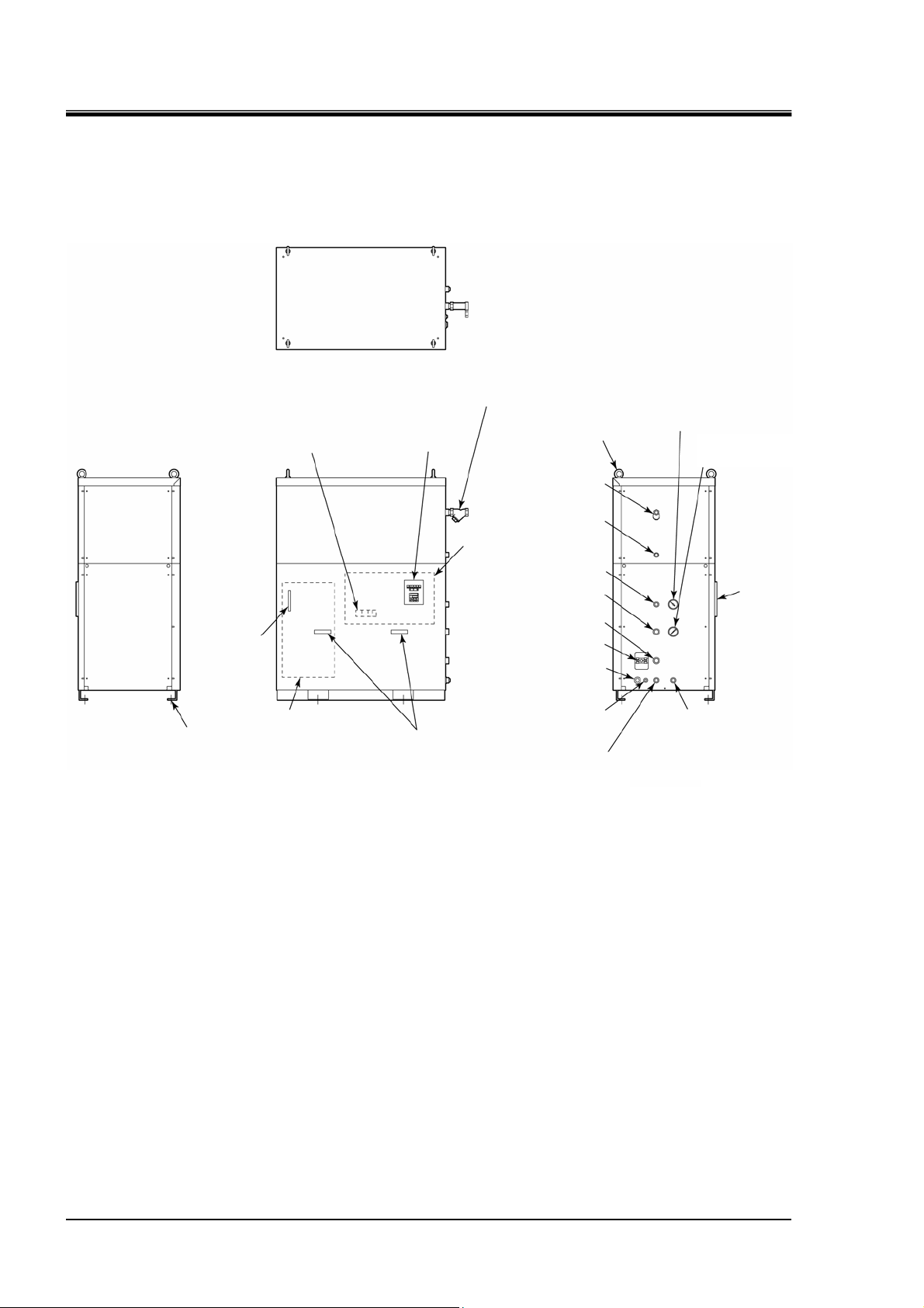
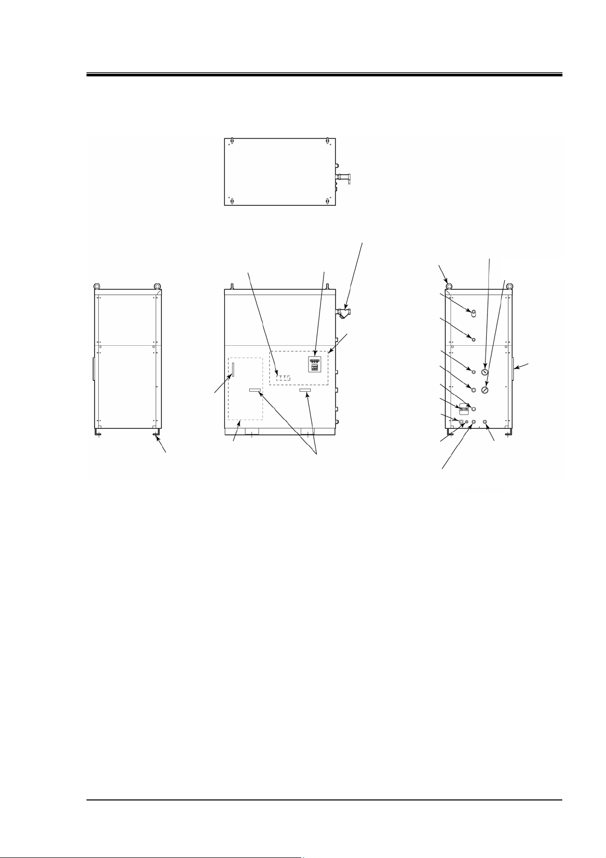
2.2 Name of Each Section
2.2.1 HRG010-W
Left
Level gauge
4-Ø13
(For anchor bolt)
Top
Power/signal connection
terminal block
Tank
Front
Control panel
Circulating fluid OUT Rc3/4
Handle
Y-shaped strainer Rc1/2
(accessory)
Eyebolt M12
Facility water IN Rc1/2
Facility water OUT Rc1/2
Electrical unit
Auto supply port Rc1/2
Circulating fluid RETURN
Rc3/4
Manual relief valve
Power cable access
(Cable Grip)
Signal cable access
(Cable Grip)
Tank drain port Rc1/2
(plugged)
Refrigerant high
pressure gauge
Circulating fluid
pressure gauge
Ventilating hole
Port for overflow Rc1/2
Right
Fig. 2-3 Name of Each Section (HRG010-W)
2.2 Name of Each Section HRG010-W HRG015-W
2-2
1st edition : Aug. 2006
Rev. A: May. 2007
Page 21
2.2.2 HRG015-W
HRX-OM-J049-A
Chapter 2 Appearance and Each Section
Left
Level gauge
4-Ø13
(For anchor bolt)
Top
Power/signal connection
terminal block
Tank
Front
Y-shaped strainer Rc1/2 (accessory)
Control panel
Facility water IN Rc1/2
Facility water OUT Rc1/2
Electrical unit
Auto supply port Rc1/2
Circulating fluid OUT Rc3/4
Circulating fluid RETURN
Manual relief valve
Power cable access
Signal cable access
Handle
Tank drain port Rc1/2
(plugged)
Eyebolt M12
(Cable Grip)
(Cable Grip)
Refrigerant high
pressure gauge
Circulating fluid
pressure gauge
Ventilating
hole
Rc3/4
Port for overflow Rc1/2
Right
Fig. 2-4 Name of Each Section (HRG015-W)
HRG010-W HRG015-W 2.2 Name of Each Section
1st edition : Aug. 2006
Rev. A: May. 2007
2-3
Page 22

HRX-OM-J049-A
Chapter 2 Appearance and Each Section
2.3 Control panel
The control panel on the system front allows you to perform basic system operation
including temperature adjsutment, system start and stop.
Fig. 2-5 Control Panel
Table 2-1 Control Panel
No. Name Function
1 Digital display, PV / SV
PV Indicates actual temperature of a circulating fluid
SV Indicates set temperature of a circulating fluid
2 [POWER] LED Lights up when the power is supplied.
3 [RUN] LED
4 [PUMP] LED
Lights up when the [ON] switch is pressed.
5 [ALARM 1] LED Lights up when an alarm 1 arises.
6 [ALARM 2] LED Lights up when an alarm 2 arises.
7 [ALARM 3] LED Lights up when an alarm 3 arises.
8 [ON] switch This is used to run the unit.
9 [OFF] switch This is used to stop the unit.
10 [MODE] key This is used to switch the screens between PV and SV.
11 [DOWN] key This is used to decrease set temperature.
12 [UP] key This is used to increase set temperature.
* See “Chapter 5 Error Message and Troubleshooting” for alarms 1 to 3.
2.3 Control panel HRG010-W HRG015-W
2-4
1st edition : Aug. 2006
Rev. A: May. 2007
Page 23

HRX-OM-J049-A
Chapter 3 Transport and Installation
Chapter 3 Transport and Installation
The unit must be handled in correct manner.
Exercise caution to asure personnel safety during the installation,
operation, maintenance, and inspection of the unit.
Only personnel with sufficient knowledge and experiences with the
unit and unit are allowed to transport, install and conduct maintenance
possibly exposed to dangerous situations.
3.1 Transport
The unit is heavy and poses potential danger at transportation. To prevent damage
to the unit, be sure to follow the instructions below when transporting the unit.
If the forklift is used for transporting, ensure that the fork is inserted in
a place as specified in Fig. 3-1 “Forklift Insertion Position and Unit
Lifting”.
z If eyebolts are used for lifting, ensure the unit is held at four points.
z Keep each eyebolt at an angle from Min. 60 degrees with repect to
the postion of the center of gravity when lifting the unit.
Never set the unit on its side.
The refrigerant oil will drain into refrigerant piping from the
compressor, reducing its amount in the compressor. It results in a
compressor failure.
Drain the residual fluid from piping as much as possible to prevent
spill.
If the forklift is used for transporting the unit, be sure to prevent the
fork from contacting the cover panel or pipe connection ports.
HRG010-W HRG015-W 3.1 Transport
1st edition : Aug. 2006
Rev. A: May. 2007
3-1
Page 24

HRX-OM-J049-A
Chapter 3 Transport and Installation
3.1.1 Transporting with forklift and unit lifting
Min. 60°
Forklift insertion side
Lifting position
Min. 60°
Forklift insertion side
Front
Fig. 3-2 Forklift Insertion Position and Unit Lifting
3.1 Transport HRG010-W HRG015-W
3-2
1st edition : Aug. 2006
Rev. A: May. 2007
Page 25

Chapter 3 Transport and Installation
3.1.2 Transporting with caster
HRG010-W-A / HRG015-W-A (caster-mounted option)
HRX-OM-J049-A
This unit is heavy, which requires assistance for this work. Exercise
caution and look out for sloped surfaces including ramps.
Do not grab piping or panel handles when transporting the sytem with
the casters.
Potential damage to piping and panels may occur if disregarded.
1. Push the corners of this unit with the adjusters uplifted.
The unit becomes disengaged so that it can be transported with casters.
Turn 360°.
Uplift the adjuster.
Turn 360°.
Caster w/ adjuster
Front
Handle
Pipe port
Fig. 3-3 Caster-mounted Option
HRG010-W HRG015-W 3.1 Transport
1st edition : Aug. 2006
Rev. A: May. 2007
3-3
Page 26

HRX-OM-J049-A
,
Chapter 3 Transport and Installation
3.2 Installation
Do not install the unit in a place possibly exposed to flammable gas.
Ignition may occur if leaked gas is collected around the unit.
This unit is NOT designed for outside use. The unit exposed to
moisture may develop a short circuit which can result in an electrical
shock
Install the unit on a flat and level floor which can support the weight of
the unit. Take measure to prevent the unit from tipping over. Improper
setup may cause water leakage from the unit and personal injury.
Keep ambient temperature of the unit between 5 and 40°C. Unit
operation at below 5°C may lead to failure in the compressor.
Operation at above 40°C will reduce effectiveness of the condenser
and trigger the safety device which brings the unit to a stop.
fire and failure in the unit.
3.2.1 Installation conditions
Do not use or store the unit in the following environments. Potential unit malfunction and
damage may occur if disregarded.
Environment that is exposed to water vapor, salt water or oil mist
z
Environment that is exposed to dust or powdery materials
z
Environment that is exposed to corrosive gas, flammable gas or solvent
z
Environment that is exposed to direct sun light or radiant heat
z
Environment where ambient temperature is out of the specified range between 5°C to 40°C
z
Environment that is subjected to abrupt changes in temprature
z
Environment that is subjected to strong electromagnetic noise (incl. strong electrical field,
z
strong magnetic field, or surge voltage)
Environment that generates static electricity, or condition in which static electricity
z
discharges to the unit
Environment that generates strong high frequencies
z
Environment at high altitudes of over 1000m
z
Condition which allows strong vibrations and impacts to transmit to the unit
z
Condition with external force or load to deform the unit
z
Condition with an insufficient maintenance space as required
z
Condition with no adequate space for ventilation
z
3.2 Installation HRG010-W HRG015-W
3-4
1st edition : Aug. 2006
Rev. A: May. 2007
Page 27

3.2.2 Installation location
Required water sources
Table 3-1 Heat Discharge and Required Quantity of Facility Water (HRG010-W, HRG015-W)
Model
HRG010-W Approx. 16 34
HRG015-W Approx. 23
Outside installation
A water-refrigerated thermo cooler is designed to exhaust heat
through a supply of facility water.
Secure water sources listed below.
Heat discharge
(kW)
HRG010 and HRG015 are IPx3-compliant rainproof systems but not rendered complete
waterproof. Install the system out of direct sunlight as well as direct rain and snow (e.g. under
the eaves).
Chapter 3 Transport and Installation
Facility water temp. range (°C)
5 to 32
(Rated temp.: 25)
HRX-OM-J049-A
Required water
quantity (L/min)
40
HRG010-W HRG015-W 3.2 Installation
1st edition : Aug. 2006
Rev. A: May. 2007
3-5
Page 28

HRX-OM-J049-A
Chapter 3 Transport and Installation
3.2.3 Installation location and maintenance work area
Installation with maintenance space is recommended. (See Fig. 3-4)
Ensure an adequate ventilation space for the temperature controller.
Failure to create sufficient space may lead to improper cooling and/or
controller stop.
Access maintenance work area should be required for maintenance.
Min. 800mm
60mm
Min. 800mm
Top
Min. 800mm
Front
Fig. 3-4 Recommended Installation Location
3.2 Installation HRG010-W HRG015-W
3-6
1st edition : Aug. 2006
Rev. A: May. 2007
Page 29

HRX-OM-J049-A
Chapter 3 Transport and Installation
3.2.4 Installation
Preparation of anchor bolts suitable for floor material is your
responsibility.
Prepare M12-anchor bolts (4 pcs.) for installation. See “ 7.3 Outline
Dimensions” for mounting of the anchor bolts.
Keep the unit away from vibration. Install the unit on a flat and stable surface.
z
Refer to “7.3 Outline Dimensions” for the dimensions of the unit.
z
Procedure for Installation
1. The anchor bolts (foundation bolts) are mounted on the level concrete foundation.
Lower this unit, inserting the anchor bolts into the unit.
2. Tighten the hexagonal nut to secure the unit onto the foundation.
3. Make sure of no looseness between the anchor bolts and foundation.
Anchor bolt mounting hole (Ø13)
Base
Hexagonal nut
Anchor bolt
Front
Concrete foundation
Fig. 3-5 Procedure for Installation
HRG010-W HRG015-W 3.2 Installation
1st edition : Aug. 2006
Rev. A: May. 2007
3-7
Page 30

HRX-OM-J049-A
Chapter 3 Transport and Installation
HRG010-W-A / HRG015-W-A (caster-mounted option)
As to the HRG010-W-A or HRG015-W-A (caster-mounted option), the
adjusters should be lowered to secure the system after installation.
Caster w/ adjuster Lower the adjusters to secure the system.
Fig. 3-6 HRG010-W-A / HRG015-W-A (Caster-mounted Option)
3.2 Installation HRG010-W HRG015-W
3-8
1st edition : Aug. 2006
Rev. A: May. 2007
Page 31

3.2.5 Electrical wiring
HRX-OM-J049-A
Chapter 3 Transport and Installation
z Do not modify the electrical wiring. Incorrect wiring can cause an
electrical shock and fire. Failure to do so will void any warranty.
z The set value of the safety device must not be changed. Changing
the set value can cause unit failure and fire.
z Only qualified personnel are allowed to install wiring.
z Be sure to disconnect the power for safety. Wiring installation with
the unit energized is strictly prohibitted.
z Use the specified cables. Properly apply strain relief to prevent an
external force from being exerted on the terminals. Poor or loose
connection can cause electrical shock, heat spots, or fire.
z Supply the power to the unit from a reliable power source (without
surge or sag voltage).
z Be sure to use a GFCI breaker to prevent an electrical shock and
burnt compressor motor. The breaker with adequate capacity of
current leakage and load should be selected in accordance with “7.1
Standard Specifications”.
z Ensure that the power supply meets the specification of the unit.
z Always establish a ground for safety.
z Do not connect the ground to a water line, gas pipe or lighting
conductor.
z Do not branch off the wiring to make multiple circuits. Potential hot
spots or fire may occur if disregarded.
Power supply cable and GFCI breaker
Select a cable for power supply and GFCI breaker corresponding to the model no.
provided in the following table.
Table 3-2 Cable for Power Supply and Current Leakage
Item HRG010-W HRG015-W
Power cable
Signal cable
Capacity of GFCI breaker
* Use the breaker with current sensitivity of 30mA at minimum.
Round crimp contact size 8 - 4S 14 - 5S
Y-shaped crimp contact size 1.25Y - 3
Size 4- core 8 mm2 4- core 14 mm2
Size 6- core 0.75 mm2
*
40A 60A
HRG010-W HRG015-W 3.2 Installation
1st edition : Aug. 2006
Rev. A: May. 2007
3-9
Page 32

HRX-OM-J049-A
Chapter 3 Transport and Installation
How to conduct wiring
1. Undo the screws (6 pcs.) and take off the front panel.
Screw
Front panel
Front
Fig. 3-7 Removal of Front Panel
Electrical unit
Screw
2. Connect the power supply cable and signal cable as shown in the figure.
Front
Fig. 3-8 Electrical Wiring
Signal cable access
Power cable access
Signal cable Power cable
3.2 Installation HRG010-W HRG015-W
3-10
1st edition : Aug. 2006
Rev. A: May. 2007
Page 33

Electrical wiring diagram
HRX-OM-J049-A
Chapter 3 Transport and Installation
z Prepare cables for the power supplyand signal lines separately .
z Maintain polarities (+, -) of DC24V when connecting the signal cable for
transmitting start/stop command (remote operation).
z Refer to “7.4 Electric Circuit” for the electrical circuit of the unit.
• HRG010-W
ELB/Current leakage breaker
Power supply input
z
User’s preparation
Power supply
cable
Electrical unit
Remote operation signal input
(Remote start upon input of DC+24V)
Remote stop upon input of DC 0V)
Error deteced stop signal output, relay contact
(normally open, closed for error
Contact closed during power-off)
Operation signal output, relay contact
(normally close, opened for error
Contact open during power-off)
Signal cable
FG (Frame ground)
Electrical circuit
Remote operation input circuit
Error detected stop
signal output circuit
Operation signal output circuit
I/O board
Fig. 3-9 Electrical Wiring Diagram (HRG010-W)
• HRG015-W
ELB/Current leakage breaker
Power supply input
Remote operation signal input
(Remote start upon input of DC+24V)
Remote stop upon input of DC 0V)
Error detected stop signal output, relay contact
(normally open, closed for error
Contact closed during Power-off)
Operation signal output, relay contact
(normally close, opened for error
Contact open during power-off)
Fig. 3-10 Electrical Wiring Diagram (HRG015-W)
User’s preparation
Power supply
cable
Signal cable
Electrical unit
Electrical circuit
FG (Frame ground)
Remote operation input circuit
Remote operation input circuit
Operation signal output circuit
I/O board
HRG010-W HRG015-W 3.2 Installation
1st edition : Aug. 2006
Rev. A: May. 2007
3-11
Page 34

HRX-OM-J049-A
Chapter 3 Transport and Installation
Procedures for communication cable wiring installation (RS485)
HRG010-W-C / HRG015-W-C (communication feature-laden option)
The communication cables are to adhere to specifications shown below.
Table 3-3 Communication Cable
Item Specifications
Communication cable
Y-shaped crimp contact size 1.25Y-3
Size Shielded twisted-pair wire (0.75mm2)
1. Connect the power cables properly, as shown below.
Front
Fig. 3-11 Communication Cable Wiring
Signal cable access
(communication cable access)
Communication cable
2. Have the converters listed below available. Establish connection with the computer (with a
RS232C terminal).
Table 3-4 Converter (Example)
Item Specifications
RS232C ⇔ RS485 converter
Part number: KS-485
Manufacturer: System Sacom
Connecting connector D-sub 9-pin (male)
Computer ⇔ Converter coupling cable
3.2 Installation HRG010-W HRG015-W
3-12
Part number:AR-305
Manufacturer: Arvel
1st edition : Aug. 2006
Rev. A: May. 2007
Page 35

3.2.6 Piping
HRX-OM-J049-A
Chapter 3 Transport and Installation
Only expert engineers or personnel who have adequate knowledge of
and experiences with piping installation are allowed to install piping.
Potential fluid leakage or stagnant fluid may occur if disregarded.
z Install piping properly. Failure to conduct proper piping installation
z Keep facility water pressure below 0.5MPa.
z Make sure the locations of IN and OUT ports for circulating fluid
z Make sure no entry of dust and foreign materials into the water
z Hold the piping connected port with a pipe wrench when tightening
z Hold the piping connected port with a pipe wrench when tightening
Pipe diameter
Facility water IN Rc1/2 Rc3/4
Facility water OUT Rc1/2 Rc3/4
Auto supply port Rc1/2
Circulating fluid OUT Rc3/4
Circulating fluid RETURN Rc3/4
Port for overflow
Port for drain in tank Rc1/2
may result in the entry of supplied and drained water into the inside
of the building, which may cause the work area and equipment to
get wet.
supply. The reverse connection inhibits proper operation of the unit.
circuit during piping installation.
the pipe. Excessive force will damage the port and cause leaks if
disregarded.
piping.
Pipe
Table 3-5 Pipe diameter
Diameter
HRG010-W HRG015-W
Rc1/2
Recommended
tightening torque
28 to 30N·• m
28 to 30N·• m
28 to 30N·• m
28 to 30N·• m
28 to 30N·• m
28 to 30N·• m
28 to 30N·• m
How to install piping
1. Hold the piping connected port with a specific wrench and tighten the pipe.
[Tips]
Install a valve at the drain port to facilitate the replacing and draining of the circulating fluid from the
tank described in chapter 6 “Unit Maintenance”. (The valve needs to be prepared separately.)
HRG010-W HRG015-W 3.2 Installation
1st edition : Aug. 2006
Rev. A: May. 2007
Fig. 3-12 Tightening of Pipe
Pipe coupling hole
Sealant
3-13
Page 36

HRX-OM-J049-A
Chapter 3 Transport and Installation
Recommended piping installation
Facility water IN
Facility water OUT
Auto supply port Fluid supply
Facility water
Circulating fluid OUT
Circulating fluid RETURN
Port for overflow
Tank drain port
No. Name
Load device
To the drain port
Fig. 3-13 Recommended Piping Installation
Table 3-6 Recommended Piping Installation
Size
HRG010-W HRG015-W
1 Valve Rc1/2 Rc3/4
2 Y-shaped strainer Rc1/2 Rc3/4
3 Pressure gauge 0 to 1.0 MPa
4 Valve Rc3/4
5 Relieving valve Rc3/4, set from 0 to 0.5 MPa
6 Y-shaped strainer Rc3/4
7 Flow meter Rc3/4, 0 to 100 L/min
[Tips]
Optional accessories listed below are available for the relieving valves shown
in Fig. 3-12 “Recommended Piping Installation”. Separate order for optional
accessories is to be placed upon designing the piping system if used for
piping installation.
Table 3-7 Allied Products
Part No. Name Qty. Note
HRG-BP010 Bypass (relieving valve) piping set 1 set HRG010 optional accessory
HRG-BP015 Bypass (relieving valve) piping set 1 set HRG015 optional accessory
3.2 Installation HRG010-W HRG015-W
3-14
1st edition : Aug. 2006
Rev. A: May. 2007
Page 37

Chapter 3 Transport and Installation
3.2.7 Supply of circulating fluid
1. Open the supply valve laid with pipes.
The fluid supply takes place with the use of the ball tap housed in the tank and stops automatically.
Keep the fluid level in the tank between “HIGH” and “LOW”.
If the circulating fluid is out of the range, the fluid may overflow.
Ensure piping is installed to the overflow outlet and drain pit.
Indicating range
Level gauge
HRX-OM-J049-A
Fig. 3-14 Level Gauge
HRG010-W HRG015-W 3.2 Installation
1st edition : Aug. 2006
Rev. A: May. 2007
3-15
Page 38

HRX-OM-J049-A
Chapter 3 Transport and Installation
3.2.8 Reinstallation of unit
If the unit is relocated, only personnel with knowledge of the unit and
associated equipment are allowed to perform unit reinstallation.
Precautions described below must always be followed.
Disconnection of power supply cable
When the unit is transferred to and reinstalled in a different place after operation at
the original place (including trial run), perform transporting and installation of the
unit according to the procedures described below and in Chapter 3.
Be sure to cut off the power supply when disconnecting the power supply cable.
z Only qualified personnel are allowed to install wiring.
z Be sure to cut off the power supply for safety. Wiring with the unit
energized is strictly prohibitted.
3.2 Installation HRG010-W HRG015-W
3-16
1st edition : Aug. 2006
Rev. A: May. 2007
Page 39

Chapter 4 Startup and Shutdown
Chapter 4 Startup and Shutdown
HRX-OM-J049-A
Personnel with adequate knowledge and experiences of this product
and peripheral devices shall be in charge of starting up and shutting
down the unit.
4.1 Pre-check
Check the following items before starting up the unit.
4.1.1 Installation condition
Make sure the unit is installed horizontally.
z
Do not put any heavy object on the unit or apply excess force by piping.
z
4.1.2 Electric wiring
Check that the power cable, ground and I/O signal cables are correctly connected.
4.1.3 Facility water piping
Check the I/O piping of the facility water is installed correctly.
4.1.4 Piping for circulating fluid
Check the I/O piping of the circulating fluid is installed correctly.
4.1.5 Supply of circulating fluid
Check the fluid level is within the specified range shown on the level indicator.
HRG010-W HRG015-W 4.1 Pre-check
1st edition : Aug. 2006
Rev. A: May. 2007
4-1
Page 40

HRX-OM-J049-A
Chapter 4 Startup and Shutdown
4.2 Preparation for startup
4.2.1 Power supply
1. Supply the power.
The following conditions are observed on the control panel upon power-ON.
After 4-sec display of the initial screen on the digital displays PV and SV, temperature and set temperature
z
of the circulating fluid will be displayed..
The [POWER] lamp comes on in 6 sec.
z
[POWER]LED
Digital display PV (circulating fluid temp.)
Fig. 4-1 Power Supply
Digital display SV (set temp.)
4.2.2 Setting of circulating fluid temperature
1. Press the [UP] and [DOWN] keys to set a desired temperature in the digital display SV.
[DOWN]key [UP] key
Note: Circulating fluid setting temp.range is 5 to 35°C.
z
Fig. 4-2 Setting of Circulating Fluid Temperature
Digital display SV (set temp.)
4.2 Preparation for startup HRG010-W HRG015-W
4-2
1st edition : Aug. 2006
Rev. A: May. 2007
Page 41

4.2.3 Additional water supply
[TS] switch (pump manual operation switch)
This unit has the [TS] switch (pump manual operation switch) to purge air from the
circulating fluid circuit at initial startup. Remove the front panel, and purge air
according to the procedures given below.
Front
Fig. 4-3 [TS] switch (pump manual operation switch)
HRX-OM-J049-A
Chapter 4 Startup and Shutdown
[TS] switch
(green)
1. Press the [TS] switch for several seconds, monitoring the fluid level gauge.
Air is purged from the pipe, and the fluid level is lowered.
The [ALARM1] lamp comes on (error). The lamp goes out with the press of the [RS] switch after the
z
circulating fluid reaches the range specified on the level indicator.
See “Chapter 5 Error Message and Troubleshooting” for error messages.
z
Front
Fig. 4-4 Location of Reset Switch (Yellow Button)
Control panel
Reset SW [RS]
(yellow button)
2. Supply the circulating fluid again according to section “3.2.7Supply of circulating fluid”.
If leakage occurs due to faultypiping including an opened fitting of eternal piping,
stop manual operation of the pump and fix the leak.
HRG010-W HRG015-W 4.2 Preparation for startup
1st edition : Aug. 2006
Rev. A: May. 2007
4-3
Page 42

HRX-OM-J049-A
Chapter 4 Startup and Shutdown
4.3 Unit Startup and Shutdown
4.3.1 Starting the unit
1. Press the [ON] switch on the control panel.
The unit starts operating and regulates the circulating fluid temperature.
The [RUN] LED and [PUMP] LED on the control panel come on.
[RUN] LED [PUMP] LED
[ON] switch
Fig. 4-5 Starting the Unit
4.3.2 Stopping the unit
1. Press the [OFF] switch on the control panel.
The unit stops.
The [RUN] LED and [PUMP] LED on the control panel go out.
[RUN] LED [PUMP] LED
4.3 Unit Startup and Shutdown HRG010-W HRG015-W
4-4
Fig. 4-6 Stopping the Unit
[OFF] switch
1st edition : Aug. 2006
Rev. A: May. 2007
Page 43

4.4 Check at startup
Check the following items at startup of the unit.
HRX-OM-J049-A
Chapter 4 Startup and Shutdown
When any abnormality is found, press the [OFF] switch immediately to
stop the unit and turn the main power supply off.
Bypass valve
No leak from circulating fluid piping
z
No circulating fluid flowing out of the overflow outlet and tank drain port
z
Circulating fluid pressure within the specified range
z
Normally, the bypass valve is fully opened. If the unit is started up with the valve
fully closed, circulating fluid supply may reach abnormal high pressure depending
on external piping conditions. Be sure to keep the bypass valve fully opened for
initial startup of the unit installed.
Adjust the bypass valve to obtain required pressure and flow rate by checking on
the external pressure gauge and flow meter that can be prepared by customer or
mounted on external piping.
Bypass valve
Right
Fig. 4-7 Bypass Valve
HRG010-W HRG015-W 4.4 Check at startup
1st edition : Aug. 2006
Rev. A: May. 2007
4-5
Page 44

HRX-OM-J049-A
Chapter 4 Startup and Shutdown
Bypass (relieving valve) piping set
[Tips]
Bypass (relieving valve) piping sets listed in table 3-7 “Allied Products” are of
use for the omission of manual bypass valve adjustment.
[Tips]
Relieving valve
The relieving valve automatically opens when the circulating fluid outlet
pressure of the thermo cooler surpasses the set value. The relieving valve is
designed to bypass the circulating fluid that prevents a pressure rise during
fluid flow at low rate.
4.4 Check at startup HRG010-W HRG015-W
4-6
1st edition : Aug. 2006
Rev. A: May. 2007
Page 45

Chapter 5 Error Message and Troubleshooting
Chapter 5 Error Message and
Troubleshooting
5.1 Error Message
This product stops when an error is detected.
Table 5-1 shows the LED conditions (ON/OFF) and signal output in the event of
the error.
or
[POWER] LED [ALARM 2] LED
HRX-OM-J049-A
or
[POWER] LED
or
[ALARM 1] LED
Fig. 5-1 Control Panel
Table 5-1 Error Message
Alarm
Power error - Stopped
Start-up failure - Stopped Greenz
Reverse of pump
and compressor
Tank fluid level
drop
Suspension of
facility water
supply
Pump overload - Stopped Greenz
High temp. of
supplied fluid
Compressor
overload
Setting
range
- Stopped Greenz
Lower limit of
fluid level in
the tank
- Stopped Greenz
40°C and
over
- Stopped Greenz
System
status
Stopped Greenz
Stopped Greenz
POWER RUN ALARM1 ALARM2 ALARM3
LED
(z: Off, {: On)
{ { { { {
{ { { {
{
Redz
{
Redz
{
Redz
{ {
{ {
{ { {
{ {
{ {
{ {
Redz
Redz
{
{
Redz
or
[ALARM 3] LED
Operation
signal
output
Open
contact
Closed
contact
Open
contact
Open
contact
Open
contact
Open
contact
Open
contact
Open
contact
Error stop
signal
output
Closed
contact
Closed
contact
Open
contact
Open
contact
Open
contact
Open
contact
Open
contact
Open
contact
HRG010-W HRG015-W 5.1 Error Message
1st edition : Aug. 2006
Rev. A: May. 2007
5-1
Page 46

HRX-OM-J049-A
Chapter 5 Error Message and Troubleshooting
5.2 Troubleshooting
See “5.3 Alarm Reset” for error recovery.
Table 5-2 Troubleshooting
Error
No power is supplied.
Power error
Start-up
failure
Reverse of
pump and
compressor
Tank fluid
level drop
Suspension of
facility water
supply
Pump
overload
High temp. of
supplied fluid
Compressor
overload
*1) The recovery from an error capable of manual alarm reset takes place with the use of the switch and reset
button after the cause (such as fluid level drop or abnormal temperature) is eliminated.
*2) The recovery from an error capable of automatic alarm reset takes place when the cause (such as fluid level
drop or abnormal temperature) is eliminated after waiting period.
*3) With the tripped detector located, be sure to press the [RESET] button (yellow button) of the system electrical
unit after the elimination of the error cause. The alarm lamp goes out that enables the unit to resume.
Open phase
Overcurrent Request for service. Turn ON the breaker.
Ground fault Request for service. Turn ON the breaker.
Low voltage
Incorrect phase
sequence of power
wiring
Inadequate quantity of
the fulid in the tank, or
drop in the tanked fluid
level
Supplied facility water
falls short of its specified
volume.
Abnormal rise in fluid
supply pressure
Failure in the pump
motor
Abnormal rise in ambient
temperature
Excessive calorific value
of the chiller
Refrigerant leak Request for service.
Compressor error
Failure in the
electromagnetic switch
Other errors in the
refrigerating circuit
Failure in the temp.
controller
Excessive calorific value
of the chiller
Failure in the
compressor motor
Cause Remedies
....... .....................
W.ith the switch in its ON position,
main power. Only
allowed for power wiring.
Supply 3-phase power (R- and
S-phases).Only
allowed for power wiring.
Supply a rated voltage. Only
personnel are allowed for power wiring.
Rewire the power cable for two of three
phases (phase sequence). Only
personnel are allowed for power wiring.
Replenish the circulating fluid (fresh water).
Press the reset button of the high pressure
cutoff switch.
Supply facility water standing at 5 to 32°C.
Press the reset button of the pump
electromagnetic switch (MS1). Adopt a pipe
size suitable for circulating fluid flow, or,
adjust the opening of the manual relief valve.
Request for service.
Improve ambient conditions to provide
ventilation and exhaust heat. Keep the unit
out of direct sunlight and radiant heat.
Reduce a calorific value output from your unit.
Request for service.
Request for service.
Request for service
Request for service.
Press the [RESET] button of the compressor
electromagnetic switch (MS2). Reduce a
calorific value output from your system.
Request for service.
....
qualified personnel are
....
qualified personnel are
....
supply the
Manual reset
qualified
....
qualified
Manual reset
Manual reset
(blue button)
Manual reset
(blue button)
Alarm reset
Detector HRG
-
-
*1)
- -
Manual reset
(yellow
button)
*3)
Manual reset
(yellow
button)
*3)
Manual reset
(yellow
button)
*3)
Manual reset
(yellow
button)
*3)
Manual reset
(yellow
button)
*3)
Auto reset
*2)
(red button)
*1)
*1)
Auto reset
*2)
*1)
5.2 Troubleshooting HRG010-W HRG015-W
5-2
1st edition : Aug. 2006
Rev. A: May. 2007
Page 47

HRX-OM-J049-A
Chapter 5 Error Message and Troubleshooting
5.3 Alarm Reset (Alarm Lamp OFF)
Error check
1. Check the alarm number currently activated, and eliminate the error cause (see Table 5-2).
Adjust the unit usage and service condition.
[POWER] LED [ALARM2] LED
[RUN] LED
or
[ALARM1] LED
Fig. 5-2 Alarm Lamps (ON)
[ALARM1] ON ......................... Installation error
[ALARM2] ON ......................... Circulating fluid circuit error
[ALARM3] ON ......................... Refrigerating circuit error
or
or
[ALARM3] LED
HRG010-W HRG015-W 5.3 Alarm Reset (Alarm Lamp OFF)
1st edition : Aug. 2006
Rev. A: May. 2007
5-3
Page 48

HRX-OM-J049-A
Chapter 5 Error Message and Troubleshooting
2. Undo the screws (6 pcs.) to remove the front panel.
Only operate the unit with the cover panel attached.
The unit contains the power supply carrying high voltage inside that is
isolated with the cover panel.
Only trained personnel are allowed to work, including unit inspection,
around the power supply.
There is the presence of the surface in the unit that is at high
temperatures during operation. Potential burns may occur if touched.
Residual heat may cause burns despite the power being turned OFF.
Be sure of the surface reaching room temperature before work.
The unit contains a section which rotates when it is in action. Potential
personal injury may occur if touched. A rotator is structured to come
to a temporary stop and resume rotation.
Avoid performing work during system operation.
Screw
Front panel
Electrical unit
Screw
Front
Fig. 5-3 Removal of Front Panel
5.3 Alarm Reset (Alarm Lamp OFF) HRG010-W HRG015-W
5-4
1st edition : Aug. 2006
Rev. A: May. 2007
Page 49

HRX-OM-J049-A
Chapter 5 Error Message and Troubleshooting
3. Press the Reset switch [RS] (yellow button) on the control panel and make sure that the
alarm lamp goes out.
Front
Fig. 5-4 Location of Reset Switch [RS] (Yellow Button)
Control panel
Reset switch [RS]
(yellow button)
When the alarm lamp goes out by performing steps 1. to 3.
4. Attach the front panel.
5. Implement system startup and shutdown according to “Chapter 4 Startup and Shutdown”.
When the alarm lamp remains on after performing steps 1. to 3.
6. Press the reset button of each detector in the electrical unit.
7. Follow step 3. to press the Reset switch [RS] (yellow button).
The alarm lamp goes out accordingly.
8. Implement system startup and shutdown according to “4.3 Unit Startup and Shutdown”.
Pump overload reset button
(blue button)
Compressor overload reset
button (blue button)
Facility water supply suspension
reset button (red button)
Front
Fig. 5-5 Location of Reset Switch [RS] (Yellow Button)
HRG010-W HRG015-W 5.3 Alarm Reset (Alarm Lamp OFF)
1st edition : Aug. 2006
Rev. A: May. 2007
5-5
Page 50

HRX-OM-J049-A
Chapter 5 Error Message and Troubleshooting
5.4 Recovery from Power Failure (POWER Lamp ON)
Power error check
1. Request an expert engineer to eliminate the cause of a power failure (such as a ground
falut and overcurrent).
[POWER] LED [ALARM2] LED
[RUN] LED
[ALARM1] LED
Fig. 5-6 POWER Lamp (OFF)
[POWER] lamp OFF ............. Power supply error (power failure)
[ALARM3] LED
2. Turn on the main power breaker of your unit, and ensure the [POWER] lamp comes on.
5.4 Recovery from Power Failure (POWER Lamp ON) HRG010-W HRG015-W
5-6
1st edition : Aug. 2006
Rev. A: May. 2007
Page 51

HRX-OM-J049-A
p
Chapter 5 Error Message and Troubleshooting
[HRG010-W-B / HRG015-W-B (earth leakage breaker-mounted option)]
1. Undo the screws (6 pcs.) to remove the front panel.
Only operate the unit with the cover panel attached.
The unit contains the power supply carrying high voltage inside that is
isolated with the cover panel.
Only trained personnel are allowed to work, including unit inspection,
around the power supply.
There is the presence of the surface in the unit that is at high
temperatures during operation. Potential burns may occur if touched.
Residual heat may cause burns despite the power being turned OFF.
Be sure of the surface reaching room temperature before work.
The unit contains a section which rotates when it is in action. Potential
personal injury may occur if touched. A rotator is structured to come
to a temporary stop and resume rotation.
Avoid
erforming work during system operation.
Screw
Front panel
HRG010-W HRG015-W 5.4 Recovery from Power Failure (POWER Lamp ON)
1st edition : Aug. 2006
Rev. A: May. 2007
Electrical unit
Screw
Front
Fig. 5-7 Removal of Front Panel
5-7
Page 52

HRX-OM-J049-A
Chapter 5 Error Message and Troubleshooting
2. Check the earth leakage breaker on the electrical board of the electrical unit.
Earth leakage breaker
Electrical unit
(optional)
Front
Fig. 5-8 Location of Earth Leakage Breaker (Optional)
3. Switch off the earth leakage breaker once.
Switch in the OFF position
Front
Fig. 5-9 Earth Leakage Breaker (OFF)
4. Switch on the earth leakage breaker, and make sure that the [POWER] lamp comes on.
Switch in the ON position
Front
Fig. 5-10 Earth Leakage Breaker (ON)
5.4 Recovery from Power Failure (POWER Lamp ON) HRG010-W HRG015-W
5-8
1st edition : Aug. 2006
Rev. A: May. 2007
Page 53

Chapter 6 Unit Maintenance
6.1 Control of Water Quality
The circulating fluid used in this unit is fresh water (tap water). This
unit may be damaged when unpermitted fluids are used.
Potential fluid leak may occur if disregarded, which results in electric
shock and ground fault.
ONLY use fresh water (tap water) which satisfies water quality
standards as shown in the table below.
Substances
pH (25°C) 6.5 to 8.2 6.0 to 8.0
Electrical conductivity (25°C) (µs/cm) 100
Chloride ion (mgCl-/L) 200 and below 50 and below
Sulfuric acid ion (mgSO
Acid consumption (pH4.8) (mgCaCO3/L) 100 and below 50 and below
Total hardness (mgCaCO3/L) 200 and below 70 and below
Calcium hardness (mgCaCO3/L) 150 and below 50 and below
Standard
Ion silica (mgSiO2/L) 50 and below 30 and below
Iron (mgFe/L) 1.0 and below 0.3 and below
Copper (mgCu/L) 0.3 and below 1.0 and below
Sulfide ion (mgS2-/L) Not detected
Ammonium ion (mgNH
Residual chlorine (mgCl/L) 0.3 and below 0.3 and below
Free carbon dioxide (mgCO2/L) 4.0 and below 4.0 and below
Filtering (μm) 5 and below
Table 6-1 Water quality standards for fresh water (tap water)
Facility water
spec.
(*1)
to 800 100
2-
/L) 200 and below 50 and below
4
+
/L) 1.0 and below 0.1 and below
4
* Refrigeration and Air Conditioning Equipment Water Quality
(*1) Electrical conductivity: Min. 100[μS/cm]
(*2) 0.003 to 0.01 if the unit of M[Ω•cm] is used.
HRX-OM-J049-A
Chapter 6 Unit Maintenance
Circulating fluid spec.
(*1)
to 300
Guideline JRA-GL-02-1994
(*2)
If the periodic inspection finds a nonconforming substance in the
facility water, wash the tank and the cirulating circuit, and replace the
water in the tank. Water will evaporate, and impurities will build up.
Even if no abnormal event occurs, it is recommended to replace the
water in the tank once every three months. Refer to section "6.2
Inspection and Cleaning" for the periodic inspection.
HRG010-W HRG015-W 6.1 Control of Water Quality
1st edition : Aug. 2006
Rev. A: May. 2007
6-1
Page 54

HRX-OM-J049-A
Chapter 6 Unit Maintenance
6.2 Inspection and Cleaning
Do not operate the switches, etc. with wet hands and do not touch any
electrical components such as a power supply plug. It may cause an
electric shock if disregarded.
Keep this unit from water.
Do not wash the unit with water. It may cause an electric shock and fire
if disregarded.
Cut off the power supply of the unit before performing cleaning,
maintenance and inspection. It may cause an electric shock, injury or
burn if disregarded.
Always mount the panel back onto the unit after removing the panel
for inspection or cleaning. Failure to close or re-attach the panel may
cause personal injury or electric shock during unit operation.
6.2 Inspection and Cleaning HRG010-W HRG015-W
6-2
1st edition : Aug. 2006
Rev. A: May. 2007
Page 55

6.2.1 Daily inspection
Perform daily inspection of the items listed in the Table 6-2. If the check finds any
abnormal event, stop system operation and turn off the main power supply.
Request for service promptly.
Table 6-2 Daily Inspection
Inspection item Inspection method
No heavy object is placed on this unit. This unit
Installation
condition
Fluid leak
Water supply
Operation panel
Check of the condition of
unit installation
Check of the piping
connector section
Confirm the reading on the
level indicator
Display check The diplsay assures sharp image and numbers.
Function check The lamp is ON.
should not be subjected to external force.
Temperature and humidity fall within the specified
range.
No leak of facility water and circulating fluid from the
piping connector sections
The fluid level falls within the specified range.
HRX-OM-J049-A
Chapter 6 Unit Maintenance
Circulating fluid
temperature
Circulating fluid
outlet pressure
Refrigerant high
pressure
Operating
condition
Facility water
Confirm the reading on the
LCD screen
Normal temperature should be assured for system
use.
Confirm the reading on the
circulating fluid pressure
Normal pressure should be assured for system use.
gauge
Confirm the reading on the
refrigerant high pressure
Normal flow rate should be assured for system use.
gauge
Operating condition check No abnormal noise, vibration, odor and smoke
Check of facility water
condition
Temperature, flow rate, and pressure fall within the
specified range.
If the above check finds any abnormal event, bring the unit to a halt and turn off
the main breaker. Make sure to perform lockout and tagout before requesting
technical service.
HRG010-W HRG015-W 6.2 Inspection and Cleaning
1st edition : Aug. 2006
Rev. A: May. 2007
6-3
Page 56

HRX-OM-J049-A
Chapter 6 Unit Maintenance
6.2.2 Quarterly inspection
Replacement of circulating fluid
Periodic replacement of circulating fluid (fresh water)
z
Potential algae growth or aqueous corrosion may occur if the old fluid is reused.
Assure a periodic replacement of the fluid according to the situation.
Cleaning of tank
z
Check the circulating fluid in the tank for impurities and foreign matters, and
the tank for slime inside. Assure a periodic cleaning of the tank.
Cleaning of facility water
Water quality standards for faciliry water should fall within specifications.
z
Assure a periodic cleaning of faciliry water equipment and a periodic
z
replacement of faciliry water.
6.2.3 Biannual inspection
Check for leak from the pump mechanical sealing
Remove the panel and check for leak from the pump mechanical sealing. When a
leak is found, it is necessary to replace the mechanical sealing. Contact the local
distributor or SMC’s sales branch.
z Leak from the mechanical sealing
Leakage from the mechanical sealing occurs in structure. Although JIS defines
leakage for 3cc/hr or less (reference value), 0.3cc/hr or more is our leakage
standard suggested for the replacement of the mechanical sealing.
A recommended replacement cycle of the mechanical sealing is 6000 to 8000
hours a year (usually).
6.2 Inspection and Cleaning HRG010-W HRG015-W
6-4
1st edition : Aug. 2006
Rev. A: May. 2007
Page 57

HRX-OM-J049-A
Chapter 6 Unit Maintenance
6.2.4 Check during wintertime
Antifreeze of circulating fluid
This unit is resistant to freezing of the circulating fluid during wintertime and
nighttime.
Ensure the following measures are taken in advance if potential frost damage may
occur in response to changes in the installation and use environments (including
operating period and weather).
1. Leave the power on (the [POWER] lamp remains on, and the [RUN] lamp remains off).
2. Fully open valves laid with pipes on your unit to allow the circulating fluid to flow upon
automatic pump operation.
Antifreeze function (automatic pump operation)
(1) After performing steps 1.and 2., automatic pump operation takes place when the circulating
fluid drops 3°C or below.
(2) The circulating fluid is heated by pump power output.
The pump comes to an automatic stop when the circulating fluid reaches 5°C or higher.
(3) The circulating fluid is allowed to be in the 3- to 5-°C range in temperature that is resistant to
freezing.
z Contact expert engineers.
Complete prevention of freezing the fluid may if the unit is installed
in an intensely cold place.
The above usage conditions require an addition of other antifreezing
unit (such as a commercial tape heater).
HRG010-W HRG015-W 6.2 Inspection and Cleaning
1st edition : Aug. 2006
Rev. A: May. 2007
6-5
Page 58

HRX-OM-J049-A
Chapter 6 Unit Maintenance
6.3 Consumables
Replace the following parts in response to the level of wearing out at inspection.
Table 6-3 Consumables
Part number Part Qty. Remarks
HRG-S0034 Mechanical seal set 1 set Service part for HRG010
HRG-S0035 Mechanical seal set 1 set Service part for HRG015
6.4 Long-term Storage
Follow the procedures below for long-term storage of the unit or for anti-freezing
of the fluid during wintertime.
1. Turn off the main power breaker.
2. Undo the tank drain hole plug to drain the fluid.
3. Remove the top front panel. Open the internal valve (for draining facility water) to drain
facility water. Drain facility water from the overflow outlet completely.
4. Cover the unit with a plastic sheet for storage after draining is completed.
6.3 Consumables HRG010-W HRG015-W
6-6
1st edition : Aug. 2006
Rev. A: May. 2007
Page 59

Chapter 7 Documents
7.1 Standard Specifications
environment
Installation
Operating
Item HRG010-W HRG015-W
Rated ambient temp.
Humidity range 45 to 75%RH (No condensation)
Table 7-1 Standard Specifications (1/2)
HRX-OM-J049-A
Chapter 7 Documents
32°C (5 to 40°C)
Fluid used
Rated capacity of tank 40L 50L
Supply voltage 3-phase AC200(50Hz), AC200 to 220V (60Hz)
Recommended earth
leakage breaker capacity,
Sensitivity current
Rated power consumption 3.2/3.8 - 3.8 kW 4.7/5.8 - 5.8 kW
Rated operating current 12.0/12.5 - 12.5A 18.0/19.0 – 19.0A
Rated consumption
Input
Output
Display
electric energy
Facility water
Start/stop command
Rated temp. / accuracy of
Temp. range of circulating
Rated cooling capacity
Rated heating capacity - (1.1kW of pump motor output only) - (0.75kW of pump motor output only)
Output
signal
Temperature control
Refrigerant high pressure
signal
circulating fluid
fluid
Pumping capacity Max. head: 50/50m (50/60Hz, 0/0L/min of flow, 0.49/0.49MPa of supply pressure)
Rated flow
Max. flow rate
Op. signal
Emergency stop
signal
Operation panel
gauge
Refrigerant pressure
gauge
Level indicator SMC Ø-10 tube TU1065C (transparent)
Circulating fluid/fresh water (tap water) or fluids resistant to corrosion of a wetted surface
40A, 30mA 60A, 30mA
3.2/3.8 - 3.8 kWh/h 4.7/5.8 - 5.8kWh/h
Supply temp.: 25°C (5 to 32°C),
Flow rate: Max. 33/34L/min,
IN/OUT differential pressure: Max.
0.25/0.2MPa,
Max. supply press.: 0.3 to 0.4MPa, Exhaust
heat: Approx. 16W
Remote operation starts upon application of DC24V and 8 mA, and stops at DC0V.
10.0/11.0 kW
(50/60 Hz, 20°C at outlet, 37/49L/min of flow)
37/49L/min
(50/60Hz, 25/25m of the max. head,
0.29/0.33MPa of supply pressure)
48/60L/min
(50/60Hz, 0/0m of the max. head,
0.08/0.12MPa of supply pressure)
Relay contact ( AC250V of contact capacity, 1A, resistance load. Contact closes during operation,
and contact opens during stop and during power-off.)
Relay contact (AC250V of contact capacity, 1A, resistance load. Contact closes while alarm light
remains OFF and during power-off, and contact opens while alarm light remains ON.)
Combined use of temperature control through compressor operation (ON/OFF) and capacity
control through solenoid valve control (ON/OFF)
7segment digital display, capable of display in 0.1°C increments
PV (operating temp.): 4-digit display in green, SV (set temp.): 4-digit display in red
Other display lamps: ALARM1 to 3 individual display in the event of an error)
(such as SUS304 and PVC)
Supply temp.: 25°C (5 to 32°C),
Flow rate: Max. 38/40L/min,
IN/OUT differential pressure: Max. 0.25/0.2MPa,
Max. supply press.: 0.3 to 0.4MPa, Exhaust heat:
20±1.0°C (only under given load condition)
5 to 35°C
(50/60 Hz, 20°C at outlet, 42/54L/min of flow)
(50/60Hz, 25/25m of the max. head,
0.28/0.31MPa of supply pressure)
(50/60Hz, 0/0m of the max. head,
0.05/0.09MPa of supply pressure)
Range: -0.1 to 3.5 MPa
Range: 0 to 1.0 MPa
Approx. 23W
14.5/16.5kW
42/54L/min
54/65L/min
HRG010-W HRG015-W 7.1 Standard Specifications
1st edition : Aug. 2006
Rev. A: May. 2007
7-1
Page 60

HRX-OM-J049-A
Chapter 7 Documents
Item HRG010-W HRG015-W
Protective function
(for equipment)
Material/Substance
Emergency
stop
Operation panel SGCC (DIC183 Blue)
Internal piping for
Refrigerant used R407C (HFC)
Refrigerant supplied
Accessories
Weight 200kg 220kg
ALARM1
ALARM2
ALARM3 System stop function for compressor overload (overcurrent relay)
Others
External panel SGCC (Munsell 10Y8/0.5 Urban white)
Base SECC (Munsell 10Y6/0.5 Urban gray)
Wetted part
refrigerant
amount
Table 7-1 Standard Specifications (2/2)
System stop function for low tank level (tank level switch),
pump/compressor reverse rotation detection (phase relay)
System stop function for pump overload (overcurrent relay), system stop function for abnormal
(with a high pressure cutoff SW configured to control pressure to 3.0MPa)
circulating fluid temperature rise (set temp. of the temperature controller: 43°C)
Protection against supply pressure rise (with a manual relief valve), Antifreezing temperature
SUS (tank, pump impeller, circulating fluid
IN/OUT), BC (pump casing, hose fitting), PVC
Nylon 12, Synthetic rubber (pipe hose),
Polyurethane (limnimeter)
Eye bolt M12 × 4 pcs., Y-shaped strainer Rc1/2 ×
1 pcs., nipple for strainer piping 1/2 × 1 pcs
(A power supply, signal cable and connection terminal must be prepared under your responsibility.)
Protection against refrigerant pressure rise
control (with an auto pump opera on temperature controller)
SUS (tank, circulating fluid IN/OUT), BC (pump
impeller, pump casing, hose fitting), PVC Nylon
12, Synthetic rubber (pipe hose), Polyurethane
(limnimeter)
C1220T
1400±20g 1700±20g
Eye bolt M12 × 4 pcs., Y-shaped strainer Rc3/4
× 1 pcs., nipple for strainer piping 3/4 × 1 pcs
7.1 Standard Specifications HRG010-W HRG015-W
7-2
1st edition : Aug. 2006
Rev. A: May. 2007
Page 61

7.2 Optional Specifications
Caster
Table 7-2 Caster with Brake
Item
Wheel diameter 63mm
Turning radius of the caster 59mm (single)
Adjuster height adjustable
range
Materials
Allowable load 520kg (130kg per caster, 4 pcs.)
For HRG010-W-A, HRG015-W-A
(Base with casters: SUS304)
GFCI breaker
Table 7-3 GFCI Breaker
Item
Pole 3
Rated sensed current 30mA
Rated interrupting current 40A 60A
Operating time in the event of a
ground fault
Display type Mechanical button
For HRG010-W-B For HRG015-W-B
0.04s (rated sensed ground-fault current)
Specifications
0 to 12.5mm
Caster: SPCC,
Wheel: Nylon
Specifications
HRX-OM-J049-A
Chapter 7 Documents
Communication
Table 7-4 RS485 Communication
Item
Spec. Adhering to EIA specification and RS-485
BCC check function Enabled (default)
Data length 8 bits (default)
Parity check function Disabled (default)
Stop bit length 2 bits (default)
Baud rate 9600bps (default)
Communication address 1 station (default)
Delay transmission 0msec (default)
Communication mode Writing and reading enabled (default)
Connector number 37, 38
Connector type M4 terminal block
For HRG010-W-C, HRG015-W-C
Specifications
HRG010-W HRG015-W 7.2 Optional Specifications
1st edition : Aug. 2006
Rev. A: May. 2007
7-3
Page 62

HRX-OM-J049-A
Chapter 7 Documents
7.3 Outline Dimensions
7.3.1 HRG010-W, HRG010-W-B, HRG010-W-C, HRG010-W-BC
HRG015-W, HRG015-W-B, HRG015-W-C, HRG015-W-BC
Top
Left Front Right
Fig. 7-1 Outline Dimensions
7.3.2 HRG010-W-A□, HRG015-W-A□
Top
7.3 Outline Dimensions HRG010-W HRG015-W
7-4
Left Front Right
Fig. 7-2 Outline Dimensions
1st edition : Aug. 2006
Rev. A: May. 2007
Page 63

7.4 Electric Circuit
7.4.1 HRG010-W, HRG015-W
HRX-OM-J049-A
Chapter 7 Documents
Fig. 7-3 Electric Circuit (HRG010-W, HRG015-W)
HRG010-W HRG015-W 7.4 Electric Circuit
1st edition : Aug. 2006
Rev. A: May. 2007
7-5
Page 64

HRX-OM-J049-A
Chapter 7 Documents
7.4.2 HRG010-W-BC, HRG015-W-BC
★1. GFCI breaker spec. (-B)
★2. Communication function spec. (-C)
★2
★2
★2
★2
★2
Fig. 7-4 Electric Circuit (HRG010-W-BC, HRG015-W-BC)
7.4 Electric Circuit HRG010-W HRG015-W
7-6
1st edition : Aug. 2006
Rev. A: May. 2007
Page 65

7.5 Flow Chart
HRG010-W, HRG015-W
HRX-OM-J049-A
Chapter 7 Documents
Facility water IN
Facility water OUT
Auto supply
Circulating fluid OUT
Circulating fluid RETURN
Tank drain
Over flow
Facility water and Circulating fluid flow
Refrigerant flow
Fig. 7-5 Flow Chart (HRG010-W, HRG015-W)
Sym
bol
Facility
water
Refrigerating circuit
Circulating fluid
circuit
Pressure water
PV
regulating valve
S Strainer
CM Compressor
CD Water condenser
HPS High pressure SW
D Refrigerant dryer
Thermal expansion
EXV
valve
EV Evaporator (cooler)
A Accumulator
SV Solenoid valve
R Capillary tube
CRV Capacity control valve
Refrigerant high
P1
pressure gauge
T Tank
BT Ball tap
LS Level SW
PM Pump
RV Manual relief valve
LI Limnimeter
TI Temperature sensor
Circulating fluid
P2
pressure gauge
Name
HRG010-W HRG015-W 7.5 Flow Chart
1st edition : Aug. 2006
Rev. A: May. 2007
7-7
Page 66

HRX-OM-J049-A
Chapter 7 Documents
7.6 Daily Inspection Sheet
Model:
Serial No.
Judgment
MPaIN/OUT%℃
Inlet press.
Flow r ate
Facility water
℃
Temp.
Error
Operati ng conditi on
Yes/No L/min
To confirm daily inspection items on the Thermo Cooler, See “Table 6-2 Daily Inspection” in “Daily
Thermo Cooler (HRG010-W / WRG015-W) Daily Inspection Sheet
inspection” of “Chapter 6 Unit Maintenance.
Refr igerant hi gh press.
MPa Mpa
Circulating fluid outlet press.
℃
Circulat ing fluid temp.
Func tionDisplay
Operation panelInstallation Leakage
Range
Fluid (water) lev el
Yes/N oYes /No
Facilit y waterCirculat ing fluid
Humidity
Be sure to record the system condition upon its start-up after installation.
Temp.
Your nam e
Date
After installation (default)
7.6 Daily Inspection Sheet HRG010-W HRG015-W
7-8
1st edition : Aug. 2006
Rev. A: May. 2007
Page 67

Product Warranty
1. Warranty
If a failure is observed in our Thermo Cooler, repair shall be provided in accordance with the warranty period
and preconditions defined below at SMC’s option.
Repair involves the inspection and/or replacement and/or modification of a defective part.
Removed parts shall become the possession of SMC.
2. Warranty period
The warranty period of the product shall be 1 year from the date of your purchase.
3. Warranty exemption
SMC’s liability under this warranty shall not be available for the following troubles and damages.
(1) Troubles or damage caused by the neglect of our designated inspection (daily inspection, periodic inspection)
(2) Troubles or damages caused by mishandling such as using improper operating procedure and using with our
specifications violated
(3) Troubles or damages caused by unauthorized modification.
(4) Troubles or damages caused by the use of a not-designated circulating fluid and facility water
(5) Troubles or damages caused by wearing out such as fading on the coated or plated surface
(6) Sensory phenomena that are considered no effect on the functions (such as noise, vibration)
(7) Troubles or damages caused by natural disaster such as earthquake, typhoon, water, inevitable events and fire
(8) Troubles or damages occurred under the installation conditions defined in the Operation Manual
(9) Troubles or damages that are not compliant with the “5. Warranty preconditions”
4. Escape clause
(1) Expenses of daily inspection and periodic inspection
(2) Expenses of repair consigned with neither SMC nor our authorized service station
(3) Expenses of transport, installation, and removal of this system
(4) Expenses of removal of non-genuine parts and replenishment of non-genuine fluids
(5) Unavailability and loss due to this system being disabled
(such as telephone bill, leave compensation, commercial loss)
(6) Expenses and compensation for terms other than provided in “1. Warranty”
5. Warranty precondition
Proper use and inspection of this system is required to assure safe use of this system. System warranty shall
satisfy the following preconditions. Please take note that warranted repair shall not be available if these
preconditions are disregarded.
(1) System operation shall be conducted by following operating procedure defined in the Operation Manual.
(2) Daily and periodic inspections designated in the Operation Manual shall be made as scheduled.
(3) Inspection record shall be entered in the Daily Inspection Sheet provided in the Operation Manual.
6. Request for warranted repair
As to warranted repair, please contact the supplier you purchased this system from for service.
Warranted repair shall be on request basis.
Unrequited repair shall be provided in accordance with the warranty period, preconditions and terms defined above.
Therefore, the repair service shall be available on a chargeable basis if a failure is detected after the warranty period.
 Loading...