

Page 1

MODEL 3100-XX
FLAME DETECTOR
Page 2

Sierra Monitor Corporation
1991 Tarob Court, Milpitas, CA 95035
(408) 262-6611, Toll Free: 800-727-4377
Fax: 408-262-9042
MODEL 3100-XX
Flame Detector
APPLICABILITY & EFFECTIVITY
This manual provides instructions for the following Sierra Monitor products:
Model Description
3100-01 Flame Detector - Standard
3100-02 Flame Detector - Enhanced Relay
3100-03 Flame Detector - Enhanced Relay
3100-04 Flame Detector - Enhanced Relay
3100-05 Flame Detector - Enhanced Relay
3100-06 Flame Detector - Flame Detector - 4-20mA
The instructions are effective for the above models as of March 1, 1997
Applicability & Effectivity
Instruction Manual Part Number: T15007
Rev. C2
Page 3

Instruction Manual
TABLE OF CONTENTS
SECTION PAGE
1. PRODUCT DESCRIPTION 1
2. OPERATION 2
2.1 General 2
2.2 Field-of-View 3
2.3 Range 3
2.4 Environment 3
2.5 Configuration 3
2.6 LED operation 4
2.7 Relay operation 5
3. INST ALLATION 7
3.1 General Precautions 7
3.2 Housing and Conduit 7
3.3 Connection 7
3.4 T esting 8
4. MAINTENANCE 8
4.1 Lens Cleaning 8
5. TROUBLESHOOTING 9
6. SPECIFICATIONS 11
7. W ARRANTY 11
APPENDICES
A. FIGURES
A-1 - Exploded V iew 12
A-2 - Housing Dimensions 12
A-3 - Common Wiring Configurations 13
A-4 - Enhanced Series Wiring Connections 14
B. TABLES 15
B.1 Dip Switch Settings 15
B.2 Connectors 16
B.3 V erify/Aux. Relay Configurations 16
B.4 Fault T able 17
C. WIRING CONNECTIONS 18
INDEX 19
Table of Contents
Page 4
Instruction Manual
1. PRODUCT DESCRIPTION
1.1 Introduction
All versions of the Model 3100 Flame Detector Series utilize Ultraviolet, Infrared and V isible spectrum
to provide continuous and reliable flame detection.
The microprocessor in the Model 3100 is configured with state-of-the-art fire algorithms and continuously analyzes the data from the sensor array
for individual intensity values, change of intensity
values, relationship of intensity values and frequency
signature correlations. Each algorithm is designed
to recognize a different type of flame signature from
the detectors while rejecting common false sources.
When the conditions of any one of the several fire
algorithms are met the Model 3100 declares a fire.
1.2 Fault Diagnostics
The micro-processor is also continuously performing system tests looking for any faults which would
impair its ability to accurately detect a flame and
declare an alarm. The systems being tested include:
input power, sensor circuits, relay circuits, and several other internal systems. The Model 3100 Flame
Detector also performs a through the lens test of
the sensor and lens systems. All faults are recorded
in non-volatile memory and may be retrieved by a
trained technician.
1.3 Configuration
The Model 3100-01 has a Fire Relay and a Fault
Relay which may be connected as normally open or
normally closed contacts. Models 3100-02, -03, 04, and -05 have in addition to the Fire and Faults
relays a Fire Verify system and an Auxiliary Fault
system. The Fire Verify system adds a “field adjustable” level of certainty to the declaration of a
verified fire. The Auxiliary Fault system will activate the Aux. Relay for the Lens Test fault. This
allows a separate indication for the most common
fault (a dirty lens). A technician can know immediately what is wrong and how to fix it (i.e. wipe the
lens) without reading codes, consulting manuals, or
wading through a process of complex diagnostics.
The 3100-06 has an industry standard 4-20 mA output and no relays.
The Model 3100 detector is mounted in a NEMA
4X explosion proof housing, rated for Class I Division 1 & 2 Groups B, C, D, Class II Division 1 & 2
Groups E, F, G, and Class III locations. The electronics are mounted inside an aluminum cup to protect the electronics during installation. All switch
settings and indicators are located on the front of
the Model 3100 detector module allowing field adjustments to be made without removing the detector module from the housing.
Each Model 3100 detector is calibrated and tested
to respond to a 1 square foot Kerosene fire at 80
feet with a Field-of-View of 120°. The Model 3100
detector has four sensitivity settings and six verify
levels.
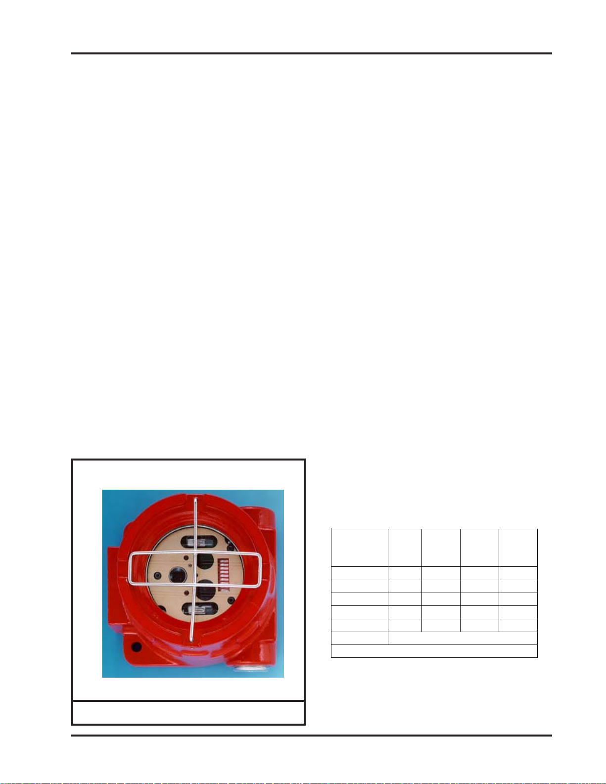
FIGURE 1-1: Model 3100 Series Flame Detector
Model 3100 Series Flame Detector (11/04)
Model
Fire
Rela
y
Fault
Relay
Verify
Relay
Aux.
Relay
3100-01 X X None None
3100-02 X X N/O N/C
3100-03 X X N/C N/O
3100-04 X X N/O N/O
3100-05 X X N/C N/C
3100-06 4-20 mA signal only
Models and Functions
Page: 1
Page 5
Instruction Manual
2. OPERATION
2.1 General
When the Model 3100 Flame Detector is powered
up, the microprocessor checks the configuration
switch settings and configures the detector. The microprocessor then runs a full series of self tests.
After the self test process is complete and all tests
are passed, the detector is ready to detect a fire.
All modes of operation are indicated by two LEDs
located on the front of the detector. Normal Mode
is indicated by a brief flash of the LEDs every 8
seconds. With the device in Normal Mode it is
constantly monitoring the environment and ready
to detect a fire.
When a fire is detected the flame detector will activate the Fire Relay and turn on both LEDs. If the
device is configured for “Latching” Mode the device will remain in Alarm Mode until power is removed. In “Fire Following” Mode the Fire Relay
will reset when the Fire Probability Algorithm determines there is no longer a fire.
The self test system is continuously monitoring the
internal systems. When a fault is detected the Fault
Relay is de-energized. In Fault Mode the LEDs
will flash a code indicating the type of fault. A fault
indication may mean the device is unable to detect
a fire or that a device has become unreliable. (i.e. a
“Voltage Low” fault) For most faults the detector
will return to Normal Mode when the fault condition is corrected.
The Model 3100 Series comes in several versions.
The basic version 3100-01 does not have the Verify
or the Auxiliary Relay systems. The enhanced Models 3100-02, -03, -04 and -05 have the Verify and
Auxiliary Relay systems. These versions represent
the different configurations (Normally Open or
Closed contacts) of the V erify and Auxiliary Relays.
The Auxiliary Relay provides a separate relay output for the Lens Test Fault. The Verify system is
activated when a fire is declared. A V erified Fire is
declared when the conditions of the Verify Fire Algorithm are met. All other functions are the same
as the basic Model 3100-01.
The 3100-06 does not have relay outputs. It uses a
4-20 mA current circuit. The detector's status determines the amount of current flow through the
circuit.
Page: 2
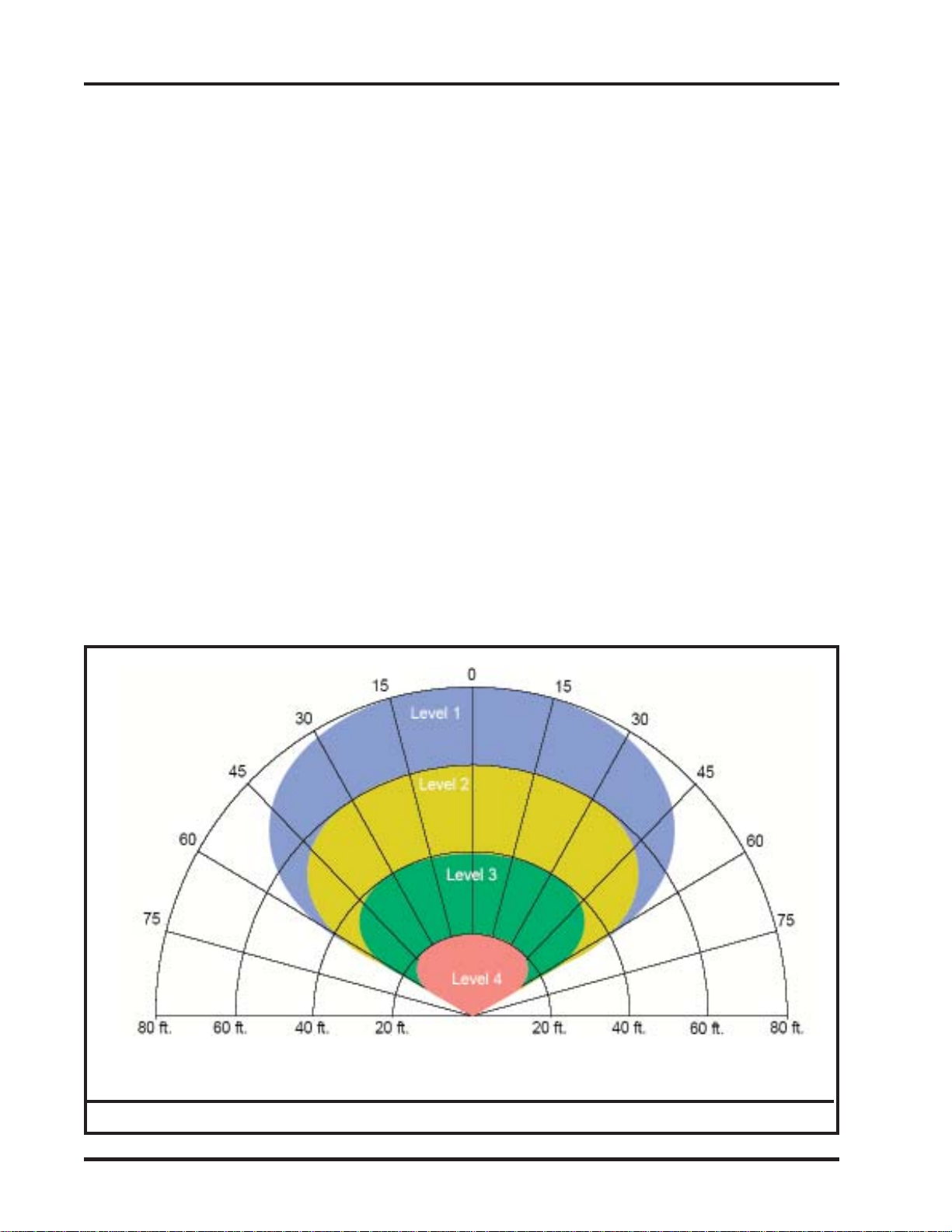
Figure 2-1: Model 3100 Series Field of View
Model 3100 Series Flame Detector (11/04)
Page 6
Instruction Manual
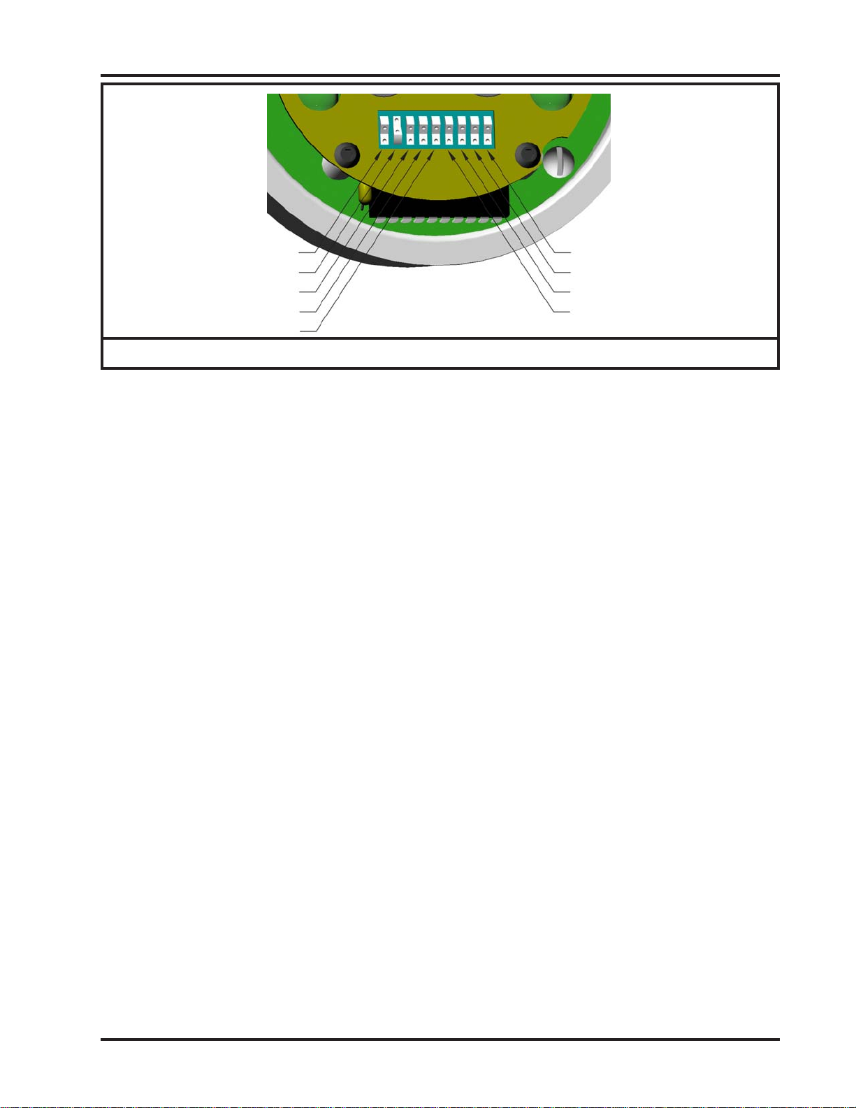
SW1
SW2
SW3
SW4
SW5
SW1 Shown in off position
SW2 Shown in on position
Figure 2-2: Configuration Switches
2.2 Field-of-V iew (See Figure 2-1)
Optical Flame Detectors must be able to “see” the
fire to declare an alarm. Any obstruction between
the detector and the threat area will impair the detectors ability to cover the threat area. An obstruction is anything that is not transparent to the sensor
elements of the detector. UV sensors and some
types of IR sensors cannot see through glass or plastics. The 3100 series of Flame Detectors has a
120° Field of V iew .
When covering a large area the detectors should be
located to provide overlapping fields of view to insure complete coverage.
2.3 Range
The size of fire and type of materials which constitute the threat will affect the detector’s range. Different materials produce different amounts of the
radiant energy used by the detector to “see” the
fire. Also, the range of the detector is a function of
the fire size. Using the square of the distance rule,
if the device will detect a one sq. ft. fire at 60 feet,
to detect a 1/4 size fire (aprox. 6 sq. in.) the devices
must be within 30 feet. The Model 3100 Detector
is optimized to a 1 sq. ft. Kerosene fire at 80 feet
with the sensitivity settings set to maximum sensitivity .
2.4 Environment
All optical flame detectors sense radiant energy at
some frequency or frequencies within their Fieldof-View. Any source which radiates energy at the
same frequency or frequencies used by the detector
SW9
SW8
SW7
SW6
to sense a fire may impact the detector’s ability to
“see” the fire. Care should be taken to minimize
radiant energy sources within the detectors Fieldof-View. Because of the variety of environments
and conditions, a factory trained technician or qualified P.E. should be consulted before deciding on
the location of devices. The Model 3100 Detector
uses an Ultraviolet sensor (180 - 260 nanometers),
an Infrared sensor (.715 - 3.5 microns), and a Visible sensor (480 - 560 nanometers).
2.5 Configuration (See Figure 2-2)
All of the 3100 Series models have field adjustable
configuration switches located on the front face of
the detector. The factory settings are shown in italic
text. The enhanced models have additional configuration options for the Verified Fire.
2.5.1 Sensitivity
All versions have several sensitivity settings
available. The sensitivity settings are 20, 40,
60, and 80 feet. Each setting is optimized to
alarm on a 1 sq. ft. Kerosene fire within 5
seconds. Switches 1 and 2 control the sensitivity. The factory default is 80 feet. (SW1
and SW2 are off.)
Note: Different fuels emit energy at different
rates. For example; a fire involving fuel oil
does not emit energy at the same rate as gasoline. Consequently, the Model 3100 will be
able to respond to a gasoline fire at a little
greater distance than it will to a fuel oil fire.
Similary, a fire involving acetone will be seen
at a greater distance than one involving gaso-
line.
Model 3100 Series Flame Detector (11/04)
Page: 3
Page 7
Instruction Manual
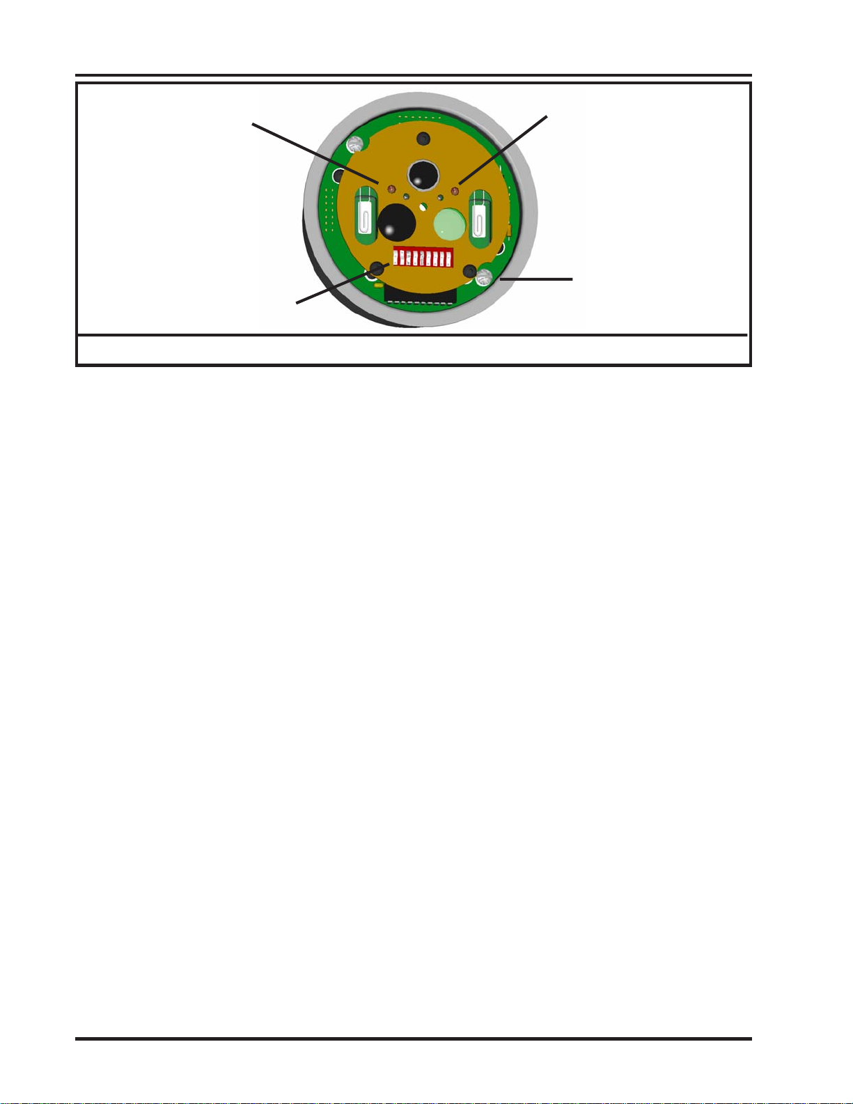
LED 1
(2 locations)
Configuration Switches
Figure 2-3: Model 3100 Series Detector Module (Front)
2.5.2 Verify Control
The Enhanced Model 3100-02, -03, -04, 05 and -06 have the Verified Fire function.
The Verify Control switches allow the user
to select the verify level, disable the verify
function, or make the Verify Relay operate
in parallel with the Fire Relay. The verify
function in enabled when the detector declares an alarm. The verify level sets the
degree of certainty required to declare a verified fire. The lowest level (1) is the lowest
certainty (fastest) and the highest level (6) is
the greatest certainty (slowest) of a fire. The
verify function enables an algorithm which
evaluates the fire signature over time to determine the degree of certainty. When the
degree of certainty exceeds the level set by
the configuration switches a Verified Fire is
declared and the Verify Relay is energized.
Switches 3, 4, and 5 control the verify function. The factory default is verify disabled
and set to level 0. (SW3, SW4 and SW5 are
off.)
2.5.3 Latching Control
The latching controls allow the detector or
individual relay outputs to be set to “Latching” or “Fire Following”. “Latching” causes
the relay to stay energized until power is removed from the detector. “Non-latching” allows the relay to reset (de-energize) when a
flame is not present for a short period of time.
For the detector to be set to "Non-latching"
both Fire Output and Verify Output must be
set to "Non-latching". If either the fire out-
LED 2
Mounting Screw
put or the verify output is set to "Latching"
then the detector will be set to "Latching".
When the detector is set to "Latching" the
LED's will indicate an alarm until the device
is reset regardless of the fire or verify relay
output settings.
The Verify Relay is automatically configured
as “Latching” if the Fire Relay is set to “Latching”. SW6 sets the Fire Relay Output, SW7
sets the Verify Relay Output and SW8 sets
the Detector Mode. To set the detector to
"Non-latching", SW6, SW7 and SW8 must
be set to "Non-latching. The factory defaults
are “Latching” (SW6 and SW7 ar e off.)
2.5.4 Other Configuration Switches
The last configuration switch (SW9) must be
in the off position. The factory default set-
ting is off.
2.6 LED operation (See Figure 2-3)
The status of all versions of the flame detectors can
be determined from the LEDs located behind the
lens on the front of the detector. The LEDs will
flash at intervals or remain on to indicate the detectors status. (Fault Mode, Normal Mode, Alarm
Mode, Verified Fire Mode, and on power up the
Configuration Settings).
2.6.1 Power Up
At power up all versions of the flame detector will begin flashing the LEDs. The LEDs
will flash 8 consecutive patterns which indicates the positions of the configuration
switches. Each pattern indicates the position
Page: 4
Model 3100 Series Flame Detector (11/04)
Page 8
Instruction Manual
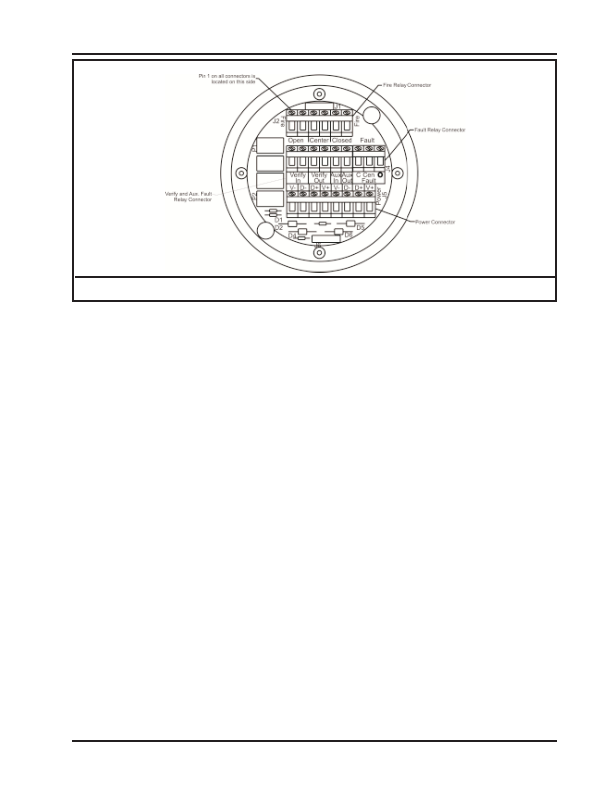
Figure 2-4: Model 3100 Series Detector Module (Back)
(“on” or “off”) of a switch (SW1-SW8).
The first flash pattern indicates the position
of the first switch (SW1), with each consecutive flash indicating the position of the next
switch in order. The flash pattern is as follows: only one LED “on” indicates a switch
in the “off” position, both LEDs “on” indicates a switch in the “on” position. The position of SW9 is not indicated. If SW9 is in
the “on” position the detector will power up
in fault mode.
2.6.2 Normal
In Normal Mode the LEDs will flash briefly
every 8 seconds. Whenever the device is in
any other mode the “flash every 8 seconds”
is suspended until the detector returns to
Normal Mode.
2.6.3 Fire
When any version of the Model 3100 declares a fire, both LEDs will come “on” and
stay “on”. If the detector is set to "Latching"
the LED's will remain "on" and stay "on"
until the detector is powered down. If the
detector is set to "Non-latching" the LED's
will reset to "Normal Mode" when the fire is
no longer being detected. If the Verified Fire
is declared (Verify Fire is only on the Enhanced Models) the LEDs will blink “off”
briefly every second. If the detector is set to
"Latching" the LED's will remain in this state
until the detector is powered down.
2.6.4 Fault
When the detector has power and is in Fault
Mode LED1 (the left LED when facing the
detector with the configuration switches below the LEDs) will be on for 5 seconds while
the LED2 (the right LED) will be off see
Table B.4 on page 12. The LED will turn
"off" and LED 2 will begin flashing 1/2 seconds "on" and 1/2 second "off" a number of
times. The number of times LED2 flashes
indicates the type of fault. This cycle is repeated until the fault is corrected. Only the
highest number fault is indicated. Once a
fault is corrected the next highest level fault
will be indicated until all faults are cured.
Except for fault level 2 and 3, a fire indication will override a fault indication. The detector is disabled if a fault 2 or 3 is indicated.
2.7 Relay operation (See Figure 2-4)
The Model 3100-01 has two relays, the enhanced
Models 3100-02, -03, -04 and -05 have four relays.
The function of the Fire and Fault Relays is the
same on all models. The Verify Relay and Aux.
Relay is only available on the enhanced models. All
relay connections are made at the connectors located on the back of the flame detector module.
2.7.1 Fire Relay
The Fire Relay will energize whenever the
detector declares a fire. Depending on the
configuration setting, the relay will: “Latch-
Model 3100 Series Flame Detector (11/04)
Page: 5
Page 9

Instruction Manual
ing” - remain energized until power is removed, ”Fire Following” - de-energize a short
time after the fire is no longer detected. The
“J2” connector provides connections for both
normally open contacts and normally closed
contacts on the Fire Relay .
2.7.2 Fault Re lay
The Fault Relay is a normally energized relay . It will de-energize when a Fault occurs.
This means the detectors Fault Relay is in
the “Fault” state when the detector has no
power, and remains in the “Fault” state until
the detector is powered up and operating normally. The “J4” connector provides both
normally open contacts and normally closed
contact on the Fault Relay .
2.7.3 Verify Relay
The Verify Relay will energize when a “V erified Fire” is declared. Depending on the configuration the relay will: “Latching” - remain
energized until power is removed, “Fire Following” - de-energize a short time after the
fire is no longer detected. Further, the “Verify
Control” configured to Level 0 will disable
the V erify Relay , and Level 7 causes the Verify
Relay to operate in parallel with the Fire Relay. The connector labeled “Verify In” and
“Verify Out” provides connections for normally open contacts on the 3100-02 and 310004 or normally closed contacts on the 310003 and 3100-05. The configuration of Normally Open or Normally Closed contacts is
fixed and can only be changed by the factory.
3100-02 and 3100-05 models. The configuration of Normally Open or Normally Closed
contacts is fixed and can only be changed by
the factory .
2.7.5 4-20 mA Operation
The 3100-06 uses a 4 to 20 mA current draw
circuit to indicate Fault, Fire, Verify Fire and
Normal Mode. The current draws are as follows:
Fault Mode: 0 mA
Normal Mode: 4 mA
Alarm Mode: 12 mA
V erify Mode: 20 mA
The 4-20 circuit is connected across the J2
connector at contact 6 and 7 where connection 6 is the negative side and connection 7 is
the positive side. Additionally, a jumper between contacts 7 and 8 must be made.
2.7.4 Auxiliary Fault
The Aux. Relay is energized whenever the
detector fails the “Lens Check” test. This
fault indicates the detectors inability to “see”
a fire. Normally , cleaning the lens will clear
this fault. Because a dirty lens is the most
common type of fault, a separate indicator
connected to this relay will simplify maintenance. The connector labeled “Aux In” and
“Aux Out” provides connections for Normally
Open contacts on the 3100-03 and 3100-04
models or Normally Closed contacts on the
Page: 6
Model 3100 Series Flame Detector (11/04)
Page 10

Instruction Manual
3.0 INSTALLATION
3.1 General Precautions
All wiring and installation must be done in accordance with the NFP A 70 and 72 standards and must
comply with any codes specific to the application or
location. Contact the local authority having jurisdiction and the company safety engineer for information on codes which may apply .
3.2 Housing and Conduit
3.2.1 Mounting the Housing
The housing is mounted by using the two
0.3” diameter holes located in ears on the
back of the housing. The two conduit holes
located on the side of the housing are not to
be used for mounting. The detector should
be mounted securely to a flat surface. The
mounting location must be strong enough to
support the detectors 3 lb. weight. Although
the detector is not vibration sensitive the detector should not be exposed to excessive vibration. "(The detector has been tested to
meet the vibration standard set in FM’s Approval Standard Class 3820, Sept. 1979.
(.022" displacement, 10 Hz to 30 Hz sweep
cycled at 2 cpm for 4 hours)"
3.2.2 Installing the Conduit and Wiring
Mount a “Seal Off” at the housing into the
3/4” NPT conduit(s) located on either side
of the housing. Connect the conduit to the
“Seal Off”. If one of the conduit openings is
not used insert a sealing plug into the unused
opening. Run the wires through the conduit,
“Seal Off”, and into the housing. The ends
of the wire should extend several inches (at
least 2” to 4”) beyond the front of the housing base.
3.3 Connection (See Appendix C for information
regarding connection to various systems)
All connections are made on the back of the Model
3100 Flame Detector Module. Remove the housing
cover from the housing base. Loosen the two slotted head captive screws located on the top of the
PC board. Lift the Detector Module out of the
housing base. Strip and connect the wires to the
connectors located on the back of the Detector
Module.
3.3.1 Power
Power for the 3100-01, -02, -03, -04 and 05 flame detector is connected to the J5 connector labeled “Power”. Connect the negative wire to PIN 1. Connect the positive (24
VDC) wire to PIN 4.
Power for the 3100-06 detector connected
to the J2 connector. Connect positive wire
at 4. Connect negative wire at pin 1. Pins 2
and 3 should be left open.
3.3.2 Fire Relay
The Fire Relay has two internal connection
points. Either or both may be used. The
Fire Relay connector, labeled “FIRE”, has
connection points for Normally Open, Normally Closed, and Common. The Normally
Open connections are labeled “Open”, the
Common contacts are labeled “Com”, and
the Normally Closed contacts are labeled
“Closed”.
3.3.3 Verify Relay
The Verify Relay has two internal connection points. Either or both may be used. The
Verify Relay connector is located between
the Power and Fire relay connectors. The
connection points are labeled “V erify In” and
“V erify Out”. The V erify relay is configured
for Normally Open (3100-02 and 3100-04),
or Normally Closed (3100-03 and 3100-05)
operation at the factory .
3.3.4 Fault Re lay
The Fault Relay connector is labeled “Fault”.
The Normally Open connection is labeled
“O”, the Common connection is labeled
“Com”, and the Normally Closed connection is labeled “C”. The Fault Relay is a
normally energized relay. When the detector has no power the Normally Open contact
is closed and the Normally Closed contact is
open.
Model 3100 Series Flame Detector (11/04)
Page: 7
Page 11

Instruction Manual
3.3.5 Auxiliary Relay
The Auxiliary Relay connector is located between the Power and Fire Relay connectors.
The connection points are labeled “Aux In”
and “Aux Out”. The Aux. Relay is configured for Normally Open (3100-03 and 3100-
04), or Normally Closed (3100-02 and 3100-
05) operation at the factory .
3.3.6 4-20 mA Connections
The 4-20 mA connections are connected at
the J2 connections The positive side of the
4-20 mA circuit is connected to Pin 7 and
negative side to Pin 6.
3.4 T esting
The Model 3100 Flame Detector uses ongoing selftest functions which will indicate a fault if any of
the functions fail to pass. If an end to end test is
required, a 1 sq. ft. pan with 1 inch of water and 1/
8 inch of kerosene set at the max. distance set by
the sensitivity settings may also be used. The detector should alarm within 5 seconds of ignition of the
fire.
The Model 3140 Flame Tester is also available. It
simulates a UV/IR flame signature by emitting a
steady state UV signal and modulated IR signal at a
flicker frequency of 5 to 10 Hs.
NOTE: Because of the danger involved with
fire testing all safety precautions
must be observed.
4.0 MAINTENANCE
The self-test functions eliminate the need for most
regular maintenance procedures. If a detector indicates a fault, use the troubleshooting section of this
document to correct the fault. Contact the local
“authority having jurisdiction” or consult the local
codes for any maintenance they may require for the
type of system installed.
4.1 Lens Cleaning
The most common fault is a Lens T est Fault. Regular cleaning of the Lens will eliminate this type of
fault. The frequency will depend on the cleanliness
of the area where the detector is installed and how
the detector is mounted. A detector which is pointed
down should require less cleaning than one that is
pointed up. An area which has lots of oil particulates or dust will require more frequent cleaning than
one that is oil and dust free. The frequency of the
Lens T est Fault will indicate how often cleaning is
necessary . If the device is failing the “Lens test” to
often it may be necessary to install a dust shroud,
realign the detector, or change the detectors mounting location.
To clean the lens: Wipe the lens surface and grill
with a clean lint free cloth. If more extensive cleaning is required use denatured or Isopropyl alcohol
and a clean lint free cloth. Do not use any silica
based solvents. (Most common glass cleaners are
silica based and should not be used to clean the
lens.)
Page: 8
Model 3100 Series Flame Detector (11/04)
Page 12

Instruction Manual
5.0 TROUBLESHOOTING
The flame detector has several built-in self test
mechanisms which verify function and calibration.
The following procedure covers most faults and
problems which may occur during installation or
during the course of normal operation.
5.1 No LED blink or erratic LED blink
With power connected to the detector the LEDs
on the front of the detector module should begin
blinking and blink about every 8 seconds. If they
do not blink or blink in an abnormal fashion.
1. Remove the detector module from the housing.
2. Check voltage at power connector (J5, Pin 1
and Pin 4) Pin 1 should be the connected to
negative, and Pin 4 should be positive. Voltage should be between 15 and 32 volts DC.
3. If Main power is correct and the detector is
not indicating a fault. The detector module
should be returned to the factory .
5.2 Detector Indicates Fault
Use the fault table (Table B.4, page 17) to determine what type of fault is occurring and see appropriate section below to correct. If the corrective actions listed below do not correct the fault,
contact the factory for further diagnostic instructions or instructions on returning the detector for
servicing. (Ref. 2.6.4) or repeat.
5.2.4 Fault T ype 4 - “Voltage Low Fault”
The input voltage is below 15 VDC. Remove the Detector Module from the housing. W ith the detector connected to power,
measure the voltage between Pin 1 and Pin
4 on the Power connector (J5). The voltage should be between 15 - 32 VDC. If the
voltage is out of range check external wiring and power supply . There should not be
more than 1 volt of AC ripple at 24 VDC.
If the measured voltage is in range and there
is no AC ripple, contact the factory for return and service information.
5.2.5 Fault T ype 5 - “Photo Sensor Fault”
One of the Photo Sensors (Visible or IR)
did not pass the internal self test. If both
sensors are clean. The fault may be in the
sensors or the self test circuit. Contact the
factory for further diagnostic information.
5.2.6 Fault T ype 6 - “Relay Fault”
One of the Relay’s coil circuits is open.
There is no corrective action. Contact the
factory for return and service information.
5.2.7 Fault Type 7 - “V oltage High”
The Detector was exposed to an input voltage above 32 Volts. There is no corrective
action. Contact the factory for return and
service information.
5.2.1 Fault T ype 1 - “Lens Test Fault”
Clean lens and grill per section 4.1. Reset
the detector (remove and replace power).
If the fault persists it may indicate a bad
UV tube or UV source tube, factory service is required.
5.2.2 Fault T ype 2 - “Configuration Fault”
Dip Switch SW9 is “ON”. SW9 should be
set to off for normal operation. Change
SW9 to “OFF” and reset detector.
5.2.3 Fault T ype 3 - “Calibration Fault”
Calibration constants have been corrupted.
Factory service is required.
Model 3100 Series Flame Detector (11/04)
5.2.8 Fault T ype 8 - “Temperature Out of
Range”
The internal measured temperature was below -40° C or above 85° C. There is no
corrective action. Contact the factory for
return and service information.
5.3 Device appears to operate normally but will
not alarm to a fire.
When the detector declares an alarm two things
should happen. One, both the LEDs on the front
of the detector should come on. Two, the fire relay should energize. Check the dip switch settings. (SW1, SW2, SW8, and SW9 should be off
SW3 - SW7 have no impact.) Connect an ohm
meter across the Fire relay connections at the “Fire”
connector (Pin 1 and Pin 3 of J2). Run a fire test
per section 3.4.
Page: 9
Page 13

Instruction Manual
1. If the relay closes (0 ohms on the meter) and
the LEDs come “on” the detector is operating
normally. Check external alarm initiating cir cuit wiring.
2. If the relay closes and the LEDs remain off,
or the relay remains open and the LEDs come
on, the detector needs factory service.
3. If the relay remains open and the LEDs remain off, contact the factory for further diagnostic information.
Page: 10
Model 3100 Series Flame Detector (11/04)
Page 14

Instruction Manual
6.0 SPECIFICA TIONS
Sensitivity: 1 ft. sq. Pan fire on axis @ 80 feet within 5 seconds (using standard fuel)
Switch selectable form 20 to 80 feet to a 1 sq. ft. kerosene fire
Field of View: 120 degree cone
Responsivity: UV - 185 to 260 nm, IR - 0.715 to 3.5 microns, Visible - 480 to 560 nm
Input voltage: 15 to 32 volts, typically 24 volts
Current Draw: @24 Volts DC: 72 mA normal mode, 82 mA alarm mode
T emperature Range:
Operating: -40oF to 185oF (-40oC to 85oC)
Storage: -67
LEDs: Display switch settings, fault type, fire and verified fire information
Relays:
Model 3100-01: Fire and Fault Relays
3100-02, -03, -04,
-05 Enhanced Relay
Models:
4-20 mA Outputs
3100-06: 0 mA - Fault, 4 - mA - Normal Mode, 12 mA - Alarm, 20 mA - Verified Fire
Connections: Screw terminals, 14 - 22 AGW wire size
Enclosure: Copper-free Cast Aluminum with epoxy finish, Conduits: T wo 3/4 inch NPT feed-
Hazardous area
classification: NEMA 4X, Explosion Proof
Dimensions: 5.4 x 4.8 x 3.7 inches (13.7 x 12.2 x 9.4 cm)
Weight: 3 lbs (1.3 Kg)
o
F to 230oF(-55oC to 110oC)
120 VAC, 1.0 amp @ 24 VDC resistive, normally open and normally closed contacts,
latching or fire-following modes
Fire, Fault, V erify and Aux Relays
0.5 amp @ 120 VAC, 1.0 amp @ 24 VDC resistive, normally open and normally
closed contacts are available.
through hubs
Class I, Div. 1 and 2, Groups B, C, D, Class II and III, Div. 1 and 2, Groups E, F, G
7.0 LIMITED W ARRANTY
SIERRA MONITOR CORPORATION warrants its
products to be free from defects in workmanship or
material under normal use and service for two years
after date of shipment. SMC will repair or replace without charge any equipment found to be defective during
the warranty period. Final determination of the nature
and responsibility for defective or damaged equipment
will be made by SMC personnel.
All warranties hereunder are contingent upon proper use
in the application for which the product was intended
and do not cover products which have been modified or
repaired without SMC approval or which have been subjected to accident, improper maintenance, installation
or application, or on which original identification marks
have been removed or altered. This Limited Warranty
also will not apply to interconnecting cables or wires,
consumables (ie. calibration gases, batteries, sensors),
Model 3100 Series Flame Detector (11/04)
nor to any damage resulting from battery leakage.
In all cases SMC’s responsibility and liability under this
warranty shall be limited to the cost of the equipment.
The purchaser must obtain shipping instructions for the
prepaid return of any item under this warranty provision and compliance with such instruction shall be a
condition of this warranty .
Except for the express warranty stated above, SMC disclaims all warranties with regard to the products sold
hereunder including all implied warranties of merchantability and fitness and the express warranties stated herein
are in lieu of all obligations or liabilities on the part of
SMC for damages including, but not limited to, consequential damages arising out of/or in connection with
the use or performance of the product.
Page: 11
Page 15

Instruction Manual
APPENDIX A
Figure A-1: Model 3100 Series Exploded View
Page: 12
Figure A-2: Model 3100 Series Dimensions
Model 3100 Series Flame Detector (11/04)
Page 16

Instruction Manual
Figure A-3: Model 3100 Series Common Wiring Connections
Model 3100 Series Flame Detector (11/04)
Page: 13
Page 17

Instruction Manual
Factory jumpers
are used to set
NC or NO
connections
Figure A-4: Model 3100 Series (Enhanced) Wiring Connections
Page: 14
Model 3100 Series Flame Detector (11/04)
Page 18

APPENDIX B
T ABLES
B.1 Dip Switch Settings
B.1.1 Sensitivity
Sensitivity SW1 SW2 Level
20 Foot ON ON 4
40 Foot OFF ON 3
60 Foot ON OFF 2
80 Foot OFF OFF 1
B.1.2 Verify Control (3100-02, -03, -04 and -05 Models only)
Verify Description SW3 SW4 SW5
Level 0 V erify = Fire OFF OFF OFF
Level 1 Min. V erify (shorter) ON OFF OFF
Level 2 Min. V erify (shorter) OFF ON OFF
Level 3 Min. V erify (shorter) ON ON OFF
Level 4 Min. V erify (shorter) OFF OFF ON
Level 5 Min. V erify (shorter) ON OFF ON
Level 6 Max. Verify (longer) OFF ON ON
Level 7 V erify Disabled ON ON ON
Instruction Manual
B.1.3 Fire Output“Latching” Control
Fire Output Description SW6
Latching Alarm until Power down Reset OFF
Following Alarm until no fire (.5 to 10 sec.) O N
B.1.4 Verify Relay “Latching” Control (3100-02, -03, -04 and -05 Models only)
Verify Relay Description SW7
Latching Alarm until Power down Reset OFF
Following Alarm until no fire (.5 to 10 sec.) ON
B.1.5 Detector "Non-Latching" Control
SW6, SW7 and SW8 must be on for the detector to be "Non-Latching".
B.1.6 Factory Use Only
SW8 and SW9 must be in the OFF position for normal operation. They are used for factory
calibration and testing.
Model 3100 Series Flame Detector (11/04)
Page: 15
Page 19

Instruction Manual
B.2 Connectors
B.2.1 Fire Relay Connector
(J2) Fire Relay Description
Pin 1 (Left Most) & Pin 2 Normally Open Side of Relay
Pin 3 & Pin 4 (Middle) Common or Center Side of Relay
Pin 5 & Pin 6 (Right Most) Normally Closed Side of Relay
B.2.2 V erify and Aux. Fault Connector
(J3) V erify/Aux. Description
Pin 1 (Left Most) & Pin 2 Verify Relay Common Side of Relay
Pin 3 & Pin 4 V erify Relay NO or NC Side of Relay
Pin 5 Aux. Fault Relay Common Side of Relay
Pin 6 (Right Most) Aux. Fault Relay NO or NC Side of Relay
B.2.3 Fault Connector
(J4) Fault Relay Description (Normally Energized State)
Pin 1 (Left Most) Normally Closed Side of Relay
Pin 2 (Middle) Common Side of Relay
Pin 3 (Right Most) Normally Open Side of Relay
B.2.4 Power/Communications Connector
(J5) Power/Comm. Description
Pin 1 (Left Most) & Pin 5 Power (DC -)
Pin 2 & Pin 6 Communication RS 485 (-)
Pin 3 & Pin 7 Communication RS 485 (+)
Pin 4 & Pin 8 (Right Most) Power (DC +)
B.2.5 3100-06 Connectors
(J2) Connector Description
Pin 1 (Left Most) Power (DC -)
Pin 2 Communication RS 485 (-)
Pin 3 Communication RS 485 (+)
Pin 4 Power (DC +)
Pin 5 4-20mA Negative
Pin 6 4-20mA Positive
Pin 7 to Pin 8 Jumper (Right Most) Enables 4-20 mA
Page: 16
Model 3100 Series Flame Detector (11/04)
Page 20

Instruction Manual
B.3 V erify/Aux. Relay Configurations
Model # V erify Relay Aux. Relay
3100-02 Open Contacts Closed Contacts
3100-03 Closed Contacts Open Contacts
3100-04 Open Contacts Open Contacts
3100-05 Closed Contact Closed Contacts
B.4 Fault Table
Fault # Fault Label Description
1 Lens T est Fault UV sensors didn’t detect enough UV from the internal UV source.
2 Configuration Fault SW9 is “ON” or a failed program
3 Calibration Fault Device is out of calibration
4 Volt. Low Input Voltage is below 15 VDC
5 Photo. Sensor Fault IR or V isible sensor failed to detect internal test source.
6 Relay Fault Relay coil circuit is open.
7 Volt. High Input Voltage was above 32 VDC
8 Temp. Out of Range Internal device temperature went below -40° C or above 85° C.
B.5 False Alarm S timuli Table
F ALSE ALARM RESPONSE
This table shows the detectors ability to tolerate both modulated and unmodulated false alarm stimuli.
False Alarms Source Distance Unmodulated Modulated
Resistive Electric Heater 1320 W att 6 Feet No Response No Response
Fluorescent Lights (2) 40 W att Bulbs 6 Feet No Response No Response
Halogen Light 500 W att 10 Feet No Response No Response
Incandescent Light 100 W att 6 Feet No Response No Response
Arc W elder 50 Watt 25 Feet No Response No Response
Direct Sunlight 93 million miles No Response No Response
B.6 Fire and False Alarm Stimuli T able
Model 3100 detector response to a fire while exposed to a variety of radiant energy sources.
False Alarms Distance to False Distance Response Time to
Source Alarm Source to Fire Fire
Resistive Electric Heater 1320 W att 6 Feet 6 Feet Less than 5 sec.
Florescent Lights (2) 40 W att Bulbs 6 Feet 6 Feet Less than 5 sec.
Halogen Light 500 W att 10 Feet 6 Feet Less than 5 sec.
Incandescent Light 100 Watt 6 Feet 6 Feet Less than 5 sec.
Arc Welder 50 Watt 25 Feet 6 Feet Less than 5 sec.
Direct Sunlight 93 million miles 6 Feet Less than 5 sec.
Model 3100 Series Flame Detector (11/04)
Page: 17
Page 21

Instruction Manual
B.7 Detector Response to Fuels Table
Fuel Distance Fire Size Response Time
Heptane 80 Feet 1 Square Foot Less than 3 sec.
Silane 50 Feet 18 inch jet Less than 3 sec.
Hydrogen 15 Feet 18 inch jet Less than 5 sec.
Kerosene 75 Feet 1 Square Foot Less than 5 sec.
Page: 18
Model 3100 Series Flame Detector (11/04)
Page 22

APPENDIX C -- WIRING CONNECTIONS
Instruction Manual
Model 3100 Series Flame Detector (11/04)
Page: 19
Page 23

Instruction Manual
Index
A
Alarm
Mode 2, 4
Verified 2
Auxiliary
Relay 1, 2, 5, 6, 7
C
Cleaning 8
Conduit 7, 11
Configuration
Relay Control 4
Sensitivity 3
Switches 3, 4
Verify Control 4
Configuration Switches 5
Connection 7
Connector
Aux. 6, 7
Fault 6, 7
Fire 6, 7
Power 7
Verify 6, 7
Connectors 5, 16
T ype 1 1
D
Detector Module 7
F
Fault 5
Auxiliary 1, 6
Lens Test 1, 8
Relay 1, 2, 6, 7
Field-of-View 1, 3
Fire 5
Relay 1, 2, 4, 6, 7, 16
Testing 8
Verify 1
Fire Following 2, 4, 6
Fire Probability 2
H
Housing 1, 7
L
Latching 2, 4, 6, 15
LEDs 2, 4, 5, 20
Lens 8
Lens Test 1, 2
M
Mode
Alarm 2, 4, 5
Fault 5
Fire Following 2
Latching 2
Normal 2, 4
Verified Fire 4
N
Normal Mode 2, 4, 5
Normally Closed 2, 6, 7
Normally Open 2, 6, 7
P
Power 4, 7, 16, 19
R
Range 3
Relay 5
Aux. 2, 5, 6, 7, 17
Auxiliary 1
Control 4
Fault 1, 2, 6, 7
Fire 1, 2, 4, 6, 7
Fire Following 6
Latching 6
Normally Closed 2
Normally Open 2
Verify 4, 5, 6, 7, 17
S
Seal Off 7
Sensitivity 3
Field-of-View 1
Range 3, 15
Sensor 3
Square of the distance rule 3
Switches
Configuration 3, 4, 15
Sensitivity 3, 15
SW8, SW9 4
Verify Control 4, 15
I
Infrared 3
Page: 20
Model 3100 Series Flame Detector (11/04)
Page 24

T
Testing 8
U
Ultraviolet 3
V
Verified Fire 2, 4, 5, 6
Verify
Control 4
Relay 2, 4, 5, 6, 7, 15
Verify Control 6, 15
Versions 2
Visible 3
W
Wiring 7
Instruction Manual
Model 3100 Series Flame Detector (11/04)
Page: 21
 Loading...