

Page 1

MODEL 5100-XX-IT
IT Series
TOXIC GAS SENSOR MODULE
Version 3.00A
APPLICABILITY & EFFECTIVITY
Effective for all Model 5100-XX-IT Modules manufactured after December 1, 2011.
5100-03-IT
5100-04-IT
5100-05-IT FM Approved
5100-06-IT
5100-08-IT
5100-10-IT
5100-12-IT
5100-21-IT
5100-25-IT
5100-26-IT
5100-88-IT
Instruction Manual Part Number T12020
Rev. D
Page 2

Model 5100-XX-IT Toxic Gas Sensor Module
FM PERFORMANCE APPROVAL
ONLY THE FOLLOWING ITEMS, FUNCTIONS AND OPTIONS ARE FM* APPROVED
Model 5100-05-IT Hydrogen Sulfide Gas Sensor Module
Sensor Module
Model 5100-05-IT-AL Sensor Module - Hydrogen Sulfide, Aluminum
Model 5100-05-IT-SS Sensor Module - Hydrogen Sulfide, Stainless Steel
Calibration Equipment
Model 1250-01 Gas Sensor Calibration Kit, Type A
Model 1260-05 Hydrogen Sulfide in N2, 25 ppm Gas Cylinder
Model 1260-45 Hydrogen Sulfide in N2, 10 ppm Gas Cylinder
Model 5358-01 Calibration Adapter
Notes:
1) Apparatus must be installed in accordance with National Electrical Code.
2) FM Comments
*FM Approvals, a subsidiary of FM Global
Project# 3034435
Page 3

Model 5100-XX-IT Toxic Gas Sensor Module
TABLE OF CONTENTS
PRODUCT DESCRIPTION ................................................................................................................................. 1
1.
1.1 GENERAL ........................................................................................................................................................ 1
1.2 PRODUCT CONFIGURATION ........................................................................................................................ 2
1.3 THEORY OF OPERATION .............................................................................................................................. 2
1.4 MODES OF OPERATION ................................................................................................................................ 2
1.5 MECHANICAL ................................................................................................................................................. 3
1.6 INTERCONNECT WIRING .............................................................................................................................. 3
1.7 POWER REQUIREMENTS ............................................................................................................................. 3
2. CAUTIONS & WARNINGS ................................................................................................................................. 6
2.1 INTRODUCTION ............................................................................................................................................. 6
2.2 GAS SENSOR MODULES - GENERAL .......................................................................................................... 6
2.3 WIRING ............................................................................................................................................................ 6
2.4 CALIBRATION FREQUENCY ......................................................................................................................... 6
3. QUICK START .................................................................................................................................................... 7
3.1 OVERVIEW ...................................................................................................................................................... 7
3.2 WIRING ............................................................................................................................................................ 7
3.3 MODULE INSTALLATION ............................................................................................................................... 7
3.4 TRANSMITTER INSTALLATION .................................................................................................................... 7
3.5 START-UP & OPERATION ............................................................................................................................. 7
3.6 ZERO STABILIZATION ................................................................................................................................... 7
4. INSTALLATION .................................................................................................................................................. 8
4.1 SENSOR MODULE LOCATIONS ................................................................................................................... 8
4.2 WIRING ............................................................................................................................................................ 9
4.3 ENCLOSURE INSTALLATION ...................................................................................................................... 10
4.4 TRANSMITTER AND SENSOR INSTALLATION ......................................................................................... 10
4.5 MODULE ADDRESS SWITCH ...................................................................................................................... 12
5. OPERATION ..................................................................................................................................................... 18
5.1 INTRODUCTION ........................................................................................................................................... 18
5.2 DATA ENTRY KEYPAD ................................................................................................................................ 18
5.3 MAIN MENU .................................................................................................................................................. 19
5.4 SET-UP .......................................................................................................................................................... 20
5.5 MAINTENANCE SUB-MENU ........................................................................................................................ 23
6. CALIBRATION .................................................................................................................................................. 24
6.1 CALIBRATION FREQUENCY ....................................................................................................................... 24
6.2 CALIBRATION PREPARATION .................................................................................................................... 24
6.3 CALIBRATION GAS DELIVERY METHODS ................................................................................................. 24
6.4 SENSOR EXPOSURE TO GAS .................................................................................................................... 24
6.5 CALIBRATION SUB-MENU........................................................................................................................... 25
7. SERVICE ........................................................................................................................................................... 27
7.1 SENSOR MODULE CONFIGURATION ........................................................................................................ 27
7.2 ENCLOSURE REPLACEMENT .................................................................................................................... 27
7.3 TRANSMITTER REPLACEMENT ................................................................................................................. 28
7.4 SENSOR REPLACEMENT ............................................................................................................................ 28
7.5 INSTALLATION INSPECTION ...................................................................................................................... 28
7.6 INSPECTION AND TROUBLESHOOTING GUIDE ....................................................................................... 29
Contents
Page 4

Model 5100-XX-IT Toxic Gas Sensor Module
8. APPENDICES ................................................................................................................................................... 30
8.1 APPENDIX A: SPECIFICATIONS.................................................................................................................. 30
8.2 APPENDIX B: MODEL NUMBERS & PARTS LIST ....................................................................................... 33
8.3 APPENDIX C: LIMITED WARRANTY ............................................................................................................ 34
8.4 APPENDIX D: REMOTE SENSOR DRAWING ............................................................................................. 35
8.5 APPENDIX E: MODBUS MEMORY MAP ...................................................................................................... 36
8.6 APPENDIX F: HART ...................................................................................................................................... 37
8.7 APPENDIX G1: 5100-25-IT GAS SENSOR MODULE ................................................................................... 44
8.8 APPENDIX G2: 5100-26-IT GAS SENSOR MODULE ................................................................................... 48
8.9 APPENDIX H: 5100-88-IT DIMENSIONS .......................................................................................................... 49
8.10 APPENDIX I: 5100-05-IT FM PERFORMANCE APPROVAL ........................................................................ 50
8.11 APPENDIX J: 5100-XX-IT SIL-2 CERTIFICATES .......................................................................................... 52
8.12 APPENDIX K: 5100-05-IT ATEX CERTIFICATE ........................................................................................... 55
LIST OF FIGURES
Figure 1 - 1: Model 5100-XX-IT Toxic Gas Sensor Module – Mounting Options ..................................................... 4
Figure 1 - 2: Model 5100-05-IT-S1 (and S2) Toxic Gas Sensor – Stainless Steel Enclosure, Dimensions ............ 4
Figure 1 - 3: Model 5100-05-IT-A1 (and A2) Toxic Gas Sensor – Cast Aluminum Enclosure, Dimensions .......... 5
Figure 4 - 1: Typical Mounting Options .................................................................................................................... 8
Figure 4 - 2: Transmitter Face Plate ....................................................................................................................... 12
Figure 4 - 3: Interface Board Connectors ............................................................................................................... 13
Figure 4 - 4: RS-485: Termination, BIAS Jumper................................................................................................... 13
Figure 4 - 5: mA Circuit Types ................................................................................................................................ 14
Figure 4 - 6: 4-20 mA Circuit Type Connections for 5100-XX-IT ........................................................................... 15
Figure 4 - 7: Wiring Connections for Modbus and Sentry Interface ....................................................................... 16
Figure 4 - 8: Wiring Connections for Remote Alarm Reset .................................................................................... 17
Figure 5 - 1: Face Plate with Operator Key Pad ..................................................................................................... 18
Figure 6 - 1: Model 5358-01 Calibration Adapter ................................................................................................... 24
Figure 7 - 1: Module Components .......................................................................................................................... 27
Figure 8 - 1: Remote Sensor Drawing .................................................................................................................... 35
Figure 8 - 2: HART ................................................................................................................................................. 37
Figure 8 - 3: 4-20 mA Circuits Types 5100-XX-IT – Connections - HART ............................................................. 38
Figure 8 - 4: Module Components .......................................................................................................................... 44
Figure 8 - 5: Sensor Assembly – Exploded View ................................................................................................... 46
Figure 8 - 6: Model 5100-25-IT-A1 (& A2) and Model 5100-26-IT-A1 (& A2) ........................................................ 47
Figure 8 - 7: Model 5100-25-IT-S1 and Model 5100-26-IT-S1 ............................................................................... 47
Figure 8 - 8: Model 5100-88-IT-A1 Dimensions ..................................................................................................... 49
Figure 8 - 9: ATEX .................................................................................................................................................. 55
LIST OF TABLES
Table 4 - 1: Specific Graities .................................................................................................................................... 8
Table 4 - 2: Minimum Wire Gauges ........................................................................................................................ 10
Table 4 - 3: Sensor Module Address Switch Positions .......................................................................................... 12
Table 5 - 1: Master Menu ....................................................................................................................................... 19
Table 5 - 2: Operation Display Values .................................................................................................................... 19
Table 5 - 3: Set-Up Configuration ........................................................................................................................... 21
Table 5 - 4: Maintenance Menu .............................................................................................................................. 23
Table 6 - 1: Calibration ........................................................................................................................................... 25
Table 8 - 1: Modbus Memory Map ......................................................................................................................... 36
Contents
Page 5

Model 5100-XX-IT Toxic Gas Sensor Module
1. PRODUCT DESCRIPTION
1.1 GENERAL
The Model 5100-XX-IT Toxic Gas Sensor Module is a smart transmitter and member of the IT Series family
and it offers a broad array of features including:
• Integral alphanumeric LED display
• Up to 180 day calibration frequency
• FM Approval for performance and safety
• SIL-2 Certified
• Optional integral alarm relays (3)
• 4-20 mA output
• Modbus
• SMC Sentry interface
• Optional HART interface
®
RTU interface
• 316 Stainless steel enclosure option
• Remote sensor option
• Low maintenance and operation costs
• ATEX Approval (5100-05-IT)
The 5100-XX-IT is designed and approved for installation and operation in hazardous locations.
Members of the 5100-XX-IT Series Toxic Gas family include:
• 5100-03-IT Oxygen Gas Sensor Module
• 5100-04-IT Carbon Monoxide Gas Sensor Module
• 5100-05-IT Hydrogen Sulfide Gas Sensor Module
• 5100-06-IT Chlorine Gas Sensor Module
• 5100-08-IT Chlorine Dioxide Gas Sensor Module
• 5100-10-IT Sulfur Dioxide Gas Sensor Module
• 5100-12-IT Nitrogen Dioxide Gas Sensor Module
• 5100-21-IT Hydrogen Chloride Gas Sensor Module
• 5100-25-IT Ammonia Gas Sensor Module
• 5100-26-IT Hydrogen Fluoride Gas Sensor Module
• 5100-88-IT Carbon Dioxide Gas Sensor Module
®
Registered trademark of Schneider Electric
Page: 1
Page 6

Model 5100-XX-IT Toxic Gas Sensor Module
1.2 PRODUCT CONFIGURATION
Various module mounting configurations can be implemented without special fixtures. Where applicable,
these options are factory configured prior to shipment. Mounting configuration can be selected by the installer
or field technician and are fully described in this manual. Sensor must always be oriented downward.
1.3 THEORY OF OPERATION
Electrochemical sensors are fuel cell-like devices consisting of an anode, cathode, and electrolyte. The
components of the cell are selected so a subject gas, allowed to diffuse into the cell, will cause a chemical
reaction and generate a current. The cells are diffusion limited so the rate the gas enters the cell is solely
dependent on the gas concentration. The current generated is proportional to the rate of consumption of the
subject gas in the cell.
Sierra Monitor electrochemical sensors provide improved reliability by allowing the gas to diffuse into the
sensor through a capillary port, rather than diffusing through membranes. The result is an extremely stable
sensor with very low temperature and pressure coefficients and the capability to monitor gas as ppm.
1.4 MODES OF OPERATION
1.4.1 SENTRY INTERFACE
IT gas sensor modules can be installed on Sierra Monitor Sentry Model 5000 controllers Ver. 6.XX MFD
after 9/1/95. When it is installed in a Sentry system the IT module must have a unique address which can
be established by setting an address between 1 and 8 on the Module Address Switch accessible from the
cover plate as illustrated in Figure 4-2. Figure 4-7 in this manual provides the wiring terminations for
connections to the Sentry controller.
Note 1: The Model # 5100-88-IT CO2 gas sensor module range is 0-5000 ppm. Therefore, the Sentry
Controller must be configured for a 0-100 % full scale input. The Sentry does not have the ability to
display engineering units up to 5000. The alarm set points need to be set as a percentage of full
scale. Example, a 2500 ppm alarm set point is equal to 50% scale.
When the module is operated in conjunction with a Sentry controller, the alarm relay setup (See section
5.3) should be set to “Sentry”, allowing the Sentry controller to manage alarm relay action rather than the
5100-XX-IT Gas Sensor Module.
1.4.2 MODBUS OPERATION
An RS-485 Modbus RTU serial interface allows direct connection to standard PLCs and DCSs. The
Module Address Switch (section 4.5) allows the user to select up to 15 different Modbus addresses. Also,
an additional 254 Modbus addresses are available via menu selection. Figure 4-7 in this manual provides
the wiring terminations for Modbus connections. The 5100-XX-IT provides the wiring terminations for
Modbus connections.
1.4.3 ANALOG OPERATION
The analog 4-20 mA interface allows direct connection to standard controller and distributed system. The
module is an active current source.
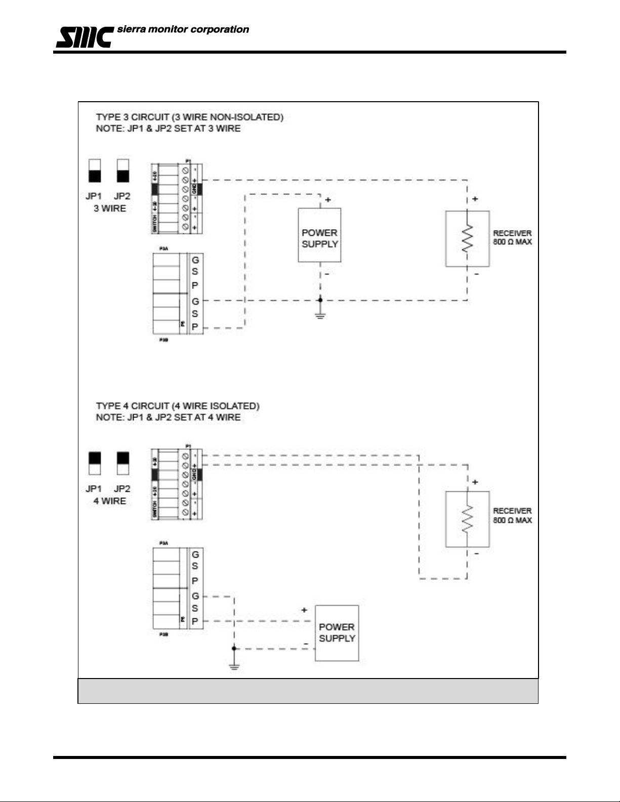
The standard configuration is set up for a 3-wire non-isolated connection. An optional 4-wire isolated
connection is also available and can be enabled by changing JP1 and JP2. (Figure 4.6)
1.4.4 REMOTE SENSOR (APPENDIX D)
The Remote Sensor option can be used to remotely mount some sensors up to 15’ from the transmitter
(refer to Appendix D for allowable distances).
1.4.5 HART CONNECTION (APPENDIX F)
A HART interface option is available. Refer to Appendix F for information.
Page: 2
Page 7

Model 5100-XX-IT Toxic Gas Sensor Module
1.4.6 REMOTE ALARM RESET
An input is available for connection of remote alarm reset. Figure 4-8 provides the wiring termination for
connecting the remote alarm reset. This only resets local alarms, not Sentry alarms.
1.4.7 OPTIONAL INTEGRAL RELAYS
The optional relays are integral to the gas sensor module and are rated as SPDT, 250VAC, 5 Amps* for
the High Alarm and Low Alarm relays and SPDT, 250 VAC, 0.25 Amp for the Trouble relay.
* HART option alarm relays are all SPDT, 250VAC, 2 Amp
If the gas sensor module is provided with the optional relays, it will include Terminal P4 on the interface
board (Figure 4-3 and 4-4). Relay output connections are on P4.
1.5 MECHANICAL
The sensor module is comprised of the following three primary components:
ENCLOSURE
Standard on the 5100-XX-IT is an explosion-proof, rain-tight cast aluminum electrical housing (Figure 1-3)
with three ¾” FNPT conduit hubs. The 5100-XX-IT-SS has a 316 Stainless Steel enclosure (Figure 1-2).
Both enclosure covers have a viewing window. The design of the enclosure allows 3-way mounting
choices as shown in figure 1-3.
TRANSMITTER ELECTRONICS
Electronic Assembly consisting of one printed circuit board assembly mounted under a cover plate,
plugged into one field termination board. Connectors for wiring for power, signal interface and alarm
relays are located on the bottom of the termination board.
SENSOR ASSEMBLY
The sensor assembly includes an explosion proof housing containing the gas sensor and a wiring harness
for connection to the transmitter. The sensor assembly threads into one hub of the enclosure. The
exposed end of the sensor assembly is threaded to allow connection of a rain-shield or calibration gas.
1.6 INTERCONNECT WIRING
Not supplied with the sensor module, but necessary to the installation and operation is the shield cable which
connects the module to its power source and controller. Before this wiring is installed it is important to read
and understand the control system installation instructions to determine wiring requirements and alternatives.
1.7 POWER REQUIREMENTS
The modules operate on DC power between 10 VDC and 30 VDC. Regulated DC power must be supplied
from a separate source or from an approved Sentry or IT controller.
Page: 3
Page 8
Model 5100-XX-IT Toxic Gas Sensor Module
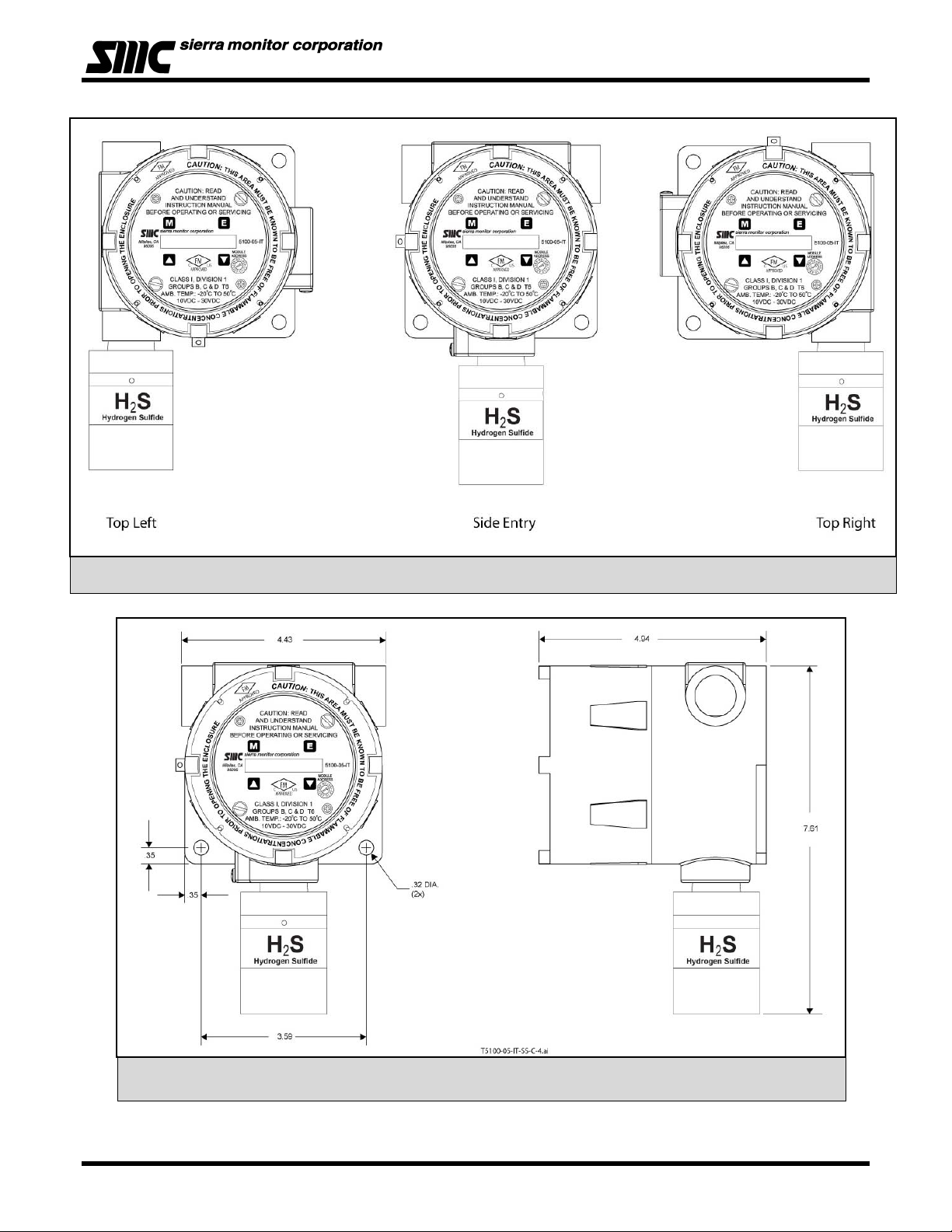
Figure 1 - 2: Model 5100-05-IT-S1 (and S2) Toxic Gas Sensor – Stainless Steel Enclosure, Dimensions
Figure 1 - 1: Model 5100-XX-IT Toxic Gas Sensor Module – Mounting Options
(Valid for all except 5100-25/26-IT – See Appendix G)
Page: 4
Page 9
Model 5100-XX-IT Toxic Gas Sensor Module
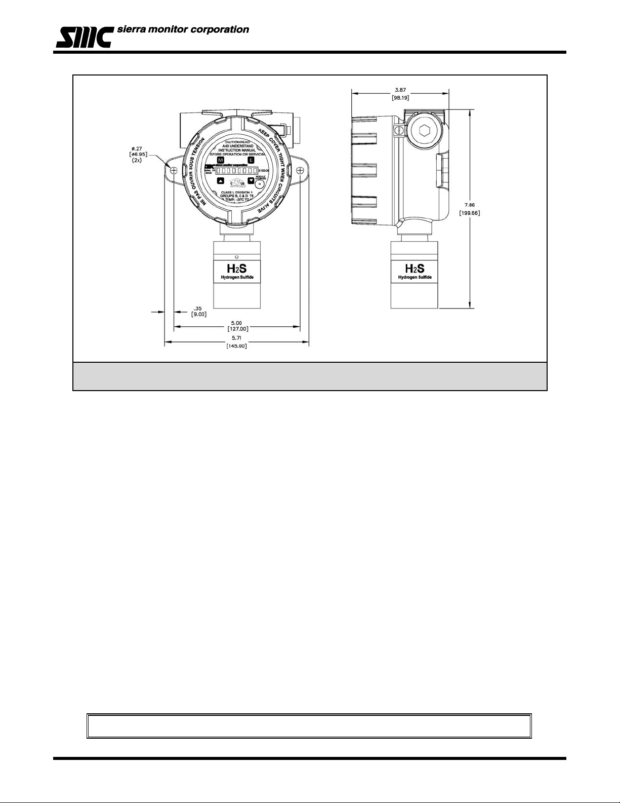
Figure 1 - 3: Model 5100-05-IT-A1 (and A2) Toxic Gas Sensor – Cast Aluminum Enclosure, Dimensions
(Valid for all except 5100-25/26-IT – See Appendix G)
Module installation must be such that it is mounted vertical with sensor pointing downward.
NOTE
Page: 5
Page 10

Model 5100-XX-IT Toxic Gas Sensor Module
2. CAUTIONS & WARNINGS
2.1 INTRODUCTION
Although the IT Transmitter Modules are designed and constructed for installation and operation in industrial
applications including “hostile” environments, caution should be taken to insure that the installation is made in
compliance with this instruction manual and that certain procedures and conditions are avoided. This chapter
discusses the necessary cautions. Read the entire chapter prior to installation of the equipment.
2.2 GAS SENSOR MODULES - GENERAL
Avoid installing sensor modules where they will be unnecessarily exposed to wind, dust, water (i.e. direct hose
down), shock, or vibration. Observe temperature range limitations.
Sensors may be adversely affected by prolonged exposure to certain materials. Loss of sensitivity, or
corrosion, may be gradual if such materials are present in low concentrations. These materials include:
Halides (compounds containing chlorine, fluorine, bromine, iodine), acid vapors, caustic liquids or mists.
Care has been taken by the manufacturer to ship modules in protective packaging to avoid contamination prior
to installation. It is recommended that the modules remain protected during installation and that the covering
be removed immediately prior to system start-up.
During normal use the O
, CO, H2S, and SO2 sensors are protected from dirt and oil contamination by a
2
sintered metal cover. If this cover becomes clogged, the response of the sensor will be reduced. Protect the
sensor from contamination by careful placement, or by use of rain shields and dust shields.
Sensor modules must not be painted. Paint may contain compounds which will contaminate the sensor. Paint
will cause clogging of the sintered metal cover and will cause difficulties during attachment of the calibration
head or other maintenance activity. It is recommended that the module be tagged
2.3 WIRING
"DO NOT PAINT".
The manufacturer recommends that extra caution be taken where the installation is near any sources of
electromagnetic or radio frequency interference. Precautions include:
• Avoid running sensor module cable close to high power cables, radio transmission lines, or cables
subject to pulses of high current.
• Avoid running cables near large electric motors or generators.
• When the sensor module is to be operated in analog (4-20mA output) mode shielded cable is required.
• When shielding is used, it is recommended that shields be grounded at the controller and nowhere
else.
• All splices must be via either a termination hardware system or soldered. Improperly spliced cable can
result in corrosion, resistance changes and system errors. The use of wire nuts and crimp-on
connectors is unacceptable.
Installation and wiring must be in accordance with the National Electrical Code.
Voltage AC conductors are not to be run in the same conduit as voltage DC
NOTE
conductors.
2.4 CALIBRATION FREQUENCY
The 5100-XX-IT calibration frequency is six months (180 days). However, prudent gas detector maintenance
practices normally suggest a simple recalibration following incidences of exposure to high levels of gas that
would lead to alarm activation within any system utilizing the output of the gas sensor module.
Page: 6
Page 11

Model 5100-XX-IT Toxic Gas Sensor Module
3. QUICK START
3.1 OVERVIEW
The gas sensor module has been supplied factory calibrated and ready for immediate installation and
operation. An installer familiar with installation and operation of gas detection products can use this section to
begin immediate use of the module.
3.2 WIRING
See section 4.2 to determine if 3-wire or 4-wire operation is necessary.
Provide two conductor twisted shielded wiring from the power supply/control device to the sensor module
location. Use wire that is 18 AWG or larger.
3.3 MODULE INSTALLATION
The sensor can be mounted in a variety of configurations supported by the conduit. See figure 1-3 to
determine which configuration is best for your specific application. The default configuration enables the
modules to be put in line with other modules with the sensor element below the transmitter. To change the
configuration simply remove the transmitter and rotate to the appropriate configuration and remount the
standoffs and transmitter.
The module is designed to be installed on a ¾” conduit. Two important warnings:
• The installation must meet any hazardous environment codes for electrical equipment.
• The sensor module enclosure mounting must be spaced far enough from any vertical surface
to allow removal and replacement of the sensor assembly which is threaded into one ¾”
conduit entry.
• Sensor housing must be oriented vertically pointing downward.
• If module is installed outdoors it is recommended that it be sheltered from direct sunlight.
3.4 TRANSMITTER INSTALLATION
To install the transmitter printed circuit assembly into the housing, carefully turn the faceplate so that the
printing is in the correct horizontal position for the mounting configuration and slide the assembly over the two
stand-offs in the enclosure.
Hand tighten the two captive panel thumb screws into the stand-offs. Replace the enclosure cover prior to
providing power to the transmitter
• If the transmitter is installed in a classified hazardous area, replace the threaded cover prior to
providing power.
3.5 START-UP & OPERATION
To begin operation of the sensor module activate the instrument loop with 14-30 VDC. Each time the sensor
module is powered up it will perform a warm-up for approximately 1.0 minutes (60 seconds). During this time
the display will read “Starting”. The loop output will be held at 4 mA.
NOTE: If the sensor is uncalibrated, the startup display will state “UNCALIB” instead of “STARTING”
NOTE: The 5100-06-IT, 5100-08-IT, 5100-25-IT, 5100-26-IT and 5100-88-IT require 300 seconds warm-up
period
After the warm-up period has expired, the display will indicate the gas concentration. Also, the instrument loop
will be released to output current in the range of 4 to 20 mA. The actual current is linear with the gas
concentration and depends on the selected range. For instance, when the range of 0 to 50 PPM has been
selected, a current of 4 mA corresponds to 0 PPM and a current of 20 mA corresponds to 50 PPM.
3.6 ZERO STABILIZATION
All electrochemical sensors require at least 30 minutes on power prior to calibration. This allows the electrode
potentials to equilibrate, resulting in a stable zero signal level.
Page: 7
Page 12
Model 5100-XX-IT Toxic Gas Sensor Module
4. INSTALLATION
4.1 SENSOR MODULE LOCATIONS
All modules are tagged to indicate the configuration including the sensor module number
Identify all components during unpacking and install using the factory configuration.
All IT modules are factory pre-configured and calibrated.
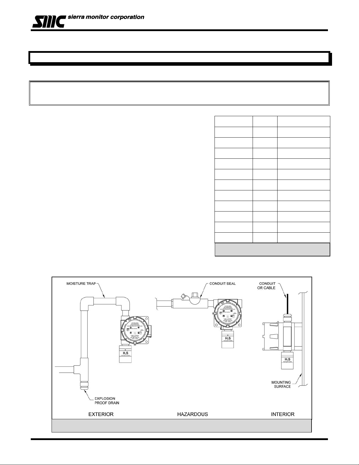
The gas sensor module utilizes a diffusion type sensor which
should be located close to either the expected source or
destination of the gas hazard. If the gas is heavier than air, the
sensor module should be installed within 24 inches of the ground
or floor. If it is lighter than air, move it above 6’.
After optimum locations are determined based on the above
recommendations, consideration should be given to placing the
sensor modules in locations which are accessible for calibration
service. Slight adjustments to the location of the sensor module
may have little impact on effectiveness but major effect on
accessibility.
• Modules should be placed close to the potential source
of gas.
• Modules should be placed in areas accessible for
calibration.
• Sensors should be pointed down and the conduit
should include an inverse trap to reduce moisture
(condensation) from accumulating in the electronics
enclosure.
• Remote calibration fitting (5360-00) should be used to
facilitate calibration gas delivery. Run polyurethane tubing (1/4” O.D. x 1/8” I.D.) from fitting to an
accessible location.
Figure 4 - 1: Typical Mounting Options
NOTE
Model Gas Gas Density
N/A Air 1.00
5100-04-IT CO 0.97
5100-05-IT H2S 1.19
5100-06-IT Cl2 2.49
5100-08-IT ClO2 3.09
5100-10-IT SO2 2.26
5100-12-IT NO2 2.12
5100-21-IT HCl 1.27
5100-25-IT NH3 0.60
5100-26-IT HF 1.86
5100-88-IT CO2 1.53
Table 4 - 1: Specific Graities
Page: 8
Page 13

Model 5100-XX-IT Toxic Gas Sensor Module
4.2 WIRING
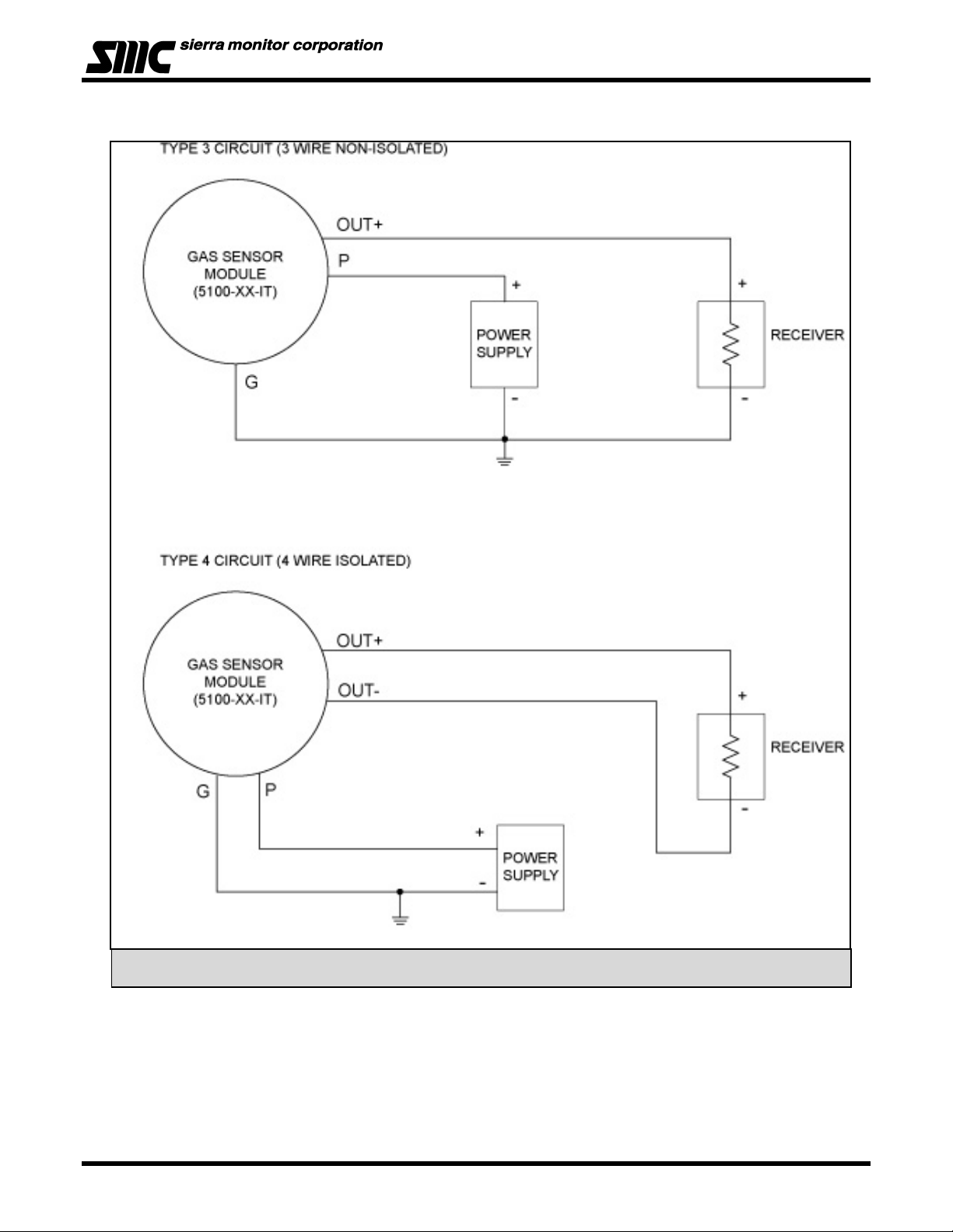
4.2.1 ANALOG 4-20 MA OPERATION (FIGURE 4-6)
For a 3-Wire non-isolated connection, set jumpers, located on the bottom of the transmitter board, to the
lower position as illustrated in Figure 4-6. Verify that both jumpers are in the position marked by 3-wire.
When using a 3-wire connection, a minimum of an 18 AWG, 3 conductor shielded cable must be used. A
cable shield must never be used as a conductor. Larger gauge wire is recommended with distances over
1000’. Connect wires as shown in figure 4-4.
For a 4-Wire isolated connection, set jumpers, located on the bottom of the transmitter board, to the upper
position as illustrated in Figure 4-4. Verify that both jumpers are in the position marked by 4-wire. When
using a 4-wire connection, a minimum of 2 each of an 18 AWG, 2 conductor twisted/shielded pair cable
must be used. A cable shield must never be used as a conductor. Larger gauge wire is recommended
with distances over 1000’. Connect wires as shown in figure 4-4.
4.2.2 MODBUS OPERATION USING RS-485 CONNECTION
Use a minimum of 18 AWG, 2 conductor for DC power connection. No shield required. In addition use a
minimum of 24 AWG, low capacitance, shielded data cable for RS485 half duplex communication. The
installation may be planned in a manner which provides up to 32 sensor modules on a single home run.
Standard default RS485 Setting are: 38,400 baud, 8 bits, 1 stop bit, no parity
TERMINATION RESISTOR JUMPERS:
Termination resistors are used in RS-485 wire runs to provide impedance matching. The IT series
modules use a 120 Ohm resistor for this function. The cable being used for this RS-485 connection must
have a minimum of 100 Ohm impedance with a maximum of 120 Ohms.
Installations where the cable length is under 100’, termination resistors may not be required. In
installations where the cable length is greater than 100’, it is recommended to place the termination
jumpers on the first device and last device on the RS-485 wire run. Termination jumpers must be removed
from all other modules connected between the first and last device. The first device in the RS-485
multiplexed bus is usually a gas controller or PLC. Factory term resistor setting is “not enabled.”
BIAS JUMPERS: (BIAS A, BIAS B)
Bias resistors are used to force RS-485 receiver outputs to a known (fail-safe) state, when the bus is idle.
Bias jumpers are always installed in pairs as the bias must be placed on both the TX A and TX B lines.
Sierra Monitor’s IT series of toxic gas sensors automatically apply the bias jumpers, and are factory
installed so that the bias is always enabled.
4.2.3 SENTRY OPERATION USING SMC SENTRY CONNECTION (FIGURE 4-7)
Use a minimum of 18 AWG, 3-conductor cable up to 2000’. The cable may or may not be shielded. We
recommend shielded cable in circumstances that there could be RF or EM interference present. Shield to
be terminated and grounded only at the Sentry controller. Shield must be cut and dressed at the module
end so that no part of it comes in contact with the conduit or ground.
Be sure to follow all local electric code and safety requirements when installing the 5100-XX-IT Gas Sensor Module
4.2.4 GENERAL
NOTE
Install conduit as required by local code or construction specifications. Provide for splice boxes where
multiple modules will be wired to a single run. Pull conductors of the correct gauge wire from the controller
to each splice box and from the respective splice box to each planned module location. See for proper
wire termination in the splice box. Twisted wire secured with wire nuts is not an acceptable splice.
The drain wire of shielded cable must NOT be used as one of the conductors.
Installation and wiring must be in accordance with the National Electrical Code. Temperature
rating of cable wire must be at least 75oC. If cable runs through higher temperature
environments, it must be specified for that environment.
NOTES
Page: 9
Page 14
Model 5100-XX-IT Toxic Gas Sensor Module
4.3 ENCLOSURE INSTALLATION
To protect the transmitter and sensor assembly they should be removed from the enclosure and preserved
until final installation and wiring termination.
Number
of
modules
1
2
3
4
Maximum length of wire run (feet)
500 1,000 2,000 3,000 5,000
18 18 16 16 14
18 18 14 12 xx
18 16 12 xx xx
16 14 12 xx xx
Table 4 - 2: Minimum Wire Gauges
Prior to installation and wiring:
1. Remove the transmitter from the module housing by:
• Unscrew the two captive panel screws on the faceplate.
• Lift the transmitter out of the enclosure.
• Unplug the sensor cable from transmitter connector P2.
• Remove the sensor assembly from the enclosure hub.
2. Install the module enclosure onto the end of the supply conduit and/or bolt into position as required.
When enclosure earth grounding is required for the installation a grounding lug is located in
the base of the enclosure. Install the earth ground under the green ground screw.
4.4 TRANSMITTER AND SENSOR INSTALLATION
NOTE
When all pre-wire is complete:
1. Install sensor assembly in the open hub on the module enclosure. The sensor assembly thread
must be fully seated into the hub and tightened to maintain explosion proof assembly.
2. Connect the wires which return to the controller to interface board connectors P1, P2, P3 and P4
according to Figure 4-3 and Table 4-4.
3. Connect the sensor assembly cable to top transmitter board connector P2.
4. Align the headers between the top transmitter board and the lower interface board and push
together.
5. Turn rotary switch to correct sensor address if required.
6. Carefully return the transmitter to the enclosure installing it over the two stand-off’s. Tighten the
retaining screws into the stand-offs.
7. Cycle power to accept module address change.
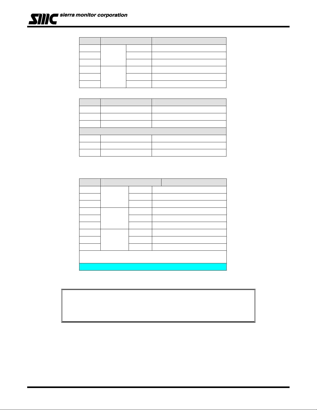
P1 PCB Label Function
1
2 IN - Digital Input SW -
3
4 IN - 4-20 mA Input -
5 GND Ground
6
7 OUT - 4-20 mA Output -
Switch
4-20
4-20
IN + Digital Input SW +
IN + 4-20 mA Input +
OUT + 4-20 mA Output +
Page: 10
Page 15
Model 5100-XX-IT Toxic Gas Sensor Module
P2 PCB Label Function
1
2 - RS 485 (-) (B)
3 S RS 485 shield (Isolated GND)
4
5 - RS 485 (-) (B)
6 S RS 485 shield (Isolated GND)
P3B PCB Label Function
1 P VDC Power
2 S Sentry Signal or Communication
3 G VDC Ground
P3A
4 P VDC Power
5 S Sentry Signal or Communication
6 G VDC Ground
P4 Connections are only available when the optional Relays are included
P4 PCB Label Function
1
2 COM Low Alarm Relay COM
3 N/O Low Alarm Relay NO
4
5 COM High Alarm Relay COM
6 N/O High Alarm Relay NO
7
8 COM Trouble Alarm Relay COM*
9 N/O Trouble Alarm Relay NO*
* Trouble relay is fail safe so it is energized for normal operation,
functions are labeled for normal operation.
RS 485
RS 485
WARNING
ALARM
TRBL
+ RS 485 (+) (A)
+ RS 485 (+) (A)
N/C Low Alarm Relay NC
N/C High Alarm Relay NC
N/C Trouble Alarm Relay NC *
8. Establish the module address according to section 4.5.
The starting delay period normally takes approximately 3 minutes but under some
circumstances can take longer.
For optimum performance, it is recommended that a calibration be performed after 24 hours of
NOTES
operation.
Page: 11
Page 16
Model 5100-XX-IT Toxic Gas Sensor Module
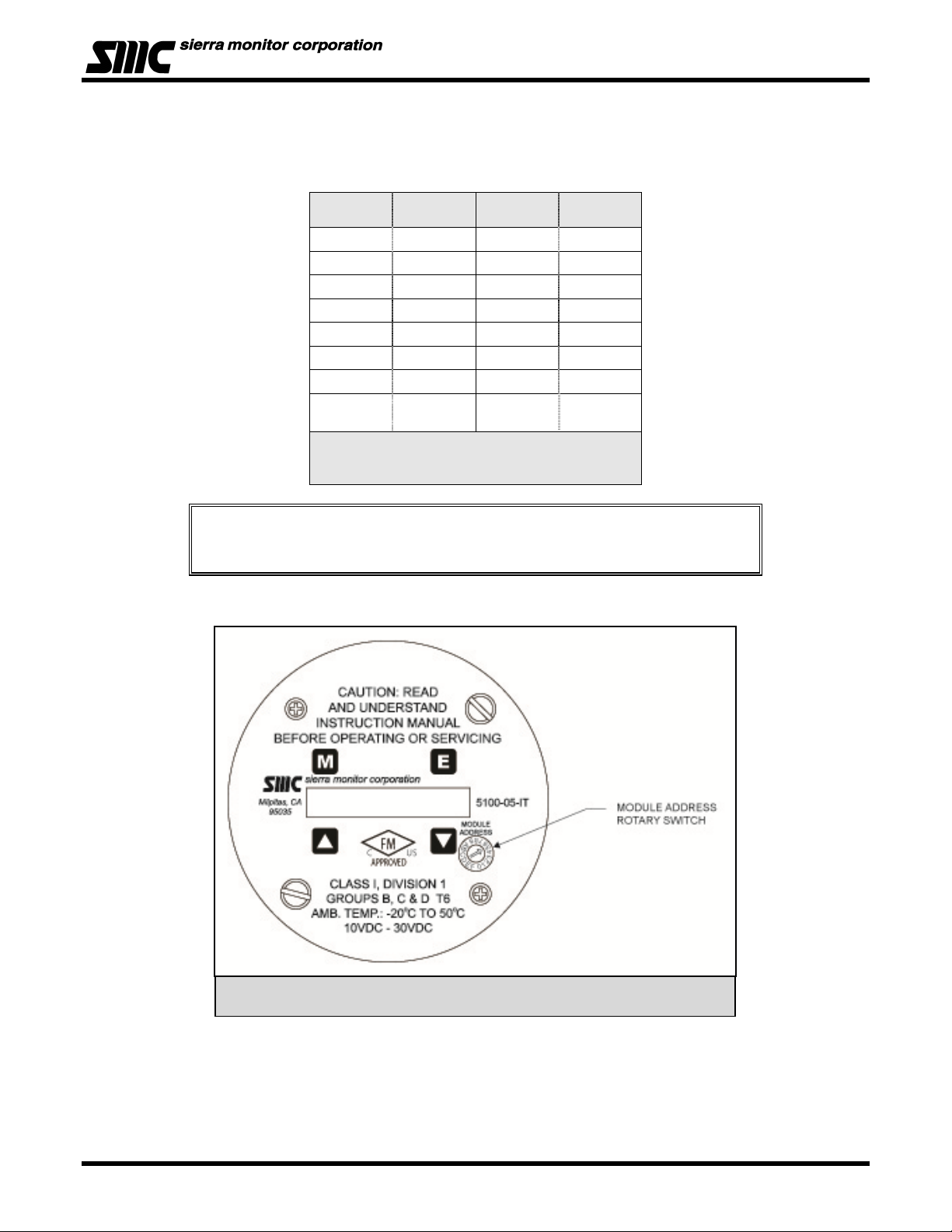
4.5 MODULE ADDRESS SWITCH
For digital interface applications the module address switch (or Modbus node) Figure 4-2 must be set per
Table 4-3:
POSITION ADDRESS POSITION ADDRESS
1 Sensor 1 9 Sensor 09
2 Sensor 2 A Sensor 10
3 Sensor 3 B Sensor 11
4 Sensor 4 C Sensor 12
5 Sensor 5 D Sensor 13
6 Sensor 6 E Sensor 14
7 Sensor 7 F Sensor 15
8 Sensor 8 0
Table 4 - 3: Sensor Module Address
Switch Positions
NOTES
For Sentry applications only sensor addresses 1-8 are allowed. If using Modbus output sensor
addresses 1-15 are available. Position 0 allows the Modbus Address to be set by software
menu, in the range 16-254.
Software
Menu
Figure 4 - 2: Transmitter Face Plate
Page: 12
Page 17
Model 5100-XX-IT Toxic Gas Sensor Module
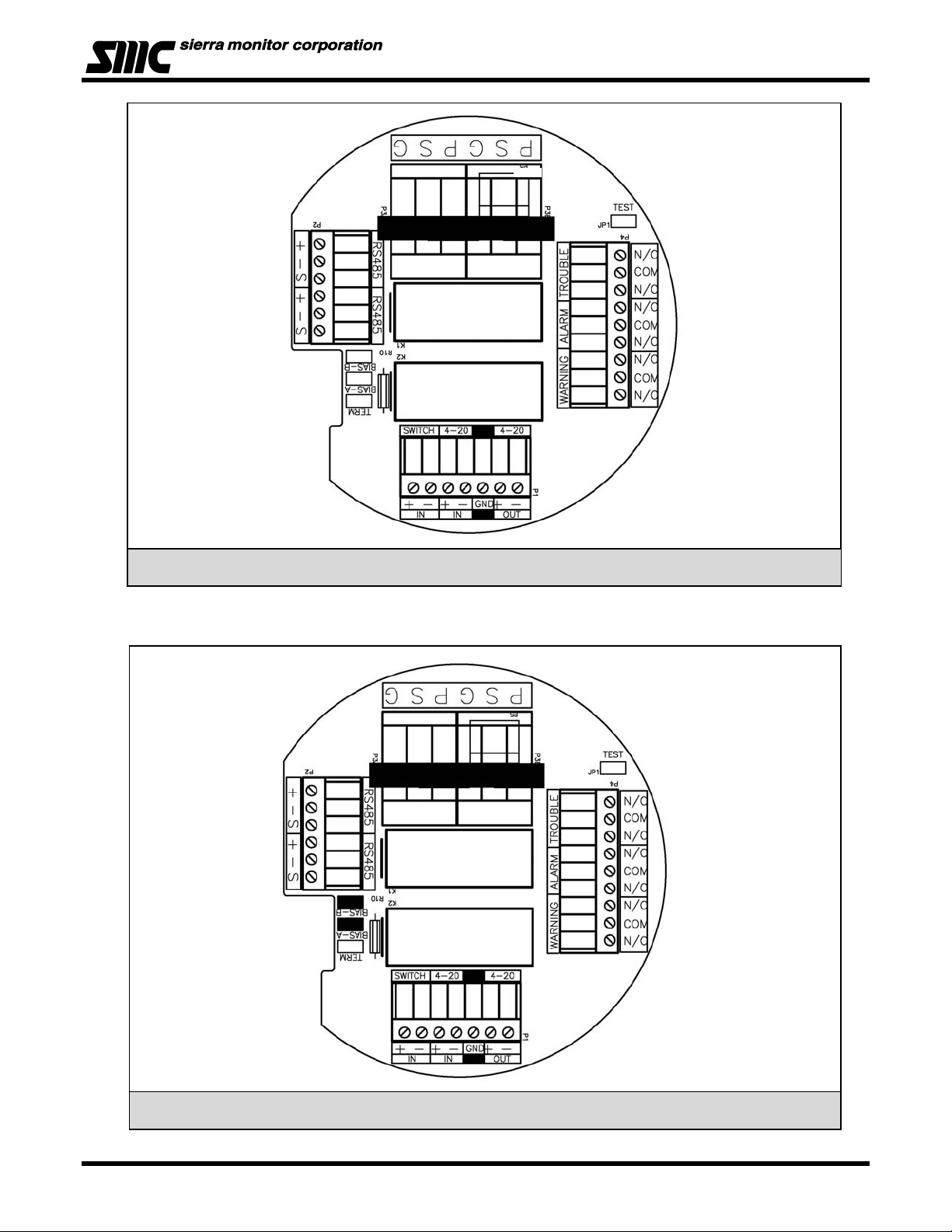
Figure 4 - 3: Interface Board Connectors
Figure 4 - 4: RS-485: Termination, BIAS Jumper
Page: 13
Page 18
Model 5100-XX-IT Toxic Gas Sensor Module
Figure 4 - 5: mA Circuit Types
Page: 14
Page 19
Model 5100-XX-IT Toxic Gas Sensor Module
Figure 4 - 6: 4-20 mA Circuit Type Connections for 5100-XX-IT
Page: 15
Page 20

Model 5100-XX-IT Toxic Gas Sensor Module
(Dry
)
Figure 4 - 7: Wiring Connections for Modbus and Sentry Interface
5100-XX-IT TO MODBUS DEVICE
5100-XX-IT TO SENTRY
contact only unpowered
Page: 16
Page 21

Model 5100-XX-IT Toxic Gas Sensor Module
(Dry
)
5100-XX-IT Remote Alarm Reset (Supervised)
5100-05-IT REMOTE ALARM RESET (SUPERVISED)
5100-XX-IT Remote Alarm Reset (Unsupervised)
contact only unpowered
P1
+
+
+
GND
- -
-
OUT
IN
IN
4.7K OHM (CUSTOMER SUPPLIED)
4-20
4-20
SWITCH
SWITCH IN
SWITCH IN
+
-
Figure 4 - 8: Wiring Connections for Remote Alarm Reset
Page: 17
Page 22

Model 5100-XX-IT Toxic Gas Sensor Module
5. OPERATION
5.1 INTRODUCTION
The Gas Sensor Module utilizes a visual menu system operated by means of a magnet. A magnetic tool
(5358-50) is supplied for this purpose. The menu system is used to configure alarm set-points, calibrate the
sensor module, and for maintenance procedures and alarms acknowledge.
5.2 DATA ENTRY KEYPAD
The module menu system is operated by means of directing the magnet stick toward each of four independent
hall-effect magnetic switches. Each switch functions as if it is a manually activated panel key. The keys are
located under the faceplate above and below the LED display and are labeled
in Figure 5-1.
M , E , and as shown
• Key
• Key
• Key
• Key
: MODE
ENTER
: UP (+)
: DOWN (-)
Figure 5 - 1: Face Plate with Operator Key Pad
Mode
Up
Enter
Down
Page: 18
Page 23

5.3 MAIN MENU
Function Display Description Reference
Key
M E
M E
ME
ME
M E
M E
M E
M E
M E
M E
M E
M E
Mode Switch [M]
Enter Switch [E]
Up Switch [▲] Previous Menu
Down Switch [▼] Next Menu
Mode ALMRSET: Mode Function - Alarm Reset
Mode ALMRSET: Mode Function - Alarm Reset
Mode CALIB:-- Mode Function - Calibrate Table 6-1
Mode SETUP:-- Mode Function - Set up alarms, relays, etc Table 5-3
Mode MAINT:-- Mode Function - Maintenance Table 5-4
Mode EXIT-?-- Exit Menu
Enter XXX PPM
Model 5100-XX-IT Toxic Gas Sensor Module
5100-XX First screen at power up: Model No.
VXX-XX-- Second screen at power up: Version No.
STARTING Third screen at start up: Starting Delay
XXX PPM Normal condition - default display
Banner: "Press [E] to reset alarm"
RESET Alarm Reset
XXX PPM Default Display
Apply Selected Mode (Exit)
XXX PPM Default Display
Table 5 - 1: Master Menu
(Once a minute the sensor displays module address)
Table 5-2 defines the key operational displays on the operator interface.
DISPLAY DESCRIPTION
STARTING
XXX PPM
LXXX PPM
HXXX PPM
Delay from loss of power at start-up
Concentration
Low Alarm (Warning)
High Alarm (Alarm)
Measures gas, concentration exceeds
CXXX PPM
100% of Full Scale
Calibration Mode
Acknowledged Function
Table 5 - 2: Operation Display Values
If display shows “Start” instead of “Starting”, the module must be calibrated before using it.
Page: 19
Page 24

Model 5100-XX-IT Toxic Gas Sensor Module
5.4 SET-UP
The sensor module set-points menu is used to initially set-up the alarm set points, relay actions, gas type and
range, 4-20 mA action or RS-485/Sentry address and baud rates, Digital Input and Warm-up time. Use the [▲]
or [▼] keys to select following menus and press [E] to select.
• Alarms: Use the [▲] or [▼] keys to select Low Alarm (Warning) or High Alarm (Alarm) menu. Key
[▲] will adjust the setpoint upwards and Key [▼] will adjust the value downwards. Once it reaches
the desired setpoint, Key [E] will accept it and ACK will appear.
Set-points can be configured using this menu up to the following values:
Model Warning Alarm
5100-03-IT 19.5% 16.5%
5100-04-IT 50 PPM 100 PPM
5100-05-IT 10 PPM 20 PPM
5100-06-IT 2.0 PPM 5.0 PPM
5100-08-IT 0.3 PPM 1.0 PPM
5100-10-IT 10 PPM 20 PPM
5100-12-IT 2 PPM 4 PPM
5100-21-IT 5 PPM 10 PPM
5100-25-IT 25 PPM 50 PPM
5100-26-IT 2.0 PPM 5.0 PPM
5100-88-IT 1000 PPM 2500 PPM
Factory Alarm Set Points
NOTE: To enable rising O2 Alarm set warning setpoint higher than 20.9%
• Relays: Use the [▲] or [▼] keys to select High Alarm (Alarm) or Low Alarm (Warning) relay menu
and press [E]. Use the [▲] or [▼] keys to select the correct alarm relay action for the application,
Latch, Sentry or Non-Latch. Selecting “Sentry” enables the Sentry controller to make all alarm
action decisions. * indicates the current selection.
• Range: Use the [▲] or [▼] keys to select Range menu and press [E]. When “Range” is selected
menu provides any choices of ranges available for the gas type selected. Use the [▲] or [▼] keys
to select the desired range. If the “User” range is selected, use the [▲] or [▼] keys to adjust the
high end of the range desired.
Factory Range Set-up
Model Range Other Available
5100-03-IT 5-25% 0-25%
5100-04-IT 0-500 PPM Variable
5100-05-IT 0-100 PPM Variable
5100-06-IT 0-10 PPM None
5100-08-IT 0-3 PPM None
5100-10-IT 0-100 PPM Variable
5100-12-IT 0-20 PPM None
5100-21-IT 0-20 PPM None
5100-25-IT 0-100 PPM Variable
5100-26-IT 0-10 PPM None
5100-88-IT 0-5000 PPM Variable
• 4-20mA: Use the [▲] or [▼] keys to select Calib or CalibOut menu and press [E]. The “Calib”
section of the menu allows the user to calibrate the 4 mA and 20 mA outputs. To calibrate the 4 mA
and 20 mA outputs it is necessary to have an amp meter connected to the 5100-XX-IT and upon
selecting the 4 mA output calibration then the [▲] or [▼] keys can be used to adjust the 4 mA
reading on the amp meter until it reads 4 mA. Similar steps can then be performed for the 20 mA
output. The CalibOut section allows the user to select the 4-20 mA output action desired during
calibration. * indicates the current selected value. Available selections include:
Page: 20
Page 25

Model 5100-XX-IT Toxic Gas Sensor Module
Track – the 4-20mA value tracks the calibration gas exposed to the gas sensor module
C2.50mA – the 4-20mA value is held at 2.50mA during calibration
C4.00mA – the 4-20mA value is held at 4.0mA during calibration.
• RS-485 - Use the [▲] or [▼] keys to select Address or Baud rate menu and press [E]. Note that the
5100-XX-IT has a rotary switch on the faceplate and it is used to select addresses 1-15. When
connected to Sentry the user can select 1-8 and when using Modbus RS-485 the user can select
addresses 1-15. For Modbus addresses above 15, set the rotary switch to 0 and then use the
“Address” menu to select any address between 16 and 254. The Baud rate menu allows the user
to select a baud rate of 38400, 19200, 9600, 4800 or 2400. * indicates current selection. (Sentry
default is 9600)
• DigInput – Use the [▲] or [▼] keys to select supervised or Non-supervised digital input and then
press [E] to change.
Key
Function Display Description Reference
--0%LE L- Default Display
M E
M E
M E
M E
ME
ME
ME
ME
Mode ALMRSET: Mode Function - Alarm Reset
Mode CALIB:-- Mode Function - Calibrate
Mode SETUP:--- Mode Function - Set Point Adjustments
Enter Alarms S.P. F unction - Alarm Adjust * A Below
Down Relays S.P. Function - Relays Adjust * B Below
Down Relays S.P. Function - Range Adjust * C Below
Down 4-20mA S.P. Function - 4-20 mA Adjust * D Below
Down Dig Input S.P. Function - RS-485/Sentry Output Adjust * E Below
High Alarm Set Point Adjustment Example
M E
M E
Enter H.Alarm S.P. Function - High Alarm Adjust *A
Enter HASP:60- High Alarm Set Point: current = 60
Use or keys to a djust to new set point
ME
Down (x5) HASP:55- High Alarm Set Point: new = 55
M E
Enter ACK Momentary Acknowledge of new Set Point
H.Alarm S.P. Function - H igh Alarm Adjust
Relays Set Po int Adjustment Example
M E
ME
M E
ME
ME
Enter H. Relay S.P. Funct ion - High Alarm Relay Adjust *B
Down L.Relay S.P. Function - Low Alarm Relay Adjust
Enter Latch
Down Sentry
Down *Sentry Low Alarm Relay set to Sentry
Use or keys to a djust to new relay action
(Latch, Sentry, NonLatc) * indicates current
NOTE: S entry indicates that Sentry controls relay
action and not the IT Sensor Module
Table 5 - 3: Set-Up Configuration
Page: 21
Page 26

Model 5100-XX-IT Toxic Gas Sensor Module
M E
M E
ME
ME
M E
Enter Range S.P. Function - Range Adjust *C
Enter
Down 10 PPM Press [E] if selecting 0-10 PPM range
Down USER Pres s [E] if selecting User adjustable range
Enter 100 PPM
*100 PPM
M E
M E
M E
M E
M E
ME
M E
Enter Calib S.P. Function - C alib Adjust *D
Enter Out: 4mA Use or keys to s elect 4 mA or 20mA
Enter 4mA Selects 4 mA
Enter ACK Momentary Acknowledge of new Set Point
Mode Calib S.P. Function - Calib Adjust
Down CalibOut S.P. F unction - Output during Calibration Adjust
Enter Track Use or keys to s elect Track, C2.50mA , C4.00mA
Gas Ra nge Adjustm ent Exam ple
Select [E] to select or or to selec t another and
press [E]
Select [E] to select or or to selec t another and
press [E]
4-20 mA Adjustment Example
Track = Output during calibration tracks the calibration gas,
C2.50mA = Outpu t during calibration is 2.50 m A, C4.00mA =
Output during calibration is 4.0 mA
M E
M E
M E
M E
M E
ME
M E
Enter *Track * = Current selection
RS-485 Adjustment Example
Enter Address S.P. Function - RS-485 Address Adjust *E
Enter Addr:016 Use or keys to e nter new address
Enter ACK New addres s selected
Enter Address S.P. Function - RS-485 Address Adjust
Down Baud S.P. Function - RS-485 Baud Rate Adjust
Enter *38400 Press [E] to select or [] or [] to select a nother
Table 5-3: Set-Up Configuration (Continued)
Page: 22
Page 27

Model 5100-XX-IT Toxic Gas Sensor Module
5.5 MAINTENANCE SUB-MENU
The maintenance menu enables the operator to view sensor and software versions. Sierra Monitor technical
support has access to other values as needed. The maintenance menu operation is described in Table 5-4.
Function Display Description Reference
Key
XXXPPM Default Display
M E
M E
M E
M E
M E
M E
Mode ALMRSET: Mode Function - Alarm Reset
Mode CALIB:-- Mode Function - Calibrate
Mode SETUP:- Mode Function - Set Point Adjustments
Mode MAINT:-- Mode Function - Maintenance
Enter
Enter CCC001 Module Custom Configuration Control number
3.XX Module Software Version Number
Table 5 - 4: Maintenance Menu
Page: 23
Page 28

Model 5100-XX-IT Toxic Gas Sensor Module
6. CALIBRATION
6.1 CALIBRATION FREQUENCY
The Gas Sensor Module has been calibrated in the factory prior to shipment. It is recommended that the user
calibrate before placing into service. The sensor module must be calibrated every 180 days at a minimum.
Periodic functional tests are advisable for critical applications and hostile environments. Oxygen sensors will
require more frequent adjustment.
The sensor module microprocessor software includes high-level self-checking algorithms which provide
continuous sensor diagnostic and self-adjustment. Users may select to increase calibration frequencies based
on low-drift experience during first two calibration periods.
6.2 CALIBRATION PREPARATION
Calibration of the sensor is accomplished by simple menu based steps and application of span gas.
If an error is made during any stage of the calibration process, hold the magnet stick at the [M] for 10 seconds. A scrolling display
will indicate “calibration aborted” and the sensor module will exit the calibration activity and return to normal operating mode. The
calibration procedure can then be restarted.
NOTE
Calibration must be performed only when the area is known to be clear of the gas of interest. When in doubt,
use a portable instrument to confirm that there is no background.
For compliance with Factory Mutual (FM) Approvals, the Sierra Monitor Model 1250-01, 1260 -05 and 1260-45
are the FM Approved calibration gas delivery devices. Use the Model 5358-01 Calibration Adapter delivery
fitting.
NOTE: Refer to Appendix G1 for information on use of permeation tube for 510025-IT and Appendix G2 for 5100-26-IT calibration.
6.3 CALIBRATION GAS DELIVERY METHODS
Calibration gas can be delivered to the sensors via the Model 5358-01:
Calibration Adapter (Figure 6-1) - used with portable calibrators.
CALIBRATION PROCEDURE
The Calibration Menu is described on Table 6-1:
The procedure requires that the menu “keys” be activated using the magnet
stick.
Each key press steps through the process of setting the zero value for clean air
and then setting the span value.
At each of these steps, apply calibration gas of the value corresponding to the
setting accepted on the sensor module display.
6.4 SENSOR EXPOSURE TO GAS
Calibration gas must be delivered to the sensor using the flow rate and duration
listed in below:
Figure 6 - 1: Model
5358-01 Calibration
Adapter
Model Calibration Gas Flow Period
5100-03-IT Air 300 cc of Zero Air or exposure to Ambient Air (3 minutes)
5100-04-IT Carbon Monoxide 300 cc/min Until Stable (minimum 3 minutes)
5100-05-IT Hydrogen Sulfide 300 cc/min Until Stable (minimum 3 minutes)
5100-06-IT Chlorine 300 cc/min Until Stable (minimum 3 minutes)
5100-08-IT* Chlorine 300 cc/min Until Stable (minimum 3 minutes)
5100-10-IT Sulfur Dioxide 300 cc/min Until Stable (minimum 3 minutes)
5100-12-IT Nitrogen Dioxide 300 cc/min Until Stable (minimum 3 minutes)
5100-21-IT Hydrogen Chloride 300 cc/min
5100-25-IT Ammonia See Appendix G1
5100-26-IT Hydrogen Fluoride See Appendix G2
5100-88-IT* Carbon Dioxide 300 cc/min Until Stable (minimum 3 minutes)
Page: 24
Page 29

* Note: Use 5PPM Cl2 to calibrate (set module to 1.5 PPM ClO2)
-
6.5 CALIBRATION SUB-MENU
Function Display Description Reference
Key
XXXPPM Default Display
M E
M E
M E
M E
M E
M E
Mode ALMRSET: Mode Function - Alarm Reset
Mode CALIB:--
Enter
Enter ACK Zero gas setting acknowledged
AL-0PPM -
10PPM-SP
Enter
C 4 PPM
C 4 PPM
CXXXPPM
Enter CAL-OK Calibr ation Passe d - now remove gas
WAIT-300
Mode Function - Calibrate
Banner: Apply zero gas, enter <E> when done (Not Applicable
for 5100-03-IT)
Operation: Confirm area clear of gas, or apply zero air to
sensor.
Banner: Select span, enter <E> to calibrate sensor
Banner: (5100-03-IT ) Specify Cal gas <E> when done
Banner: Apply span gas, then enter <E> to calibrat e gas sensor
Operation: Apply calbration gas.
Operation: As gas is applied the reading will increase - wait 3
minutes
Operation: Five minute time out before sensor is returned to
service.
Sub-Routines
ME
ME
M E
M E
Down 25PPM-SP
Down Adj-SPAN
Enter 25PPM-SP
Enter C 25PPM
M E
Enter
M E
Mode
10PPM-SP
C 25PPM
CAL-FAIL
WAIT-300
(Any)
XXXPPM
Banner: Select span, en ter <E> when done
Operation: Change Span Gas Value to 25PPM
Operation: User adjustable value
Operation: Ready for user adjustment
Banner: Apply 25PPM gas, then ent er <E> to calibrate gas
sens or
Operation: Apply calbration gas.
Operation: No calibration gas applied, or sensor did not respond
correctly.
Operation: Five minute time out before sensor is returned to
service.
Operation: Hold magnet over Mode Switch for ten senconds to
abort calibration
Banner: Cal ibrat ion Aborted
Default Display
Table 6 - 1: Calibration
Model 5100-XX-IT Toxic Gas Sensor Module
*
Sub A
Sub B
Sub A
Sub B
Sub C
Page: 25
Page 30

Model 5100-XX-IT Toxic Gas Sensor Module
5100-03-IT Oxygen Deficiency
It is recommended to use fresh Air as the calibration source for the Oxygen detector. If the area is
known to be safe with adequate air flow, you may use the surrounding Air to set the instrument span at
20.9 %. If the condition of the environment is unknown, then the customer may use a cylinder of Zero
Air as the span gas. Please note that the Oxygen concentration contained in Zero Air cylinders may
have anywhere from 20.0 to 21.0 % Oxygen as it is not a precise standard.
To calibrate the Oxygen sensor module, place the module into the calibration mode using the
magnetic wand. Press the Mode key until CALIB is displayed. Press Enter to begin. Select
Calibration value to be 20.9%. Press Enter to confirm. Apply span gas or use the surrounding Air
then press Enter to complete procedure.
5100-88-IT Carbon Dioxide
The CO
requirement to apply Zero gas. To calibrate the CO
mode using the magnetic wand. Press the Mode key until CALIB is displayed. Press Enter to begin.
Select calibration value, typical 2500 ppm, and press Enter to confirm. Apply span gas for at least 3
minutes or until stable. Press Enter to complete procedure.
transmitter also has a span only calibration adjustment. There is no zero adjustment or
2
detector, place the module into the calibration
2
The Analog output values to be transmitted during the calibration procedure are
selected in the maintenance configuration. Normal 20.9% value provides 17.3 mA.
NOTE
Page: 26
Page 31

Model 5100-XX-IT Toxic Gas Sensor Module
7. SERVICE
7.1 SENSOR MODULE CONFIGURATION
The gas sensor module is comprised of the following sub-assemblies (Figure 7-1):
5100-XX-IT Gas Sensor Module (See Appendix B)
XXXXXXX Aluminum Enclosure
SPL21823 316SS Enclosure
XXXXXXX Transmitter Assembly (See Appendix B)
XXXXXXX Sensor Assembly (See Appendix B)
5200-XX-IT Sensor (See Appendix B)
7.2 ENCLOSURE REPLACEMENT
The enclosure should be replaced if the cover threads or conduit threads have been damaged, or if the
enclosure has been damaged sufficiently that it no longer meets the required NEMA classification.
To replace the enclosure follow the transmitter and sensor assembly removal instructions, remove the
damaged enclosure from its conduit, install a new enclosure and continue the transmitter and sensor
assembly replacement instructions.
Figure 7 - 1: Module Components
Page: 27
Page 32

Model 5100-XX-IT Toxic Gas Sensor Module
7.3 TRANSMITTER REPLACEMENT
The transmitter assembly should be replaced when it is determined that it is unreliable, noisy or cannot be
adjusted for calibration. This may occur due to age, corrosion or failed components.
To replace the transmitter assembly:
a. Remove the cover of the main enclosure.
b. Unscrew the two thumb screws in the top of the cover plate, lift the assembly and rotate 90
wiring service loop.
c. Remove all wires from bond, marking them carefully so they can be correctly replaced.
d. Unplug the sensor connector from the transmitter.
e. Reverse the preceding steps to install the new transmitter.
f. Restore power and allow a minimum of 30 minutes for stabilization before re-calibration.
7.4 SENSOR REPLACEMENT
NOTE: Refer to Appendix H for information on sensor electrolyte replacement for 5100-25-IT and 5100-26-IT.
The gas sensor which is located inside the sensor assembly housing can be replaced without replacement of
the housing. The gas sensor needs replacement when:
The “CAL-FAIL” message appears after calibration.
The sensor output signal is noisy, causing erroneous gas level readings.
The “Sensor Failure” message displays.
o
to relieve the
To replace the sensor:
a. Confirm that system power has been removed.
b. Remove the gas sensor module enclosure cover.
c. Unscrew the two thumb screws in the top of the faceplate, lift the transmitter assembly and rotate 90
relieve the wiring service loop.
d. Unplug the sensor connector from the transmitter.
e. Unscrew the old sensor assembly from the enclosure conduit hub. Remove the sensor assembly with its
harness.
f. Unscrew sensor housing cover from the sensor.
g. Carefully pull the old sensor straight up from the socket.
h. Press the new sensor into the socket.
i. Reverse the preceding steps to install the sensor assembly.
j. Allow the new sensor to stabilize for a minimum of 60 minutes and then calibrate using the procedure in
Section 6.
7.5 INSTALLATION INSPECTION
Prior to system start-up or trouble shooting, the entire system should be visually inspected. The following are
guidelines for that inspection:
7.5.1 CONTROLLER INSTALLATION
• Controller installed in conformance to instruction manual recommendations.
• AC power is correctly grounded.
• Hot AC and relay connections have safety covers installed.
7.5.2 CABLING INSTALLATION
o
to
• All splices are soldered or via terminal block.
• Cabling is away from sources of electrical noise or RFI where possible.
7.5.3 SENSOR MODULE INSTALLATION
• Module installation in conformance with this manual.
• Modules accessible for calibration.
• Wiring terminations clean and correct.
Page: 28
Page 33

Model 5100-XX-IT Toxic Gas Sensor Module
7.5.4 MOISTURE TRAPS AND RAINSHIELDS
• Conduit seals and drains installed to avoid moisture build up in electronics enclosure. Water accumulation
in sensor module enclosures is a major cause of damage and system failures - take precautions to seal
electrical conduits and provide moisture traps and drains to avoid water damage.
• Rain-shields installed where applicable.
7.5.5 STANDARD VOLTAGES
• Regulated DC voltage to be applied to the sensor module must be between 10 VDC and 30 VDC.
7.6 INSPECTION AND TROUBLESHOOTING GUIDE
The inspection and troubleshooting guide can be used to step through the system start-up and to determine
the corrective action if a fault occurs.
7.6.1 IF IR MODULE DOES NOT RESPOND TO GAS
1. Repeat calibration procedure.
2. Remove the gas and wait for the timer to completely count down.
3. Apply calibration gas and verify that the sensor sees calibration gas after calibration.
4. If the sensor still does not see gas, power cycle the unit and repeat calibration.
7.6.2 IF THE MODULE DISPLAYS “STARTING” FOR MORE THAN 1 HOUR
1. Make sure the sensor is placed in an ambient room temperature environment.
2. Power cycle the sensor.
3. Ensure that the sensor is not exposed to gas of interest during warm-up.
7.6.3 IF THE MODULE DOES NOT DISPLAY THE CORRECT %PPM
1. Power cycle the unit.
2. Recalibrate the sensor.
7.6.4 IF THE DISPLAY SHOWS ‘F’ – SENSOR MISSING OR BAD SENSOR
1. Power down the unit.
2. Open the enclosure and unplug the sensor assembly from the transmitter board.
3. Plug the sensor back into the transmitter board carefully and ensure a secure fit.
4. Check all other connections.
5. Power up the unit.
7.6.5 IF THE MODULE SHOW S “***CALIBRATION REQUIRED***”
1. Calibrate the module.
7.6.6 IF THE DISPLAY SHOWS ‘H’ (OR L) THEN THE LOCAL HIGH OR LOW ALARM IS ACTIVE
7.6.7 IF THE DISPLAY SHOWS “M” – NOT CALIBRATED
1. Calibrate the module.
7.6.8 IF THE DISPLAY SHOWS “C” – CALIBRATION MODE
1. Complete calibration and exit to operating mode.
7.6.9 IF THE DISPLAY SHOWS “S” – SENTRY CONNECTION
1. Check connections with Sentry Controller
7.6.10 DIAGNOSTIC LEDS
LED 1 = 1 Hz Heartbeat normal, 2 Hz Panic Error
2 = Computation process
3 = 1 Hz Heartbeat normal
4 = HART or Sentry comms activity
Page: 29
Page 34

Model 5100-XX-IT Toxic Gas Sensor Module
8. APPENDICES
8.1 APPENDIX A: SPECIFICATIONS
Sensor:
Type: Electrochemical
5100-03-IT O2
5100-04-IT CO
5100-05-IT H2S
5100-06-IT Cl2
5100-08-IT ClO2
5100-10-IT SO2
5100-12-IT NO2
5100-21-IT HCl
5100-25-IT NH3
5100-26-IT HF
5100-88-IT CO2
(1) Optional ranges available
(2) Response time to 90% full signal value for applied concentration
(3) Sensor life typical for use at standard temperature and pressure with occasional exposure to gas of interest
(4) Diffusion via membrane. Requires electrolyte
(5) Max range, zero drift, linearity, resolution, and sensor life, have not been verified by FM Approvals.
(6) Or +/- 10% of reading
(7) Electrolyte recharge only
Standard
Range
5-25% Vol 0-25% Vol +/- 0.1% +/- 0.2% +/- 0.2% +/- 0.1% <10 sec. +/- 0.2% 2 years
0-500 PPM 1200 PPM +/- 1 PPM +/- 1 PPM +/- 1 PPM 0.5 PPM <35 sec. +/- 1 PPM 2 years
(5)
0-100 PPM 100 PPM +/- 0.5 PPM +/- 1 PPM +/- 1 PPM 0.1 PPM <35 sec. +/- 3 PPM
0-10.0 PPM 10.0 PPM +/- 0.5 PPM +/- 0.5 PPM +/- 0.5 PPM 0.1 PPM <60 sec. +/- 0.5 PPM 2 years
0-3.0 PPM 3.0 PPM +/- 0.5 PPM +/- 0.5 PPM +/- 0.5 PPM 0.1 PPM <60 sec. +/- 0.5 PPM 2 years
0-100 PPM 100 PPM +/- 0.5 PPM +/- 1 PPM +/- 1 PPM 0.5 PPM <20 sec. +/- 0.5 PPM 2 years
0-20 PPM 20.0 PPM +/- 0.5 PPM +/- 0.5 PPM +/- 0.5 PPM 0.2 PPM <35 sec. +/- 0.5 PPM 2 years
0-20 PPM 20.0 PPM +/- 0.5 PPM +/- 0.5 PPM +/- 0.5 PPM 0.2 PPM <35 sec. +/- 0.5 PPM 2 years
(4)
0-100 PPM 100 PPM +/- 1.0 PPM +/- 1.0 PPM +/- 1.0 PPM +/- 1 PPM <30 sec. +/- 1 PPM 1 year
(4)
0-10 PPM 10 PPM -- -- -- 0.5 PPM <30 sec. +/- 1 PPM 1 year
0-5000 PPM
Optional
(1)
Max Range
5000 PPM +/- 1.0 PPM +/- 1.0 PPM +/- 1.0 PPM +/- 1 PPM <20 sec. +/- 2% 2 years
Zero Drift Repeatability Linearity Resolution
Response
Time
Output:
Display: Fixed and Scrolling LED
Relays Option: 5 Amp, High Alarm, Low Alarm, .25 Amp Trouble all SPDT
Analog Output: Analog 4-20 mA (Trouble 1.5mA, Calibration 2.5mA)
Loop Resistance 800 ohm
Signal Output: Sentry digital bus
Analog 4-20 mA
3-wire Non-Isolated
4-wire Isolated
Serial RS-485 Modbus RTU
HART
Input:
Remote Alarm Reset: Normally open digital input
Power:
Power consumption: 2 watts (3 watts for 5100-88-IT)
Input voltage: 24 VDC nominal: 10-30VDC
Accuracy
(2)
Sensor
Life
(6)
2 years
(3)
(7)
(7)
Page: 30
Page 35

Model 5100-XX-IT Toxic Gas Sensor Module
Operating Range:
5100-03-IT O2
5100-04-IT CO
5100-05-IT H2S (5)
5100-06-IT Cl2
5100-08-IT ClO2
5100-10-IT SO2
5100-12-IT NO2
5100-21-IT HCl
5100-25-IT NH3 (4)
5100-26-IT HF (4)
5100-88-IT CO2
Enclosure:
Material - Aluminum: Polyester powder-coated, sand-cast, copper-free aluminum
Material - Stainless Steel: 316 Stainless Steel
Dimensions: (HxWxD) (differs for 5100-25-IT & 5100-26-IT)
(A1 & A2) 7.9 x 5.7 x 3.9 in. (20.1 x 14.5 x 9.9 cm)
(S1 & S2) 7.6 x 4.4 x 4.9 in. (19.3 x 11.2 x 12.4 cm)
Weight: (A1 & A2) 3.4 lb. (1.5 Kg)
(S1 & S2) 7.2 lb. (3.3 Kg)
Housing: NEMA 4X, NEMA 7
Hazardous Area Approval: Explosion proof, Class 1, Div. I, Groups B, C, D
Group IIB + H2 IP66, IP65, NEMA 4X
Electrical Approvals:
Factory Mutual (FM): Class 1, Div. I, Groups B, C, D
FM Standards 3600, 3615, 3810
UL: UL Standard 508A
ATEX (5100-XX-IT): II 2 G Ex d IIB+H2 T6 Gb Ta = -20
Performance Approvals:
FM Performance Approval: FM Performance Approval (5100-05-IT) (Appendix I)
SIL-2 Certified (5100-04-IT, 5100-05-IT, 5100-06-IT)
CE Mark (5100-05-IT)
ABS (5100-05-IT)
CQST
Remote Sensor Option (Appendix D):
Distance between sensor and transmitter:
5100-03-IT 10 feet 5100-06-IT 10 feet
5100-04-IT 15 feet 5100-08-IT 10 feet
5100-05-IT 15 feet 5100-10-IT 15 feet
Warranty:
Limited Warranty: 2 years
Specifications subject to change without notice
Ambient Temp (oF) Ambient Temp (oC) Relative Humidity
5 to 122
- 4 to 122
- 40 to 122
- 4 to 122
- 4 to 122
- 4 to 122
- 4 to 122
- 4 to 122
+14 to 113
+14 to 113
- 4 to 140
o
F -15 to 50 oC 15 – 90%
o
F -20 to 50 oC 15 – 90%
o
F -40 to 50 oC 15 – 90%
o
F -20 to 50 oC 15 – 90%
o
F -20 to 50 oC 15 – 90%
o
F -20 to 50 oC 15 – 90%
o
F -20 to 50 oC 15 – 90%
o
F -20 to 50 oC 15 – 90%
o
F -10 to 45 oC 20 – 95%
o
F -10 to 45 oC 20 – 95%
o
F -20 to 60 oC 15 – 90%
o
C to +50oC
Page: 31
Page 36

Cross Sensitivity Data:
5100-04-IT Carbon Monoxide
Gas Conc. Response
HS 15 PPM ~38 PPM
SO
5 PPM ~3 PPM
2
NO 35 PPM ~10 PPM
NO
5 PPM ~-3 PPM
2
H
100 PPM <60 PPM
2
C
100 PPM <100 PPM
2H4
HCN 10 PPM ~5 PPM
HCl 5 PPM 0 PPM
5100-05-IT Hydrogen Sulfide
Gas Conc. Response
CO 400 PPM <.1 PPM
SO
20 PPM <10 PPM
2
NO 50 PPM <3 PPM
NO
10 PPM <-30 PPM
2
Cl
10 PPM <-25 PPM
2
H
400 PPM 1 PPM
2
C
NH
400 PPM <0.1 PPM
2H4
20 PPM <0.1 PPM
3
5100-06-IT Chlorine &
5100-08-IT Chlorine Dioxide
Gas Conc. Response
CO 300 PPM 0 PPM
H
S 15 PPM 0 to -3.38 PPM
2
SO
5 PPM -0.05 PPM
2
NO 35 PPM 0 PPM
NO
5 PPM ~5 PPM
2
H
100 PPM 0 PPM
2
C
100 PPM 0 PPM
2H4
HCN 10 PPM 0 PPM
HCl 5 PPM 0 PPM
ClO
3 PPM 10 PPM
2
5100-10-IT Sulfur Dioxide
Gas Conc. Response
H
S 15 PPM 0 PPM
2
NO 35 PPM -7 to 0 PPM
NO
5 PPM -5 PPM
2
Cl
5 PPM -1.5 to 0 PPM
2
NO
5 PPM ~5 PPM
2
H
100 PPM 0 PPM
2
HCN 10 PPM <5 PPM
HCl 5 PPM 0 PPM
C
100 PPM 0 PPM
2H4
Model 5100-XX-IT Toxic Gas Sensor Module
5100-12-IT Nitrogen Dioxide
Gas Conc. Response
CO 300 PPM 0 PPM
H
S 15 PPM -1.5 to 0 PPM
2
SO
5 PPM -0.05 to 0 PPM
2
NO 35 PPM 0 PPM
Cl
1 PPM ~1 PPM
2
H
100 PPM 0 PPM
2
HCN 10 PPM 0 PPM
HCl 5 PPM 0 PPM
C
100 PPM 0 PPM
2H4
5100-21-IT Hydrogen Chloride
Gas Conc. Response
CO 300 PPM <3 PPM
H
S 15 PPM 27 to 45 PPM
2
SO
5 PPM 1.5 to 3.5 PPM
2
NO 35 PPM 0 PPM
NO
5 PPM 0.5 to 1 PPM
2
Cl
1 PPM -0.05 to 0.1 PPM
2
H
100 PPM <0.5 PPM
2
HCN 10 PPM <0.3 PPM
5100-25-IT Ammonia
Gas Conc. Response
CO 1000 PPM 0 PPM
SO
15 PPM >40 PPM
2
NO 100 PPM 0 PPM
NO
60 PPM 0 PPM
2
H
4% 0 PPM
2
CH
4% 0 PPM
4
HCN 10 PPM 75 PPM
H
S 3 PPM 75 PPM
2
5100-26-IT Hydrogen Fluoride
Gas Conc. Response
Cl
5 PPM 8 PPM
2
HCl 5 PPM 9 PPM
NH
75 PPM 0 PPM
3
SiH
15 PPM 0 PPM
4
CO 1000 PPM 0 PPM
SO
5 PPM 9 PPM
2
NO 100 PPM 0 PPM
NO
15 PPM 2 PPM
2
H
4% 0 PPM
2
H
S 30 PPM 0 PPM
2
Page: 32
Page 37

Model 5100-XX-IT Toxic Gas Sensor Module
8.2 APPENDIX B: MODEL NUMBERS & PARTS LIST
Sensor Module
Model Gas Enclosure Output Protection Option ATEX
5100 - XX - IT - XX - XX - XX - X - X - X
5100 Series - 03 = O
- 04 = CO
- 05 = H
- 06 = Cl
- 08 = ClO
- 10 = SO
- 12 = NO
- 21 = HCl
- 25 = NH
- 26 = HF
- 88 = CO
Options 5311-00 Rainshield
- IT Series - A1 = AL ¾” NPT - 01 = No Relays (std) - 00 = Std - 0 = Standard - 0 = None - 0 = Standard
2
S
2
2
2
2
2
- A2 = AL M20 x 1.5 - 02 = Relays Option
- S1 = SS ¾” NPT - 05 = HART Option
- S2 = SS M20 x 1.5
3
2
5311-02 Rainshield with calibration port
Calibration Items 1250-01 Gas Sensor Calibration Kit, Type A (CO, H
1250-02 Gas Sensor Calibration Kit, Type B (SO2, NO2)
1250-03 Gas Sensor Calibration Kit, Type C (Cl
1260-00 Gas Cylinder, Air, (Type A), 105 liters
1260-04 Gas Cylinder, CO 100 PPM, (Type A) 57 liters
1260-05 Gas Cylinder, H
1260-06 Gas Cylinder, Cl
1260-10 Gas Cylinder, SO
1260-12 Gas Cylinder, NO
1260-13 Gas Cylinder, CO, 1000 PPM, (Type A), 105 liters
5360-00 Calibrator Head Standard
1256-01 Regulator Type A Calibrator
1256-02 Regulator Type B Calibrator
1265-03 Regulator Type C Calibrator
5358-01 Calibration Adapter - Direct, Standard
5358-51 Calibration/Configuration Magnetic Tool, 4501-XX
9210-00 Calibrator, Permeation Tube
9211-09 Permeation Tube, Ammonia, NH
SPX27057 Kit, Sensor Recharge, for 5100-25-IT
SPX27061 Kit, Sensor Recharge, for 5100-26-IT
See Appendix D for 5100-25-IT and 5100-26-IT
Spare Parts 5200-03-IT Sensor, for 5100-03-IT
5200-04-IT Sensor, for 5100-04-IT
5200-05-IT Sensor, for 5100-05-IT
5200-06-IT Sensor, for 5100-06-IT / 5100-08-IT
5200-10-IT Sensor, for 5100-10-IT
5200-12-IT Sensor, for 5100-12-IT
5200-21-IT Sensor, for 5100-21-IT
SPL21834 Sensor Assembly, Aluminum, for 5100-03-IT - Oxygen
SPL21832 Sensor Assembly, Aluminum, for 5100-04-IT - CO
SPL21830 Sensor Assembly, Aluminum, for 5100-05-IT - H
SPL21833 Sensor Assembly, Aluminum, for 5100-06-IT / 5100-08-IT - Cl
SPL21844 Sensor Assembly, Aluminum, for 5100-10-IT - SO2
SPL21845 Sensor Assembly, Aluminum, for 5100-12-IT – NO
SPM21878 Sensor Assembly, Plastic, for 5100-26-IT
SPM27082 Sensor Assembly, 316SS, for 5100-03-IT - Oxygen
SPM27083 Sensor Assembly, 316SS, for 5100-04-IT - CO
SPM27074 Sensor Assembly, 316SS, for 5100-05-IT - H
SPM27084 Sensor Assembly, 316SS, for 5100-06-IT / 5100-08-IT - Cl
SPM27087 Sensor Assembly, 316SS, for 5100-10-IT - SO
SPM27088 Sensor Assembly, 316SS, for 5100-12-IT - NO
SPL21824 Transmitter
SPL21810 Enclosure, Transmitter, Aluminum
SPL21823 Enclosure Transmitter, 316SS
SPL21825 Interface Board without Relay
SPL21829 Interface Board with Relay
Relay/Connection Sensor Remote
- 1 = Conformal - 1 = Remote - C = ATEX/IECEx
Sensor Sensor (5100-05 only)
S, Air)
2
)
2
S in N2, 25 PPM, (Type A) 57 liters
2
, 5 PPM, (Type C) 104 liters
2
, 50 PPM, (Type B) 74 liters
2
, 10 PPM, (Type B) 74 liters
2
3
S
2
2
S
2
2
2
& ClO
2
& ClO2
2
2
Page: 33
Page 38

Model 5100-XX-IT Toxic Gas Sensor Module
8.3 APPENDIX C: LIMITED WARRANTY
SIERRA MONITOR CORPORATION warrants its products to be free from defects in workmanship or material
under normal use and service for two years after date of shipment. SMC will repair or replace without charge
any equipment found to be defective during the warranty period. Final determination of the nature and
responsibility for defective or damaged equipment will be made by SMC personnel.
All warranties hereunder are contingent upon proper use in the application for which the product was intended
and do not cover products which have been modified or repaired without SMC approval or which have been
subjected to accident, improper maintenance, installation or application, or on which original identification
marks have been removed or altered. This Limited Warranty also will not apply to interconnecting cables or
wires, consumables (i.e. calibration gases, batteries, sensors), nor to any damage resulting from battery
leakage.
In all cases SMC’s responsibility and liability under this warranty shall be limited to the cost of the equipment.
The purchaser must obtain shipping instructions for the prepaid return of any item under this warranty
provision and compliance with such instruction shall be a condition of this warranty.
Except for the express warranty stated above, SMC disclaims all warranties with regard to the products sold
hereunder including all implied warranties of merchantability and fitness and the express warranties stated
herein are in lieu of all obligations or liabilities on the part of SMC for damages including, but not limited to,
consequential damages arising out of/or in connection with the use or performance of the product.
Page: 34
Page 39

Model 5100-XX-IT Toxic Gas Sensor Module
8.4 APPENDIX D: REMOTE SENSOR DRAWING
Figure 8 - 1: Remote Sensor Drawing
Drawing using Aluminum enclosure available from Sierra Monitor.
NOTE
Page: 35
Page 40

Model 5100-XX-IT Toxic Gas Sensor Module
8.5 APPENDIX E: MODBUS MEMORY MAP
Register Description Read/ Comments
40001 Con cent ratio n R Ga s conc entra tion mul tipl ie d by Ga s Scal e (e .g. 209 = 20.9%)
40002 Tem pera ture R Tem pera ture i n de gre es Ce lci us sca led by a f actor o f 10
40003 Al arm Re lay R/W
40004 Warn ing R elay R/ W Boo lea n in dicat ing t he Wa rnin g rel ay st atus ( 0 = No A larm , 1 - War ning Ala rm). C le aring bit w ill reset alarm.
40005 Warn ing S etpo int R/W Warni ng A larm s et p oint , use d fo r acti vati ng Low Ala rm mul tip lie d by Gas Sca le
40006 Al arm Se tpoi nt R/ W Al arm se t poi nt, used for a ctiv ating High Alar m mul tip lie d by G as Scal e
40007 CCC detail R e.g. 0001, 0007, et c
40008 Sof twar e Rev isi on U R e .g. 201 d enot es v ersi on 2. 01
40009 Sof twar e Rev isi on L R e .g. vers ion a A is deno ted by 0x6141
40010 Modb us Map R evi sio n R e.g . ve rsio n 2 is deno ted a s v2 = 0x 7602
40011 Trou ble Bits R 0 = no t roub le
40012 Trou ble R 1 fo r any t roubl e, 0 = no tro ubl e
40013 Al arm Im medi ate R Lik e 40003, b ut ne ver latch ed
40014 Warn ing I mmed iate R Li ke 40004, but n eve r lat ched
40015 Se rial Numb er U R S eri al N umbe r - 24 bi ts ( pres entl y se t to R andom ID)
40016 Se rial Numbe r L R
40017 Run time U R In s econ ds
40018 Run time L R I n se conds
40019 Gas ( MAX) valu e R Ga s conc entra tion mul tipl ie d by Ga s Scal e
40020 Mode l R Read as 51028 f or IR, 51002 for C at Bea d, 51005 f or TOX IC H2S e tc.
40021 Rang e R W
40022 Uni ts RW 1 = %LEL, 2 = %V OL
40023 Modu le S tatus R
40024 Gas S cale R V alue lik e 1, 10 o r 100
40025 Cal Conce ntra tion lev el R/ W Gas c once ntrati on v alue use d dur ing c alib rati on, m ulti pli ed b y Gas S cale
40026 Cal ibra tion due , in d ays R Ge ts re set t o 365 / 180 i f cal succe ssfu l, L ess t hen 0 = cali brati on du e
40027 Cal ibra tion Coun t R Cou nter incre men ts i f cal succe ssfu l (0 = not cal ibr ated )
40028 Dis pla y Gas Ou tput R Gas val ue se en o n di spla y (i .e. usef ul d urin g cal ibrat ion )
40029 Gas ( MIN) valu e R Min imum gas v alue mul tipl ie d by Ga s Scal e
40030 Al arm Ti me U R In seco nds
40031 Al arm Ti me L R
40032 Warn ing Ti me U R I n se conds
40033 Warn ing Ti me L R
40034 Trou ble Time U R I n se conds
40035 Trou ble Time L R
40036 Max Ga s Tim e U R In seco nds
40037 Max Ga s Tim e L R
40038 Min G as Tim e U R I n sec onds
40039 Min G as Tim e L R
40040 Rot ary Sw itch R Modu le a ddre ss (I f val ue < 16, the val ue re fle cts p osi tion of ro tary s wit ch)
40041 Res tart C ount R Re start c ount
40042 Al arm Re lay A cti on Se tup RW Ala rm Rel ay A ctio n Set up - L atch/S ent ry/N on-l atch
40043 Warn ing R elay Acti on Se tup RW Wa rnin g Rel ay A ction Set up - La tch/S ent ry/N on-l atch
40044 4-20m A Cal ibOu t Val ue R
40045 4-20m A Trou ble Out V alue R
40046 Gas F actor RW Appl ie s onl y to -02
40047 For ce Val ue RW
40048 Modu le N umbe r RW
40049 Com mand R egi ster RW
40050 Last comma nd ex ecu ted R Di spl ays l ast e xecu ted comman d fro m reg iste r 40049
Write
Boolean indicating the Al arm rel ay status (0 = No Alarm, 1 - (High) Alarm).
Cle aring bit w ill re set alarm.
A bit is def ined for each of the follow ing states:
(no bit set also me ans some sort of troubl e)
Modul e State - In C alibra tion ( 0x40) = cal f aile d
Modul e State - In C alibra tion ( 0x20) = cal p assed
Modul e State - In C alibr ation ( 0x10)
Modul e State - Troub le ( 0x08)
Modul e State - Warmi ng (0x04)
Module State - RUN (ALARM) (0x02)
Modul e State - RUN ( 0x01)
0 indicates command failed, 1 = passed, supported commands:
Lock key s = 101
Unl ock k eys = 102
Abort calibrati on = 103
Ap ply z ero g as = 104
App ly spa n gas = 105
Ack alarm s = 106
Re set s enso r = 107
Cl ear me m = 108
Speed up startup = 109
Cl ear e epro m = 110
Force address disp= 111
Clear address disp= 112
Table 8 - 1: Modbus Memory Map
Page: 36
Page 41

Model 5100-XX-IT Toxic Gas Sensor Module
8.6 APPENDIX F: HART
Figure 8 - 2: HART
Page: 37
Page 42

Model 5100-XX-IT Toxic Gas Sensor Module
Figure 8 - 3: 4-20 mA Circuits Types 5100-XX-IT – Connections - HART
Page: 38
Page 43

Model 5100-XX-IT Toxic Gas Sensor Module
HART PROTOCOL MENU
HART (Highway Addressable Remote Transducer) Protocol is the global standard for sending and receiving
digital information across analog wires between smart devices and control or monitoring system. HART is a
bi-directional communication protocol that provides data access between intelligent field instruments and host
systems. A host can be any software application from technician's hand-held device or laptop to a plant's
process control, asset management, safety or other system using any control platform. The HART protocol
used on this gas sensor module has been developed to comply fully with the HART specifications outlined by
the HART Communication Foundation (HCF).
If the HART interface board has been provided with the gas sensor module, then HART will operate via the 420 mA interface automatically. While no specific handheld device is necessary for HART operation, the gas
sensor module does comply with the HART standard so any handheld or PC-based HCF certified tool will
work.
The information below provides the operator instructions on connecting HART and the HART Protocol Menu.
Common Practice Commands
The following Common Practice commands are implemented.
Command
Byte Number Description
Number
38 N/A Reset Configuration Changed Flag
48 0 Returns Module Status
Module State - In Calibration (0x10),
(0x30 = cal passed)
(0x50 = cal failed)
Module State - Trouble (0x08)
Module State – Warming (0x04)
Module State - RUN (ALARM) (0x02)
Module State – RUN (0x01)
48 1 Returns Alarm Relay Status
0x01 = Alarm Relay ON
0x02 = Warning Relay ON
0x03 = Both Relays ON
48 2 Returns Trouble Status (non-zero value indicates Trouble)
48 3 Returns maximum gas value
48 4 Returns gas value used during calibration
48 5 Returns IT-Series Model Number
0x28 = 5100-IT-28
Device Specific Commands
The Device Specific commands are used for accessing the unique features of the 5100-IT Series of gas sensor
modules.
A response code of 0 indicates SUCCESS. This applies to all commands. As per HART specification, all command
responses will have a response code and status byte, plus any command specific data bytes as indicated in the
following tables.
Page: 39
Page 44

Device Specific Commands Summary
Model 5100-XX-IT Toxic Gas Sensor Module
Command
Number
130 Key Press
131 Set Alarm Level
132 Set Warning Level
133 Set Alarm Relay Action
134 Set Warning Relay Action
135 Reset Alarms
136 Abort Calibration
137 Set Calibration Gas Level
138 Apply ZERO Gas
139 Apply SPAN Gas
140 RESERVED
141 Force Gas Value
142 Reset Force Gas Value
143 Read MODBUS RTU Register
144 Set Transducer Serial Number
145 Set Calibration Mode output current
146 Set Trouble Mode output current
147 RESERVED
148 RESERVED
149 Set Gas Factor
150 Write MODBUS RTU Register
Command 130: Key Press
This command mimics the front plate key inputs.
Request Data Bytes:
Byte Format Description
0 Unsigned-8 1=Enter
Command Specific Response Data Bytes:
Byte Format Description
0 Unsigned-8 Returns same value as passed
Command 131: Set Alarm Level
Request Data Bytes:
Byte Format Description
0 Unsigned-8 Alarm level, range 0 to 60. Default is 60.
Command Specific Response Data Bytes:
Byte Format Description
0 Unsigned-8 Returns new Alarm Level.
Description
2=Down
4=Up
8=Menu
Page: 40
Page 45

Model 5100-XX-IT Toxic Gas Sensor Module
Command 132: Set Warning Level
Request Data Bytes:
Byte Format Description
0 Unsigned-8 Warning level, range 0 to 60. Default is 20.
Command Specific Response Data Bytes:
Byte Format Description
0 Unsigned-8 Returns new Warning Level.
Command 133: Set Alarm Relay Action
Request Data Bytes:
Byte Format Description
0 Unsigned-8 0=Latching (default)
2=Non-Latching
Command Specific Response Data Bytes:
Byte Format Description
0 Unsigned-8 Returns new Alarm Relay Action value
Command 134: Set Warning Relay Action
Request Data Bytes:
Byte Format Description
0 Unsigned-8 0=Latching
2=Non-Latching (default)
Command Specific Response Data Bytes:
Byte Format Description
0 Unsigned-8 Returns new Warning Relay Action value
Command 135: Reset Alarms
This command will reset any alarm relays that have been latched, providing the alarm condition is no longer
present on the sensor.
Request Data Bytes: None
Command Specific Response Data Bytes: None
Command 136: Abort Calibration
This command aborts the calibration procedure.
Request Data Bytes: None
Command Specific Response Data Bytes: None
Command 137: Set Calibration Gas Level
Request Data Bytes:
Byte Format Description
0 Unsigned-8 Calibration Gas Level, range 0 to 100
Command Specific Response Data Bytes:
Byte Format Description
0 Unsigned-8 Returns new Calibration Gas Level
Page: 41
Page 46

Model 5100-XX-IT Toxic Gas Sensor Module
Command 138: Apply ZERO Gas
This command will signal the module to accept the present sensor output to as the ZERO gas condition.
Request Data Bytes: None
Command Specific Response Data Bytes: None
Command 139: Apply SPAN Gas
This command will signal the module to accept the present sensor output to as the SPAN gas condition.
Request Data Bytes: None
Command Specific Response Data Bytes: None
Command 141: Force Gas Value
Request Data Bytes:
Byte Format Description
0 Unsigned-8 Sets the Force Gas Value, range 0 to 100
Command Specific Response Data Bytes:
Byte Format Description
0 Unsigned-8 Returns new Force Gas Value
Command 142: Reset Force Gas Value
This command will signal the module to set the Force Gas Value to 0.
Request Data Bytes: None
Command Specific Response Data Bytes: None
Command 143: Read MODBUS RTU Register
This command allows the reading of sensor module data as defined in the MODBUS RTU register map.
Request Data Bytes:
Byte Format Description
0-1 Unsigned-16 Address of Requested Modbus Register
40001 = lowest address
65535 = highest address
Command Specific Response Data Bytes:
Byte Format Description
0-1 Unsigned-16 Returns contents of selected Modbus Register
Command 144: Set Transducer Serial Number
This command allows user to add a device specific serial number, if required. This is different from the serial
number assigned by the Manufacturer.
Request Data Bytes:
Byte Format Description
0-2 Unsigned-24 Serial Number
Command Specific Response Data Bytes:
Byte Format Description
0-2 Unsigned-16 Returns new Serial Number
Page: 42
Page 47

Command 145: Set Calibration Mode output current
Request Data Bytes:
Byte Format Description
0-1 Unsigned-16 Current output required during calibration, in
Command Specific Response Data Bytes:
Byte Format Description
0-1 Unsigned-16 Returns new Calibration current value
Command 146: Set Trouble Mode output current
Request Data Bytes:
Byte Format Description
0-1 Unsigned-16 Current output required to indicate Trouble, in
Command Specific Response Data Bytes:
Byte Format Description
0-1 Unsigned-16 Returns new Trouble current value
Command 149: Set Gas Factor
Request Data Bytes:
Byte Format Description
0 Unsigned-8 Sets the Gas Factor value, range 30-200
Command Specific Response Data Bytes:
Byte Format Description
0 Unsigned-8 Returns new Gas Factor value
Model 5100-XX-IT Toxic Gas Sensor Module
micro-amperes
micro-amperes
Command 150: Write MODBUS RTU Register
This command allows the writing of sensor module data as defined in the MODBUS RTU register map.
Request Data Bytes:
Byte Format Description
0-1 Unsigned-16 Address of Designated Modbus Register
2-3 Unsigned-16 Data for Designated Modbus Register
Command Specific Response Data Bytes:
Byte Format Description
0-1 Unsigned-16 Returns MODBUS register value
Version 1.20 Updated 30 January 2012
40001 = lowest address
65535 = highest address
Page: 43
Page 48

Model 5100-XX-IT Toxic Gas Sensor Module
8.7 APPENDIX G1: 5100-25-IT GAS SENSOR MODULE
1. Calibration of 5100-25-IT (Supplement to Instructions in Section 6)
2. Equipment Required
The following tools and equipment will be required for calibration:
- Permeation Device Calibrator (Model 9210-00), with
Ammonia Permeation Tube (Model 9211-09).
- Calibration Adapter (Model 5358-01)
3. Permeation Device Calibrator Operation
The calibrator is a portable device with a pump that operates from a
1.5 V alkaline size D battery. A fresh battery should allow 8 hours of
continuous operation. The permeation device will probably be
shipped separately, usually in a pipe with screw cap ends, one of
which will be marked for opening. The permeation device should
come fitted with a scrubber, but, as a precaution, open the pipe and
remove the permeation device in a well ventilated area.
1. Remove the scrubber from the permeation device and attach the
device to the stainless steel “Tee” assembly inside the calibrator
box. Tighten the connection with a wrench, with the device
resting inside one of the openings in the rack.
2. Close the door of the calibrator and turn on the pump switch.
3. Set the flow rate for the desired ppm of ammonia. The desired
flow rate for calibration of the Model 5100-25-IT is 300-500
cc/min. and the concentration range should be set between the
high alarm point and 100 ppm full scale.
The carrier gas flow rate can be calculated from the formula:
P = (CxF)/K
Where P = the permeation rate in nanograms/min., and C = ppm of span gas, F = carrier gas flow rate in
ml./min. and K = 1.437 for ammonia. The permeation rate for the temperature read on the front of the
calibrator can be obtained from permeation rate vs. temperature chart.
4. Run the gas calibrator for 30 min. before attaching the output hose to the ammonia sensor.
5. When the use of the calibrator is completed, do not turn off the pump unit until the permeation device
has been removed from the “Tee” and the gas scrubber reattached. Failure to remove the permeation
device when the pump has been turned off will contaminate the system with high amounts of the
permeating gas and result in erroneous concentrations. The device, with scrubber, can be stored in the
storage rack overnight, but should not stay in the gas calibrator for longer storage periods.
4. Sensor Assy. Rebuild Procedure
Follow procedures outlined in Electrolyte/Membrane Replacement (See Fig. 8-5)
The electrolyte needs to be replaced at least every six months, or if there is evidence of low sensor
output. The membrane and O-Ring should be replaced at the same time that the electrolyte is
replaced.
Figure 8 - 4: Module
Components
5. Equipment Required
- Electrolyte Recharge Kit (SPX27057 for Model 5100-25-IT and SPX27061 for Model 5100-26-
IT) consisting of the electrolyte, package of 5 membranes, 5 0-Rings and alcohol wipes to clean
the electrode.
- Tweezers to aid in removing and replacing the membrane
Page: 44
Page 49

Model 5100-XX-IT Toxic Gas Sensor Module
6. Preparation
a. Transfer the necessary electrolyte into a plastic wash bottle.
b. Confirm that system power has been removed.
c. Remove the transmitter electronics board from the main housing and unplug the sensor harness
from the transmitter electronics.
d. Unscrew the sensor assembly from the bottom of the enclosure.
e. Remove the assembly cover from the sensor assembly.
CAUTION: Only remove the sensor cover from the assembly, DO NOT attempt to unscrew the
sensor from the mounting assembly or you could damage the wiring.
7. Electrolyte Replacement (See Fig. 8-4)
a. Invert the sensor assembly so that the membrane is upward.
b. Insert the sensor assembly in a clamp, if available, and unscrew the box nut counterclockwise, and take
out the hold-down ring, membrane and O-Ring. Then pour out the old electrolyte into a beaker for
disposal.
CAUTION: Avoid contact of the electrolyte with skin, eyes and clothing. In case of contact wash
immediately - rubber gloves and safety glasses are recommended.
c. Clean the electrode with the alcohol wipes included in the electrolyte replacement kit. All oxidation
residue must be removed before re-assembly. When dirt is found inside the sensor assembly, wash the
dirt off with electrolyte.
d. Hold the sensor assembly with the sensing electrode up. Close the pressure compensation port with a
tissue. Pour approximately 10cc of fresh electrolyte from the wash bottle into the sensor, and rinse the
inside of the sensor. Empty the electrolyte into the beaker.
e. Place the O-ring on top of the washer. Then transfer one drop of electrolyte from the plastic wash bottle
to the exposed electrode surface.
f. Place a new membrane into the hold-down ring and carefully place the plastic hold-down ring on top of
the sensor body with the ring ears in the slots of the sensor body. Then fasten the sensor cover over the
assembly.
CAUTION: Never touch the membrane with your hands. Use rubber gloves or tweezers.
g. Invert the sensor so that the membrane is down. If this is the first time that electrolyte has been replace,
there should be a round Mili Seal covering the pressure compensation screw. This Mili-Seal prevented
loss of electrolyte during shipment. Remove and discard the round Mili Seal and remove the screw to
expose the electrolyte supply port.
h. Transfer electrolyte from the plastic wash bottle into the electrolyte supply port (see Fig. 8-4) until the
level is at the maximum level line on the side of the sensor body.
i. Replace the pressure compensation screw into the electrolyte supply port.
j. Replace the sensor housing cover.
k. Install the sensor assembly into the enclosure hub and tighten firmly.
l. Reconnect the sensor harness to the transmitter, carefully install the transmitter into the housing and
restore system power.
m. Recalibrate the transmitter following the instructions in Section 6.
Page: 45
Page 50

Spare Parts
SPX27057 Recharge Kit NH3
SPX27061 Recharge Kit HF
SPX57009 Membrane Kit (both)
SPX99017 Electrolyte NH3
SPX99018 Electrolyte HF
5200-25-IT Sensor Assy NH3
5200-26-IT Sensor Assy HF
Figure 8 - 5: Sensor Assembly – Exploded View
Model 5100-XX-IT Toxic Gas Sensor Module
(WHITE)
Page: 46
Page 51

Model 5100-XX-IT Toxic Gas Sensor Module
Figure 8 - 6: Model 5100-25-IT-A1 (& A2) and Model 5100-26-IT-A1 (& A2)
Figure 8 - 7: Model 5100-25-IT-S1 and Model 5100-26-IT-S1
Page: 47
Page 52

Model 5100-XX-IT Toxic Gas Sensor Module
8.8 APPENDIX G2: 5100-26-IT GAS SENSOR MODULE
Calibration of 5100-26-IT (Supplement to Instructions in Section 6)
1. The calibration of the Model # 5100-26-IT HF gas sensor module is accomplished by using a 5 ppm
Chlorine standard ( Type C kit with # 1260-06 cylinder ). Scale range is 0-10 ppm with 5 ppm being midscale. 5 ppm Cl2 is equivalent to 5 ppm HF.
2. Reference Table 6.1 for the calibration procedure sub menu. This procedure requires the use of the
magnetic wand to activate the keys and confirm each entry step. Follow prompts on the module display as
navigation is detailed in Table 6.1
3. Enter actual span gas concentration that is printed on the cylinder being used when prompted.
4. Refer to the sensor rebuild and electrolyte replacement procedure as detailed in Appendix G1.
Page: 48
Page 53

8.9 APPENDIX H: 5100-88-IT Dimensions
Model 5100-XX-IT Toxic Gas Sensor Module
Figure 8 - 8: Model 5100-88-IT-A1 Dimensions
Page: 49
Page 54

Model 5100-XX-IT Toxic Gas Sensor Module
8.10 APPENDIX I: 5100-05-IT FM PERFORMANCE APPROVAL
Page: 50
Page 55

Model 5100-XX-IT Toxic Gas Sensor Module
Page: 51
Page 56

8.11 APPENDIX J: 5100-XX-IT SIL-2 CERTIFICATES
Model 5100-XX-IT Toxic Gas Sensor Module
Page: 52
Page 57

Model 5100-XX-IT Toxic Gas Sensor Module
Page: 53
Page 58

Model 5100-XX-IT Toxic Gas Sensor Module
Page: 54
Page 59

Model 5100-XX-IT Toxic Gas Sensor Module
8.12 APPENDIX K: 5100-05-IT ATEX CERTIFICATE
Figure 8 - 9: ATEX
Page: 55
Page 60

Model 5100-XX-IT Toxic Gas Sensor Module
Page: 56
Page 61

Model 5100-XX-IT Toxic Gas Sensor Module
Page: 57
Page 62

Model 5100-XX-IT Toxic Gas Sensor Module
THIS PAGE LEFT INTENTIONALLY BLANK
Page: 58
Page 63

Model 5100-XX-IT Toxic Gas Sensor Module
INDEX
4-20 MA .................................................. 1, 14, 20, 22
5100-25-IT ........................................................ 24, 47
ALARM ........................................................... 1, 2, 20
AMMONIA ................................................................. 1
ANALOG ................................................................... 2
ANALOG 4-20 ........................................................... 9
ATEX .................................................................. 1, 56
AUXILIARY INTEGRAL RELAY ............................... 1
CALIBRATION .............................................. 8, 24, 33
CALIBRATION FREQUENCY ........................ 1, 6, 24
CALIBRATION GAS DELIVERY ............................ 24
CALIBRATION PREPARATION ............................. 24
CALIBRATION PROCEDURE ................................ 24
DATA ENTRY KEY PAD ........................................ 18
DESCRIPTION ......................................................... 1
DIGINPUT ............................................................... 21
ENCLOSURE .....................................1, 3, 10, 26, 31
MENU .................................................................... 44
MODBUS ............................... 1, 2, 16, 30, 31, 36, 37
MODULE ADDRESS SWITCH .............................. 12
OPERATION ................................................ 7, 18, 30
POWER ................................................................... 3
RANGE .................................................................. 20
RELAY ......................................................... 2, 20, 21
REMOTE ALARM .................................................. 17
REMOTE DISPLAY ................................................. 1
REMOTE SENSOR ........................................... 2, 31
RS-485 ................................................... 9, 21, 22, 30
SENSOR ...................................... 3, 6, 10, 26, 27, 30
SENTRY ............................................ 1, 9, 16, 30, 35
SERVICE ............................................................... 26
SIL-2 .................................................................. 1, 53
SPARE PARTS ................................................ 33, 49
SPECIFICATIONS ................................................. 30
FM APPROVAL ............................................ 1, 31, 51
FM PERFORMANCE ............................................. 31
GAS RANGE .......................................................... 22
HART ..................................................1, 2, 37, 39, 43
INSTALLATION ............................................ 7, 10, 27
MAINTENANCE ...................................................... 23
START-UP ............................................................... 7
THEORY OF OPERATION ...................................... 2
TRANSMITTER ................................... 2, 3, 7, 10, 27
WARRANTY .................................................... 31, 34
WIRING ........................................................ 3, 6, 7, 9
Page: 59
 Loading...