


Sentry
Controller
The Sentry controller is the heart of the Sentry Gas Risk Management system. It is a microprocessor based system that performs functions including management of the sensor modules, management of alarm relays and interface with the user via the front panel display, printer output, Modbus digital communication, alarm indicators and relay outputs.
Sentry system two-way communication between the sensors and the controller results in the capability to perform one-person calibration and diagnostic checks from the controller. The user-friendly front panel includes a large display of the gas concentration and sensor number. Various scan modes are available to meet the user’s specific monitoring needs. A separate 2-line alphanumeric display provides more detailed information including sensor data, error messages and menu prompting for calibration and set-up.
A series of alarm LEDs instantly inform the user of alarm status on any of the eight sensors interfaced to the controller. These LEDs are solid for low alarm and flashing for high alarm. A trouble LED warns that one of 120 diagnostic checks has detected a problem. More information about the trouble will be displayed on the alphanumeric display. A calibrate/change LED indicates that calibration or con-
figuration change is being performed on at least one sensor. The remaining sensors will remain on-line providing continuous protection.
The Sentry keypad, together with the user-friendly menu on the alphanumeric display, guides the user through setup, calibration and maintenance of the Sentry system.
Sierra Monitor Corp. 1991 Tarob Ct., Milpitas, CA 95035, USA, 408-262-6611, 800-727-4377, FAX: 408-262-9042 Web Site: http://www.sierramonitor.com E-Mail: sales@sierramonitor.com
© 2009 by Sierra Monitor Corporation
Sentry Controller
FEATURES AND BENEFITS
Gas Risk Management is the key design philosophy behind SENTRY. The user can employ those features that are most important for a specific application, and, as the application needs grow or change, the system can be reconfigured at the keyboard to satisfy expanded requirements.
switches automatically to display those sensors in alarm. HIGHEST sensor scan will automatically display the sensor recording the highest gas reading - alternately for each gas type. The user can also SELECT SENSOR displays for a sensor of particular interest.
Menu Prompting
Menu prompting guides the user through system configuration and operation.
Prompting, via the alphanumeric display, keeps the full range of capabilities at the operator’s fingertips. When it is necessary to modify the
system, prompting will enable the change to be handled quickly and correctly.
System Security
User identification codes prevent unauthorized users from changing the configura-
tion and identify those users who have made changes. Up to eight user codes may be as-
Diagnostics
An internal self-diagnostic routine makes over 120 checks of operating parameters to ensure the system is performing properly. System performance measurements and key reference voltages can be accessed and presented at the
A TEST function on the front alarms, system and display. alphanumeric display alert users that a condition requires attention without causing a system failure
or interruption.
panel allows testing of the Warning messages on the
COMB. % LEL
FAST ERROR CHECK
During calibration Sentry performs a dynamic range check on every sensor to insure its resolution is sufficient to give an accurate reading. Sentry avoids false alarms by locking out sensor alarms during calibration and not allowing excessive amplification of the signal.
Sensor Scan Display
Current sensor gas exposure readings can be viewed continuously in any one of four scan modes. CONTINUOUS scan displays each sensor in turn.
SAFE scan mode displays |
CONDITION |
|
CONDITION SAFE and, |
[SAFE] |
|
upon an alarm condition, |
||
|
Reduced Installation Costs
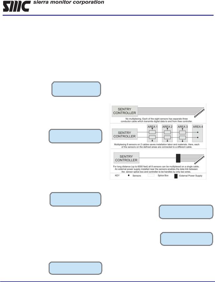
Multiplexing of digital signals from the sensors to the controller on a common cable reduces installation cost. Up to eight sensors can be multiplexed on a single cable. Since each sensor has a unique address, the controller can communicate with the sensors in turn. Also, with optional external power supplies to the sensors, two-wire communication with the controller reduces the installation costs and increases the distance allowed between the controller and the sensor modules.
Record Keeping made Easy
Reports can be printed via an optional forty-column printer. There are six types of reports available.
Status Report – a snap– shot of gas concentrations and alarm conditions that can be pre-set to print hourly, daily, weekly or on demand.
System Report – lists all the system parameters including configuration of the software, calibration, printer and sensor modules.
PRESENT CONFIG.: STATUS = 07 DAYS
PRESS ENTER TO: [SYSTEM REPORT]
Key Event Report – prints when any sensor module reading exceeds a pre-set threshold level, which may or may not be an alarm level. After the module is above the minimum level, any change greater than a preset, selectable concentration change will cause another Key Event Report to print.
Sierra Monitor Corp. 1991 Tarob Ct., Milpitas, CA 95035, USA, 408-262-6611, 800-727-4377, FAX: 408-262-9042
Web Site: http://www.sierramonitor.com |
E-Mail: sales@sierramonitor.com |
|
© 2009 by Sierra Monitor Corporation |
 Loading...