

Page 1
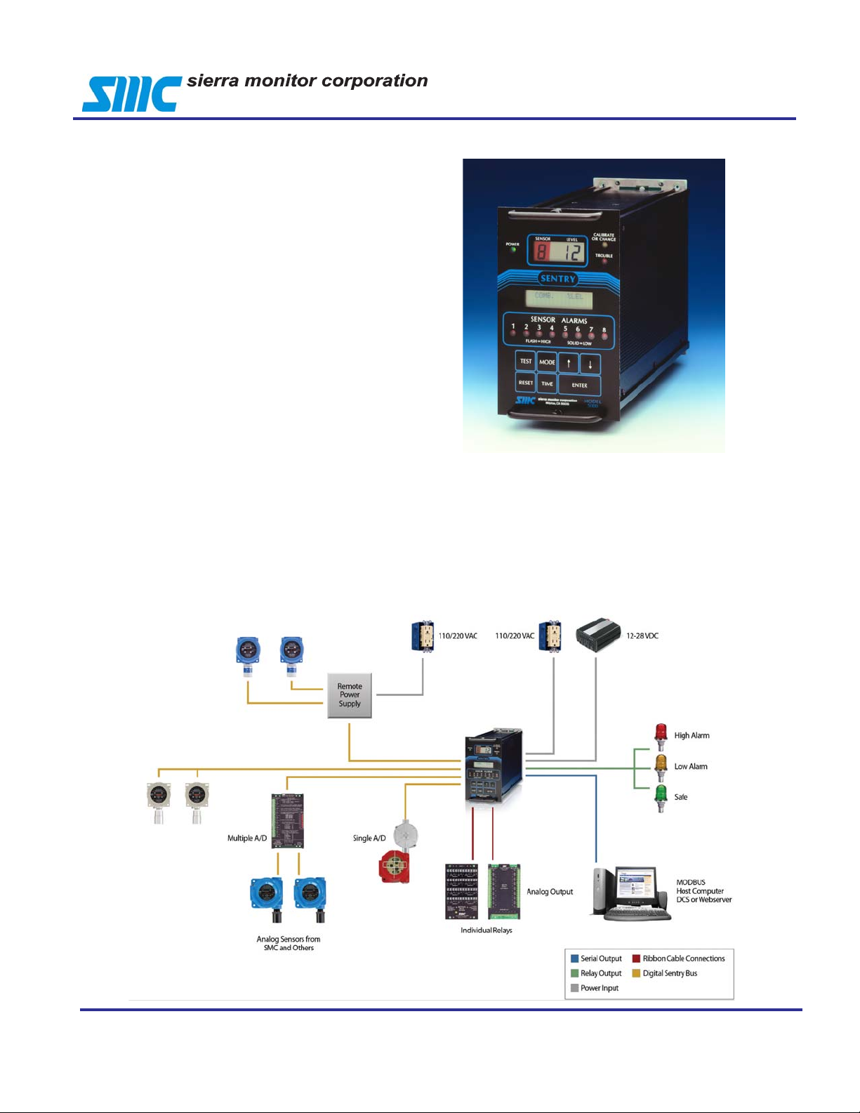
The Sentry controller is the heart of the Sentry Gas Risk
Management system. It is a microprocessor based system that performs functions including management of the
sensor modules, management of alarm relays and interface with the user via the front panel display , printer output, Modbus digital communication, alarm indicators and
relay outputs.
Sentry system two-way communication between the sensors and the controller results in the capability to perform
one-person calibration and diagnostic checks from the
controller. The user-friendly front panel includes a large
display of the gas concentration and sensor number. V arious scan modes are available to meet the user’s specific
monitoring needs. A separate 2-line alphanumeric display provides more detailed information including sensor
data, error messages and menu prompting for calibration
and set-up.
Sentry
Controller
A series of alarm LEDs instantly inform the user of alarm
status on any of the eight sensors interfaced to the controller. These LEDs are solid for low alarm and flashing for
high alarm. A trouble LED warns that one of 120 diagnostic checks has detected a problem. More information about
the trouble will be displayed on the alphanumeric display .
A calibrate/change LED indicates that calibration or con-
figuration change is being performed on at least one sensor. The remaining sensors will remain on-line providing
continuous protection.
The Sentry keypad, together with the user-friendly menu
on the alphanumeric display , guides the user through setup, calibration and maintenance of the Sentry system.
Sierra Monitor Corp. 1991 T arob Ct., Milpitas, CA 95035, USA, 408-262-661 1, 800-727-4377, F AX: 408-262-9042
Web Site: http://www.sierramonitor.com E-Mail: sales@sierramonitor.com
© 2009 by Sierra Monitor Corporation
Page 2
FEATURES AND BENEFITS
Sentry Controller
Gas Risk Management is the key design philosophy behind SENTRY. The user can employ those features that
are most important for a specific application, and, as the
application needs grow or change, the system can be
reconfigured at the keyboard to satisfy expanded requirements.
Menu Prompting
Menu prompting guides the user through system configuration and operation.
Prompting, via the alphanumeric display , keeps the full
range of capabilities at the
operator’s fingertips. When
it is necessary to modify the
system, prompting will enable the change to be handled
quickly and correctly .
USE ARROWS/ENTER
HIGH ALARM = 20
System Security
User identification codes prevent unauthorized users from
changing the configuration and identify those
users who have made
changes. Up to eight
user codes may be as-
USE ARROWS/ENTER
ENTRY CODE = 1234
Diagnostics
An internal self-diagnostic routine makes over 120 checks
of operating parameters to ensure the system is performing properly. System performance measurements and key
reference voltages can be accessed and presented at the
switches automatically to display those sensors in alarm. HIGH-
EST sensor scan will automatically display the sensor recording the highest gas reading - alternately for each gas type. The
user can also SELECT SENSOR displays for a sensor of particu-
lar interest.
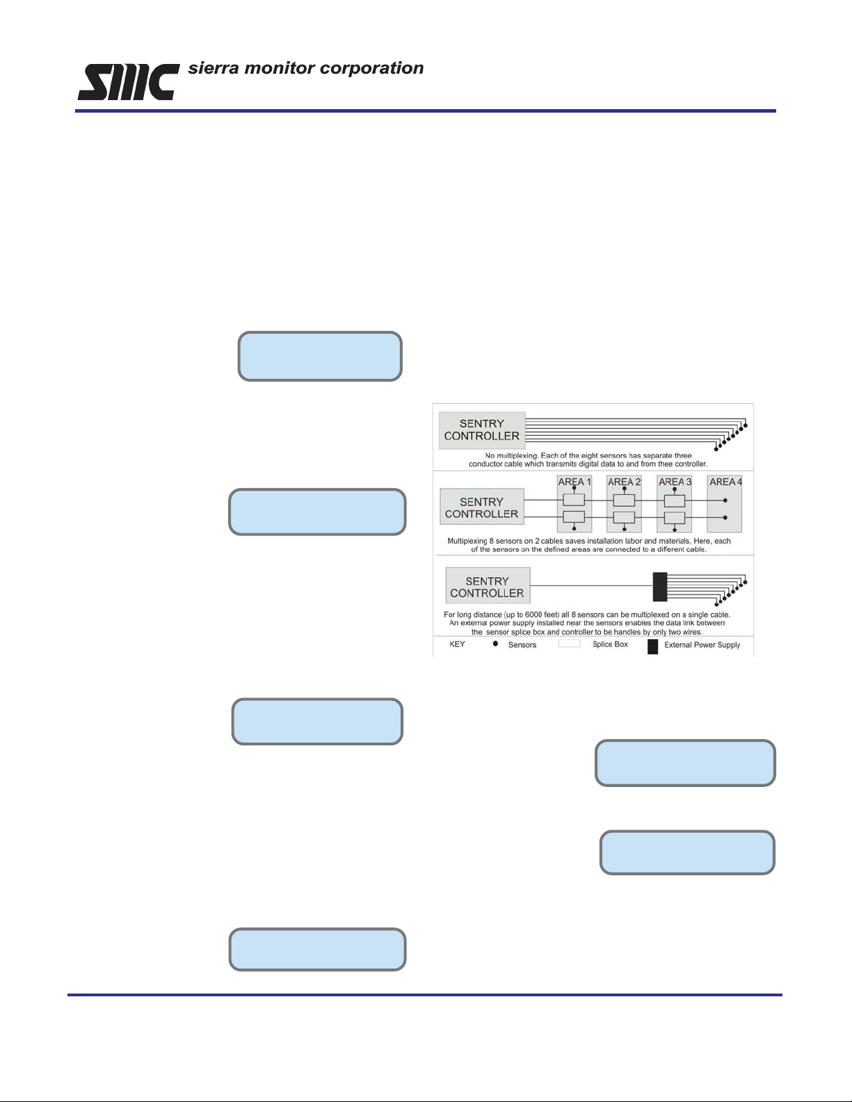
Reduced Installation Costs
Multiplexing of digital signals from the sensors to the controller
on a common cable reduces installation cost. Up to eight sensors can be multiplexed on a single cable. Since each sensor
has a unique address, the controller can communicate with the
sensors in turn. Also, with optional external power supplies to
the sensors, two-wire communication with the controller reduces
the installation costs and increases the distance allowed between the controller and the sensor modules.
A TEST function on the front panel allows testing of the
alarms, system and display. Warning messages on the
alphanumeric display
alert users that a condition
requires attention without
causing a system failure
or interruption.
During calibration Sentry performs a dynamic range check
on every sensor to insure its resolution is sufficient to give
an accurate reading. Sentry avoids false alarms by locking
out sensor alarms during calibration and not allowing excessive amplification of the signal.
COMB. % LEL
FAST ERROR CHECK
Sensor Scan Display
Current sensor gas exposure readings can be viewed continuously in any one of four scan modes. CONTINUOUS
scan displays each sensor in turn.
SAFE scan mode displays
CONDITION SAFE and,
upon an alarm condition,
CONDITION
[SAFE]
Record Keeping made Easy
Reports can be printed via an optional forty-column printer. There
are six types of reports available.
Status Report – a snap–
shot of gas concentrations
and alarm conditions that
can be pre-set to print hourly,
daily, weekly or on demand.
PRESENT CONFIG .:
ST A TUS = 07 DA YS
System Report – lists all
the system parameters including configuration of the software, calibration, printer and
sensor modules.
PRESS ENTER TO:
[SYSTEM REPORT]
Key Event Report – prints when any sensor module read-
ing exceeds a pre-set threshold level, which may or may not be
an alarm level. After the module is above the minimum level,
any change greater than a preset, selectable concentration
change will cause another Key Event Report to print.
Sierra Monitor Corp. 1991 T arob Ct., Milpitas, CA 95035, USA, 408-262-661 1, 800-727-4377, F AX: 408-262-9042
Web Site: http://www.sierramonitor.com E-Mail: sales@sierramonitor.com
© 2009 by Sierra Monitor Corporation
Page 3

Sentry Controller
History Report – lists the last time each significant event
has occurred. Includes
system power interruption, history reset, alarm,
concentration and calibration information for
each sensor module.
USE ARROWS/ENTER
PRINT HISTORY : YES
Calibration Report – prints automatically when calibra-
tion is completed.
Diagnostic Report – lists the critical voltage conditions
for each module and can
be selected to print periodically.
H2S PPM
DIAGNOSTIC SCAN
Relay Logic for Customized Response
Standard Relays- the controller has DPDT dry contact
relays for low alarm, high alarm, and trouble. Any one sensor
can activate the appropriate relay.
Individual Relays – If separate relay action is required for
each sensor, then the individual relay option is appropriate.
This option provides individual SPDT dry contact relays for
each alarm level for all sensor modules.
Options to Expand System Flexibility
Battery Back-Up
The battery back-up system provides operating power when
AC power drops below 90 V AC. Includes battery, AC line filter,
two battery charging modes, and a 12 to 24 VDC converter.
Sensor Modules
Sensor modules available for a wide range of gases;
Combustible Gas* Sulfur Dioxide
Oxygen* Nitrogen Dioxide
Hydrogen Sulfide* Hydrogen Chloride
Carbon Monoxide* Hydrogen Cyanide
Chlorine* Ammonia*
Hydrogen Nitric Oxide
Hydrogen Fluoride Methane / Propane
* Refer to IT Series Data Sheet
Analog Input
The analog input modules, 5100-90 and 5100-99 enable the
user to use any sensing device that produces a 4-20 mA DC
signal to communicate with Sentry through an Analog/Digital
signal converter.
Output Expansion Module
The output expansion module provides the same capacity as
the individual Relay Panel, plus it provides 4-20 mA DC outputs proportional to the concentration for each sensor module.
Custom Configuration Relays – the custom configu-
ration relay option permits decision logic before actuating the
relays. Any group of sensors in the same vicinity can actuate
the relay designated for that vicinity (zone).
Software Enhancement Package
The Software Enhancement Package provides the Sentry system with powerful software features by selecting from a menu
of factory set options. These features include:
• MODBUS protocol
Provides the MODBUS protocol software to interface with
a wide variety of third party software. (Other protocols
avalibale)
• Factory Edit Gas Tags and Module Tag
The tags normally selected by the user can be built-in
as default tags
• Enhanced alarm acknowledgment features
Provides high and low alarm acknowledgement and an
emergency alarm (third alarm) feature
Calibration Systems
Calibration gas can be delivered from a central panel through
permanently installed tubing to the sensors. Since Sentry’s
calibration adjustment is performed in software, it is not necessary to make mechanical adjustments at the sensor. Alternatively individual gas delivery lines can be located near the
sensors.
Sierra Monitor Corp. 1991 T arob Ct., Milpitas, CA 95035, USA, 408-262-661 1, 800-727-4377, F AX: 408-262-9042
Web Site: http://www.sierramonitor.com E-Mail: sales@sierramonitor.com
© 2009 by Sierra Monitor Corporation
Page 4

MODE
EXPLOSION-PROOF
ACDCT
C
POWER
OR CHANGE
CALIBRATE
S
MODEL
T
T
8
SENTRY
M
INSIDE VIEW
INSTRUMENT RACK
GENERAL SPECIFICATIONS
Sentry Controller
Operating
Power (Standard): 120VAC+10%/-15%, 60 Hz
12 VDC Nom; 10 to 29 VDC
Power (Optional): 220 VAC +10%-15%, 50 Hz
12 VDC Nom; 10 to 29 VDC
Power consumption: 48-Watts nominal
Number of Channels: 2, 4 or 8
Operating Temperature: 320 to 1220 F (00 to 500 C)
0
Storage Temperature: -40
Humidity: 10% to 95% RH
Relays (Standard): Three DPDT 3A, 1 15 V A C
(Ind. Relay Option): 16 SPDT 6A, 115 VAC
(Custom Relay Option): 16 SPDT 6A, 1 15 V AC
(Output Expansion): 16 SPDT 6A, 115 VAC
Analog Outputs: 4-20 mA Current Source
Displays: 4 digit ½” LCD
RS-232 Port: Standard Printer
to 1310 F (-400 to 550 C)
Loop Resistance 800 Ohms Max.
32 character (2x16)
alphanumeric LCD
Option MODBUS
Physical
Dimensions:
Rack Mounted: 7.0” x 4.5” x 12.0” (HxWxD)
17.5 x 1 1.2 x 30.0 cm
NEMA 4X Enclosure: 17.5” x 16.2” x 6.3” (HxWxD)
44.5 x 41.1 x 16.0 cm
NEMA 7 Enclosure: 22.0” x 21.5” x 14.0” (HxWxD)
55.9 x 54.6 x 35.6 cm
Weight:
Rack Mounted: 7.0 pounds (3.2 kg)
NEMA 4X Enclosure: 25.0 pounds (11.3 kg)
NEMA 7 Enclosure 143.0 pounds (65.0 kg)
Approvals: FM Approved, CE Mark
Mounting
Rack Mounted: Shelf for insertion in
Instrument Cabinet
Panel Mounted Panel bracket, bezel
NEMA 4X Enclosure: Wall or vertical surface
NEMA 7 Enclosure: Explosion Proof, Class 1, Div I,
Group C & D
SENSOR LEVEL
TROUBLE
8 88
INFORMAT ION
DISPLAY
ENSOR ALARMS
12345678
FLASH=HI GH SOLID=LOW
ESTMODE
IMEENTERRESET
ilpitas, CA 950 35
ROUBLETROUBL E HIGH HIGH LOW LOW
H N G + - N/C C N/O N/OCN/C N/OCN/C N/OCN/C N/OCN/C N/OCN/C
PSG GSPGSPGSPGSPGSPGSPGSP
HANNEL 1CHANNEL 2CHANNEL 3CHANNEL 4CHANNEL 5CHANNEL 6CHANNEL 7CHANNEL 8
5000
CALIBRATE
OR CHANGE
LEVELSENSOR
POWER
TROUBLE
SENTRY
SENSOR ALARMS
SOLID=LOWFLASH=HIGH
TEST
RESET TIME ENTER
87654321
NEMA 4X NEMA 7
ORDERING INFORMATION
5000-02 Sentry 2-channel Controller*
5000-04 Sentry 4-channel Controller*
5000-08 Sentry 8-channel Controller*
4314-01 Output Expansion Module
5392-00 Individual Relay Panel
5392-01 Custom Configuration Relay Panel
5398-50 Software Enhancement Package
5398-21 Sample Draw System –1 Channel
5398-24 Sample Draw System –4 Channel
5301-XX Printer Packages
5100-02 Sensor Module – Combustible Gas*
5100-03 Sensor Module – Oxygen*
5100-04 Sensor Module – Carbon Monoxide*
5100-05 Sensor Module – Hydrogen Sulfide*
SWITCHES
PRINTER
RACK MOUNT
5100-06Sensor Module – Chlorine*
5100-07Sensor Module – Hydrogen
5100-10Sensor Module – Sulfur Dioxide
5100-12Sensor Module – Nitrogen Dioxide
5100-16Sensor Module – CO (H
5100-19Sensor Module – Nitric Oxide
5100-21Sensor Module – Hydrogen Chloride
5100-22Sensor Module – Hydrogen Cyanide
5100-25Sensor Module – Ammonia*
5100-26Sensor Module – Hydrogen Fluoride
5100-28Sensor Module – Methane*
5100-90Analog/Digital Input Module (8-channel)
5100-99Analog/Digital Input module (1-channel)
* Refer to IT Series Data Sheet
tolerant)
2
Sierra Monitor Corp. 1991 T arob Ct., Milpitas, CA 95035, USA, 408-262-661 1, 800-727-4377, F AX: 408-262-9042
Web Site: http://www.sierramonitor.com E-Mail: sales@sierramonitor.com
© 2009 by Sierra Monitor Corporation
 Loading...