

TF 11,TF 12,TF 21,TF 22,TF 31,TF 32,TF 41,TF 42,TF 13,TF 23,TF 33,TF 43,TB 12,TB 13,TB 22,TB 23,TB 32,TB 33,TB 42,TB 43
Sierra TF 11,TF 12,TF 21,TF 22,TF 31,TF 32,TF 41,TF 42,TF 13,TF 23,TF 33,TF 43,TB 12,TB 13,TB 22,TB 23,TB 32,TB 33,TB 42,TB 43 Technical And Installation Manual

RADIATORE CONVETTIVO
CONVECTOR RADIATOR
thermofon
®
MANUALE TECNICO E D’INSTALLAZIONE - TECHNICAL AND INSTALLATION MANUAL

INFORMAZIONI GENERALI
Questo manuale descrive il terminale qui rappresentato.
Si consiglia di conservare questo manuale almeno 10 anni per eventuali riferimenti futuri e in un
luogo asciutto per evitarne il deterioramento.
Leggere attentamente e completamente tutte
le informazioni contenute in questo manuale.
Prestare particolarmente attenzione alle norme
d’uso accompagnate dalle scritte “ATTENZIONE”
in quanto, se non osservate, possono causare
danno al termoconvettore e a persone e/o cose.
SIERRA S.p.A. declina ogni responsabilità per
qualsiasi danno dovuto ad un uso improprio del
terminale e ad una lettura parziale o superfi ciale
delle informazioni contenute in questo manuale.
Il numero di pagine di questo manuale è: 14.
GENERAL INFORMATION
This manual describes the unit.
Store the manual in a dry location to avoid deterioration, as it must be kept for at least 10 years for any
future reference.
All the information in this manual must be carefully read and understood. Pay particular attention to
the operating standards with “WARNING” signals as
their disrespect can cause damage to the machine
and/or persons or objects.
SIERRA S.p.A. declines all responsibility for any damage whatsoever caused by improper use of the
machine, and a partial or superfi cial acquaintance
with the information contained in this manual. This
manual has 14 pages.
INDICE / INDEX
Informazioni generali • General information...................……………………………...............1
Caratteristiche • Features……….........…………………………………………………...........2
Componenti principali • Main components......................................................................................3
Imballo • Packaging….……………………………..…………….……………………………….
Descrizione dei componenti • Description of components...........……………........……….4
Dati tecnici e dimensionali • Technical and dimensional data..…………….…………....6
Resa termica al variare della temperatura • Heating capacity depending on the temperature…..7
Installazione dell’unità • Installation of the unit………………………………………………..9
Sostituzione di radiatori • Substituting for an existing radiator…..…..............……….…12
Versioni automatiche con termostato (TFXX A/R) • Automatic vent versions (TFXX A/R)…..13
Trasporto • Carriage…………....……………………………………………………………..14
Usi impropri • Improper use……………...………. ………………………………………..14
1

2
CARATTERISTICHE
DESCRIZIONE DELL’UNITÀ
Il termoconvettore Thermofon® concentra elevate caratteristiche tecnologiche e funzionali che
ne fanno il terminale ideale per il riscaldamento
di ogni ambiente. L’erogazione di calore avviene
per convezione naturale, grazie ad un esclusivo
scambiatore alettato. L’erogazione di calore è immediata e distribuita in modo uniforme in tutto
il locale; Thermofon
® genera calore se inserito
in un impianto termico alimentato con caldaia,
teleriscaldamento o pompa di calore. La chiusura
del defl ettore superiore interrompe quasi totalmente l’erogazione di calore e, nei periodi in cui
non è necessario il riscaldamento, impedisce alla
polvere e a corpi estranei di penetrare all’interno.
La possibilità di rimuovere con facilità il mantello
di copertura consente di eseguire una pulizia accurata delle parti interne, condizione necessaria
per l’installazione in luoghi molto affollati o che
richiedono uno standard elevato di igiene.
Facilità di installazione con attacchi idraulici reversibili in fase di installazione; idoneità a sostituire radiatori pre-esistenti con interasse compreso tra 480 e 630 mm. Pieno rispetto delle norme
antinfortunistiche e di sicurezza.
FEATURES
DESCRIPTION
The Thermofon® radiator-convector combines
advanced technical and operational characteristics, which make it the ideal unit for residential
heating. The excellent heat distribution is due to
natural convection by using an exclusive fi nned
heat exchanger. The heated air is immediately deli-
vered to the entire room; the Thermofon
® produ-
ces warm air when fi tted to heating system with a
boiler or a heat pump. When the vent is closed, the
heat distribution is almost completely interrupted.
In addiction, during the seasons where heating
is not required, it prevents dust and other objects
from entering the unit. The removable and light cover enables thorough cleaning of the unit, essential
for installations in venues subject to crowding or in
those with special hygienic requirements.
The Thermofon
® is easy to install, and reversible
water connections allow to the choice of a left or
right hand installation; Thermofon
® can also
replace radiators with a distance from “water-in
pipe” to “water-out pipe” from 480 to 630 mm. The
Thermofon
® is in full compliance with the safety
regulations.
3
VERSIONI DISPONIBILI
Il termoconvettore Thermofon® è disponibile
in 8 granddezze, 20 modelli e 4 versioni per ogni
modello.
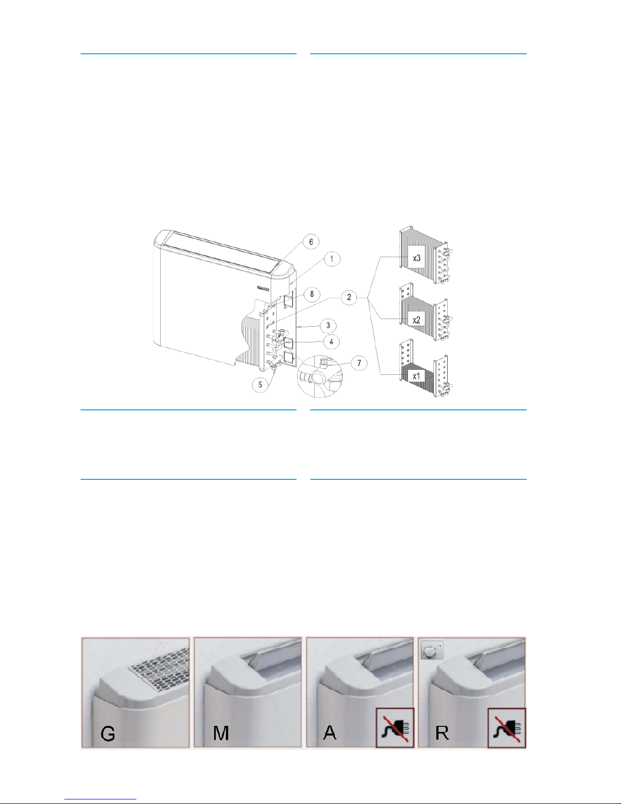
Versioni (mobile con colore standard RAL 9002):
G: con griglia fi ssa
M: con defl ettore ad apertura/chiusura manuale
A: con defl ettore automatico e termostato incor-
porato
R: con defl ettore automatico e termostato remoto
VERSIONS AVAILABLE
Thermofon® convectors are available in 8 sizes,
20 models and 4 versions for each model.
Versions (standard body color is RAL 9002):
G: fi xed grid
M: manual adjustable vent
A: automatic vent with onboard thermostat
R: automatic vent with remote thermostat
COMPONENTI PRINCIPALI
1 Mantello di copertura
2 Batteria di scambio termico (reversibile)
3 Schienale posteriore di fi ssaggio a parete
4 Collettore ingresso acqua
5 Collettore uscita acqua
6 Testata con defl ettore ad apertura regolabile (o
griglia)
7 Valvola sfi ato aria
8 Convogliatore di fl usso d’aria
MAIN DESCRIPTION
1 Cover
2 Heat exchange coil (reversible)
3 Rear frame for mounting against the wall
4 Inlet water connection
5 Outlet water connection
6 Air distribution head with adjustable slat (or fi xed
grid)
7 Air bleeder
8 Air conveyor
IMBALLO
I termoconvettori vengono spediti con imballo
standard in cartone.
PACKAGING
The units are shipped in a standard card board box.

DESCRIZIONE DEI COMPONENTI
1 MANTELLO DI COPERTURA
La sua forma arrotondata unisce alla gradevole
estetica maggior sicurezza contro gli urti accidentali. Disponibile in colore RAL9002, è realizzato in lamiera verniciata a caldo con polveri poliuretaniche dopo trattamento di passivazione per
garantire alta resistenza e durata nel tempo.
2 BATTERIA DI SCAMBIO TERMICO
Progettata e studiata per esaltare al massimo l’effetto convettivo naturale, è realizzata con tubi di
rame ed alettatura speciale in alluminio bloccati
mediante espansione meccanica dei tubi. La batteria di scambio termico è reversibile, ossia è possibile il collegamento idraulico a destra oppure a
sinistra.
3 SCHIENA DI FISSAGGIO POSTERIORE
È realizzata in lamiera zincata di forte spessore,
dotata di fori per il fi ssaggio al muro e apposite
sezioni (pretranciate) per il passaggio delle tubazioni idrauliche su entrambi i lati. Le zone di
passaggio tubi (pretranciate) poste sulla parte
superiore, consentono la sostituzione di radiatori
(versioni TF) con interasse compreso tra 480 fi no
a 630 mm.
4-5 COLLEGAMENTI IDRAULICI
I collegamenti sono ad attacco femmina ½”. Data
la possibilità di ruotare la batteria, è possibile prevederne la disposizione a destra oppure a sinistra.
(4: attacchi ingresso acqua; 5: attacchi uscita acqua
dallo scambiatore di calore).
6 TESTATA
Realizzata in materiale termoplastico ad elevata
resistenza, è disponibile con griglia metallica fissa (G) oppure con pala di apertura/chiusura sia
manuale (M) che motorizzata (A). Nella versione
(A) con pala motorizzata, l’apertura della pala
viene comandata dal consenso del termostato a
corredo dell’unità, a seconda del valore di tempe-
ratura impostato dall’utente. Colore: RAL 7044.
7 VALVOLA DI SFIATO ARIA
È posta sul collettore superiore della batteria. Permette lo sfi ato dell’aria dalla batteria.
8 CONVOGLIATORE DI FLUSSO ARIA
Ottimizza il fl usso d’aria ascendente, esaltando
l’effetto convettivo naturale.
DESCRIPTION OF THE PARTS
1 CABINET HOUSING
The rounded cabinet combines aesthetic appeal
with safety against accidental impact. Available in
RAL 9002 colour, it’s made of hot painted steel panels with polyurethane powder after passivation
treatment against rust and corrosion.
2 HEAT EXCHANGER COIL
Researched and designed in order to exploit the
natural convective thermal exchange, the coil is a
copper pipe coil with aluminium fins mechanically
fitted by expansion of the pipes. The coil can be re-
versed on site.
3 REAR BEARING FRAME
The frame is made from suitably thick sheet metal
and is galvanised to ensure protection against corrosion.
The rear of the frame has holes for wall mounting
the appliance and pre-blanked holes on both sides
to allow the passage of the hydraulic pipework.
The pre-blanked holes in the upper side allow the
substitution of existing radiators (TF version) with
a distance from “water-in pipe” to “water-out pipe”
from 480 to 630 mm.
4-5 WATER CONNECTIONS
The connections are provided with female joints
(1/2”). Since it’s possible to reverse the heat exchanger, it is possible to connect them on the right side
or on the left side of the rear bearing frame. (4: inlet
water connection; 5: outlet water connection).
6 AIR DISTRIBUTION HEAD
Constructed in high temperature-resistant plastic,
is available in three models: G – with fi xed steel me-
tal grid; M – with adjustable vent; A – with automatic vent. The A version is equipped with an electric
motor (C.C. – 6 V - supplied by a common 9 volts
battery) that opens or close the vents. The opening/
closing input is given from an on-board thermostat,
set by the user. Colour: RAL 7044.
7 BLEED VALVE
The bleed valve is positioned at the top of the heat
exchanger coil.
8 AIR CONVEYOR
The air conveyors, on both sides, optimise the ascending airfl ow, maximizing the natural convective heat
fl o w .
4
 Loading...