

Page 1
Innova-Switch™ Series
615 Series Mass Flow/ Level Switch
Instruction Manual
Part Number: Im-615, Rev. B, July 2010
CCOORRPPOORRAATTEE HHEEAADDQQUUAARRTTEERRSS
5 Harris Court, Building L, Monterey, C A 93 940 U.S.A.
Phone (831) 373-0200 Toll Free (800) 866-0200 Fax (831) 373-4402
www.sierrainstruments.com
EEUURROOPPEEAANN HHEEAADDQQUUAARRTTEERRSS
Bijlmansweid 2, 1934RE Egmond aan den Hoef
The Netherlands
Phone +31 72 5071400 Fax +31 72 5071401
AASSIIAA--PPAACCIIFFIICC HHEEAADDQQUUAARRTTEERRSS
RM. 618, Tomson Centre, Bldg. A, 188 Zhang Yang Road
Pu Dong New District, Shanghai, P. R. China
Phone +8621 5879 8522 Fax +8621 5879 8586
Page 2

Sierra Instruments Innova-Switch™ Instruction Manual
© COPYRIGHT SIERRA INSTRUMENTS 2010
No part of this publication may be copied or distributed, transmitted, transcribed, stored in a retrieval system, or
translated into any human or computer language, in any form or by any means, electronic, mechanical, manual, or
otherwise, or disclosed to third parties without the express written permission of Sierra Instruments. The information
contained in this manual is subject to change without notice.
TRADEMARKS
Innova-Swtich™ is a registered trademark of Sierra Instruments, Inc. Other product and company names listed in
this manual are trademarks or trade names of their respective manufacturers.
i
Page 3

Sierra Instruments Innova-Switch™ Instruction Manual
IMPORTANT CUSTOMER NOTICE
Before installing and operating the flow meter, please read this manual carefully and follow its instructions.
¾ Sierra has verified the conformity between the contents in this manual and the hardware and software
described. However, errors may still exist. We regularly review the materials covered in this manual and
correct errors with revisions. Any suggestions for improvement will be appreciated.
¾ Go to www.sierrainstruments.com/products/downloads.html for a most current electronic version of this
manual.
¾ We reserve the right to change the content of this manual without prior notification.
¾ If you have any questions or problems regarding this manual, please contact Sierra’s Customer Service
Department:
Toll Free: 800-866-0200 Phone: +831-373-0200 Fax: 831-373-4402
Email: service@sierrainstruments.com
WARNINGS IN THIS MANUAL
Caution and warning statements are used throughout this book to draw your attention to important information.
WARNINGS
“Warning” indicates that ignoring the relevant
requirements or precautions may result in
personal injury or flow meter damage.
NOTES
“Note” indicates that ignoring the relevant
requirements or precautions may result in flow
meter damage or malfunction.
BEFORE STARTING
ii
Page 4

Sierra Instruments Innova-Switch™ Instruction Manual
Sierra Instruments appreciates your choosing our product for your liquid level or liquid/gas flow
switching application. We are committed to providing reliable, quality instrumentation to our customers.
To ensure the maximum and intended benefit of this instrument, we encourage you to read this brief
operation and maintenance manual in its entirety prior to unpacking and installing the unit.
The following precautions should be noted immediately:
φ WHEN INSTALLING YOUR SIERRA INNOVA-SWITCH™ INTO A PIPE OR VESSEL USE A 1
1/8 INCH (28.575mm) OPEN-END OR ADJUSTABLE WRENCH TO TIGHTEN AT THE HEX
FLATS OF THE MNPT OF A STANDARD SWITCH. (IF YOU HAVE A NON-STANDARD
SWITCH AN ALTERNATE SIZE WRENCH MAY BE REQUIRED). DO NOT USE THE
INSTRUMENT HEAD TO TIGHTEN THE SWITCH TO THE MOUNTING PORT. ROTATION
OF THE INSTRUMENT HEAD WITH RESPECT TO THE SENSOR BODY CAN CAUSE
INTERNAL WIRING DAMAGE (SEE FIGURES 1).
φ THE SWITCH BODY MUST BE ORIENTED TO HAVE THE TWIN SENSORS PARALLEL TO
THE LEVEL BEING DETECTED WHEN THE SENSOR IS INSTALLED HORIZONTALLY FOR
POINT LEVEL APPLICATIONS. LIKEWISE, FOR FLOW APPLICATIONS, THE SWITCH
BODY MUST BE ORIENTED TO HAVE THE TWIN SENSORS PERPENDICULAR TO THE
FLOW BEING DETECTED. DUE TO THE PIPE THREAD MOUNTING, IT MAY BE
NECESSARY TO MAKE A TRIAL FIT, ADD OR REMOVE TEFLON TAPE OR OTHER PIPE
THREAD SEALANT, AND REINSTALL TO ACHIEVE A SATISFACTORY SEAL WITH THE
SENSORS PROPERLY ORIENTED. FOR VERTICAL INSTALLATION OF SENSORS FOR
POINT LEVEL DETECTION THE ORIENTATION MAKES NO DIFFERENCE. PROPER
ORIENTATION IS MARKED ON THE SWITCH BODY FOR REFERENCE (SEE FIGURE 5).
φ A GROUND WIRE MUST BE ATTACHED TO THE GROUND SCREW LOCATED INSIDE THE
INSTRUMENT ENCLOSURE FOR PROPER OPERATION. FOR CENELEC/CE OPTION THE
GROUND SCREW IS LOCATED OUTSIDE THE BODY OF THE INSTRUMENT ENCLOSURE
(SEE FIGURE 6).
φ BE SURE TO APPLY THE PROPER VOLTAGE AS CONFIGURED AT THE FACTORY. DO
NOT APPLY 115 VAC TO 24 VDC VERSIONS OR 24 VDC TO 115 VAC VERSIONS.
(LIKEWISE 230 VAC).
φ FOR OPTIMUM OPERATION, CALIBRATION MUST BE ACCOMPLISHED AT ACTUAL
PROCESS TEMPERATURE AND PRESSURE CONDITIONS IN GASES AND AT ACTUAL
PROCESS TEMPERATURE CONDITIONS IN LIQUIDS.
φ TO ENSURE ACCURATE CALIBRATION AND AVOID SET POINT DRIFT, IT IS IMPERATIVE
THAT A MINIMUM OF 10 MINUTE WAIT BE OBSERVED AFTER POWER IS APPLIED TO
ALLOW THE SENSOR TO WARM-UP TO THE AMBIENT FLUID TEMPERATURE.
LIKEWISE, WHEN ADJUSTING THE ZERO, SPAN, AND SET POINTS POTS, A MINIMUM
iii
Page 5

Sierra Instruments Innova-Switch™ Instruction Manual
OF 30 SECONDS SHOULD BE OBSERVED TO ALLOW FOR STABILIZATION OF
TEMPERATURE.
φ DO NOT SANDBLAST OR ABRASIVE CLEAN THE SENSING PROBES. THE SENSING
PROBES COULD BE DAMAGED BY ABRASIVES.
ALL DIMENSIONS GIVEN IN THIS MANUAL ARE IN INCHES (AND MILLIMETERS).
If you have any questions prior to or during installation and calibration, please do not hesitate to call the
factory for assistance. We want to ensure the very best possible installation and operational results for
your benefit.
NOTICE
This manual covers the following model numbers:
Innova-Switch™ Series Models 615- FS4200 615-LS3200
Agency Approvals Explosion-Proof rating Mass Flow Switch Point Level Switch
CENELEC EEx d IIB T4 (Killark Enclosure)
European EEx d IIC T4 (Akron Electric Enclosure) FS42CN LS32CN
See Figure 1A and 1B
CSA T4A
Canadian Standards Class I, Group B,C,D FS42CS LS32CS
Class II, Group E,F,G
(Both Akron Electric and Killark)
Non-Approved Non-Explosion Proof FS42NX LS32NX
Switch Kits
(No Enclosures) Not Rated FS42SK LS32SK
(Ref. Section
CE 3.2.3 wiring) EMC Directive: 89/336/EEC Option – CE Option -CE
iv
Page 6
Sierra Instruments Innova-Switch™ Instruction Manual
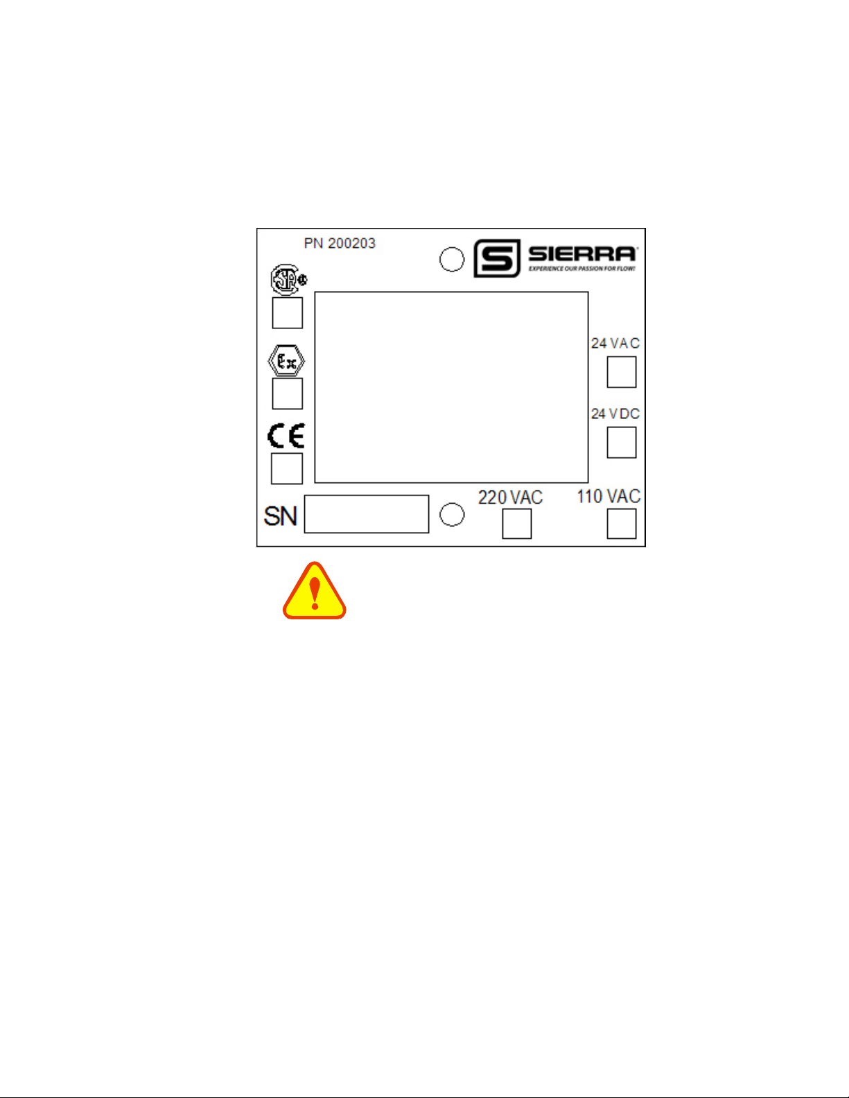
SPECIAL NOTICE
The electronic assemblies contained in the Innova-Switch™ models are configured for specific
voltages and have specific modifications to accommodate the various agency approvals. When
ordering spare electronics, replacements, or exchanges in the field please ensure you identify the
specific configuration you have by noting the boxes marked on the transformer configuration tag.
*WARNING*
THE WETTED SENSOR OF THE SWITCH IS OF AN ALL WELDED CONSTRUCTION
CREATING A PRESSURE BOUNDARY FROM THE PROCESS FLUID (LIQUID OR
GAS). ANY BREACH OF THIS BOUNDARY THROUGH CORROSION,
MISTREATMENT, OR MISAPPLICATION COULD ALLOW THE PROCESS FLUID TO
ENTER THE ENCLOSURE OF THE UNIT.
PROCEED WITH CAUTION WHEN OPENING THE ENCLOSURE AFTER A BREACH OF
THE PRESSURE BOUNDARY TO AVOID CONTACT WITH ANY PROCESS FLUIDS THAT
MAYBE CONTAINED WITHIN THE ENCLOSURE.
*CAUTION*
IF THE FLUID PROCESS TEMPERATURE EXCEEDS 40 DEG C, THIS INSTRUMENT
CANNOT BE USED IN AN EXPLOSION PROOF APPLICATION UNLESS THE IGNITION
TEMPERATURE OF THE FLUID ATMOSPHERE IS A MINIMUM OF 80 DEG C HIGHER
THAN THE PROCESS TEMPERATURE.
v
Page 7

Sierra Instruments Innova-Switch™ Instruction Manual
TABLE OF CONTENTS
1.0 INTRODUCTION
2.0 DESCRIPTION
2.1 LEVEL SWITCHING
2.2 FLOW SWITCHING
3.0 INSTALLATION
3.1 MECHANICAL INSTALLATION
3.2 ELECTRICAL INSTALLATION
3.2.1 LOCAL ELECTRONICS (LE OPTION/STANDARD)
3.2.2 REMOTE ELECTRONICS (RE) OPTION
3.2.3 CE OPTION FILTER BOARD CONNECTOR PLATE WIRING (CE OPTION)
4.0 OPERATION AND CALIBRATION OF THE INNOVA-SWITCH™ FOR FLOW APPLICATIONS
4.1 PRE-OPERATIONAL CHECKS
4.2 L.E.D. AND RELAY STATUS LOGIC (FAIL-SAFE)
4.3 CALIBRATION – FLOW
5.0 OPERATION AND CALIBRATION OF THE INNOVA-SWITCH™ FOR POINT LEVEL
APPLICATIONS
5.1 PRE-OPERATIONAL CHECKS
5.2 L.E.D. AND RELAY STATUS LOGIC (FAIL-SAFE)
5.3 CALIBRATION – LEVEL
6.0 MAINTENANCE AND TROUBLE SHOOTING
6.1 CLEANING
6.2 TROUBLE SHOOTING
6.2.1 POWER AND CONTINUITY VERIFICATION
6.2.2 SENSOR/ELECTRONICS FUNCTIONALITY VERIFICATION
6.2.3 SET POINT DRIFT
7.0 SPECIFICATIONS
8.0 WARRANTY AND SERVICE
8.1 WARRANTY
8.2 SERVICE
vi
Page 8

Sierra Instruments Innova-Switch™ Instruction Manual
9.0 APPENDIX
9.1 VOLUME FLOW CONVERSION CHART
9.2 FLOW CONVERSION CHART
9.3 FLOW OF WATER THROUGH SCHEDULE 40 STEEL PIPE (AVAILABLE IN PRINTED
MANUAL ONLY)
10 OPTIONS
10.1 LIVETAP (LT)
10.2 VARIABLE INSERTION (VI)
10.3 SANITARY (3A1)
10.4 LOW FLOW SENSOR (LFS)
vii
Page 9

Sierra Instruments Innova-Switch™ Instruction Manual
1.0 INTRODUCTION
The Sierra Innova-Switch™ is the state-of-the-art in gaseous and liquid flow switching or
liquid level control. Flow or level detection is accomplished by using a high resolution
thermal differential technique. The sensor wetted parts are of durable 316L series
stainless steel, all welded construction with no moving parts. The switch is easy to install
and adjust, giving reliable, low maintenance performance in the most demanding
applications.
2.0
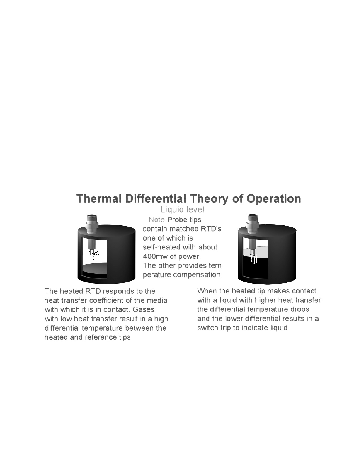
The Innova-Switch™ uses a thermal differential technique to sense changes in the heat
The Sierra Instruments’ sensor excitation method relies on constant current to the heated
DESCRIPTION
transfer characteristics of a media. Figures 1A and 1B show the outline of the InnovaSwitch™. The sensor consists of a pair of matched, Resistance Temperature Detectors
(RTD's) encased in twin 316L series stainless steel tubes. One RTD is self-heated using a
constant DC current. The other RTD is unheated to provide an accurate process
temperature reference. The thermal differential created between the heated and reference
RTD pair is a function of the density and/or velocity of the media with which the sensor is in
contact. Other physical properties may have a secondary effect as well. The differential is
greatest at a no flow (or dry) condition and decreases as the rate of flow increases (or as a
liquid quenches the sensor/wet condition).
and reference sensors. Thus power to the heated sensor is not constant but changes
linearly with temperature as the sensor resistance changes. Temperature compensation is
accomplished by using the amplified reference sensor voltage which also changes linearly
with temperature, as a dynamic reference. During calibration dry/no flow and wet/full flow
conditions are impressed across the trip point potentiometer. Since this reference is not
fixed but is set with respect to the reference sensor voltage, as temperature changes the trip
point potentiometer voltage changes with temperature exactly the same as that of the heated
sensor voltage with which it is being compared. Thus full temperature compensation is
achieved with non constant power.
1
Page 10
Sierra Instruments Innova-Switch™ Instruction Manual
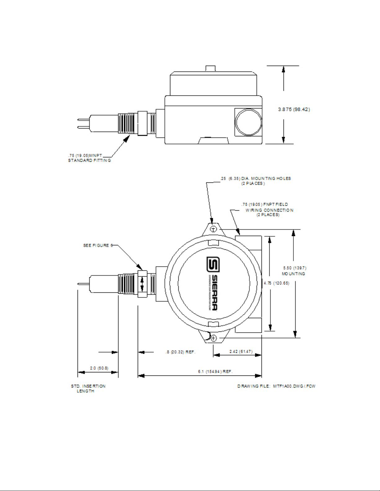
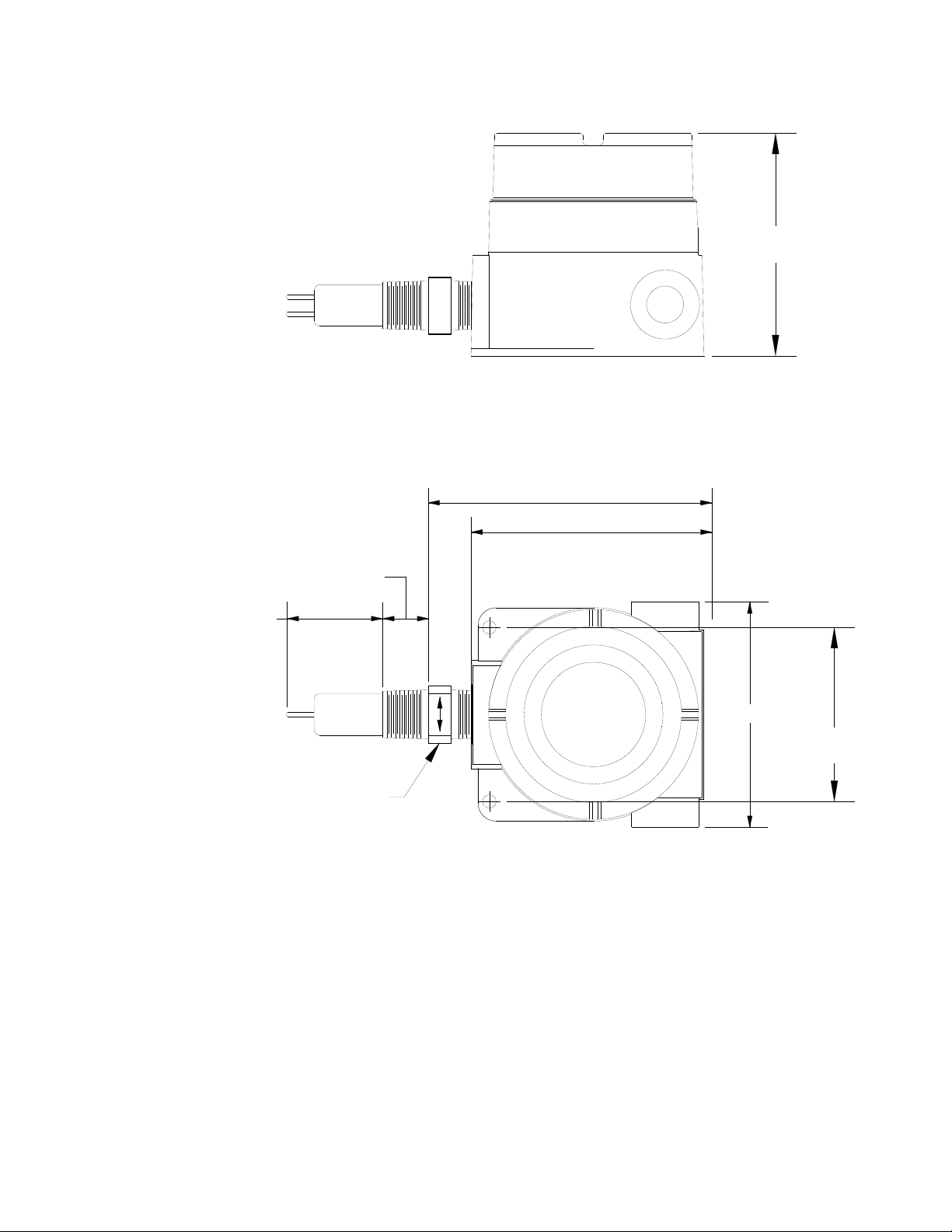
DIMENSIONS IN INCHES (MILLIMETERS)
FIGURE 1A INNOVA-SWITCH OUTLINE DIAGRAM STANDARD 2.0 INCH INSERTION
(KILLARK ENCLOSURE – NEMA 4-EExd 11B, T4) (MTF1A00.DWG/.FCW)
2
Page 11
Sierra Instruments Innova-Switch™ Instruction Manual
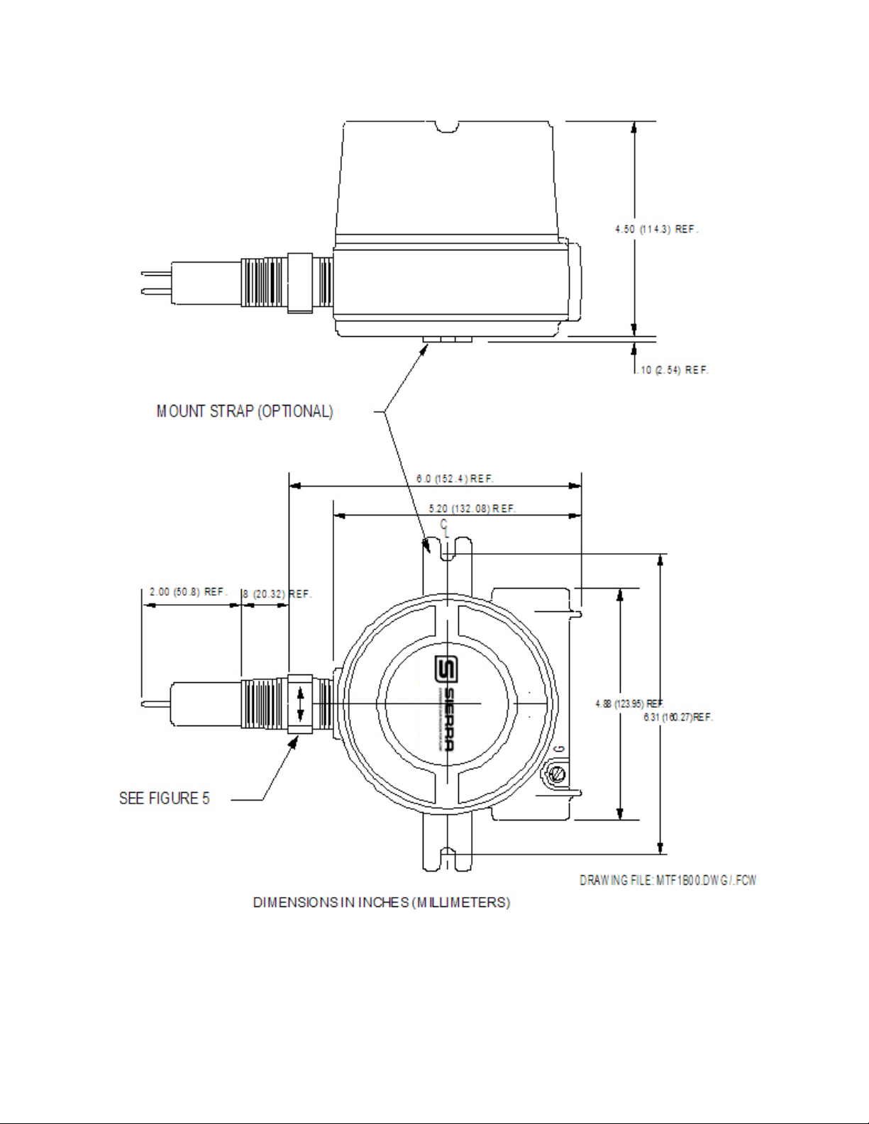
FIGURE 1B INNOVA-SWITCH 615 SERIES OUTLINE DIAGRAM STANDARD 2.0 INCH
INSERTION (AKRON ELECTRIC ENCLOSURE – NEMA 4X – EexdIIC, T4)
(MTF1B00.DWG/.FCW)
3
Page 12
Sierra Instruments Innova-Switch™ Instruction Manual
5.1 (129.54) REF.
6.0 (152.4) REF.
2.00 (50.8) REF.
DRAWING FILE: CIXI.DWG
5.20 (132) REF.
.8 (20.32) REF.
5.04 (128) REF.
3.88 (98.6) REF.
SEE FIGURE 5
DIMENSIONS IN INCHES (MILLIMETERS)
FIGURE 1C INNOVA-SWITCH 615 SERIES OUTLINE DIAGRAM STANDARD 2.0 INCH
INSERTION (CIXI ENCLOSURE – NEMA 4X)(CIXI.DWG)
4
Page 13
Sierra Instruments Innova-Switch™ Instruction Manual
2.1 LEVEL SWITCHING
The thermal differential created between the heated and reference unheated RTD pair is a
function of the liquid or gas medium with which the sensor is in contact.
The point level measurement application uses the heat transfer differences between two media
to detect liquid level. For example, air has a relatively poor heat transfer characteristic so the
heated sensor will become relatively hot. If the sensor is then immersed in water, the relatively
high heat transfer characteristics of water will cool the heated RTD surface causing a decrease
in the signal output.
This same rational applies for any two media in contact with the sensor. Each medium will have
its own characteristic heat transfer properties. As long as there is a reasonable difference in the
heat transfer properties between the two media, the Innova-Switch™ can discriminate between
them. Figure 2A shows the relative signal output of the Innova-Switch™ sensor to a range of
different media. The maximum difference in output occurs between vacuum and liquid metal.
However, a significant difference occurs between water and hydrocarbon liquids so the InnovaSwitch™ can be used to detect a water/hydrocarbon liquid-liquid interface. In general, the
interface between any two media with differing heat transfer properties can be detected.
5
Page 14

Sierra Instruments Innova-Switch™ Instruction Manual
SIGNAL
FIGURE 2A: RELATIVE CHANGE IN RESPONSE OF A HEATED RTD IMMERSED
IN VARIOUS MEDIA
VACUUM
DECREASING THERMAL DISPERSION OR HEAT TRANSFER
0
2.2 FLOW SWITCHING
Most mass flow monitoring techniques calculate mass indirectly by measuring volumetric flow
such as gallons per minute or cubic cm per second, then either measure density separately or
calculate it from temperature measurements of the fluid and, finally, combine density and
volumetric flow to obtain mass flow. The Sierra thermal-differential technique is one of two
methods that directly measure the mass flow. For ease of comparison most flow applications
are presented in terms of velocity which is independent of the flow cross sectional area (i.e. feet
per second (FPS)). The true mass flow equivalent would be FPS multiplied by density but for
simplicity FPS is used and density effects are ignored. This is normally not critical for flow
switching applications.
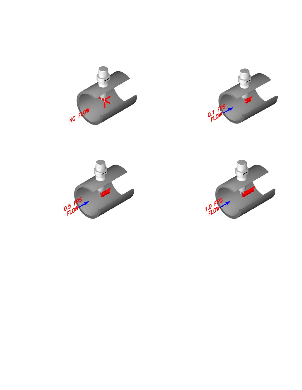
When the sensor is inserted into a liquid or gas the heated RTD is strongly affected by the
velocity of the medium. Flow past the heated RTD changes the heat transferred from the
surface of the sensor. This cooling effect reduces the temperature of the sensor. The
Innova-Switch™ compa re s th is c hange to a preset flow trip point to switch the output. Figure
2B shows the model 615 signal change vs. flow rate for air, light hydrocarbon liquids, and
water. The signal change vs velocity has the same general shape for all three media but the
change is larger for air and the sensitive range is different for each. For air and most
AIR
HYDROCARBON LIQUIDS
WATER
LIQUID METALS
MEDIA
DRAWING FILE: MTF2A0.DWG
6
Page 15
Sierra Instruments Innova-Switch™ Instruction Manual
gaseous media the range is 0.1 to 500 feet per second (FPS). For most liquid media the
range is 0.01 to 5 FPS (Hydrocarbons) and 0.01 to 2.5 FPS (water). Appendices in section
9.0 contain flow conversion information to facilitate conversion from various units and pipe
dimensions into flow velocity in feet per second.
Gas Or Liquid
Flow
Note: The fluid
velocity and heat
absorption ability
determine the
differential between
the tips. Their
For a no flow condition the thermal
differential between the two tips is
high because of relatively low heat
transfer.
When the lower differential matches
the customer select flow velocity trip
point (set point) the switch relay and
red LED are tripped.
combination
determines the
measurable
velocity. In water
velocities from 0.01
to 2.5 FPS are
measurable. In
Hydrocarbons
velocities from 0.01
to 5 FPS are
measurable,
whereas in air
velocities of 0.1 to
500 FPS can be
measured.
Flow across the tips decreases
the thermal differential because
of the higher heat transfer of
flowing fluids. This differential is
compared with the trip point.
When flow is above the trip point
the differential is smaller than at
the set point and the relay and
LED remain tripped.
7
Page 16

Sierra Instruments Innova-Switch™ Instruction Manual
FIGURE 2B INNOVA-SWITCH MODEL 615 FLOW RESPONSE FOR THREE MEDIA
8
Page 17

Sierra Instruments Innova-Switch™ Instruction Manual
Figure 3.A shows a block diagram of the Innova-Switch™.
Once the switch is set to respond to the minimum and maximum flow rates (or wet vs. dry
conditions), the trip point is set by adjusting the Trip Adjust Potentiometer. Solid state
electronics transform the flow (or wetting) induced temperature differential into a voltage that
is compared to a control voltage. Matching voltages cause actuation of a relay to indicate a
change in state (flow vs. no-flow or dry vs. wet).
TBA
1
H
2
HS
3
C
4
CS
5
RTN
6
RTNS
PROBE
FIGURE 3A: INNOVA-SWITCH SERIES BLOCK DIAGRAM
MODELS LS32CS/FS42CS, LS32CN/FS42CN, LS32NX/FS42NX,
AND LS32SK/FS42SK
(MTF3A00.DWG/.FCW)
VCC
SIGN AL PROCESSING ELECTRONICS
SENSORS EXCIT. CURRENTS RETURN
VCC
CURRENT SOURCES
TRIP P OINT
%
CALIBRATION
0 FLOW / DRY CAL.
TEST POINTS
1000
MA X.FLOW / WET CA L.
VCC
POWER SUPPLY
COMPARATOR
VCC
ENCLOSURE
VCC
RED
LED LIGHTS
GREEN
A
B
FAILSAFE LOG IC
RELAY DRIVER
RELAY
SAFETY GROUND
DRAWING FILE: MTF3A00.DW G/.FCW
10
9
8
N
POWER IN
7
H
6
C
5
NO
CONTA CT # 1
4
NC
3
C
2
NO
CONTACT 2
1
NC
9
Page 18

Sierra Instruments Innova-Switch™ Instruction Manual
Figure 3B shows a block diagram of the Innova-Switch™ with the addition of an EMC filter
required for the CE options (see section 7.0).
PROBE
TBA
1
H
2
HS
3
C
4
CS
5
RTN
6
RTNS
VCC
SIGNAL PROCESSING ELECTRONICS
SENSORS EXCIT. CURRENTS RETURN
FIGURE 3B: INNOVA-SWITCH MODELS WITH THE CE OPTION SWITCH BLOCK
DIAGRAM
(MTF3B00.DWG)
VCC
CURRENT SOURCES
TRIP POINT
%
CALIBRAT ION
R10
0 FLOW / DRY CAL.
MAX .F LOW / WE T CA L.
TEST POINT S
1000
R13
VCC
POWER SUPPLY
VCC
COMPARATOR
ENCLOSURE
RED
LED LIGHTS
GREEN
A
B
FAILSAFE LOGIC
RELAY DRIVER
EMC FILTER
CE
APPROVED
SWITCHES
10
N
VCC
RELAY
FILTERED POWER
9
H
8
N
7
H
6
C
5
NO
4
NC
3
C
2
NO
1
NC
TBB
POWER IN
CONTACT # 1
CONTACT 2
SAFETY G RO UND
DRAWING FILE: MTF3B00.DWG
10
Page 19

Sierra Instruments Innova-Switch™ Instruction Manual
The instrument enclosure at the top of unit contains the Innova-Switch™ electronics board which is
removable to access the terminal block and facilitate field wiring (see Figure 4.0). For applications
where the electronics must be located away from the sensors due to elevated process temperature,
accessibility, etc., another instrument head containing the electronics is remotely located (See option
RE-Remote Electronics section 3.2.2).
FIGURE 4 INNOVA-SWITCH™ ASSEMBLY
(MTF400.DWG/.FCW)
11
Page 20

Sierra Instruments Innova-Switch™ Instruction Manual
This page left blank intentionally.
12
Page 21

Sierra Instruments Innova-Switch™ Instruction Manual
3.0 INSTALLATION
3.1 MECHANICAL INSTALLATION
The standard Innova-Switch™ has a .75 inch (19.05mm) MNPT mount designed for easy
installation through a threaded port. Optional configurations include .5” (12.7mm) or 1.0”
(25.4mm) MNPT and flange mounts. Conduit is recommended for all wiring to the switch.
*IMPORTANT*
WHEN INSTALLING YOUR SIERRA INNOVA-SWITCHINTO A PIPE OR
VESSEL USE A 1 1/8 INCH (28.575mm) OPEN-END OR ADJUSTABLE
WRENCH TO TIGHTEN AT THE HEX FLATS OF THE MNPT OF A
STANDARD SWITCH. (IF YOU HAVE A NON-STANDARD SWITCH AN
ALTERNATE SIZE WRENCH MAY BE REQUIRED). DO NOT USE THE
INSTRUMENT HEAD TO TIGHTEN THE SWITCH TO THE MOUNTING
PORT. ROTATION OF THE INSTRUMENT HEAD WITH RESPECT TO THE
SENSOR BODY CAN CAUSE INTERNAL WIRING DAMAGE.
*IMPORTANT*
THE SWITCH BODY MUST BE ORIENTED TO HAVE THE TWIN SENSORS
PROPERLY ORIENTED. DUE TO THE PIPE THREAD MOUNTING, IT MAY
BE NECESSARY TO MAKE A TRIAL FIT, ADD OR REMOVE TEFLON
TAPE OR OTHER PIPE THREAD SEALANT, AND REINSTALL TO
ACHIEVE A SATISFACTORY SEAL WITH THE SENSORS PROPERLY
ORIENTED. PROPER ORIENTATION IS MARKED ON THE SWITCH BODY
FOR REFERENCE. SEE FIGURE 5.0 FOR DETAILS.
13
Page 22

Sierra Instruments Innova-Switch™ Instruction Manual
FIGURE 5: PROPER ORIENTATION OF THE SENSOR PROBE FOR LEVEL AND
FLOW APPLICATION IS INDICATED BY THE ARROW ON THE FLAT OF
THE MOUNTING FITTING. (MTF500.DWG/.FCW)
14
Page 23

Sierra Instruments Innova-Switch™ Instruction Manual
3.2 ELECTRICAL INSTALLATION
3.2.1 LOCAL ELECTRONICS (LE OPTION/STANDARD)
Remove the instrument enclosure lid by unscrewing in a counter clockwise direction.
Unscrew (CCW) the printed circuit board captive screws (See Figure 4.0 for locations).
Remove the PC board by grasping the transformer and pulling it straight out. Connect power
and alarm relay wiring to Terminal Block (TBB) as shown in Figure 6.0. Reinstall the InnovaSwitch™ electronics and tighten the captive screws.
NOTES:
INSTRUMEN T HEAD
WITH COVER
REMOVED
CAUTION
USE SUPPLY WI RES SUI TABLE
FOR 10 DEG. C ABOVE AMBIENT
NHCNONCN
-
+
POWER REL1-1 REL1-2
1
1
N
C
C
O
SAFETY GROUND
(NOTE 3)
TERMINAL BLOCK
LOCATIONS
TBB
WIRING CONNECTIONS (NOTE 4)
(NOTE 2)
POWER
N
H
NO CON
NO CON-+CNO
10987654
RELAY
NC
321
321
SAFETY GND
(DPDT)
CNONC
654
TBB
TBA
TBA
SENSOR
HOT
SENSOR
(NOTE 1)
COLD
TO SENSORS
DRAWING FILE: MTF600.DWG/.FCW
FIGURE 6.0 INNOVA-SWITCH™ LOCAL ELECTRONICS FIELD WIRING DIAGRAM
(MTF600FCW/.DWG)
1. Connections to sensors terminal block A (TBA) are factory installed and should
not be disconnected in the field. Note Jumpers 1-2, 3-4, and 5-6 must be in place
on TBA for proper operation of local electronics.
2. For 24 VDC operation (factory prepared), connect +positive to TBB7 and –negative
return to TBB8. For 110 VAC or 220 VAC connect hot to TBB7 and neutral to
TBB8.
3. Connect ground wire to ground screw located in or on the instrument enclosure.
4. Use supply wires suitable for 10 Degrees C above ambient.
*IMPORTANT*
A GROUND WIRE MUST BE ATTACHED TO THE GROUND SCREW
LOCATED INSIDE OR OUTSIDE OF THE INSTRUMENT ENCLOSURE FOR
PROPER OPERATION.
15
Page 24

Sierra Instruments Innova-Switch™ Instruction Manual
3.2.2 REMOTE ELECTRONICS (RE OPTION)
For the remote electronics option, mount the remote instrument head using two mounting
wings or bracket provided. Connect the switch wiring between the Innova-Switch™ remote
electronics as shown in Figure 7.0. Connect power wiring and alarm relay wiring to the
remote enclosure as shown in Figure 7.0. Upon completion of wiring reinstall the InnovaSwitch™ electronics and secure with the captive screws.
*IMPORTANT*
BE SURE TO APPLY THE PROPER VOLTAGE AS CONFIGURED AT THE
FACTORY. DO NOT APPLY 110 VAC TO 24 VDC VERSIONS OR 24 VDC
TO 110 VAC VERSIONS (LIKEWISE 220 VAC). NOTE THAT ALL
VOLTAGES ARE NOMINAL.
SPECIAL NOTICE
The electronic assemblies contained in the microtuf® models are configured for specific
voltages and have specific modifications to accommodate the various agency approvals.
When ordering spare electronics, replacements, or exchanges in the field please ensure
you identify the specific configuration you have by noting the boxes marked on the
transformer configuration tag and the serial number.
16
Page 25

Sierra Instruments Innova-Switch™ Instruction Manual
17
FIGURE 7A INNOVA-SWITCH ™ REMOTE ELECTRONICS OPTION FIELD WIRING
DIAGRAM (MTF701.DWG/.FCW)
Page 26

Sierra Instruments Innova-Switch™ Instruction Manual
18
FIGURE 7B INNOVA-SWITCH REMOTE ELECTRONICS CABLE TERMINATION
AND CONNECTIONS
Page 27

Sierra Instruments Innova-Switch™ Instruction Manual
S
3.2.3 CE OPTION FILTER BOARD CONNECTOR PLATE WIRING (CE OPTION)
Remove the instrument enclosure lid by unscrewing in a counter clockwise direction.
Unscrew (CCW) the printed circuit board captive screws (See Figure 4.0 for locations).
Remove the PC board by grasping the transformer and pulling it straight out. Connect power
and alarm relay wiring to Power Block as shown in Figure 6A. Reinstall the Innova-Switch™
electronics and tighten the captive screws.
FIGURE 6A INNOVA-SWITCH™ REMOTE ELECTRONICS FIELD WIRING DIAGRAM
(MTF6A00FCW/.DWG)
NOTES:
1. Connections to sensors terminal block A (TBA) are factory installed and should
not be disconnected in the field. Note Jumpers 1-2, 3-4, and 5-6 must be in place
on TBA for proper operation of local electronics.
2. For 24 VDC operation (factory prepared), connect +positive to TBB7 and –negative
return to TBB8. For 110 VAC or 220 VAC connect hot to TBB7 and neutral to
TBB8.
3. Connect ground wire to ground screw located in or on the instrument enclosure.
4. Use supply wires suitable for 10 Degree C above ambient.
TBB
TBA
SHIELDS
FLOATING AT
THIS END
HOT
SENSOR
GNDEARTH
CAUTI ON: Use s upply wires suitable
for 10°C above surrounding ambient.
NHCNONCN
-
+
POWER REL1-1 REL1-2
234
1
56
321
COLD
SENSOR
POWER
N
C
DM # 101654
O
C
SHIELDS CONNECTED
TO TERMINAL 5 AT
THIS END
3 TWISTED
SHIELDED PAIRS CABLE
654
REMOTE PROBE
RELAY CON T A CT S
REMOTE ELECTRONIC
FILTER CONN PLATE
(CE OPTION)
*IMPORTANT*
A GROUND WIRE MUST BE ATTACHED TO THE GROUND SCREW
LOCATED INSIDE OR OUTSIDE OF THE INSTRUMENT ENCLOSURE FOR
PROPER OPERATION.
19
Page 28

Sierra Instruments Innova-Switch™ Instruction Manual
This page left blank intentionally.
20
Page 29

Sierra Instruments Innova-Switch™ Instruction Manual
4.0 OPERATION AND CALIBRATION OF THE INNOVA- SWITCH™ MODEL 615 FOR
FLOW
4.1 Pre-Operational Check
With the switch installed and process conditions at no-flow, the following procedure can be
used to verify preliminary operation.
4.1.1 Remove the instrument enclosure cover by turning counter clockwise (ccw) to expose the
Innova-Switch™ electronics.
4.1.2 Turn on power at its source.
4.1.3 Observe that either the red or green LED comes on.
4.1.4 If neither lamp illuminates refer to the trouble shooting Section, 6.2.
4.2 L.E.D. and Relay Status Logic (Fail-safe)
4.2.1 The L.E.D.s (Red; Green) are an indication of the sensors status (ie. flow below the setpoint
or flow above the set point) and are not affected by the position of the failsafe jumper J-2.
The failsafe jumper J-2 changes the relay activation status allowing the user to select the
failsafe power off condition most appropriate to the application. Refer to the tables below
that show the logic conditions between the sensors, L.E.D. lights, relay coil and contacts for
each position of the failsafe jumper J-2.
4.2.2 Normal Operation (as set at factory)
The switch comes configured from the factory with the following operation with the J-2
jumper in the B(2-3) position. (Refer to Figure 8.0.)
RELAY
RED GREEN RELAY CONTACT
SENSOR STATUS LED LED COIL STATUS STATUS
o NC
No Flow or Flow Below Set Point ON OFF Activated
o NO
o NC
Flow or Flow Above Set Point OFF ON Deactivated
o NO
APPLICATIONS
21
Page 30

Sierra Instruments Innova-Switch™ Instruction Manual
FIGURE 8.0 INNOVA-SWITCH™ ELECTRONICS
(MTF800.FCW/.DWG)
4.2.3 Alternate Operation (Field Selectable)
The relay logic may be reversed by moving the J-2 jumper to position A(1-2). (Refer to
Figure 8.0.)
RED GREEN RELAY CONTACT
SENSOR STATUS LED LED COIL STATUS STATUS
o NC
No Flow or Flow Below Set Point ON OFF Deactivated
o NC
Flow or Flow Above Set Point OFF ON Activated
o NO
RELAY
o NO
22
Page 31

Sierra Instruments Innova-Switch™ Instruction Manual
010
SIGNAL (mV)
LIQUIDS
GASES
LED LIGHTS
FIGURE 9.0 INNOVA-SWITCH MODEL 615 FLOW SWITCH
CALIBRATION REFERENCE DRAWING
(MTF900.DWG.FCW)
PROBE FLOW RESPONSE FOR THREE MEDIA AND
CALIBRATION SETTINGS FOR EACH
AIR
HYDROCARBONS
WATER
0
0.001
0.10
RED
GREEN
GND
0.01
1.0
RED
FUSE
H2
H1
N2
L1
N1
U3
Q1
U1
0.10
10.0
VELOCITY (FPS)
FAILSAFE JUMPER (J2)
J2
AB
GREEN
RELAY
Q6
T1
U4
<----->
TP1
U2
TP4
R13
J1
50
R10
0
100
TP3
TP2
1.0
100.0
R15
DRAWING FILE: MTF900.DWG/.FCW
FS42CS
FS42CE
FS42NX
FS42SK
10
1000
R10
(ZERO ADJ.)
R15
(TRIP POINT ADJ.)
TRIP POI NT POT. (R15) SCALE
% SPAN
100
50
0
R13
(SPAN ADJ.)
SPAN
TRIP POINT
0
% SPAN
100
50
LIQUIDS
GASES
NORMALIZED RESPONSE AFTER CALIBRATION
0
0.001
0.10
0.01
1.0
0.10
10.0
VELOCITY (FPS)
1.0
100.0
1
23
Page 32

Sierra Instruments Innova-Switch™ Instruction Manual
4.3 CALIBRATION – FLOW
**IMPORTANT**
FOR OPTIMUM OPERATION, CALIBRATION MUST BE ACCOMPLISHED AT
ACTUAL PROCESS TEMPERATURE AND PRESSURE CONDITIONS IN GASES
AND AT ACTUAL PROCESS TEMPERATURE CONDITIONS IN LIQUIDS.
See Figures 8.0 and 9.0 for location of potentiometers and LEDS on electronics PCB.
4.3.1 CALIBRATION PROCEDURE FOR FLOW SWITCHES
1. Remove the instrument enclosure lid by turning ccw.
2. Apply power to FS4200. Allow 10 minute warm-up.
3. Ensure that the pipeline is filled with fluid and at no or minimum flow.
4. Set the trip adjust pot to zero fully counterclockwise (fully ccw).
5. Adjust the zero adjust pot so that the Red LED just does illuminate. This is a 25 turn pot. If the
Green LED is on, turn the pot ccw. If the Red LED is on, turn the pot clockwise (cw).
6. Toggle the zero adjust pot back and forth until the switching point is well defined. Leave the Red
LED illuminated.
7. Adjust the liquid or gas flow to maximum velocity. Insure that the flow is homogenous, constant
and free of bubbles if a liquid.
The flow rate (maximum) should be at least 5 fps (Hydrocarbons), 2.5 fps (water), or 500 fps
(gas/air) if possible for best calibration. It is possible to achieve a 5 fps set point in water if a
span of 7 fps can be achieved.
TO ENSURE ACCURATE CALIBRATION AND AVOID SET POINT DRIFT, IT IS
IMPERATIVE THAT A MINIMUM OF 10 MINUTE WAIT BE OBSERVED AFTER POWER IS
APPLIED TO ALLOW THE SENSOR TO WARM-UP TO THE AMBIENT FLUID
TEMPERATURE.
LIKEWISE, WHEN ADJUSTING THE ZERO, SPAN, AND SET POINT POTS, A
MINIMUM OF 30 SECONDS SHOULD BE OBSERVED TO ALLOW FOR STABILIZATION
OF TEMPERATURE.
8. Set the trip adjust pot to 100 (fully cw).
9. Adjust the span adjust pot so that the Green LED just does illuminate. This is a 25 turn pot.
If the Green LED is on, turn the pot cw. If the Red LED is on, turn the pot ccw.
10. Toggle the span adjust pot back and forth until the switching point is well defined. Leave the
Green LED illuminated.
11. If the switch is to be used for flow - no flow, set the trip adjust pot to 50 and go to step 14. (Note:
This adjustment can be set for tripping points between 10% and 90% of the span from no flow to
max flow).
12. A more exact flow rate setting may be made by establishing the flow at the desired rate with a
separate flow meter and proceeding to step 13, to establish the trip point.
13. Adjust the trip adjust pot to obtain a trip as exhibited by an LED illumination. If a trip on
**NOTE**
24
Page 33

Sierra Instruments Innova-Switch™ Instruction Manual
decreasing flow is desired set for Red LED illumination. If a trip on increasing flow is desired set
for Green LED illumination.
14. Verify that the switch will reset by returning the actual product flow to the maximum or minimum
flow rates.
5.0 OPERATION AND CALIBRATION OF THE INNOVA-SWITCH™ 615 SERIES SWITCH
FOR POINT LEVEL
5.1 PRE-OPERATIONAL CHECK
The switch is installed and the product level is below sensor level (dry), the following
procedure can be used to verify preliminary operation.
1. Remove the instrument enclosure cover by turning counter clockwise to expose the
LS3200 Switch electronics.
2. Turn on power at its source.
3. Observe that either the red or green LED comes on.
4. If neither lamp illuminates refer to the trouble shooting Section, 6.2.
5.2 L.E.D. AND RELAY STATUS LOGIC (FAIL-SAFE)
5.2.1 The L.E.D.s (Red and Green) are an indication of the sensors status (ie. dry or wet) and are
not affected by the position of the fail-safe jumper J-2. The fail-safe jumper J-2 changes the
relay activation status allowing the user to select the fail-safe power off condition most
appropriate to the application. Refer to the tables below that show the logic conditions
between the sensors, L.E.D. lights, relay coil and contacts for each position of the fail-safe
jumper J-2.
5.2.2 NORMAL OPERATION (AS SET AT FACTORY)
The switch comes configured from the factory with the following operation with the J-2 jumper
in the B (2-3) position. (Refer to Figure 8.0.)
RELAY
RED GREEN RELAY CONTACT
SENSOR STATUS LED LED COIL STATUS STATUS
Dry, or Lower Thermal o NC
Dispersion Fluid ON OFF Activated
(ie. hydrocarbons) o NO
Wet, or Higher Thermal o NC
Dispersion Fluid OFF ON Deactivated
(ie. water) o NO
APPLICATIONS
25
Page 34

Sierra Instruments Innova-Switch™ Instruction Manual
5.2.3 ALTERNATE OPERATION (FIELD SELECTABLE)
The relay logic may be reversed by moving the J-2 jumper to position A(1-2). (Refer to
Figure 8.0.)
RELAY
RED GREEN RELAY CONTACT
SENSOR STATUS LED LED COIL STATUS STATUS
o NC
Dry, or Lower Thermal ON OFF Deactivated
Dispersion Fluid o NO
(ie. hydrocarbons)
o NC
Wet, or Higher Thermal OFF ON Activated
Dispersion Fluid o NO
(ie. water)
FIGURE 8.0 INNOVA-SWITCH™ ELECTRONICS
(MTF800.FCW/.DWG)
26
Page 35

Sierra Instruments Innova-Switch™ Instruction Manual
5.3 CALIBRATION – LEVEL
**IMPORTANT**
FOR OPTIMUM OPERATION CALIBRATION MUST BE ACCOMPLISHED AT
ACTUAL PROCESS TEMPERATURE CONDITIONS.
SENSOR
SIGNAL (mV)
DRAWING FILE: MTF1000.DWG/.fcw
FIGURE 10.0 INNOVA-SWITCH MODEL 615 POINT LEVEL SWITCH CALIBRATION
REFERENCE DRAWING
(MTF1000.DWG/.FCW)
DECREASING THERMAL DISPERSION
COVER GAS
VACUUM
LED LIGHTS
OR AIR
ZERO ADJUSTMENT
GREEN
R
HYDROCARBON LI QUIDS
0 100
(R10)
TRIP POINT
E
D
RED
FUSE
H2
H1
N2
L1
N1
GND
U3
Q1
U1
50
LS32CS
LS32CN
LS32NX
LS32SK
LIQUID METALS
TRIP POINT POT SCALE
SPAN ADJUSTMENT
(R13)
FAILSAFE JUMPER (J2)
J2
AB
GREEN
RELAY
Q6
TP1
T1
R10
TP3
U4
<----->
WATER
U2
TP4
R13
J1
50
0
TP2
FLUIDS
0.0
R15
100
27
Page 36

Sierra Instruments Innova-Switch™ Instruction Manual
5.3 CALIBRATION - LEVEL
Using Figure 10.0 as a location guide adjust the system as follows:
1. Remove the instrument enclosure lid by turning ccw.
2. Apply power to the unit. Allow 10 minute warm-up.
3. For optimum calibration results, wet sensor and drain but do not dry.
4. Ensure that the tank liquid level is below the probe sensor tips.
5. Set the trip adjust pot to zero, fully counterclockwise (fully ccw).
TO ENSURE ACCURATE CALIBRATION AND AVOID SET POINT DRIFT, IT IS
IMPERATIVE THAT A MINIMUM OF 10 MINUTE WAIT BE OBSERVED AFTER POWER IS
APPLIED TO ALLOW THE SENSOR TO WARM-UP TO THE AMBIENT FLUID
TEMPERATURE.
LIKEWISE, WHEN ADJUSTING THE ZERO, SPAN, AND SET POINT POTS, A
MINIMUM OF 30 SECONDS SHOULD BE OBSERVED TO ALLOW FOR STABILIZATION
OF TEMPERATURE.
6. Adjust the zero adjust pot so that the Red LED just does illuminate. This is a 25 turn
pot. If the green LED is on, turn the pot counterclockwise (ccw). If red LED is on, turn
the pot clockwise (cw).
7. Toggle the zero adjust pot back and forth until the switching point is well defined. Leave
the Red LED illuminated.
8. Raise the level of the liquid to be detected until the probe/sensor tips are submerged
and wet (covered).
9. Set the trip adjust pot to 100 (fully cw).
10. Adjust the span adjust pot so that the Green LED just does illuminate. This is a 25 turn
pot. If the Green LED is on, turn the pot cw. If the Red LED is on, turn the pot ccw.
11. Toggle the span adjust pot back and forth until the switching point is well defined. Leave
the green LED illuminated.
12. Adjust the trip adjust pot to 80 and the calibration is complete. Setting this pot to 80
gives an approximate equal trip time from wet to dry and from dry to wet. Setting this pot
closer to zero will speed up dry to wet trip time and slow down wet to dry trip time.
Setting this pot closer to 100 will slow down the dry to wet trip time and speed up wet to
dry trip time.
28
Page 37

Sierra Instruments Innova-Switch™ Instruction Manual
6.0 MAINTENANCE AND TROUBLE SHOOTING
6.1 CLEANING
The switch can be cleaned by soaking, spraying solvents or detergent-and-water onto the
sensor tubes, or by ultrasonic cleaning.
Lime deposits can be safely removed by soaking in 20% hydrochloric acid. Warming to
150°F is permissible to speed this process. The acid must be thoroughly rinsed off once
cleaned.
For unusual cleaning problems, call Sierra and determine the exact materials of construction
and chemical compatibility before using strong acids or unusual cleansers.
**IMPORTANT**
DO NOT SANDBLAST OR ABRASIVE CLEAN THE SENSING PROBES.
THE SENSING PROBES COULD BE DAMAGED BY ABRASIVES.
6.2 Trouble Shooting
6.2.1 Power and Continuity Verification
1. Turn power off to the Innova-Switch™.
2. Remove the instrument enclosure cover (ccw).
3. Loosen the two PC captive screws (see Figure 4.0 for location).
4. Unplug the PC board from the instrument enclosure by pulling straight out on the
transformer.
5. Reapply power and verify correct voltage at pins 7 (positive for DC) and 8 (negative for
DC) of TBB (see Figures 6.0 or 7.0).
6. If voltage is correct, verify the fuse (F1) on the PC board is not blown (See Figure 8.0). If
fuse is not blown proceed to 6.2.2.
7. If fuse is blown replace with appropriate value (See 7.0 Specification).
29
Page 38

Sierra Instruments Innova-Switch™ Instruction Manual
6.2.2 SENSOR/ELECTRONICS FUNCTIONALITY VERIFICATION
1. Turn power off to Innova-Switch™.
2. Allow a 5 minute cool down.
3. Measure the resistance of each RTD at pins 1 and 6 of TBA (see Figure 6.0 or 7.0) for
the hot RTD and pins 3 and 5 of TBA for the cold RTD. These resistances should be
110 ± 10 ohms (with sensors at approximately 70°F) and within 5% of each other in
value.
4. Measure the insulation resistance between pin 1 of TBA and the case of the InnovaSwitch™. It should be greater than 20 megohms.
5. If the Innova-Switch™ sensor assembly resistances are not as specified above, the
switch sensor assembly must be replaced.
5. If the Innova-Switch™ sensor assembly resistances are as specified, the InnovaSwitch™ PC electronic board must be replaced.
6.2.3 SET POINT DRIFT
TO ENSURE ACCURATE CALIBRATION AND AVOID SET POINT DRIFT, IT IS
IMPERATIVE THAT A MINIMUM OF 10 MINUTE WAIT BE OBSERVED AFTER POWER IS
APPLIED TO ALLOW THE SENSOR TO WARM-UP TO THE AMBIENT FLUID
TEMPERATURE.
LIKEWISE, WHEN ADJUSTING THE ZERO, SPAN, AND SET POINT POTS, A
MINIMUM OF 30 SECONDS SHOULD BE OBSERVED TO ALLOW FOR STABILIZATION
OF TEMPERATURE.
SPECIAL NOTICE
The electronic assemblies contained in the Innova-Switch™ models are configured
for specific voltages and have specific modifications to accommodate the various
agency approvals. When ordering spare electronics, replacements, or exchanges
in the field please ensure you identify the specific configuration you have by noting
the boxes marked on the transformer configuration tag.
30
Page 39

Sierra Instruments Innova-Switch™ Instruction Manual
7.0 SPECIFICATIONS
TYPE: Thermal Differential-Dual RTD Sensors
PROCESS CONNECTIONS: 0.75” (19.05mm) MNPT Standard, 0.5"(12.7mm), 1" (25.4mm)
MNPT, and various flanges optional.
INSERTION LENGTH: Two inch (50.8mm) Standard, (shorter 0.5 inch (12.7mm) and
longer to 120 inch (3048mm) optional).
CONSTRUCTION MATERIALS: Wetted parts are 316L SS welded construction (alternate
materials for corrosive environments available as options.
Consult factory.)
AGENCY INSTRUMENT RATINGS: CSA Explosion Proof: (CS series) T4A
Class I, Group B, C, and D
Class II, Group E, F, and G
CENELEC/Explosion Proof (CN Series):
EEx d IIC T4(Akron Electric Enclosure)
EEx d IIB T4(Killark Enclosure)
CE: EMC Directive: 89/336/EEC (CE Option)
OPERATING TEMPERATURE: Process: -70°C to + 200°C (-100°F to +390°F) standard
(to + 600°C (+1000°F) optional
Electronics: -40°C to +60°C (-40°F to +140°F)
PRESSURE RATED: To 3000 psig (20.4 MPa)
RANGE Gaseous Mass Flow: 0.1 to 500 fps
Liquid Mass Flow: 0.01 to 5 fps (Hydrocarbons) 2.5 fps (water)
REPEATABILITY: ± 1% of Set Point or ± 1/32 inch (±.8mm)
TIME RESPONSE: 0.5 to 10 seconds no-flow (dry) to flow (wet) and 2 to 60
seconds flow (wet) to no-flow (dry) (application dependent)
INPUT POWER: 110 Vac, 50/60HZ standard. (220 Vac, 50/60HZ, 24 Vdc, or 24
Vac optional); 3.1w. maximum.
SIERRA PART NO.
FUSE REQUIREMENTS (F1): CSA/FM
CENELEC
110 Vac: 1/4 amp 101603 101605
220 Vac: 1/4 amp 101603 101605
24 Vdc: 1/4 amp 101603 101605
OUTPUT: 5A, 250 VAC, DPDT Standard (Optional 10A, 250 Vac SPDT)
5A 30 VDC
STABILITY: Temperature compensated over entire range.
31
Page 40

Sierra Instruments Innova-Switch™ Instruction Manual
8.0 WARRANTY AND SERVICE
8.1 Warranty
Sierra Instruments, Inc. warranties Innova-Switches for a period of two years from the date of
shipment and will repair or replace this product in the event of a defect in materials or
workmanship. To have a product repaired, it should be returned at customer's expense, after
obtaining return authorization as described in Section 8.2, to a repair facility designated by
Sierra and, after repair, Sierra will prepay transportation to return the product to the
customer. This limited warranty only covers failures due to defects in materials or
workmanship which occur during normal use.
LIMITS AND EXCLUSIONS
SIERRA INSTRUMETNS SHALL NOT BE LIABLE FOR INCIDENTAL OR
CONSEQUENTIAL DAMAGES (INCLUDING, BUT NOT LIMITED TO,
LOSS OF USE, LOSS OF SALES, OR INCONVENIENCE) RESULTING
FROM THE USE OF THESE PRODUCTS, OR ARISING OUT OF ANY
BREACH OF THIS WARRANTY. EXCEPT AS SET FORTH ABOVE,
THERE ARE NO EXPRESS OR IMPLIED WARRANTIES OR WARRANTIES
OF MERCHANTABILITY OR FITNESS FOR A PARTICULAR PURPOSE.
8.2 SERVICE
To receive prompt service call Sierra’s Customer Service Dept. (865) 483-1569 or toll free 1-
800-922-0083. A representative will assist you in determining if the unit must be returned to
the factory. A Return Authorization Number (RAN) will be given and should clearly mark the
outside of the returning package. Prior to calling, be sure to have the model number and
serial number information for quick identification and service response.
32
Page 41

Sierra Instruments Innova-Switch™ Instruction Manual
9.0 APPENDIX
9.1 VOLUME FLOW CONVERSION CHART
Convert known units to cubic feet per second (CFPS) or gallons per minute (GPM)
for use with Chart A.2
TO CONVERT FROM TO MULTIPLY BY
Gallons Per Minute (GPM) Cubic Feet Per 2.228 E-03
Per Second (CFPS)
Gallons Per Day (GPD) CFPS 1.547 E-06
Barrels Per Day (BPD) CFPS 6.531 E-5
Cubic Ft. Per Minute (CFPM) CFPS 1.667 E-02
Cubic In. Per Minute (CIPM) CFPS 9.645 E-06
Milliliters Per Minute (MLPM) CFPS 5.886 E-07
Milliliters Per Second (MLPS) CFPS 3.531 E-05
Milliliters Per Hour (MLPH) CPFS 9.810 E-09
Liters Per Day (LPD) CPFS 4.087 E-07
Gallons Per Day (GPD) GPM 6.944 E-04
Barrels Per Day (BPD) GPM 2.931 E-02
Cubic Ft. Per Second (CFPS) GPM 4.488 E+02
Cubic Ft. Per Minute (CFPM) GPM 7.481
Cubic In. Per Minute (CIPM) GPM 4.329 E-03
Milliliters Per Minute (MLPM) GPM 2.642 E-04
Milliliters Per Second (MLPS) GPM 4.403 E-06
Milliliters Per Hour (MLPH) GPM 1.585 E-02
Liters Per Day (LPD) GPM 1.835 E-04
33
Page 42

Sierra Instruments Innova-Switch™ Instruction Manual
N
9.2 FLOW CONVERSION CHART
MILLILITERS
10.0
CC/MIN
PER MINUTE
8.0
9.0
6.0
7.0
5.0
4.0
3.0
2.0
.61
.50
.40
.30
.20
.10
.090
.080
CU IN/MIN
PER MINUTE
CUBIC INCHES
.00008
.0003
.00034
.00020
.00010
.00009
.00007
.00006
.00005
-7
CUBIC FEET
PER MINUTE
CU FT/MIN
-7
-7
-7
-7
-7
-7
-7
-7
56.8X10
50.0X10
40.0X10
30.0X10
20.0X10
10.0X10
9.0X10
8.0X10
7.0X10
CUBIC FEET
PER SECOND
CU FT/SEC
.0905
.08
.06
.07
.05
.04
.03
.02
BARRELLS
PER DAY
BPD
3.82
3.0
2.0
.90
.80
.70
1.00
.60
GALLONS
PER DAY
GPD
1.0
.070
.061
.00004
.000034
-7
5.68X10
.010
.00905
.50
.382
.00264
.0020
.00090
.0010
.00080
.00070
.00060
.00050
.00040
.00030
.000264
FLOW CONVERSION CHART
GALLONS
GPM
PER MINUTE
.050
3.0
4.00
.040
100
.030
2.00
908070
3.00
2.0
.020
1.44
60
.0167
1.0
THIS LINE CHART PROVIDES AN EASY METHOD FOR CONVERTING UNITS OF VOLUME FLOW. SIMPLY DRAW A LINE PERPENDICULAR TO THE
SCALE LINES THROUGH A VALUE OF FLOW AND READ THE EQUIVALENT VALUE ON ANY OF THE OTHER SCALES.
9.00
.100
6.0
8.00
.090
5.0
7.00
300
.080
14.4
LPD
LITERS
PER DAY
600
CC/HR
PER HOUR
MILLILITERS
.167
MILLILITERS
PER SECOND
CC/SEC
10.0
ILLILITERS
PER MINUTE
CC/MI
500
9.0
8.0
10.00
400
7.0
.070
4.0
6.00
5.00
200
.060
34
Page 43

Sierra Instruments Innova-Switch™ Instruction Manual
9.3 FLOW OF WATER THROUGH SCHEDULE 40 STEEL PIPE
35
Page 44

Sierra Instruments Innova-Switch™ Instruction Manual
10.0 OPTIONS
10.1 LIVETAP (LT)
36
Page 45

Sierra Instruments Innova-Switch™ Instruction Manual
10.2 VARIABLE INSERTION (VI)
37
Page 46

Sierra Instruments Innova-Switch™ Instruction Manual
10.3 SANITARY (3A1)
Innova-Switch™ Sanitary
Sanitary Switch Operating Instructions
Installation
Sierra’s Sanitary Switch Option is to be installed
using industry standard piping practices. Make sure
that you have selected the proper gasket and clamp
designed for your pressure, temperature and process
fluid.
*Shown above with optional Sanitary Tee
38
Page 47

Sierra Instruments Innova-Switch™ Instruction Manual
10.4 LOW FLOW (LF)
Innova-Switch Low Flow Sensor
• Developed for low flow gas and liquid applications where reliability and durability are mandatory
• Very low internal volume so that sample times are very short and sample system response
remains quick
• All Welded Stainless Steel Construction
• Standard operating temperature range of -100°F to 390°F
• ¼ inch FNPT process ports that can easily be adapted to tubing by using standard fittings
39
 Loading...