

Sierra 241 Series,240-V,240 Series,240-VT,240-VTP,240-LP,241-V,241-VT,241-VTP,241-LP Instruction Manual

Sierra 240/241Series Instruction Manual Table of Contents
240/241 Series
Vortex Volumetric and Mass Flow Meters
Models: 240-V, VT, VTP, LP / 241-V, VT, VTP, LP, Cryogenic
Instruction Manual
Document Number IM-240
Revision: M.8/19
IM-240 0-1

Table of Contents Sierra 240/241Series Instruction Manual
GLOBAL SUPPORT LOCATIONS: WE ARE HERE TO HELP!
CORPORATE HEADQUARTERS
5 Harris Court, Building L Monterey, CA 93940
Phone (831) 373-0200 (800) 866-0200 Fax (831) 373-4402
www.sierrainstruments.com
EUROPE HEADQUARTERS
Bijlmansweid 2 1934RE Egmond aan den Hoef
The Netherlands
Phone +31 72 5071400 Fax +31 72 5071401
ASIA HEADQUARTERS
Second Floor Building 5
Senpu Industrial park
25 Hangdu Road Hangtou Town
Pu Dong New District
Shanghai, P.R. China Post Code 201316
Phone: 8621 5879 8521 Fax: 8621 5879 8586
IMPORTANT CUSTOMER NOTICE: OXYGEN SERVICE
Unless you have specifically ordered Sierra’s optional O2 cleaning, this flow meter may not
be fit for oxygen service. Sierra Instruments, Inc., is not liable for any damage or personal injury, whatsoever, resulting from the use of Sierra Instruments standard mass flow meters for
oxygen gas. You are responsible for cleaning the mass flow meter to the degree required for
your oxygen flow application. However, some models can only be properly cleaned during
the manufacturing process.
© COPYRIGHT SIERRA INSTRUMENTS 2016
No part of this publication may be copied or distributed, transmitted, transcribed, stored in
a retrieval system, or translated into any human or computer language, in any form or by
any means, electronic, mechanical, manual, or otherwise, or disclosed to third parties
without the express written permission of Sierra Instruments. The information contained in
this manual is subject to change without notice.
TRADEMARKS
InnovaFlo® and InnovaMass® are trademarks of Sierra Instruments, Inc. Other product
and company names listed in this manual are trademarks or trade names of their respective manufacturers.
0-2 IM-240

Sierra 240/241Series Instruction Manual Table of Contents
Table of Contents
Chapter 1 Introduction
InnovaMassVortex Mass Flow Meters ................................................ 1-1
Using this Manual ......................................................................... 1-1
Note and Safety Information ......................................................... 1-2
Receipt of System Components .................................................... 1-2
Technical Assistance ..................................................................... 1-2
How the InnovaMass Vortex Meter Operates ..................................... 1-3
Velocity Measurement .................................................................. 1-3
Vortex Shedding Frequency .......................................................... 1-4
Vortex Frequency Sensing ............................................................ 1-4
Flow Velocity Range ..................................................................... 1-5
Temperature Measurement ............................................................ 1-6
Pressure Measurement ................................................................... 1-6
Flow Meter Configurations .................................................................. 1-7
Multivariable Options ................................................................... 1-7
Line Size / Process Conditions / Materials .................................... 1-8
Flow Meter Electronics ................................................................. 1-8
Chapter 2 Installation
Installation Overview ........................................................................... 2-1
Flow Meter Installation Requirements .......................................... 2-1
Unobstructed Flow Requirements ................................................. 2-2
240 In-Line Flow Meter Installation .................................................... 2-3
Wafer-Style Flow Meter Installation ............................................. 2-4
Flange-Style Flow Meter Installation ............................................ 2-5
241 Insertion Flow Meter Installation ................................................. 2-6
Cold Tap Guidelines...................................................................... 2-7
Hot Tap Guidelines ....................................................................... 2-8
Flow Meter Insertion ......................................................................... 2-10
Installing Meters with a Compression Connection ..................... 2-11
Installing Meters with a Packing Gland Connection ................... 2-13
Installing Meters (Packing Gland), No Insertion Tool ................ 2-16
Adjusting Meter Orientation .............................................................. 2-18
Display/Keypad Adjustment ....................................................... 2-18
Enclosure Adjustment ................................................................. 2-19
Loop Power Flow Meter Wiring Connections ................................... 2-20
Input Power Connections ............................................................ 2-20
4-20 mA Output Connections ..................................................... 2-21
Pulse Output Connections ........................................................... 2-22
Frequency Output Connections ................................................... 2-23
Optional Backlight Connections ................................................. 2-23
Remote Electronics Wiring ......................................................... 2-24
High Power Flow Meter Wiring Connections ................................... 2-26
Input Power Connections ............................................................ 2-26
4-20 mA Output Connections ..................................................... 2-28
Frequency Output Connections ................................................... 2-29
IM-240 0-3

Table of Contents Sierra 240/241Series Instruction Manual
Pulse Output Connections ........................................................... 2-30
Alarm Output Connections .......................................................... 2-32
Remote Electronics Wiring ......................................................... 2-33
Optional Input Electronics Wiring .............................................. 2-34
Optional Energy EMS RTD Input Wiring .................................. 2-34
Optional External 4-20 mA Input Wiring ................................... 2-35
Optional Contact Closure Input Wiring ...................................... 2-36
Chapter 3 Operating Instructions
Flow Meter Display/Keypad ................................................................ 3-1
Start Up ................................................................................................ 3-2
Using the Setup Menus ........................................................................ 3-4
Programming the Flow Meter ....................................................... 3-5
Output Menu ................................................................................. 3-6
Display Menu ................................................................................ 3-8
Alarms Menu ................................................................................. 3-9
Totalizer #1 Menu ....................................................................... 3-10
Totalizer #2 Menu ....................................................................... 3-11
Energy Menu ....................................................................... 3-12
Fluid Menu .................................................................................. 3-13
Units Menu .................................................................................. 3-14
Time and Date Menu ................................................................... 3-15
Diagnostics Menu ........................................................................ 3-16
Calibration Menu ......................................................................... 3-17
Password Menu ........................................................................... 3-18
Chapter 4 Serial Communications
HART Communications ...................................................................... 4-1
Wiring ........................................................................................... 4-2
HART Commands with the DD Menu .......................................... 4-3
HART Commands with Generic DD Menu .................................. 4-4
MODBUS Communications ................................................................ 4-7
Wiring ........................................................................................... 4-7
Menu Items .................................................................................... 4-8
Register Definitions ..................................................................... 4-10
BACNET MSTP Communications .................................................... 4-21
BACNET MSTP Description ...................................................... 4-21
Baud Rates on the MS/TP Bus .................................................... 4-21
Supported BACnet Objects ......................................................... 4-22
ANNEX - BACnet Protocol Implementation Conformance
Statement ..................................................................................... 4-28
Acronyms and Definitions .......................................................... 4-34
Chapter 5 Troubleshooting and Repair
Hidden Diagnostics Menus .................................................................. 5-1
Level One Hidden Diagnostics Values ......................................... 5-3
Level Two Hidden Diagnostics Values ......................................... 5-4
Analog Output Calibration .................................................................. 5-7
Troubleshooting the Flow Meter ......................................................... 5-8
0-4 IM-240

Sierra 240/241Series Instruction Manual Table of Contents
First Check Items ................................................................................. 5-8
Record Values ...................................................................................... 5-8
Determine the Fault ............................................................................. 5-9
Symptom: Output at no Flow ........................................................ 5-9
Symptom: Erratic Output .............................................................. 5-9
Symptom: No Output .................................................................. 5-11
Symptom: Meter Displays Temperature Fault ............................ 5-12
Symptom: Meter Displays Pressure Fault ................................... 5-13
Electronics Assembly Replacement ................................................... 5-14
Pressure Sensor Replacement (Series 240 Only) .............................. 5-15
Returning Equipment to the Factory .................................................. 5-15
Appendix A Product Specifications
Appendix B Approvals
Appendix C Flow Meter Calculations
Appendix D Glossary
Appendix E Warranty Policy
Figures
1-1. In-Line Vortex Multivariable Mass Flow Meter .................... 1-3
1-2. Measurement Principle of Vortex Flow Meters...................... 1-4
1-3. Reynolds Number Range of the InnovaMass ......................... 1-6
2-1. Recommended Pipe Length Required for Installation ............ 2-2
2-2. Flange Bolt Torquing Sequence ............................................. 2-3
2-3. Wafer-Style Flow Meter Installation ...................................... 2-4
2-4. Flange-Style Flow Meter Installation ..................................... 2-5
2-5. Hot Tap Sequence ................................................................... 2-9
2-6. Insertion Calculation (Compression Type) ........................... 2-11
2-7. Flow Meter with Compression Type Fitting ......................... 2-12
2-8. Insertion Calculation (Meters with Insertion Tool) .............. 2-13
2-9. Flow Meter with Permanent Insertion Tool .......................... 2-14
2-10. Flow Meter with Removable Insertion Tool ......................... 2-15
2-11. Insertion Calculation (Meters without Insertion Tool) ......... 2-16
2-12. Display/Keypad Viewing Adjustment .................................. 2-18
2-13. Enclosure Viewing Adjustment ............................................ 2-19
2-14. Loop Power Wiring Terminals ............................................. 2-20
2-15. DC Power Connections ......................................................... 2-20
2-16. Load Resistance Versus Input Voltage ................................. 2-21
2-17. Isolated Pulse Output Using External Power Supply ........... 2-22
2-18. Non-Isolated Pulse Output Using External Power Supply ... 2-22
2-19. Isolated Frequency Output Using External Power Supply ... 2-23
IM-240 0-5

Table of Contents Sierra 240/241Series Instruction Manual
2-20. Non-Isolated Freq. Out. Using External Power Supply ........ 2-23
2-21. Backlight Using External Power Supply .............................. 2-23
2-22. Loop Power Volumetric Flowmeter Junction Box ............... 2-24
2-23. Loop Power Mass Flowmeter Junction Box ......................... 2-25
2-24. AC Wiring Terminals ........................................................... 2-26
2-25. AC Power Connections ......................................................... 2-26
2-26. DC Wiring Terminals ........................................................... 2-27
2-27. DC Power Connections ......................................................... 2-27
2-28. Load Resistance Versus Input Voltage ................................. 2-28
2-29. Isolated 4-20 Output Using External Power Supply ............. 2-28
2-30. Non-Isolated 4-20 Output Using Input Power Supply .......... 2-29
2-31. Isolated 4-20 Output Using Meter Power Supply (AC only) 2-29
2-32. Isolated Frequency Output Using External Power Supply ... 2-30
2-33. Non-Isolated Frequency Output Using Input Power Supply 2-30
2-34. Isolated Freq. Out. Using Meter Power Sup. (AC only) ....... 2-30
2-35. Isolated Pulse Output Using External Power Supply ........... 2-31
2-36. Non-Isolated Pulse Output Using Input Power Supply ........ 2-31
2-37. Isolated Pulse Output Using Meter Power Sup. (AC only) .. 2-31
2-38. Isolated Alarm Output Using External Power Supply .......... 2-32
2-39 Non-Isolated Alarm Output Using Meter Power Supply ...... 2-32
2-40 Isolated Alarm Output Using Meter Power Sup. (AC only) 2-33
2-41 High Power Flow Meter Junction Box ................................ 2-33
2-42. Optional Energy EMS RTD Input Wiring ............................ 2-34
2-43. External 4-20 mA Input Wiring – External Power Supply ... 2-35
2-44. External 4-20 mA Input Wiring – DC Powered Meter ......... 2-35
2-45. External 4-20 mA Input Wiring – AC Powered Meter ......... 2-36
2-46. Optional External Contact Closure Input Wiring ................. 2-36
3-1. Flow Meter Display/Keypad ................................................... 3-1
4-1. Loop Powered Meter Wiring (HART) .................................... 4-1
4-2. DC Powered Meter Wiring (HART) ...................................... 4-2
4-3. AC Powered Meter Wiring (HART) ...................................... 4-2
4-4. RS-485 Wiring (MODBUS) ................................................... 4-7
5-1. Electronics Stack Sensor Connections .................................. 5-11
5-2. Remote Feed Through Board Sensor Connections ............... 5-11
5-3. Vortex Sensor Connector ...................................................... 5-12
5-4. Temperature Sensor Connector ............................................ 5-13
5-5. Pressure Sensor Connector ................................................... 5-13
Tables
2-1. Minimum Recommended Stud Bolt Lengths ......................... 2-3
4-1. Byte Order (MODBUS) .......................................................... 4-9
4-2. Register Definitions (MODBUS) ......................................... 4-11
0-6 IM-240

Sierra 240/241Series Instruction Manual Table of Contents
Warnings and Cautions
Warning!
Consult the flow meter nameplate for specific flow meter approvals before any hazardous
location installation.
Hot tapping must be performed by a trained professional. U.S. regulations often require a
hot tap permit. The manufacturer of the hot tap equipment and/or the contractor performing the hot tap is responsible for providing proof of such a permit.
All flow meter connections, isolation valves and fittings for cold/hot tapping must have the
same or higher pressure rating as the main pipeline.
For Series 241 insertion flow meter installations, an insertion tool must be used for any
installation where a flow meter is inserted under pressure greater than 50 psig.
To avoid serious injury, DO NOT loosen a compression fitting under pressure.
To avoid potential electric shock, follow National Electric Code or your local code when
wiring this unit to a power source. Failure to do so could result in injury or death. All AC
power connections must be in accordance with published CE directives. All wiring procedures must be performed with the power Off.
Before attempting any flow meter repair, verify that the line is not pressurized. Always
remove main power before disassembling any part of the mass flow meter.
Caution!
Calibration must be performed by qualified personnel. VorTek Instruments, Inc., strongly
recommends that you return your flow meter to the factory for calibration.
In order to achieve accurate and repeatable performance, the flow meter must be installed with the specified minimum length of straight pipe upstream and downstream of
the flow meter’s sensor head.
When using toxic or corrosive gases, purge the line with inert gas for a minimum of four
hours at full gas flow before installing the flow meter.
For Series 241 insertion flow meter installations, the sensor alignment pointer must point
downstream in the direction of flow.
The AC wire insulation temperature rating must meet or exceed 85°C (185°F)
IM-240 0-7

Sierra 240/241 Series Instruction Manual Chapter 1 Introduction
Chapter 1 Introduction
InnovaMass® Multivariable Mass Vortex Flow Meter
Sierra Instruments’ InnovaMass 240 In-Line and the InnovaMass 241 Insertion vortex flow meters provide a reliable solution for process flow
measurement. From a single entry point in the pipeline, 240 and 241 offer precise measurements of mass or volumetric flow rates.
Multivariable Mass Flow Meters
Mass flow meters utilize three primary sensing elements: a vortex shedding velocity sensor, an RTD temperature sensor, and a solid state pressure sensor to measure the mass flow rate of gases, liquids, and steam.
Meters are available as loop powered devices or with up to three 4-20
mA analog output signals for monitoring your choice of the five process
variables (mass flow, volumetric flow, temperature, pressure and fluid
density). The Energy Monitoring option permits real-time calculation of
energy consumption for a facility or process.
Volumetric Flow Meters
The primary sensing element of a volumetric flow meter is a vortex
shedding velocity sensor. Meters are loop powered. The analog 4-20
mA output signal offers your choice of volumetric or mass flow rate.
Mass flow rate is based on a constant value for fluid density stored in the
instrument’s memory.
Both the mass and volumetric flow meters can be ordered with a local
keypad/display which provides instantaneous flow rate, total, and process
parameters in engineering units. A pulse output signal for remote totalization and MODBUS or HART communications are also available. InnovaMass digital electronics allows for easy reconfiguration for most
gases, liquids and steam. The Sierra InnovaMass 240 and 241 vortex
meters’ simple installation combines with an easy-to-use interface that
provides quick set up, long term reliability and accurate mass flow measurement over a wide range of flows, pressures and temperatures.
Using This Manual
This manual provides information needed to install and operate both the
240 In-Line and 241 Insertion InnovaMass vortex flow meters.
Chapter 1 includes the introduction and product description
Chapter 2 provides information needed for installation
Chapter 3 describes system operation and programming
Chapter 4 provides information on HART and MODBUS protocols
Chapter 5 covers troubleshooting and repair
Appendix A - Product Specifications, Appendix B – Approvals,
Appendix C – Flow Meter Calculations, Appendix D – Glossary of
Terms
IM-240 1-1

Chapter 1 Introduction Sierra 240/241 Series Instruction Manual
Warning!
Caution!
Note
This statement appears with
information that is important to
protect people and equipment
from damage. Pay very close
attention to all warnings that
apply to your application.
This statement appears with
information that is important
for protecting your equipment
and performance. Read and
follow all cautions that apply
to your application.
This statement appears with
a short message to alert you
to an important detail.
Note and Safety Information
We use note, caution and warning statements throughout this book to
draw your attention to important information.
Receipt of System Components
When receiving a Sierra Instruments mass flow meter, carefully check
the outside packing carton for damage incurred in shipment. If the carton
is damaged, notify the local carrier and submit a report to the factory or
distributor. Remove the packing slip and check that all ordered components are present. Make sure any spare parts or accessories are not discarded with the packing material. Do not return any equipment to the
factory without first contacting Sierra Instruments’ Customer Service.
Technical Assistance
If you encounter a problem with your flow meter, review the configuration information for each step of the installation, operation and set up procedures. Verify that your settings and adjustments are consistent with factory recommendations. Refer to Chapter 5, Troubleshooting, for specific
information and recommendations.
If the problem persists after following the troubleshooting procedures
outlined in Chapter 5, contact Sierra Instruments, Technical Support at
(800)-866-0200 or (831) 373-0200 between 7:30 a.m. and 5:00 p.m.
MST. When calling Technical Support, have the following information
on hand:
the serial number and Sierra order number (all marked on the
meter nameplate)
the problem you are encountering and any corrective action
taken
application information (fluid, pressure, temperature and
piping configuration)
1-2 IM-240

Sierra 240/241 Series Instruction Manual Chapter 1 Introduction
How the InnovaMass Vortex Mass Flow Meter Operates
Figure 1-1. In-Line Vortex Multivariable Mass Flow Meter
Sierra’s 240/241 Series multivariable vortex mass flow meters use a
unique sensor head to monitor mass flow rate by directly measuring three
variables–fluid velocity, temperature and pressure. The built-in flow
computer calculates the mass flow rate and volumetric flow rate based on
these three direct measurements. The velocity, temperature and pressure
sensing head is built into the vortex meter’s flow body. To measure fluid
velocity, the flow meter incorporates a bluff body (shedder bar) in the
flow stream and measures the frequency of vortices created by the shedder bar. Temperature is measured using a platinum resistance temperature detector (PRTD). Pressure measurement is achieved using a solidstate pressure transducer. All three elements are combined into an integrated sensor head assembly located downstream of the shedder bar
within the flow body.
Velocity Measurement
The InnovaMass vortex velocity sensor is a patented mechanical design
that minimizes the effects of pipeline vibration and pump noise, both of
which are common error sources in flow measurement with vortex flow
meters. The velocity measurement is based on the well-known Von Karman vortex shedding phenomenon. Vortices are shed from a shedder bar,
and the vortex velocity sensor located downstream of the shedder bar
senses the passage of these vortices. This method of velocity measurement
has many advantages including inherent linearity, high turndown, reliability and simplicity.
IM-240 1-3
Chapter 1 Introduction Sierra 240/241 Series Instruction Manual
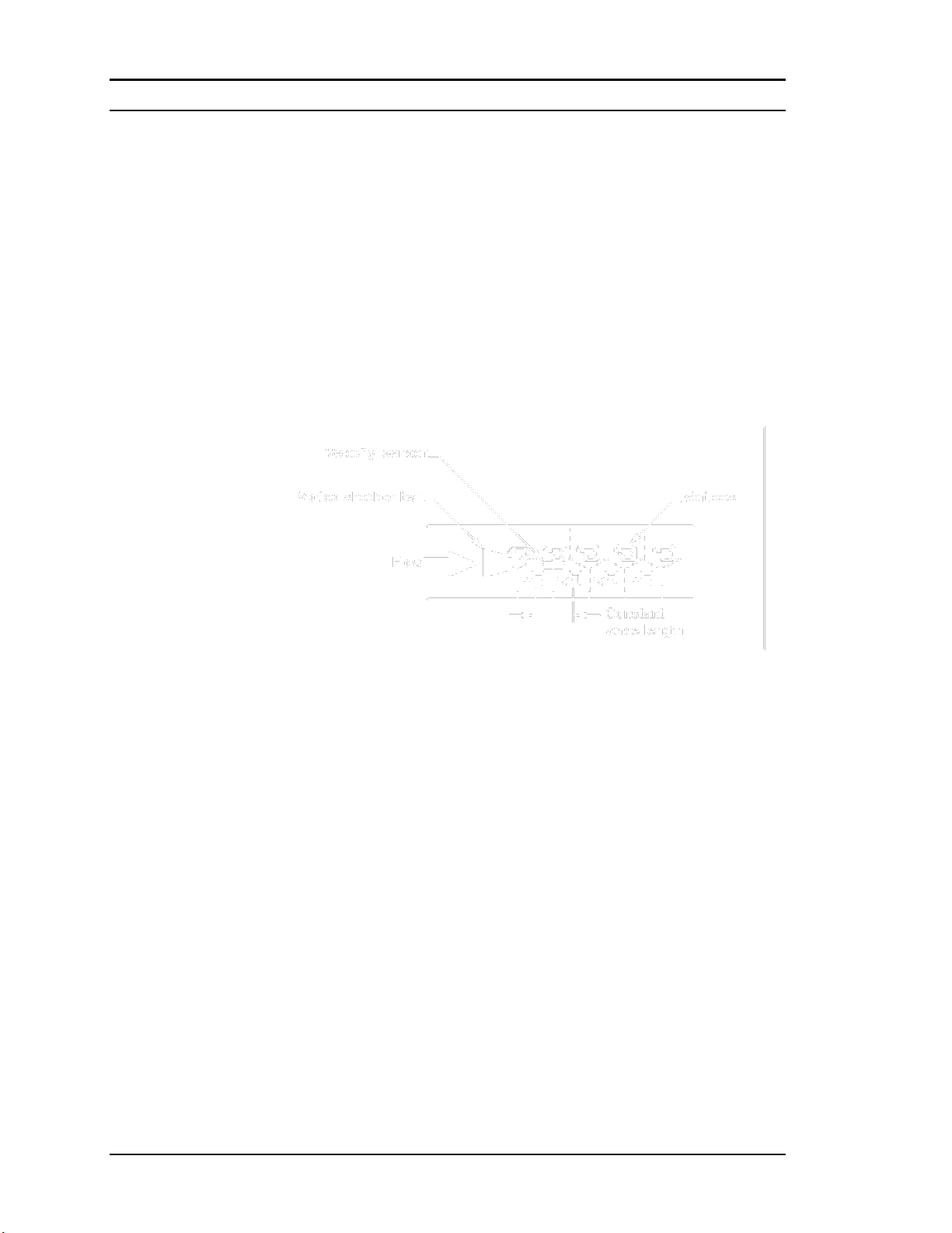
Vortex Shedding Frequency
Von Karman vortices form downstream of a shedder bar into two distinct
wakes. The vortices of one wake rotate clockwise while those of the other wake rotate counterclockwise. Vortices generate one at a time, alternating from the left side to the right side of the shedder bar. Vortices interact with their surrounding space by over-powering every other nearby
swirl on the verge of development. Close to the shedder bar, the distance
(or wave length) between vortices is always constant and measurable.
Therefore, the volume encompassed by each vortex remains constant, as
shown below. By sensing the number of vortices passing by the velocity
sensor, the InnovaMass flow meter computes the total fluid volume.
Figure 1-2. Measurement Principle of Vortex Flow Meters
Vortex Frequency Sensing
The velocity sensor incorporates a piezoelectric element that senses the
vortex frequency. This element detects the alternating lift forces produced by the Von Karman vortices flowing downstream of the vortex
shedder bar. The alternating electric charge generated by the piezoelectric element is processed by the transmitter’s electronic circuit to obtain
the vortex shedding frequency. The piezoelectric element is highly sensitive and operates over a wide range of flows, pressures and temperatures.
1-4 IM-240

Sierra 240/241 Series Instruction Manual Chapter 1 Introduction
Re =
V D
St =
f d
V
Gas
Liquid
Vmin
25
ft/s
1 ft/s
English (lb/ft3)
Vmax
300 ft/s
30 ft/s
Vmin
37
m/s
0.3 m/s
Metric (kg/m3)
Vmax
91 m/s
9.1 m/s
Flow Velocity Range
To ensure trouble-free operation, vortex flow meters must be correctly
sized so that the flow velocity range through the meter lies within the
measurable velocity range (with acceptable pressure drop) and the linear
range.
The measurable range is defined by the minimum and maximum velocity
using the following table.
The pressure drop for series 241 insertion meters is negligible. The pressure drop
for 240 Series in-line meters is defined as:
P = .00024 V
P = .000011 V
2
English units (P in psi, in lb/ft3, V in ft/sec)
2
Metric units (P in bar, in kg/m3, V in m/sec)
The linear range is defined by the Reynolds number. The Reynolds number is the
ratio of the inertial forces to the viscous forces in a flowing fluid and is defined
as:
Where
Re = Reynolds Number
= mass density of the fluid being measured
V = velocity of the fluid being measured
D = internal diameter of the flow channel
= viscosity of the fluid being measured
The Strouhal number is the other dimensionless number that quantifies the
vortex phenomenon. The Strouhal number is defined as:
Where
St = Strouhal Number
f = frequency of vortex shedding
d = shedder bar width
V = fluid velocity
IM-240 1-5

Chapter 1 Introduction Sierra 240/241 Series Instruction Manual
0.3
0.2
0.1
0.0
3 4
10
Linear range
Rey nolds Number, Re
Strouhal Number, St
10
5
10 10
8
10
6
10
7
5000
Corrected range
As shown in Figure 1-3, InnovaMass meters exhibit a constant Strouhal
number across a large range of Reynolds numbers, indicating a consistent linear output over a wide range of flows and fluid types. Below
this linear range, the intelligent electronics in InnovaMass automatically
corrects for the variation in the Strouhal number with the Reynolds number. The meter’s smart electronics corrects for this non-linearity via its
simultaneous measurements of the process fluid temperature and pressure. This data is then used to calculate the Reynolds number in real
time. InnovaMass meters automatically correct down to a Reynolds
number of 5,000.
Figure 1-3. Reynolds Number Range for the InnovaMass
Temperature Measurement
InnovaMass Flow Meters use a 1000 ohm platinum resistance temperature
detector (PRTD) to measure fluid temperature.
Pressure Measurement
InnovaMass Flow Meters incorporate a solid-state pressure transducer
isolated by a 316 stainless steel diaphragm. The transducer itself is micro-machined silicon, fabricated using integrated circuit processing technology. A nine-point pressure/temperature calibration is performed on
every sensor. Digital compensation allows these transducers to operate
within a 0.3% of full scale accuracy band within the entire ambient temperature range of -40°F to 140°F (-40 to 60°C). Thermal isolation of the
pressure transducer ensures the same accuracy across the allowable process fluid temperature range of -330°F to 750°F (-200 to 400°C).
1-6 IM-240

Sierra 240/241 Series Instruction Manual Chapter 1 Introduction
Flow Meter Configurations
InnovaMass Vortex Mass Flow Meters are available in two
model configurations:
240 Series in-line flow meter (replaces a section of the pipeline)
241 Series insertion flow meter (requires a “cold” tap or a “hot” tap
into an existing pipeline)
Both the in-line and insertion configurations are similar in that they both
use identical electronics and have similar sensor heads. Besides installation differences, the main difference between an in-line flow meter and
an insertion flow meter is their method of measurement.
For an in-line vortex flow meter, the shedder bar is located across the entire diameter of the flow body. Thus, the entire pipeline flow is included
in the vortex formation and measurement. The sensing head, which directly measures velocity, temperature and pressure is located just downstream of the shedder bar.
Insertion vortex flow meters have a shedder bar located across the diameter of a short tube. The velocity, temperature and pressure sensor are
located within this tube just downstream of a built-in shedder bar. This
entire assembly is called the insertion sensing head. It fits through any
entry port with a 1.875 inch minimum internal diameter.
The sensing head of an insertion vortex flow meter directly monitors the
velocity at a point in the cross-sectional area of a pipe, duct, or stack (referred to as “channels”). The velocity at a point in the pipe varies as a function of the Reynolds number. The insertion vortex flow meter computes the
Reynolds number and then computes the total flow rate in the channel. The
output signal of insertion meters is the total flow rate in the channel. The
accuracy of the total flow rate computation depends on adherence to the
piping installation requirements given in Chapter 2. If adherence to those
guidelines cannot be met, contact the factory for specific installation advice.
Multivariable Options
The 240 or 241 models are available with the following options:
V, volumetric flowmeter; VT, velocity and temperature sensors; VTP,
velocity, temperature, and pressure sensors; VT-EM energy output options; VTP-EM, energy options with pressure; VT-EP, external pressure
transmitter input.
IM-240 1-7

Chapter 1 Introduction Sierra 240/241 Series Instruction Manual
Line Size / Process Connections / Materials
The 240 In-line model is built for line sizes ½ through 4 inch wafer or ½
through 8 inch flanged design using ANSI 150, 300, 600, PN16, 40, or
64 class flanges.
The 241 Insertion model can be used in line sizes 2 inch and greater and
is built with a compression fitting or packing gland design using 2 inch
NPT, or 2 inch flanged connections (ANSI 150, 300, 600, PN16, 40, or
64 class flanges). The packing gland design can be ordered with a permanent or removable retractor.
The 240 In-line model can be built with A105 carbon steel, 316L stainless steel, or Hastelloy C-276. The 241 Insertion model can be built with
316L stainless steel or Hastelloy C-276.
Flow Meter Electronics
InnovaMass Flow Meter electronics are available mounted directly to the
flow body, or remotely mounted. The electronics housing may be used
indoors or outdoors, including wet environments. Available input power
options are: DC loop powered (2-wire), DC powered, or AC powered.
Three analog output signals are available for your choice of three of the
five process variables: mass flow rate, volumetric flow rate, temperature,
pressure or fluid density. A pulse output signal for remote totalization
and MODBUS or HART communications are also available.
InnovaMass Flow Meters include a local 2 x 16 character LCD display
housed within the enclosure. Local operation and reconfiguration is accomplished using six pushbuttons operated via finger touch. For hazardous locations, the six buttons can be operated with the electronics enclosure sealed using a hand-held magnet, thereby not compromising the integrity of the hazardous location certification.
The electronics include nonvolatile memory that stores all configuration
information. The nonvolatile memory allows the flow meter to function
immediately upon power up, or after an interruption in power. All
flowmeters are calibrated and configured for the customer’s flow
application.
1-8 IM-240

Sierra 240/241Series Instruction Manual Chapter 2 Installation
Warning!
Consult the flow meter nameplate for
specific flow meter approvals before any
hazardous location installation.
Chapter 2 Installation
Installation Overview
Sierra’s InnovaMass Vortex Flow Meter installations are simple and
straightforward. Both the 240 In-Line and 241 Insertion type flow meter
installations are covered in this chapter. After reviewing the installation
requirements given below, see page 2-3 for 240 installation instructions.
See page 2-6 for 241 installation instructions. Wiring instructions begin
on page 2-20.
Flow Meter Installation Requirements
Before installing the flow meter, verify the installation site allows for
these considerations:
1. Line pressure and temperature will not exceed the flow meter
rating.
2. The location meets the required minimum number of pipe di-
ameters upstream and downstream of the sensor head as illustrated in Figure 2-1.
3. Safe and convenient access with adequate overhead clear-
ance for maintenance purposes.
4. Verify that the cable entry into the instrument meets the
specific standard required for hazardous area installations.
The cable entry device shall be of a certified flameproof
type, suitable for the conditions of use and correctly installed. The degree of protection of at least IP66 to EN
60529 is only achieved if certified cable entries are used
that are suitable for the application and correctly installed.
Unused apertures shall be closed with suitable blanking elements.
5. For remote installations, verify the supplied cable length is
sufficient to connect the flow meter sensor to the remote
electronics.
Also, before installation check your flow system for anomalies such as:
• leaks
• valves or restrictions in the flow path that could create disturb-
ances in the flow profile that might cause unexpected flow rate indications
IM-240 2-1

Chapter 2 Installation Sierra 240/241Series Instruction Manual
Minimum Required
Upstream
Diameters
Minimum Required
Downstream Diameters
Example A B 1 10 D
5 D 2 15 D
5 D 3 25 D
10 D
4
10 D
5 D
5
20 D
5 D
6
25 D
10 D
D=Internal diameter of channel. N/A=Not applicable
Unobstructed Flow Requirements
Select an installation site that will minimize possible distortion in the flow
profile. Valves, elbows, control valves and other piping components may
cause flow disturbances. Check your specific piping condition against the
examples shown below. In order to achieve accurate and repeatable performance install the flow meter using the recommended number of
straight run pipe diameters upstream and downstream of the sensor.
Note: For liquid applications in vertical pipes, avoid installing with flow
in the downward direction because the pipe may not be full at all points.
Choose to install the meter with flow in the upward direction if possible.
2-2 IM-240
Figure 2-1. Recommended Pipe Length Requirements for Installation, 240/241 Series

Sierra 240/241Series Instruction Manual Chapter 2 Installation
Stud Bolt Lengths for Each Flange Rating (inches)
Line Size
Class 150
and PN16
Class 300
and PN40
Class 600
and PN64
1 inch
6.00
7.00
7.50
1.5 inch
6.25
8.50
9.00
2 inch
8.50
8.75
9.50
3 inch
9.00
10.00
10.50
4 inch
9.50
10.75
12.25
240 In-Line Flow Meter Installation
Install the 240 In-Line Flow Meter between two conventional pipe flanges
as shown in Figures 2-3 and 2-4. Table 2-1 provides the recommended
minimum stud bolt lengths for wafer-style meter body size and different
flange ratings.
The meter inside diameter is equal to the same size nominal pipe ID in
schedule 80. For example, a 2” meter has an ID of 1.939” (2” schedule
80). Do not install the meter in a pipe with an inside diameter smaller
than the inside diameter of the meter. For schedule 160 and higher
pipe, a special meter is required. Consult the factory before purchasing
the meter.
The InnovaMass 240 meters require customer-supplied gaskets. When selecting gasket material make sure that it is compatible with the process
fluid and pressure ratings of the specific installation. Verify that the inside
diameter of the gasket is larger than the inside diameter of the flow meter
and adjacent piping. If the gasket material extends into the flow stream, it
will disturb the flow and cause inaccurate measurements.
Flange Bolt Specifications
Table 2-1. Minimum Recommended Stud Bolt Lengths for Wafer Meters
The required bolt load for sealing the gasket joint is affected by several
application-dependent factors, therefore the required torque for each application may be different. Refer to the ASME Pressure Vessel Code
guidelines for bolt tightening standards.
1
34
2
1
8
6
5
34
7
2
4
10
1
12
8
6
5
9
3
7
11
2
4-bolt 8-bolt 12-bolt
Figure 2-2. Flange Bolt Torquing Sequence
IM-240 2-3
Chapter 2 Installation Sierra 240/241Series Instruction Manual
Caution!
When using toxic or corrosive
gases, purge the line with inert
gas for a minimum of four hours
at full gas flow before installing
the flow meter.
Wafer-Style Flow Meter Installation
Install the wafer-style meter between two conventional pipe flanges of the
same nominal size as the flow meter. If the process fluid is a liquid, make
sure the meter is located where the pipe is always full. This may require
locating the meter at a low point in the piping system. Note: Vortex flow
meters are not suitable for two-phase flows (i.e., liquid and gas mixtures).
For horizontal pipelines having a process temperature above 300° F,
mount the meter at a 45 or 90-degree angle to avoid overheating the electronics enclosure. To adjust the viewing angle of the enclosure or display/keypad, see page 2-18 and 2-19.
2-4 IM-240
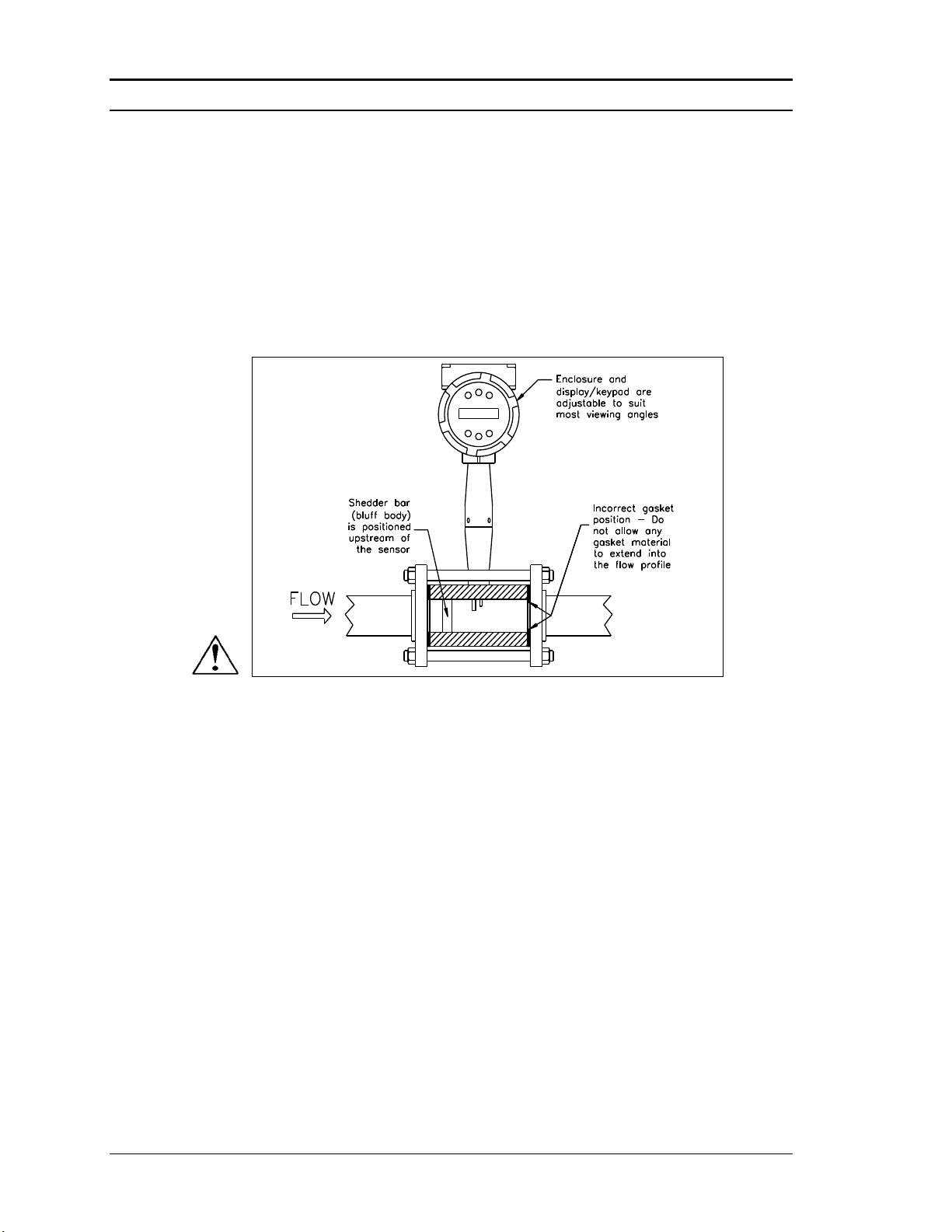
Figure 2-3. Wafer-Style Flow Meter Installation
When installing the meter make sure the section marked with a flow arrow is positioned upstream of the outlet, with the arrow head pointing in the direction of
flow. (The mark is on the wafer adjacent to the enclosure mounting neck.) This
ensures that the sensor head is positioned downstream of the vortex shedder bar
and is correctly aligned to the flow. Installing the meter opposite this direction
will result in completely inaccurate flow measurement. To install the meter:
1. Turn off the flow of process gas, liquid or steam. Verify that the line
is not pressurized. Confirm that the installation site meets the required
minimum upstream and downstream pipe diameters.
2. Insert the studs for the bottom side of the meter body between the pipe
flanges. Place the wafer-style meter body between the flanges with the
end stamped with a flow arrow on the upstream side, with the arrow
head pointing in the direction of flow. Center the meter body inside the
diameter with respect to the inside diameter of the adjoining piping.
3. Position the gasket material between the mating surfaces. Make sure
both gaskets are smooth and even with no gasket material extending into the flow profile. Obstructions in the pipeline will disturb the flow and
cause inaccurate measurements.

Sierra 240/241Series Instruction Manual Chapter 2 Installation
Caution!
When using toxic or corrosive
gases, purge the line with inert
gas for a minimum of four hours
at full gas flow before installing
the flow meter.
4. Place the remaining studs between the pipe flanges. Tighten the nuts in
the sequence shown in Figure 2-2. Check for leaks after tightening the
flange bolts
Flange-Style Flow Meter Installation
Install the flange-style meter between two conventional pipe flanges of
the same nominal size as the flow meter. If the process fluid is a liquid,
make sure the meter is located where the pipe is always full. This may require locating the meter at a low point in the piping system. Note: Vortex
flow meters are not suitable for two-phase flows (i.e., liquid and gas mixtures). For horizontal pipelines having a process temperature above 300°
F, mount the meter at a 45 or 90-degree angle to avoid overheating the
electronics enclosure. To adjust the viewing angle of the enclosure or display/keypad, see page 2-18 and 2-19.
IM-240 2-5
Figure 2-4. Flange-Style Flow Meter Installation
When installing the meter make sure the flange marked with a flow arrow is positioned upstream of the outlet flange, with the arrow head pointing in the direction of
flow. (The mark is on the flange adjacent to the enclosure mounting neck.) This ensures that the sensor head is positioned downstream of the vortex shedder bar and is
correctly aligned to the flow. Installing the meter opposite this direction will result in
completely inaccurate flow measurement. To install the meter:
1. Turn off the flow of process gas, liquid or steam. Verify that the line
is not pressurized. Confirm that the installation site meets the required
minimum upstream and downstream pipe diameters.

Chapter 2 Installation Sierra 240/241Series Instruction Manual
1.875-i nch mi n.
valve bo re
2-inch mi n.
2-inch
valve size
Isolation Valve Requirements
2. Seat the meter level and square on the mating connections with the flange
stamped with a flow arrow on the upstream side, with the arrow head
pointing in the direction of flow. Position a gasket in place for each side.
Make sure both gaskets are smooth and even with no gasket material extending into the flow profile. Obstructions in the pipeline will disturb the
flow and cause inaccurate measurements.
3. Install bolts in both process connections. Tighten the nuts in the se-
quence shown in Figure 2-2. Check for leaks after tightening the flange
bolts.
241 Insertion Flow Meter Installation
Prepare the pipeline for installation using either a cold tap or hot tap
method described on the following pages. Refer to a standard code for all
pipe tapping operations. The following tapping instructions are general in
nature and intended for guideline purposes only. Before installing the meter, review the mounting position and isolation value requirements given
below.
Mounting Position
Allow clearance between the electronics enclosure top and any other obstruction when the meter is fully retracted.
Isolation Valve Selection
An isolation valve is available as an option with 241 meters. If you supply
the isolation valve, it must meet the following requirements:
1. A minimum valve bore di-
ameter of 1.875 inches is re-
quired, and the valve’s body
size should be two inches.
Normally, gate valves are
used.
2. Verify that the valve’s body
and flange rating are within
the flow meter’s maximum
operating pressure and temperature.
3. Choose an isolation valve with at least two inches existing between
the flange face and the gate portion of the valve. This ensures that the
flow meter’s sensor head will not interfere with the operation of the
isolation valve.
2-6 IM-240

Sierra 240/241Series Instruction Manual Chapter 2 Installation
Caution!
When using toxic or
corrosive gases, purge
the line with inert gas
for a minimum of four
hours at full gas flow
before installing the
flow meter.
Warning!
All flow meter connec-
tions, isolation valves
and fittings for cold tap-
ping must have the same
or higher pressure rating
as the main pipeline.
Cold Tap Guidelines
Refer to a standard code for all pipe tapping operations. The following
tapping instructions are general in nature and intended for guideline purposes only.
1. Turn off the flow of process gas, liquid or steam. Verify that the line
is not pressurized.
2. Confirm that the installation site meets the minimum upstream and
downstream pipe diameter requirements. See Figure 2-1.
3. Use a cutting torch or sharp cutting tool to tap into the pipe. The pipe
opening must be at least 1.875 inches in diameter. (Do not attempt to
insert the sensor probe through a smaller hole.)
4. Remove all burrs from the tap. Rough edges may cause flow profile
distortions that could affect flow meter accuracy. Also, obstructions
could damage the sensor assembly when inserting into the pipe.
5. After cutting, measure the thickness of the cut-out and record this
number for calculating the insertion depth.
6. Weld the flow meter pipe con-
nection on the pipe. Make sure
this connection is within ± 5°
perpendicular to the pipe centerline.
7. Install the isolation valve (if
used).
8. When welding is complete and all fittings are installed, close the
isolation valve or cap the line. Run a static pressure check on the
welds. If pressure loss or leaks are detected, repair the joint and retest.
9. Connect the meter to the pipe process connection.
10. Calculate the sensor probe insertion depth and insert the sensor probe
into the pipe as described on the following pages.
IM-240 2-7

Chapter 2 Installation Sierra 240/241Series Instruction Manual
Warning!
Hot tapping must be
performed by a trained
professional. US. regulations
often require a hot tap permit.
The manufacturer of the hot
tap equipment and/or the
contractor performing the hot
tap is responsible for provid-
ing proof of such a permit.
Warning!
All flow meter connections,
isolation valves, and fittings
for hot tapping must have the
same or higher pressure
rating as the main pipeline.
Hot Tap Guidelines
Refer to a standard code for all pipe tapping operations. The following
tapping instructions are general in nature and intended for guideline purposes only.
1. Confirm that the installation site meets the minimum upstream and
downstream pipe diameter requirements.
2. Weld a two inch mounting adapter on the pipe. Make sure the mount-
ing adapter is within ± 5° perpendicular to the pipe centerline (see
previous page). The pipe opening must be at least 1.875 inches in diameter.
3. Connect a two inch process connection on the mounting adapter.
4. Connect an isolation valve on the process connection. The valve’s full
open bore must be at least 1.875 inches in diameter.
5. Run a static pressure check on the welds. If pressure loss or leaks are
detected, repair the joint and re-test.
6. Connect the hot tapping equipment to the isolation valve, open the
isolation valve and drill at least a 1.875 inch diameter hole.
7. Retract the drill, close the isolation valve, and remove the hot tapping
equipment.
8. Connect the flow meter to the isolation valve and open the isolation
valve.
9. Calculate the sensor probe insertion depth and insert the sensor probe
into the pipe as described on the following pages.
2-8 IM-240

Sierra 240/241Series Instruction Manual Chapter 2 Installation
Connect isolation
valve and test for
leaks
xxxxxxxxxxxxxxxxxxxx
xxxxxxxxxxxxxxxxxxxx
xxxxxxxxxxxxxxxxxxxx
xxxxxxxxxxxxxxxxxxxx
Purge pipe
Figure 2-5. Hot Tap Sequence
IM-240 2-9

Chapter 2 Installation Sierra 240/241Series Instruction Manual
Warning!
An insertion tool must be
used for any installation
where a flow meter is
inserted under pressure
greater than 50 psig.
Flow Meter Insertion
The sensor head must be properly positioned in the pipe. For this reason,
it is important that insertion length calculations are carefully followed. A
sensor probe inserted at the wrong depth in the pipe will result in inaccurate readings.
Insertion flow meters are applicable to pipes 2 inch and larger. For pipe
sizes ten inches and smaller, the centerline of the meter’s sensing head is
located at the pipe’s centerline. For pipe sizes larger than ten inches, the
centerline of the sensing head is located in the pipe’s cross section five
inches from the inner wall of the pipe; i.e., its “wetted” depth from the
wall to the centerline of the sensing head is five inches.
Insertion flow meters are available in three probe lengths:
Standard Probe configuration is used with most flow meter process
connections. The length, S, of the stem is 29.47 inches.
Compact Probe configuration is used with compression fitting process
connections. The length, S, of the stem is 13.1 inches.
12-Inch Extended Probe configuration is used with exceptionally lengthy
flow meter process connections. The length, S, of the stem is 41.47 inches.
2-10 IM-240
Use the Correct Insertion Formula
Depending on your flow meter’s process connection, use the applicable
insertion length formula and installation procedure as follows:
• Flow meters with a compression type connection (NPT or flanged)
follow the instructions beginning on page 2-11.
• Flow meters with a packing gland type connection (NPT or flanged)
configured with an insertion tool, follow the instructions beginning on
page 2-13.
• Flow meters with a packing gland type connection (NPT or flanged)
without an insertion tool, follow the instructions beginning on page
2-16.
Sierra 240/241Series Instruction Manual Chapter 2 Installation
Installing Flow Meters with a Compression Connection*
Use the following formula to determine insertion length for flow meters
(NPT and flanged) with a compression process connection. The installation procedure is given on the next page.
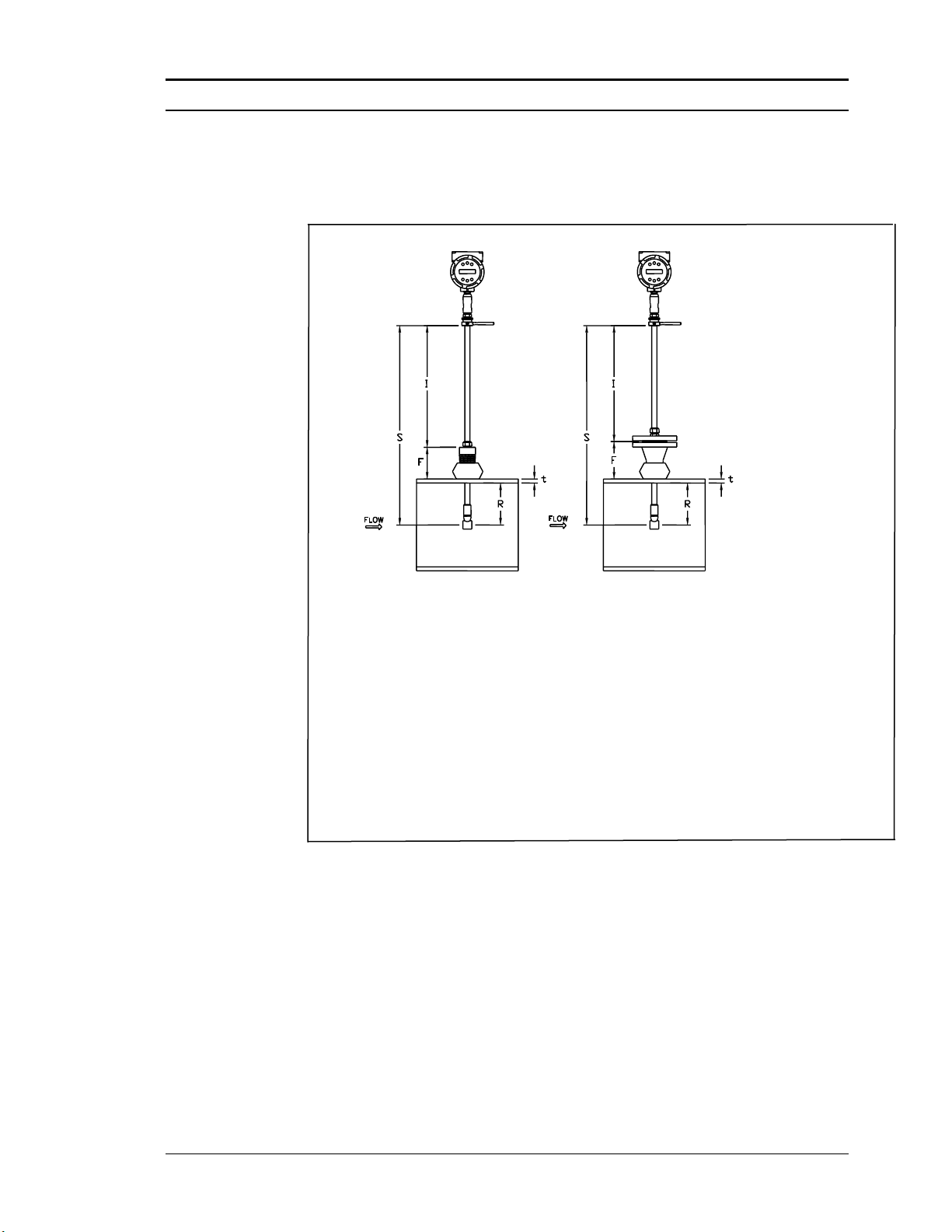
Insertion Length Formula
I = S – F – R – t
Where:
I = Insertion length.
S = Stem length – the distance from the center of the sensor head to the base
of the enclosure adapter (S = 29.47 inches for standard probes; S = 13.1
inches for compact; S = 41.47 inches for 12-inch extended).
F = Distance from the raised face of the flange or top of NPT stem housing to
the outside of the pipe wall.
R = Pipe inside diameter 2 for pipes ten inches and smaller.
R = Five inches for pipe diameters larger than ten inches.
t = Thickness of the pipe wall. (Measure the disk cut-out from the tapping
procedure or check a piping handbook for thickness.)
Figure 2-6. Insertion Calculation (Compression Type)
Example:
To install a 241 meter with a standard probe (S = 29.47 inches) into a 14 inch
schedule 40 pipe, the following measurements are taken:
F=3 inches
R=5 inches
t=0.438 inches
The insertion length for this example is 21.03 inches. Insert the stem through
the fitting until an insertion length of 21.03 inches is measured with a ruler.
*All dimensions are in inches
IM-240 2-11

Chapter 2 Installation Sierra 240/241Series Instruction Manual
Caution!
The sensor alignment
pointer must point
downstream, in the
direction of flow.
Warning!
To avoid serious injury,
DO NOT loosen the
compression fitting
under pressure.
Insertion Procedure for Meters with a Compression Connection
2-12 IM-240
Figure 2-7. Flow Meter with Compression Type Fitting
1. Calculate the required sensor probe insertion length.
2. Fully retract the stem until the sensor head is touching the bottom of
the stem housing. Slightly tighten the compression nut to prevent
slippage.
3. Bolt or screw the flow meter assembly into the process connection.
Use Teflon tape or pipe sealant to improve the seal and prevent seizing on NPT styles.
4. Hold the meter securely while loosening the compression fitting. In-
sert the sensor into the pipe until the calculated insertion length, I, is
measured between the base of the enclosure adapter and the top of
the stem housing, or to the raised face of the flanged version. Do
not force the stem into the pipe.
5. Align the sensor head using the sensor alignment pointer. Adjust the
alignment pointer parallel to the pipe and pointing downstream.
6. Tighten the compression fitting to lock the stem in position. When
the compression fitting is tightened, the position is permanent.

Sierra 240/241Series Instruction Manual Chapter 2 Installation
Installing Flow Meters with a Packing Gland Connection*
Use the formula below to determine the insertion depth for flow meters
(NPT and flanged) equipped with an insertion tool. To install, see the next
page for instructions for meters with a permanent insertion tool. For meters with a removable insertion tool, see page 2-15.
Insertion Length Formula
I = F + R + t – 1.35
Where:
I = Insertion length.
F = Distance from the raised face of the flange or top of
the process connection for NPT style meters to the top
outside of the process pipe.
R = Pipe inside diameter 2 for pipes ten inches & smaller.
R = Five inches for pipe diameters larger than ten inches.
t = Thickness of the pipe wall. (Measure the disk cutout from the tapping procedure or check a piping handbook for thickness.)
Figure 2-8. Insertion Calculation (Meters with Insertion Tool)
Example 1: Flange Style Meters:
To install a 241 Flow Meter into a 14 inch schedule 40 pipe, the following
measurements are taken:
F = 12 inches
R = 5 inches
t = 0.438 inches
The example insertion length is 16.09 inches.
Example 2: NPT Style Meters:
The length of thread engagement on the NPT style meters is also subtracted in
the equation. The length of the threaded portion of the NPT meter is 1.18
inches. Measure the thread portion still showing after the installation and subtract that amount from 1.18 inches. This gives you the thread engagement
length. If this cannot be measured use .55 inch for this amount.
F = 12 inches
R = 5 inches
The example insertion length is 15.54 inches.
*All dimensions are in inches.
t = 0.438 inches
IM-240 2-13

Chapter 2 Installation Sierra 240/241Series Instruction Manual
Caution!
The sensor alignment
pointer must point
downstream, in the
direction of flow.
Note
If line pressure is above
500 psig, it could require
up to 25 ft lb of torque to
insert the flow meter.
Do not confuse this with
possible interference
in the pipe.
Insertion Procedure for Flow Meters with Permanent Insertion Tool
2-14 IM-240
Figure 2-9. Flow Meter with Permanent Insertion Tool
1. Calculate the required sensor probe insertion length (see previous
page). Measure from the depth marker arrow down the stanchion and
scribe a mark at the calculated insertion depth.
2. Fully retract the flow meter until the sensor head is touching the bot-
tom of the stem housing. Attach the meter assembly to the two inch
full-port isolation valve, if used. Use Teflon tape or pipe sealant to
improve seal and prevent seizing on NPT style.
3. Loosen the two packing gland nuts on the stem housing of the meter.
Loosen the stem lock bolt adjacent to the sensor alignment pointer.
Align the sensor head using the sensor alignment pointer. Adjust the
alignment pointer parallel to the pipe and pointing downstream. Tighten
the stem lock bolt to secure the sensor position.
4. Slowly open the isolation valve to the full open position. If necessary,
slightly tighten the two packing gland nuts to reduce the leakage
around the stem.
5. Turn the insertion tool handle clockwise to insert the sensor head into
the pipe. Continue until the top of the upper retractor bracket aligns
with the insertion length position scribed on the stanchion. Do not
force the stem into the pipe.
6. Tighten the packing gland nuts to stop leakage around the stem. Do
not torque over 20 ft-lb.

Caution!
The sensor alignment
pointer must point
downstream, in the
direction of flow.
Note
If line pressure is above
500 psig, it could require
up to 25 ft lb of torque to
insert the flow meter.
Do not confuse this with
possible interference
in the pipe.
Sierra 240/241Series Instruction Manual Chapter 2 Installation
Insertion Procedure for Flow Meters with Removable Insertion Tool
Figure 2-10. Flow Meter with Removable Insertion Tool
1. Calculate the required sensor probe insertion length. Measure from
the depth marker arrow down the stanchion and scribe a mark at the
calculated insertion depth.
2. Fully retract the flow meter until the sensor head is touching the bot-
tom of the stem housing. Attach the meter assembly to the two inch
full-port isolation valve, if used. Use Teflon tape or pipe sealant to
improve seal and prevent seizing on NPT style.
3. Remove the two top stem clamp nuts and loosen two stem clamp
bolts. Slide the stem clamp away to expose the packing gland nuts.
4. Loosen the two packing gland nuts. Loosen the stem lock bolt adja-
cent to the sensor alignment pointer. Align the sensor head using the
sensor alignment pointer. Adjust the alignment pointer parallel to the
pipe and pointing downstream. Tighten the stem lock bolt to secure
the sensor position.
5. Slowly open the isolation valve to the full open position. If necessary,
slightly tighten the two packing gland nuts to reduce the leakage
around the stem.
6. Turn the insertion tool handle clockwise to insert the stem into the
pipe. Continue until the top of the upper retractor bracket lines up
with the insertion length mark scribed on the stanchion. Do not force
the stem into the pipe.
IM-240 2-15
 Loading...