

Page 1
Equipment for Machine Tools
WS 720 A
Single axis controller
User’s Guide Edition 10.93
COM 720 description
Siemens Automation Parts
Page 2
WS 720 A
Single axis controller
Catalogue Index of Manuals
Product brief
Description
SIEMENS
WS 720 A
SIEMENS
WS 720 A
SIEMENS
Index of Manuals
SIEMENS
General Documentation
Planning Manual Hardware
User and Service-Documentation (for details see inside back cover)
Description
PG-Manual
SIEMENS
Additional Documentation
Application Manual
User´s Guide for
OP 720
COM 720
SIEMENS
SIMATIC S5
Single Axis Controller
SIEMENS
WS 720 A
SIEMENS
WS 720 A
SIEMENS
Ausrüstungen für Bearbeitungsmaschinen
WS 720
Einachssteuerung
SIEMENS
WS 720 A
SIEMENS
WS 720 A
Reference Book, Lists
SIEMENS
Electro-Magnetic Guidelines
for WF/WS-Technology
Electro-Magnetic Guidelines
Equipment for Special Machines
Glossary of terms
(available only in German)
(available only in German)
Equipment for Special Machines
Equipment for Special Machines
Equipment for Special Machines
Equipment for Special Machines
Equipment for Special Machines
Equipment for Special Machines
Equipment for Special Machines
Equipment for Special Machines
Equipment for Special Machines
Single Axis Controller
Single Axis Controller
Single Axis Controller
Single Axis Controller
Single Axis Controller
Page 3
Edition October 1993
Equipment for
Machine Tools
WS 720 A
Single axis controller
User’s Guide
for COM 720
Forward
1
Function overview
2
Layout and Installation
3
Working with the software
4
Menu functions
5
Hints when using Windows
6
Appendix
7
Siemens Automation Parts
Page 4

Note
For the sake of clarity this document does not go into all possible situations which may
arise with this product. The document cannot deal with every situation which may arise
during commissioning, operation and maintenance.
If you need special information or have special questions, you should contact your
Siemens representative.
This document is not part of an earlier or existing agreement, promise or right. All
obligations of Siemens are limited to those in the sale contract, which also contains all the
details of the guarantee. The guarantee in the sale contract is not affected by anything in
this document.
BERO, SIMATIC, S I MODRIVE, SINEC, SINUMERIK, STEP are all regi s tered trademarks of Siemens
Aktiengesellschaf t.
The other terms used in this m anual m ay also be trademarks, whose use by third parties may infringe upon t he
rights of the owners of thos e t radem arks
This publication was produced with Microsoft Word 2.0b
Subject to technical changes.
The reproduction, transmission or use of this document or of its
contents is not permitted without express written authority.
Offenders will be liable for damages. All rights, including rights
supplied by patent grant or registration of a utility model or
design, are reserved.
Siemens AG 1993 All Rights Reserved
Page 5

10.99 Appendix
Contents
Page
1 Forward..................................................................................1-1
2 Function overview.................................................................2-1
3 Layout and Installation.........................................................3-1
3.1 Hardware and software overview.............................................................3-1
3.2 Hardware- and Software configuration....................................................3-2
3.3 Installing the COM 720 software.............................................................. 3-2
3.4 Installation of SYSDOK 720..................................................................... 3-2
4 Working with the software....................................................4-1
4.1 Starting display........................................................................................ 4-1
4.2 The machine file ...................................................................................... 4-2
4.3 Selection of data type.............................................................................. 4-3
4.4 Machine data........................................................................................... 4-4
4.5 Part Programs..........................................................................................4-5
4.6 Commissioning display............................................................................4-6
4.7 Transfer ................................................................................................... 4-7
4.8 Technical documentation (SYSDOK 720)................................................4-8
5 Menu functions......................................................................5-1
6 Hints when using Windows..................................................6-1
7 Appendix................................................................................7-1
7.1 Abbreviations...........................................................................................7-1
7.2 Index........................................................................................................ 7-3
Siemens Automation Parts
Page 6

10.99 Forward
Siemens AG 1993 All Rights Reserved 6ZB5 440-0RV02
1 - 1
WS 720 A (BN - COM 720 description)
1 Forward
What information is to be
found in this manual?
This pocket guide describes the installation and use of the COM
720 software. The hardware and software requirements are
specified. Some masks are explained with examples.
For whom is this manual
intended?
The guide is intended for machine design engineers and for
service specialists.
Each group, engineers and specialists must be qualified as
outlined on page 1-2.
What prior knowledge is
needed?
It is assumed that the user of this guide is familiar with general
machine safety guidelines and particular safety requirements of
the country where the machine is to be used.
Familiarity with Windows and with the modules WS721/WS720
are needed to be able to use the COM 720 software.
Finding your way about the
manual?
The manual is divided up into the sections:
ã
Overview
ã
Installation
ã
Operation
The guide is complemented by a function overview, hints to
using Windows, and lists of the functions in the menus and of
the pushbuttons.
Page 7
Forward 10.99
1 - 2 Siemens AG 1993 All Rights Reserved 6ZB5 440-0RV02
WS 720 A (BN - COM 720description)
Definitions and terminology
Qualified personnel
People who are experienced in setting up, optimising and
operating machines and whose qualifications are
commensurate with the an activity, for example:
ã
Training and authorisation to switch power to electrical
circuits and equipment according to the recognised
standards, to earth such equipment and the mark up the
cables on such equipment
ã
Training in the maintenance of safety devices according to
the recognised standards.
ã
First aid training.
Danger
Loss of life, severe personal injurity or substantial damage to
property will result if proper precautions are not taken.
Warning
Loss of life, severe personal injurity or substantial damage to
property can result if proper precautions are not taken.
Caution
Minor personal injurity or property damage can result if proper
precautions are not taken.
☞
This symbol draws attention to important information about the
product or a particular part of the operating instructions.
&
This type of frame contains a reference to another manual.
Siemens Automation Parts
Page 8

10.99 Function overview
Siemens AG 1993 All Rights Reserved 6ZB5 440-0RV02
2 - 1
WS 720 A (BN - COM 720 description)
2 Function overview
Area of application
Ease of programmimg is very important with today’s machines
and COM 720 provides you with an NC editor. Sets of data can
be conveneintly generated, duplicated and modified.
The COM 720 software offers:
−
menu driven Windows operation
−
ability to add comments to programs,
−
Help screen in case of operator errors,
−
info system to offer concise programming tips,
−
print out facility for the WS data,
−
comments window,
−
central data storage,
−
ON or OFF line operation,
−
SYSDOK 720 (WS720 documentation integrated into
software).
Structure
All the data of the WS cards used in a particular SIMATIC S5
system can be grouped together in a machine specific file with
the COM 720 software.
The data structure makes it possible to organise the machine
data, part programs and control configuration. The WS data for
the WS721/WS720 can be stored either on the hard disc of the
PG/PC or on floppy.
COM 720 is also very useful during commissioning, where it can
be used to view status of signals and axis positions.
With the COM 720 software it is possible to see which data files
are present.
Operation
The COM 720 software uses the window structure. The user is
guided by messages into the desired window.
Programming
An NC editor can be used to enter the part programs.
The editor is not only a means of entering the part programs, but
it also carries out a check to see that the entered values are
within tolerance.
Comments can also be inserted with the part program, as an aid
to understanding the program. Each program block can have a
comment line upto 65 characters in length.
Using COM 720 it is also possible to issue the data for MDI
mode. Teach-in is also possible with the COM 720.
Page 9

Function overview 10.99
2 - 2 Siemens AG 1993 All Rights Reserved 6ZB5 440-0RV02
WS 720 A (BN - COM 720 description)
Help system
The help system is based on the SYSDOK 720, which is an
integral part of the software. SYSDOK 720 is the Application
Manual of the WS720 not in a book form, but in the software. It
can be called up the screen just like the paper manual can be
opened up.
With few keystrokes you can obtain information relevant to a
given problem, which makes the software very attractive for
newcomers to the WS system. On the one hand there are the
familiar index and contents table of the paper documentation, on
the other there are the electronic search methods for cross
referencing related subjects and other explanations.
There is a key word index to help you in your search. When a
key word is selected, SYSDOK 720 brings up a list of all the
masks which deal with that subject. The selected mask can be
displayed. The work is further facilitated by means of the
electronic book mark and note pad.
SYSDOK 720 is also available as a separate product.
Siemens Automation Parts
Page 10
10.99 Layout and Installation
Siemens AG 1993 All Rights Reserved 6ZB5 440-0RV02
3 - 1
WS 720 A (BN - COM 720 description)
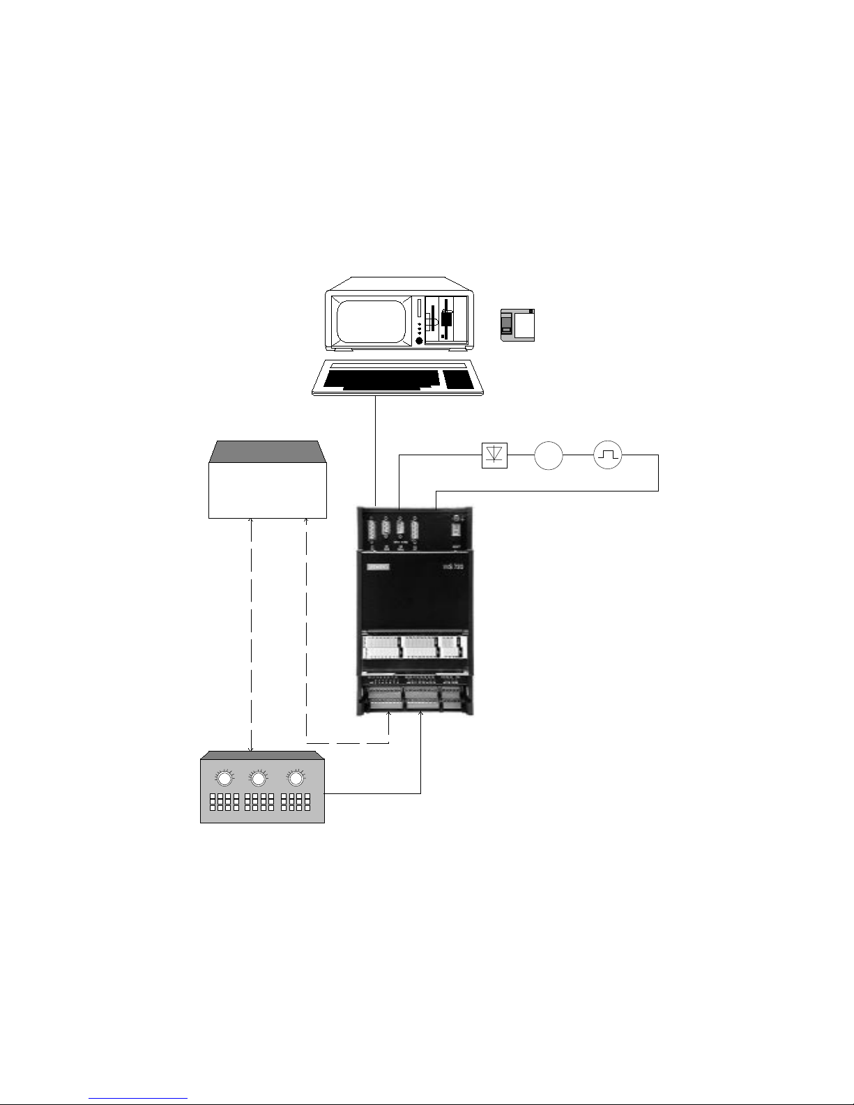
3 Layout and Installation
3.1 Hardware and software overview
M
PG 730/PG 750/PG 770/PC
COM 720
additional
possibility
digital
inputs/outputs
Relay
control
or
PLC
Page 11

Layout and Installation 10.99
3 - 2 Siemens AG 1993 All Rights Reserved 6ZB5 440-0RV02
WS 720 A (BN - COM 720 description)
3.2 Hardware- and Software configuration
• Hardware configuration
−
Programming units PG 730, PG 750, PG 770 or industrial standard PC with at least Intel
80386 or 80486 processor at least 4MB memory and a hard disc with at least a capacity
of 40MB
−
Appropriate cable from PG/PC to WS 720
−
Single axis controller WS720
−
Printer DR210, DR211, DR230, DR231
• Software configuration
−
MS-DOS 3.3 or higher
−
Microsoft Windows 3.1 or higher
3.3 Installing the COM 720 software
When all hardware and software requirements have been fulfilled, you can load the COM 720
software onto the hard disc of your PG or PC.
•
Find out in which path Windows is installed.
•
Insert the COM 720 disc into the drive and select this drive.
•
Start the installation program with the command INST720.
You will be guided through the installation. If you already have installed the COM 720 software
but wish to re-install, this is no problem. The old settings will be overwritten by the new.
3.4 Installation of SYSDOK 720
The help file
com720at.hlp
contains all the integrated documentation and is installed
automatically with the COM 720 software.
Siemens Automation Parts
Page 12

10.99 Working with the software
Siemens AG 1993 All Rights Reserved 6ZB5 440-0RV02
4 - 1
WS 720 A (BN - COM 720 description)
4 Working with the software
The idea behind the COM 720 software is to have an efficient tool with which to program the
WS720 single axis controller. The convenient operating system facilitates the manipulation of
machine data, part programs and control configurations.
The COM 720 software can be used either ON or OFF line
4.1 Starting display
This following display appears after the COM 720 software has been called up:
Fig. 4.1 Starting display
The field surrounding the is known as a "pushbutton". To proceed further with the
software, either click the "Continue" field with the mouse or press .
Page 13

Working with the software 10.99
4 - 2 Siemens AG 1993 All Rights Reserved 6ZB5 440-0RV02
WS 720 A (BN - COM 720 description)
4.2 The machine file
With the open machine file screen it is possible to either retrieve an existing file or open a new
file. The machine file groups all the WS720 specific data together.
Fig. 4.2 Open Machine file
Machine file name
The machine name can have upto 8 alphanumeric characters.
The extension "720" is added automatically.
Path
This displays the current path. The path
(drive):\com720\comanl
is set up automatically when the software is installed.
Already exist
Display (in alphabetical order) and selection of the currently
available machine files. Machine files which are already open
will be shown in square brackets in the in "Drive" box rather than
in the "Already exist" box.
Drive
Selection of the drive and path or of the machine files which are
already open.
Siemens Automation Parts
Page 14

10.99 Working with the software
Siemens AG 1993 All Rights Reserved 6ZB5 440-0RV02
4 - 3
WS 720 A (BN - COM 720 description)
4.3 Selection of data type
At this window the data type is selected, either machine data, part programs or control
configuration.
Fig. 4.3 Selection of dat a type
Title line
Display of the path and of the machine file name.
Data group name
Input field or display of the name of the selected data group. 10
alphanumeric characters are allowed. The list shows all the data
groups which contain the selected data type. "NONAME" will be
shown if no name has yet been issued.
Data branch or type
Selection of the data branch, whereby the possibilities are
machine data, part programs and OFFLINE control
configuration.
Page 15

Working with the software 10.99
4 - 4 Siemens AG 1993 All Rights Reserved 6ZB5 440-0RV02
WS 720 A (BN - COM 720 description)
4.4 Machine data
The machine data editor allows a "fill in the blanks" style of machine data determination. Machine
data which are related are grouped together in their own dialogs.
Fig. 4.4 Processing mac hine data
Title line
Display of machine file, data type and data group name.
MD No.
Selection of the machine datum to be processed.
Process
Call up the input dialog of the currently selected machine datum.
Machine data list
Individual machine data can be selected with the mouse or with
the cursor control. The input dialog for that machine datum can
be selected by pressing or with double click on the mouse.
The COM 720 help is called up by selecting the
in the machine data overview. The
SYSDOK 720 is called up by selecting the "Help" in the Input dialog
Siemens Automation Parts
Page 16

10.99 Working with the software
Siemens AG 1993 All Rights Reserved 6ZB5 440-0RV02
4 - 5
WS 720 A (BN - COM 720 description)
4.5 Part Programs
The part program editor allows a "fill in the blanks" approach to generating a part program. Each
entry is checked to see that it is within the appropriate limits. It is also possible to assign a text to
each program instruction.
Fig. 4.5 Editing part programs
Title line
Display of machine file, data type and data group name.
Editor line
The various data for each instruction can be inserted in the
editor line. The cursor can be moved with either or with the
mouse. The data are accepted into the program with or by
clicking
with the mouse.
Program list
Display of the program instructions (in ascending order). The
editor line is activated by pressing with the cursor on the
desired instruction or by giving the desired instruction a double
click with the mouse. Each field of the instruction is dealt with as
an input dialog in its own right, whereby the input possibilities
and the limits are also displayed.
Page 17

Working with the software 10.99
4 - 6 Siemens AG 1993 All Rights Reserved 6ZB5 440-0RV02
WS 720 A (BN - COM 720 description)
4.6 Commissioning display
The commissioning display offers welcome assistance during commissioning and trouble
shooting.The data in this display are continually updated.
Fig. 4.6 Commissioning dis pl ay
Firmware level
Display of the firmware level of the WS 720
Hardware level
Display of the hardware level of the WS 720
Operating mode
Display of the current operating mode
Selected program number
This field shows the nubmer of the current program when the
mode "Program number select" is active
SS
The current status of the control inputs
RS
The current status of the control outputs
WS status data
Display of the current control and program data, including such
data as following error, loop gain, current velocity, saved value
from block change on the fly, selected override
There are also soft keys for TEACH IN, MDI, velocity values in jog and to display motion fault
messages.
Siemens Automation Parts
Page 18

10.99 Working with the software
Siemens AG 1993 All Rights Reserved 6ZB5 440-0RV02
4 - 7
WS 720 A (BN - COM 720 description)
4.7 Transfer
The transfer dialog is the means whereby machine data and part programs can be moved
between WS and COM 720 software. The details for the source and destination are different
according to whether the dialog is called up from the editor or from the processing branch.
Fig. 4.7 Transfer
Title line
Display of the path and data group name
Direction
Transfer direction
Source/Destination
The source and destination fields are shown according to the
transfer direction
File
The file name for the source or destination
Editor
The editor for source or destination
Module
Which WS module is involved in the transfer
Data group name
Selection of the data to be transferred
Available
Display of the programs available in the WS 720 (only for
transfer of traversing programs)
Activate
The machine data are activated after the transfer from PG/PC
to WS
Command status
Status of the current command
Page 19

Working with the software 10.99
4 - 8 Siemens AG 1993 All Rights Reserved 6ZB5 440-0RV02
WS 720 A (BN - COM 720 description)
4.8 Technical documentation (SYSDOK 720)
The WS720 Application manual is integrated into the software.
SYSDOK 720 has its own order number (6ZB5 440-0TE02-2DA0). This version of
SYSDOK 720 corresponds to the 10.92 Version of the paper Application manual (order number
6ZB5 440-0RT02-0AA0).
Fig. 4.8 SYSDOK 720 example - looking at an error description
Overlays
Overlays are in green and underlined with a broken line. The
overlay will be shown when is pressed or with pressing the
left hand key on the mouse.
Jumps
Jumps are shown in green and underlined with a continuous
line.
&
The help system of Windows has been integrated into
SYSDOK 720. Please refer to your Windows manual for help
and information.
Siemens Automation Parts
Page 20

Menu functions 10.99
Siemens AG 1993 All Rights Reserved 6ZB5 440-0RV02
5 - 1
WS 720 A (BN - COM 720 description)
5 Menu functions
The functions in the menus can be called up from various screens. Each function has various
possibilities in the appropriate drop down menu. Any function which is grey is not available.
This chapter describes the functions currently available.
File Presets Diagnosis Info
Open
After selecting "Open" the dialog box will appear showing the
contents of the machine file
Store and continue
The current data group will be stored without leaving the editor.
Store and change
The current data group will be stored,the editor function is deselected and the system returns to the screen for selection of
"Processing branch".
Store and quit
he current data group will be stored,the editor function is deselected. Furthermore the machine file is closed and the screen
for "Open machine file" is selected.
Copy
−
Copy the selected machine file
−
Copy the selected data group from the current machine file to
another machine file
Delete
−
Delete the current machine file
−
Delete the current data group
Delete WS
−
Delete the part programs stored on the WS module
Transfer
Move the part programs or machine data between the COM 720
software and the WS module.
Activate hardcopy
With this function active, the current screen can be printed out
by pressing
.
Print
Print out of the machine file (in preparation).
Finish
Leaving the COM 720 software whereby all data will be stored
and the machine file will be closed.
Page 21

10.99 Menu functions
5 - 2 Siemens AG 1993 All Rights Reserved 6ZB5 440-0RV02
WS 720 A (BN - COM 720 description)
File Presets Diagnosis Info
Online/Offline With this selection it is possible to switch between online and
offline
EPROM Use this feature to store the data into EEPROM or to dowmload
from EEPROM to RAM.
File Presets Diagnosis Info
Commissioning display Use this feature to assist with commissioning or during fault
finding
File Presets Diagnosis Info
Windows Help Help information for Windows
Technical Help Call up for system integrated documentation SYSDOK 720
About COM 720 Information about the COM 720 software
Pushbuttons used
Quit the current menu and return to the previous level.
This is to call up the dialog.
Use this to view the motion fault messages
Use this display to view the velocity levels for jog mode
This pushbutton is used when processing machine data, to show
the limits of the relevant machine data.
Information about the current dialog
Siemens Automation Parts
Page 22

Menu functions 10.99
Siemens AG 1993 All Rights Reserved 6ZB5 440-0RV02
5 - 3
WS 720 A (BN - COM 720 description)
Confirm the question in the dialog box.
To enter a description for the data group.
Delete a movement block in the program list
Use this selection to call up MDI mode from the commissioning
display
Do not do the action described in the dialog box.
The selected machine file will be processed. The next selection
is made in the processing branch.
With "Online" the link is set up to the PLC and shut down again
with "Offline". On- or Off-line is displayed accordingly.
Accept the dialog
Close a machine file
Store the current file.
Use this selection to call up TEACH IN mode from the
commissioning display.
Accept the current data group.
Jump into the next processing level.
Page 23

Siemens Automation Parts
Page 24

10.99 Hints when using Windows
Siemens AG 1993 All Rights Reserved 6ZB5 440-0RV02
6 - 1
WS 720 A (BN - COM 720 description)
6 Hints when using Windows
You’ll need the following Windows commands to work with the COM 720 software:
Function
Tastaturfolge
Activate the menu bar
Confirm
Abort
Change between buttons and In/Output fields
Move within the current menu
;
Open system menu
"Hardcopy/hotkey"
Change the group window
ï
Activate hardcopy
h
To activate a function Press with the underlined letter.
Active functions These are highlighted in the preset colour in the menu.
Inactive functions These functions are in pale grey and cannot be selected.
Activate hardcopy Select in the data menu, an active function is indicated by a check mark.
An Enter always refers to the active window, the active window is highlighted with a differently
coloured frame. The Selection is made with the cursor keys and the Accept with the Enter key or
by positioning the mouse and double clicking the left mouse key.
The colours can be changed with Windows.
&
For further information on Windows, please see your "Windows" manual.
Page 25

Siemens Automation Parts
Page 26

10.99 Appendix
Siemens AG 1993 All Rights Reserved 6ZB5 440-0RV02
7 - 1
WS 720 A (BN - COM 720 description)
7 Appendix
7.1 Abbreviations
A-MF
Strobe signal for M functions
BE
Overtravel
BL
Program running
EFG
Read in enable
EZS
Single move
F
Fault bit
F
Feed rate
FUB
End of function bit
G1
G function in 1st group
G2
G function in 2nd group
M1
M function in 1st group
M2
M function in 2nd group
M3
M function in 3rd group
MD
Machine data
MDI
Manual Data Input
N
Block number
NC
Numerical control
NFB
Follow up mode
PBR
Program running backwards
PC
Personal computer
PEH
Position reached,axis stationary
PG
Programming unit
Q
Output
Q-MF
Acknowledge for M functions
Page 27

Appendix 10.99
7 - 2 Siemens AG 1993 All Rights Reserved 6ZB5 440-0RV02
WS 720 A (BN - COM 720 description)
RFG
Servo enable
RS
Output from WS
RST
Axis reset
RW
Axis moving backwards
RWL
Cancel remaining distance
SA
Block skip
SFG
Start enable
SS
WS inputs
SYN
Axis referenced
SYSDOK
System documentation integrated into software
T-L
Dwell time running
TIP+/-
positive/negative motion or positive/negative voltage output or positive/negative
rotation for rotary axis
VDE
German Electrical Assosiation
VW
Axis moving forwards
W1/W2
Velocity level 1 or 2 or Voltage level 1 or 2
WF
Machine tool module
WS
Machine tool control
X
Position /Dwell time
Siemens Automation Parts
Page 28

10.99 Appendix
Siemens AG 1993 All Rights Reserved 6ZB5 440-0RV02
7 - 3
WS 720 A (BN - COM 720 description)
7.2 Index
A
Abort .................................................. 5-2
Accept................................................ 5-3
Application manual............................. 4-8
Area of application............................. 2-1
C
Close.................................................. 5-3
Command status................................ 4-7
Comments.......................................... 5-3
Commissioning display...................... 4-6; 5-2
Continue............................................. 5-3
D
Data branch or type............................ 4-3
Data group name............................... 4-3; 4-7
Delete................................................. 5-3
Direction............................................. 4-7
E
Editor.................................................. 4-7
Editor line........................................... 4-5
EPROM.............................................. 5-2
F
Firmware level.................................... 4-6
Function overview.............................. 2-1
H
Hardware and software overview....... 3-1
Hardware level................................... 4-6
Hardware- and Software configuration 3-2
Help.................................................... 5-2
Help system ....................................... 2-2
Hints when using Windows................ 6-1
I
Installation of SYSDOK 720............... 3-2
Installing the COM 720 software........ 3-2
J
JOG.................................................... 4-6
Jumps................................................. 4-8
K
Kapitel................................................ 1-1
L
Layout and Installation....................... 3-1
Limits.................................................. 5-2
M
Machine data...................................... 4-4
Machine data list................................ 4-4
MD No................................................ 4-4
MDI..................................................... 4-6; 5-3
Menu functions................................... 5-1
Module............................................... 4-7
motion fault messages....................... 4-6
Move Faults........................................ 5-2
N
No ...................................................... 5-3
O
Offline................................................. 5-2
OK...................................................... 5-3
Online................................................. 5-2; 5-3
Open.................................................. 5-3
Operating mode ................................. 4-6
Operation........................................... 2-1
Overlays............................................. 4-8
P
part program editor............................. 4-5
Part Programs.................................... 4-5
Process.............................................. 5-2
Program list........................................ 4-5
Programming...................................... 2-1
Pushbuttons....................................... 5-2
Q
Qualified personnel............................ 1-2
R
RS...................................................... 4-6
S
Selected program number.................. 4-6
Selection of data type......................... 4-3
SS...................................................... 4-6
Starting display................................... 4-1
Store .................................................. 5-3
Structure............................................. 2-1
SYSDOK 720..................................... 4-8
Page 29

Appendix 10.99
7 - 4 Siemens AG 1993 All Rights Reserved 6ZB5 440-0RV01
WS 720 A (BN - Beschreibung COM 720)
T
TEACH IN .......................................... 4-6; 5-3
Technical documentation................... 4-8
Technical Help ................................... 5-2
The machine file................................. 4-2
Title line..............................................4-3; 4-4; 4-7
Transfer.............................................. 4-7
V
Velocity Levels................................... 5-2
W
Windows Help.................................... 5-2
Working with the software.................. 4-1
WS status data................................... 4-6
Y
Yes..................................................... 5-3
Siemens Automation Parts
Page 30

SIEMENS AG
Suggestions
Corrections
AUT V240
Postfach 4848
For Publication/Manual:
Equipment for Machine Tools
WS 720 A
Single Axis controller
Pocket Guide; COM 720 description
D-90327 Nürnberg
Fed. Rep. of Germany
Order No.: 6ZB5 440-0RV02-0AA1
Edition: October 1993
_
__
From:
Name:
Company/Dept:
Address:
Telephone:
If you find any printing errors when reading this
publication, please let us know, using this form. We also
welcome any suggestions to improve the manual.
Suggestions and/or corrections
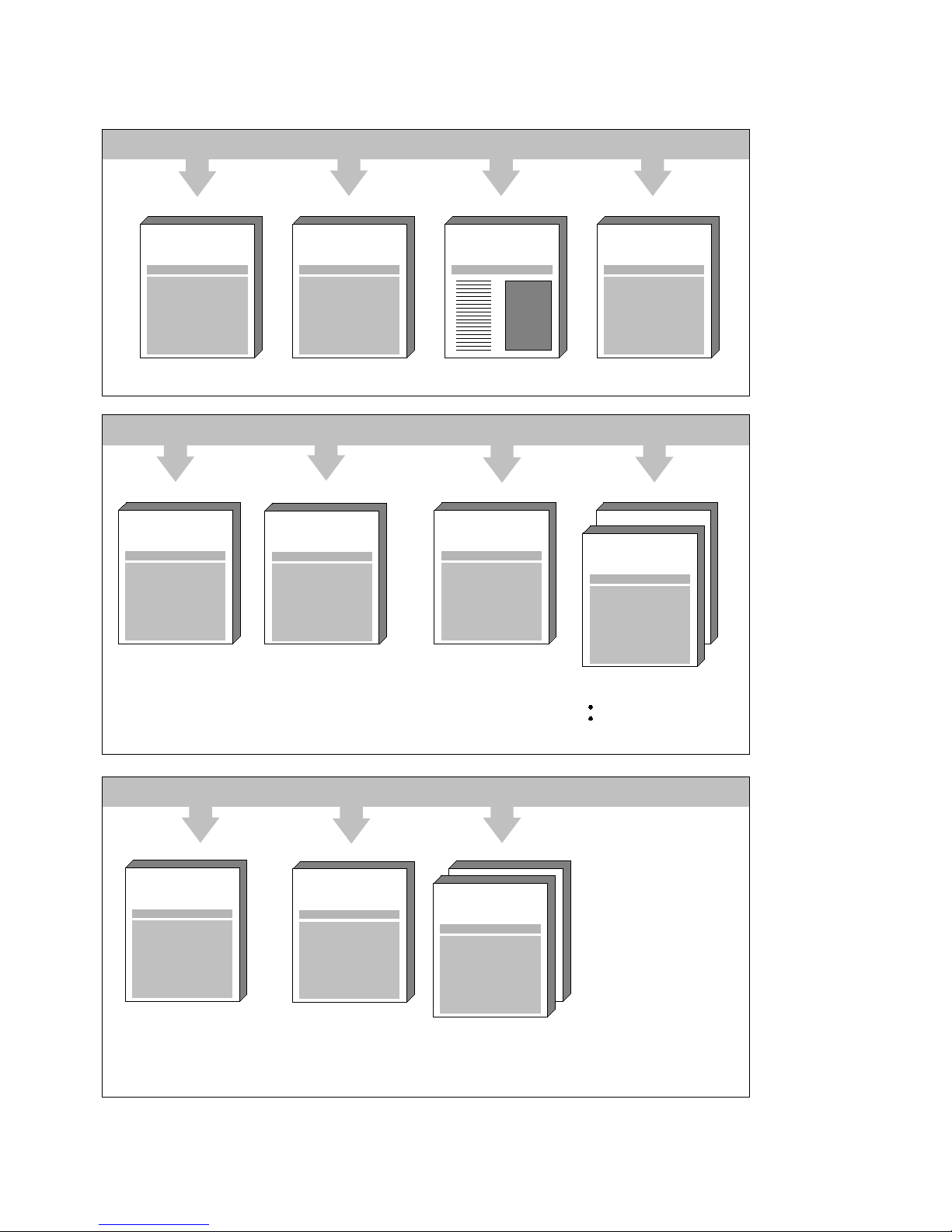
Page 31

Areas of Application
Further information about catalogues, manuals and training can be obtained from your local SIEMENS
office. This overview shows which documentation should be used for the various tasks:
Task
Documentation First contact Draft
Design and
Engineering
Installation and
Commissioning
Production
phase
Service
Product brief
Description
Catalogue
Application
Manual
Description of the
Hardware
Electro-Magnetic
Guidelines
Reference Book,
Lists
Description
COM 720
Description
OP 720
Glossary of terms
necessary useful
An overview over area of application and function of all WS/WF modules is given by the catalogue:
Equipment for Machine Tools
WS/WF-Technology • Systems and Components
Catalogue AR 10
This catalogue also contains the order numbers which are required for the planning.
The Trainings-Center offers courses in the positioning area which supply practical as well as theoretical
background. An overview of courses is given by the catalogue:
Information und Training
Courses for Automation Technology
Catalogue IT5
Siemens Automation Parts
Page 32

Types and Purposes of the WS 720 A-Documentation
Product brief
WS 720 A
Order no.: 6ZB5 440-0RL02-0BA0
Target group: Initial contact
(e.g. trade shows)
This colour brochure gives yor
information about:
• Layout
• Operating priciples
• Overall system
• COM 720
A list of the techni c al data of the
WS 720 rounds up the product brief
Description
WS 720 A
Order no.: 6ZB5 440-0RM02-0BA1
Target group: Purchasing,
designers at
machine builder,
plant engineering at
the end customer
This document gives detai l ed
information about:
• Area of application
• Layout
• Operating principles
• Operating
• Programming
• Technical data
• Order details
Description
Electro-magnetic Guidelines
Order no.: 6ZB5 440-0QX02-0BA1
Target group: Machine designers
commissioning and
service people
This document goes into the various
precautions to minimize the effects of
electro magnetic dis turbance:
• General introductions
• Propagation of a disturbance
• EM precautions
• Hook up and installation guidelines
• Static charge precautions
• Further reading
Application Manual
WS 720 A
Order no.: 6ZB5 440-0RT02-0AA0
Target group: Engineers at the
machine builders.
Planners
This document describes the function
and the scope of the features of the
single axis controller.
The functions are described along with
the relevant machine data, i nterface
signals and programming
requirements. Many examples and
practical tips help the engi neer to
apply the information to his practicular
project.
SYSDOK 720
WS 720 A
Order no.: 6ZB5 440-0TE02-2DA0
This electronic documentationSYSDOK assists the
user in his search for
specific information. It
contains the information
of the
Application Manual
SYSDOK runs under
MS-Windows.
Hardware Description
WS 720
Order no.: 6ZB5 440-0RK02-0AA0
Target group: Machine designers
commissioning and
service people
This document gives all t he necessary
information about the hardware:
• Cables and equipment overview
• Cable diagrams and physical
equipment details
• Connection and installation
guidelines
• Technical data
• Peripheral equipment
Reference Book, Lists
WS 720 A
Order no.: 6ZB5 440-0RU02-0BA0
Target group: System integrators,
Service
technicians,
Maintenance
The following information is pres ented
in concise tabular form :
• Signals
• Machine data
• Structure of the part program
• "How to commission" flow chart
• Fault messages
Description OP 720
WS 720 A
Order no.: 6ZB5 440-0QY02-0AA1
Target group: System integrators,
Service technicians,
Software
designerse
This booklet describes how to use the
OP 720, service unit
• Hook up
• Layout
• Menus
• Operator guidance
Description COM 720
WS 720 A
Order no.: 6ZB5 440-0RV02-0AA1
Target group: System integrators
Service technicians,
Software designers
This document describes the features
of the COM 720 software.
• Function overview
• How to install
• How to use
• Menu functions
• Hints about Windows
Page 33

Order No. 6ZB5 440-0RV02-0AA1
Printed in Fed. Rep of Germany
(680) 232/462103 BN 11930.1 (750)
Siemens AG
Automation Group
Automatisierung Systems
for Maschine Tools, Robots
and Special-Purpose Maschines
P.O.Box 4848, D-90327 Nürnberg
Federal Republic of Germany
Siemens Aktiengesellschaft
Siemens AG 1993 All Rights Reserved
Subject to changes without prior notice
Progress
in Automation
Siemens
Siemens Automation Parts
 Loading...