


673
7
Butterfly valves VKF10…
VKF11…
Butterfly valves designed in intermediate flange design, for mounting into gas
trains
Valve either metallically tight or swing thru
DN32...DN200
Effective rotation angle 5…85°
Suitable for gases in the I…III range, air and flue gas up to 180°C
Including coupling for D-shaft Ø 10 mm and ASK33.1 mounting plate
The option is available to install the butterfly valve in the next nominal size
up to ensure it is positioned more securely
Installation in ISO 7005 and ANSI flange connections
The VKF10/VKF11 and this data sheet are intended for original equipment
manufacturers (OEMs) using the VKF10/VKF11 in or on their products.
Use
CC1N7673en
25.03.2019
As a controlling device in combustion plants, for example:
As a gas control valve
As an air control valve
As a flue gas valve in the case of flue gas recirculation
For applications with a large control range
Suitable for slightly aggressive biogases and recycling gases
Building Technologies

Supplementary documentation
r
Product type
VKF1x
Warning notes
Mounting notes
Startup notes
Type of documentation
Mounting Instruction
Documentation numbe
74 319 0516 0 (M7673)
To avoid personal injury or damage to property or the environment, the following
warning notes must be observed.
Interventions and changes are strictly forbidden.
All activities (mounting, installation, service work, etc.) must be performed by
qualified staff
These valves must not be put back into operation following impact or shock; even if
they do not exhibit any visible damage, their safety functions may be impaired
Ensure that the relevant national safety regulations are complied with
Mounting between counter-flanges conforming to ISO 7005-2 and ANSI
Butterfly valve and actuator can be assembled directly on site with ease
No special tools or adjustment required
The butterfly valve can accommodate flow in either direction
Use flange gaskets that are suitable for the type of gas
The butterfly valve may only be put into operation if the actuator is correctly fitted
The direction of rotation when opening the damper should be clockwise (looking
towards the front face of the axle)
Ensure the actuators being combined rotate in the correct direction: Direction of
rotation ‘counterclockwise’ (12:00 09:00) looking towards the front face of the
actuator axles
Disk turns in clockwise direction Flow increases
Disk turns in counterclockwise direction Flow decreases
2/16
Building Technologies CC1N7673en
25.03.2019
Standards and certificates
Applicable regulations:
Gas Appliances Regulation 2016/426
Compliance with the regulations of the applied directives is verified by the adherence to
the following standards/regulations:
Safety and control devices for burners and appliances
DIN EN 13611
burning gaseous and/or liquid fuels – General requirements
Safety and control devices for gas burners and gas-burning
ISO 23550
appliances – General requirements
EAC Conformity (Eurasian Conformity)
ISO 9001:2015
ISO 14001:2015
OHSAS 18001:2007
China RoHS
Hazardous substances table:
http://www.siemens.com/download?A6V10883536
Service notes
The VKF10/VKF11 butterfly valve requires no maintenance
The butterfly valve may only be put back into operation if the actuator is correctly
fitted
The tightness must be checked when mounting or replacing it
Disposal notes
Prior to disposal, the butterfly valve must be dismantled and separated into its various
materials. Local and currently valid legislation must be complied with. The
VKF10/VKF11 does not contain any electronics.
Mechanical design
VKF10 butterfly valve
The valve disk and shaft are made of stainless steel.
The valve disk does not close against an end stop.
After mounting the actuator, the position indicator and valve disk are both at 5° so that
the effective setting range can be used.
VKF11 butterfly valve
The valve disk and shaft are made of stainless steel.
The valve disk closes against an end stop (approx. 5° position).
3/16
Building Technologies CC1N7673en
25.03.2019

Type summary
V
V
V
V
V
V
V
V
V
V
V
V
V
V
V
V
V
Article no. Type
KF10
S55592-G101-A100
S55592-G102-A100
S55592-G103-A100
S55592-G104-A100
S55592-G105-A100
S55592-G106-A100
S55592-G107-A100
S55592-G108-A100
S55592-G109-A100
VKF10.032 32 + 40 < 2%
VKF10.040 40 + 50 < 2%
VKF10.050 50 + 65 < 2%
KF10.065 65 + 80 < 2%
KF10.080 80 + 100 < 2%
KF10.100 100 + 125 < 2%
KF10.125 125 + 150 < 2%
KF10.150 150 + 200 < 2%
KF10.200 200 < 2%
Article no. Type
KF11
S55592-G110-A100
S55592-G111-A100
S55592-G112-A100
S55592-G113-A100
S55592-G114-A100
S55592-G115-A100
S55592-G116-A100
S55592-G117-A100
S55592-G118-A100
Key
DN Nominal diameter
Suitable actuators Required mounting plate *)Data sheet no
KF11.032 32 + 40 < 0.5%
KF11.040 40 + 50 < 0.5%
KF11.050 50 + 65 < 0.5%
KF11.065 65 + 80 < 0.5%
KF11.080 80 + 100 < 0.5%
KF11.100 100 + 125 < 0.5%
KF11.125 125 + 150 < 0.5%
KF11.150 150 + 200 < 0.5%
KF11.200 200 < 0.5%
DN
[mm]
DN
[mm]
Leakage rate where
p = 0.5 kPa air
Leakage rate where
p = 0.5 kPa air
SQM33 ASK33.1 N7813
SQM40.xx5xxx ASK33.1 N7817
SQM45.295A9 ASK33.1 N7814
SQM50 with AGA58.5 ASK33.3 N7815
SQN7x.xxxxx1 ASK33.5
*) ASK33.1 included in scope of delivery
N7804
N7802
Caution!
Only counterclockwise actuators may be used for the VKF10/VKF11.
4/16
Building Technologies CC1N7673en
25.03.2019
Ordering
Butterfly valve and actuator must be ordered as individual items.
Please specify the quantity, names, and type references when ordering.
Example:
1 VKF11.040 butterfly valve
1 SQM40.245A11 actuator
Delivery
Butterfly valve and actuator are packed as individual items.
Accessories
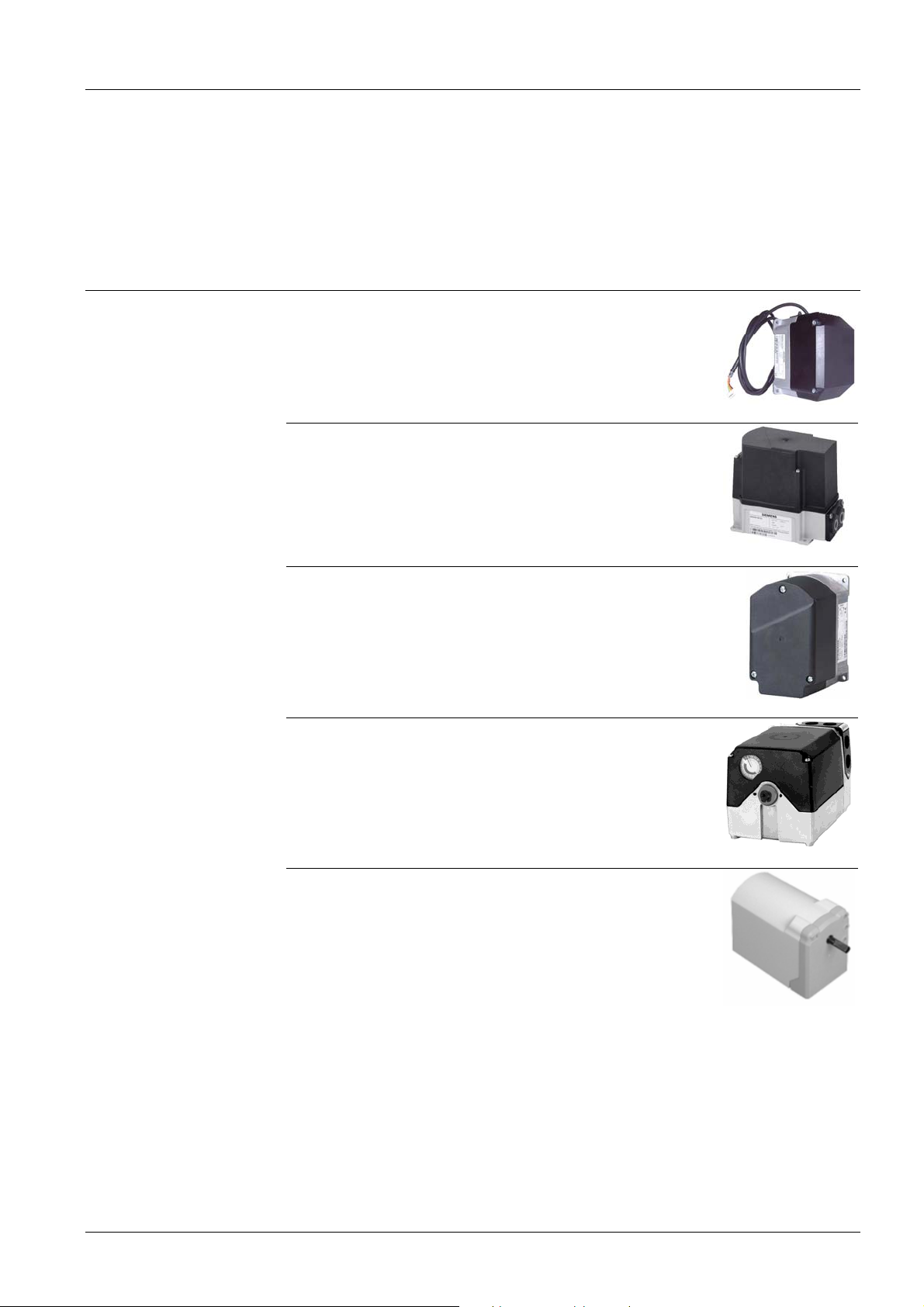
Actuator
SQM33 actuator
(to be ordered separately)
Refer to data sheet N7813
SQM40 actuator
(to be ordered separately)
Refer to data sheet N7817
SQM45 actuator
(to be ordered separately)
Refer to data sheet N7814
SQM50 actuator
(to be ordered separately)
Mounting sets must be ordered separately, see
Accessories – Mounting plate.
Refer to data sheet N7815
SQN7x.xxxxx1 actuator
(to be ordered separately)
Mounting sets must be ordered separately, see
Accessories – Mounting plate.
Refer to data sheet N7802/N7804
5/16
Building Technologies CC1N7673en
25.03.2019

Accessories (continued)
Mounting plate
ASK33.1 mounting plate
Article no: BPZ:ASK33.1
(included in scope of delivery)
Mounting plate for mounting actuators SQM33, SQM40
and SQM45
Note!
The required screws (3x M5 countersunk screws and 4x M5 screws) are included in
the packaging for the ASK33.1.
ASK33.3 mounting plate
Article no: BPZ:ASK33.3
(to be ordered separately)
Larger mounting plate required to replace existing
mounting plate
Required for mounting the actuators SQM5 with AGA58.5.
Note!
The required screws (4x M6x15) are included in the packaging for the ASK33.3.
Drive shafts
ASK33.5 mounting plate
Article no: S55857-Z101-A100
(to be ordered separately)
Mounting plate for mounting the actuator SQN7x.xxxA21
Reducing sleeve included in scope of delivery
Note!
The required screws are included in the standard scope of delivery.
AGA58.5 drive shaft
Article no: BPZ:AGA58.5
For installation in the SQM50 and mounting on the VKF1x
D shaft Ø 10 mm
6/16
Building Technologies CC1N7673en
25.03.2019

Technical data
General unit data
Environmental
conditions
Gas types 1% H2S, 1% NH3 maximum Gas families I…III, air and flue gas
Operating pressure
Up to and including DN100 Max. 150 kPa (1.5 bar)
From DN125 Max. 100 kPa (1 bar)
Mounting positions
7632z01/0103
Leakage rate at VKF11 (internal) Refer to Type summary
Effective rotation angle 85° butterfly valve
Materials
Valve body GGG40.3
Cast iron with nodular graphite
according to DIN EN 1563
Shaft and valve disk Stainless steel
Shaft seal 2 O-rings
No non-ferrous metals
Weight Refer to Dimensions
Storage DIN EN 60721-3-1
Climatic conditions Class 1K3
Mechanical conditions Class 1M2
Temperature range -20…+60°C
Humidity < 95% r.h.
Transport DIN EN 60721-3-2
Climatic conditions Class 2K2
Mechanical conditions Class 2M2
Temperature range -20…+60°C
Humidity < 95% r.h.
Operation DIN EN 60721-3-3
Climatic conditions Class 3K5
Mechanical conditions Class 3M2
Temperature range
VKF10/VK11 -15…+180°C (air and flue gas)
-15…60°C (gas)
Humidity < 95% r.h.
Caution!
Condensation, formation of ice, and ingress of water are not permitted.
7/16
Building Technologies CC1N7673en
25.03.2019

Flow chart
)
00
5
3000
Illustration of the VKF10.032 to VKF10.080, characteristic curve for the effective positioning range (5°…85°)
5
450
400
350
300
250
kv values
200
150
100
50
0
5 1525354555657585
Opening angle in degrees (°
Illustration of the VKF10.100 to VKF10.200, characteristic curve for the effective positioning range (5°…85°)
7673d03en/1018
VKF10.080
VKF10.065
VKF10.050
VKF10.040
VKF10.032
2500
2000
1500
kv values
1000
500
0
5 1525354555657585
Opening angle in degrees (°)
7673d04en/1018
VKF10.200
VKF10.150
VKF10.12
VKF10.100
8/16
Building Technologies CC1N7673en
25.03.2019

Flow chart (continued)
Illustration of the comparison between the VKF10.040 and VKF11.040, lower opening range (5°…25°)
10
kv values
VKF10.040
VKF11.040
9
8
7
6
5
4
3
2
1
0
510152025
Opening angle in degrees (°)
7673d05en/1018
Type Opening angle
5° *) 15° *) 25° *) 35° 45° 55° 65° 75° 85°
VKF10.032 0.6 1.6 2.8 5.6 9.5 15.3 23.7 30.9 33.7
VKF10.040 0.8 2.2 5.1 9.7 16.5 26.4 40.1 60.2 84.1
VKF10.050 0.8 3.0 7.6 15.7 29.0 47.5 74.3 120.3 150.1
VKF10.065 1.5 4.9 12.7 29.4 54.0 83.4 131.0 208.2 249.8
VKF10.080 2.7 9.4 25.4 53.6 87.4 140.9 220.0 325.6 382.9
VKF10.100 3.7 12.0 34.0 65.3 118.9 193.1 308.3 532.4 785.5
VKF10.125 5.9 23.5 69.3 135.8 229.3 350.2 545.6 921.6 1120.1
VKF10.150 6.2 26.0 90.2 182.2 322.9 499.3 767.2 1287.4 1702.4
VKF10.200 9.8 46.9 177.3 320.5 517.7 809.9 1186.8 1813.4 2337.8
VKF11.032 0.2 1.0 2.8 5.6 9.5 15.3 23.7 30.9 33.7
VKF11.040 0.2 1.9 5.1 9.7 16.5 26.4 40.1 60.2 84.1
VKF11.050 0.2 2.6 7.6 15.7 29.0 47.5 74.3 120.3 150.1
VKF11.065 0.3 4.3 12.7 29.4 54.0 83.4 131.0 208.2 249.8
VKF11.080 0.3 9.0 25.4 53.6 87.4 140.9 220.0 325.6 382.9
VKF11.100 0.3 11.4 34.0 65.3 118.9 193.1 308.3 532.4 785.5
VKF11.125 0.3 19.5 69.3 135.8 229.3 350.2 545.6 921.6 1120.1
VKF11.150 0.4 21.3 90.2 182.2 322.9 499.3 767.2 1287.4 1702.4
VKF11.200 0.6 39.2 177.3 320.5 517.7 809.9 1186.8 1813.4 2337.8
*) The characteristic curves follow the same course above 25°
9/16
Building Technologies CC1N7673en
25.03.2019

Flow chart (continued)
Caution!
In the case of burners operating with small low-fire volumes, select a tightly sized valve
If the gas pressure exceeds the maximum permissible operating pressure, reduce the gas pressure with a pressure
controller
The pressure drop (maximum flow characteristic) is based on a fully open valve
Conversion of air flow rate to a corresponding gas flow rate (natural gas)
Basis for scale
Conversion to air (m³/h) from other types of gases:
Abscissa Medium
Volumetric flow “QG” in m³/h
1 Air 1 1
2 Natural gas 0.61 1.28
3 Propane 1.562 0.8
4 City gas 0.46 1.47
QL=
QG
QL = air volume in m³/h that produces the same pressure drop as “QG”.
f
Density ratio “dv” to air Conversion factor
1
f
v
d
10/16
Building Technologies CC1N7673en
25.03.2019

A
A
A
A
Dimensions
Dimensions in mm
DN32...DN50 DN65 DN80 DN100...DN125 DN150 DN200
7673m05/0318
Type DN A BØ CØ E
VKF1x.032 DN32 30 120 72 100 88.9 110 98.4 4xM16 4x1/2 4xM16 4x1/2 158 2.3
VKF1x.040 DN40 30 130 81.5 110 98.4 125 120.7 4xM16 4x1/2 4xM16 4x5/8 162 2.5
VKF1x.050 DN50 30 155 101 125 120.7 145 139.7 4xM16 4x5/8 4xM16 4x5/8 167 2.9
VKF1x.065 DN65 30 165 120 145 139.7 160 152.4 4xM16 4x5/8 8xM16 4x5/8 174.5 3.4
VKF1x.080 DN80 30 195 132.5 160 152.4 180 190.5 8xM16 4x5/8 8xM16 8x5/8 182 3.6
VKF1x.100 DN100 30 220 160 180 190.5 210 215.9 8xM16 8x5/8 8xM16 8x3/4 192 4.3
VKF1x.125 DN125 40 250 190 210 215.9 240 241.3 8xM16 8x3/4 8xM20 8x3/4 229.5 7.6
VKF1x.150 DN150 40 300 216 240 241.3 295 298.5 8xM20 8x3/4 12xM20 8x3/4 242 9.6
VKF1x.200 DN200 40 340 271 295 298.5 - - 12xM20 8x3/4 - - 267 12.8
ISO
E
SME
ER
ISO
*) ER
SME
*) F
ISO
F
SME
Screws
*) Reference circle for installation in one flange size higher
ISO
Screws
G Weight [kg]
SME
Building Technologies CC1N7673en
25.03.2019
11/16

Dimensions (continued)
Dimensions in mm
Installation examples for VKF1x with actuator
VKF10/VKF11 with SQM45 VKF10/VKF11 with SQM50 and ASK33.3/AGA58.5
132
133
119
7673z03/0318
90
140
193
G
Type DN G
VKF1x.032
VKF1x.040
VKF1x.050
VKF1x.065
VKF1x.080
VKF1x.100
VKF1x.125
VKF1x.150
VKF1x.200
DN32 158
DN40 162
DN50 167
DN65 174.5
DN80 182
DN100 192
DN125 229.5
DN150 242
DN200 267
12/16
Building Technologies CC1N7673en
25.03.2019

Dimensions (continued)
90
A
136
A
SK33.1
Dimensions in mm
76 0.15+
)
x
4
(
7
R
Sectional view B-B
22.3 0.1+
122 0.15+
A
14.8 0.1+
50 0.1+
7673m06en/1018
Sectional view A–A
L
Ø
6.5
+
8
6
O
R
K
Ø
50 0.1+
43
14.8 0.1+
4.6 0.1 (2x)+
Ø
22.3 0.1+
5
1
.
0
B
33 0.1+
90° (2x)
7 (2x)
B
90° (4x)
3
13 (2x)
Ø
Ø
Ø
M5 EP nuts (4x)
5.2 (4x)
13/16
Building Technologies CC1N7673en
25.03.2019

Dimensions (continued)
120
1
1
A
SK33.3
Dimensions in mm
105
22.3 ±0.1
7.5
M6.5 (4x)
44.5
5
100 ±0.15
55.5
7.5
50 ±0.1
5
14.8 ±0.1
A
50 ±0.1
LKR Ø68 ±0.1
Ø5.2 (3x)
3
14.8 ±0.1
B
B
x)
4
(
R3
Ø4.8 +0.1 (2x)
Sectional view
A
22.3 ±0.1
Ø7 (2x)
7673m07en/1018
4
5
°
B-B
90°
Ø13 (2x)
Sectional view
Building Technologies CC1N7673en
25.03.2019
A-A
90°
Ø43
Ø14
Ø18
14/16

Dimensions (continued)
A
SK33.5
Dimensions in mm
42
67
14.8 ±0.1
25
Ø68 ±0.15
22.3 ±0.1
Ø4.6 +0.1 (2x)
14.8 ±0.1
R
7
1
(2x
°
0
)
23.3 ±0.1
A
32 ±0.15
Reducing sleeve
A
Ø36
R
9 (2
x)
48 ±0.15
72 ±0.15
Sectional view A-A
M5 EP nuts (4x)
7673m09en/1018
Ø5.2 (x3)
90° (3x)
7.5 -0.1
15 -0.1
Ø16 -0.2
3
25 -0.1
20.5
12 +0.3
Ø8 H8
Ø10 h8
Fase 1x15°
7673m08en/1018
15/16
Building Technologies CC1N7673en
25.03.2019

Dimensions (continued)
A
GA58.5
Dimensions in mm
AGA58.5
25
19.5
17
14
10
8.5
7673m04en/1018
2019 Siemens AG Building Technologies, Berliner Ring 23, 76437 Rastatt, Germany
Subject to change!
16/16
Building Technologies CC1N7673en
25.03.2019
 Loading...