

Page 1
®
Page 2

Preface
CE
This instrument conforms to the provisions of the EU Directive on In Vitro Diagnostic Medical Devices
(98/79/EC) of the European Parliament and the Council of 27 October 1998.
The contents of this manual with all figures, tables and graphics are intellectual property of ELITechGroup.
Unauthorized commercial or non-commercial excerption or copying of contents and use of this manual (in
total or in parts) are strictly forbidden unless the editor gives written permission for it.
This manual was written and produced with the utmost care. However, errors cannot be fully excluded.
ELITechGroup does not take any responsibilities and accepts no liabilities for incidents of any kind that may
occur because of errors in the manual.
All product names mentioned in this manual are registered trademarks.
®
The Viva-E
conformity. This declaration is supplied with each device in a separate file.
Please call Technical Support if you need advice or you have any questions.
has been conceptualized, manufactured and tested in accordance with the declaration of
®
Manufacturer:
ELITechGroup B.V.
also trading as ELITechGroup Clinical Systems
Van Rensselaerweg 4
6956 AV Spankeren
The Netherlands
Telephone: +31 313 430 500
Telefax: +31 313 427 807
e-mail: service.ecsnl@elitechgroup.com
Internet: www.elitechgroup.com
1
Until December 1, 2013 ELITechGroup B.V. was known as Vital Scientific B.V.
Any reference in this manual to Vital Scientific B.V. or Vital should be read as ELITechGroup B.V. or
ELITechGroup Clinical Systems.
1
,
Distributed by:
Siemens Healthcare Diagnostics Products GmbH
European Headquarters
Ludwig-Erhard Str. 12
65760 Eschborn,
Germany
www.siemens.com/diagnostics
In the US:
Siemens Healthcare Diagnostics Inc.
P.O. Box 6101
Glasgow Business Community
Newark, Delaware 19714-6101
USA
1-800-227-8994
www.siemens.com/diagnostics
Viva-E, Syva and EMIT are trademarks of Siemens Healthcare Diagnostics (formerly Dade Behring). All
other trademarks are trademarks or registered trademarks of their respective owners.
Article No.: 6002-380-410 V05
Page 3

®
Contents
1. SAFETY PRECAUTIONS AND POTENTIAL HAZARDS
1.1 General .......................................................................................................................................................1-2
1.1.1 Basic assumptions for risk analysis ...........................................................................................1-2
1.1.2 Operator qualification.................................................................................................................1-2
1.1.3 Service technician qualification ..................................................................................................1-3
1.2 Description of symbols ................................................................................................................................1-4
1.2.1 Symbols on the instrument.........................................................................................................1-4
1.2.2 Symbols in the manual...............................................................................................................1-4
1.3 Hazards.......................................................................................................................................................1-5
1.3.1 Electrical hazards.......................................................................................................................1-5
1.3.2 Mechanical hazards ...................................................................................................................1-5
1.3.3 Sample and reagent arms..........................................................................................................1-5
1.3.4 Lamp ..........................................................................................................................................1-5
1.3.5 Chemical hazards ......................................................................................................................1-5
1.3.6 Biohazard...................................................................................................................................1-6
1.3.7 Operational requirements...........................................................................................................1-6
1.3.8 Transport and storage requirement............................................................................................1-6
1.4 Installation ...................................................................................................................................................1-7
1.4.1 External connections..................................................................................................................1-7
1.4.2 Maintenance...............................................................................................................................1-7
1.4.3 Instrument unused for one month or longer ...............................................................................1-7
1.4.4 Coolant liquid .............................................................................................................................1-7
1.5 Use of materials with the analyzer ..............................................................................................................1-8
1.5.1 Specimens .................................................................................................................................1-8
1.5.2 Reagents and calibrators ...........................................................................................................1-8
1.5.3 Controls...................................................................................................................................... 1-8
1.5.4 Analytical results ........................................................................................................................1-8
2. INTRODUCTION
2.1 The system..................................................................................................................................................2-2
2.1.1 Intended use .............................................................................................................................2-2
2.1.2 System presentation ..................................................................................................................2-2
2.1.3 Computer control........................................................................................................................2-3
2.2 Modules.......................................................................................................................................................2-4
2.2.1 General ......................................................................................................................................2-4
2.2.2 Rotors.........................................................................................................................................2-5
2.2.3 Pipette system ..........................................................................................................................2-5
2.3 Cooling unit ................................................................................................................................................2-6
2.4 External barcode reader..............................................................................................................................2-7
2.5 Installation ...................................................................................................................................................2-8
2.5.1 Installation requirements ...........................................................................................................2-8
2.5.2 Move the analyzer .....................................................................................................................2-8
2.6 Performance and technical data ...............................................................................................................2-9
2.6.1 Performance ..............................................................................................................................2-9
2.6.2 Sample system ..........................................................................................................................2-9
2.6.3 Reagent system ......................................................................................................................2-10
2.6.4 Measurement station ..............................................................................................................2-10
2.6.5 Minimum PC requirements ......................................................................................................2-11
2.6.6 Cooling unit .............................................................................................................................2-11
2.6.7 External barcode reader ..........................................................................................................2-12
2.6.8 Accuracy and precision ..........................................................................................................2-12
2.7 Analyzer technical data (without washing unit or computer) ....................................................................2-13
2.7.1 Dimensions and weight ..........................................................................................................2-13
2.7.2 Power requirements ................................................................................................................2-13
2.7.3 Environmental requirements ................................................................................................... 2-13
2.7.4 Approvals ................................................................................................................................2-13
VITAL SCIENTIFIC B.V. i
Page 4

3. SYSTEM HANDLING BASICS
3.1 Work Preparation ........................................................................................................................................3-2
3.1.1 Use of the manual......................................................................................................................3-2
3.1.2 Parts of the screen.....................................................................................................................3-3
3.1.3 Navigation keys..........................................................................................................................3-4
3.1.4 Emergency halt ..........................................................................................................................3-4
3.1.5 Messages ..................................................................................................................................3-4
3.2 Start the analyzer for the first time ..............................................................................................................3-5
3.2.1 Prepare the analyzer..................................................................................................................3-5
3.2.2 Start the analyzer....................................................................................................................... 3-5
3.2.3 Install the cooling unit ................................................................................................................3-6
3.2.4 Set the reagent rotor type .........................................................................................................3-7
3.2.5 Passwords .................................................................................................................................3-8
3.2.6 System liquid..............................................................................................................................3-9
3.2.7 System parameters .................................................................................................................3-10
3.3 Checklist....................................................................................................................................................3-12
3.3.1 Checklist for routine operation ...............................................................................................3-12
4. BASIC ROUTINE
4.1 Preparing tests ............................................................................................................................................4-2
4.1.1 Methods to enter sample information and select tests...............................................................4-2
4.2 Enter sample data and test requests .......................................................................................................4-3
4.2.1 Request samples screen ...........................................................................................................4-3
4.2.2 Request samples parameters ...................................................................................................4-4
4.2.3 Request samples function keys .................................................................................................4-5
4.2.4 Request samples and assign tests with an external barcode reader ........................................ 4-6
4.2.5 Manually request samples and assign tests ............................................................................4-6
4.2.6 Request (multiple) samples efficiently .......................................................................................4-7
4.2.7 Requesting priority samples.......................................................................................................4-7
4.2.8 Request a test for a reagent blank.............................................................................................4-7
4.2.9 Request a control test ..............................................................................................................4-8
4.2.10 Request a test for calibration ...................................................................................................4-9
4.2.11 View, edit or delete sample requests ........................................................................................4-9
4.2.12 Print a worklist..........................................................................................................................4-10
4.3 Load the sample rotor and start the tests ...............................................................................................4-11
4.3.1 Preparation of samples, dead volume and over sampling ...................................................4-11
4.3.2 Loading pediatric sample cups.............................................................................................
4.3.3 Sample Handling screen ......................................................................................................... 4-12
4.3.4 Sample rotor positions and color codes ...................................................................................4-12
4.3.5 Worklist and color codes ..........................................................................................................4-14
4.3.6 Sample Handling function keys................................................................................................4-15
4.3.7 Load barcoded samples (with external barcode reader)..........................................................4-16
4.3.8 Load samples (without barcodes) ............................................................................................4-16
4.3.9 Load samples with mouse........................................................................................................4-17
4.3.10 Load samples during a sample run ..........................................................................................4-17
4.3.11 Load a reagent blank ...............................................................................................................4-17
4.3.12 Load a control ..........................................................................................................................4-18
4.3.13 Load a calibrator ......................................................................................................................4-18
4.4 Reagent info screen ..................................................................................................................................4-19
4.4.1 Reagent info parameters..........................................................................................................4-19
4.4.2 Reagent info function keys.......................................................................................................4-20
4.4.3 Check and refill reagents .........................................................................................................4-21
4.5 Start and stop the sample run ...................................................................................................................4-22
4.5.1 Start the analysis run ...............................................................................................................4-22
4.5.2 Unload samples .......................................................................................................................4-22
4.5.3 Error and warning messages ...................................................................................................4-23
4.6 Check and validate the results .................................................................................................................4-25
4.6.1 Evaluate results screen...................................................................................................
4.6.2 Sample list................................................................................................................................4-25
®
....4-11
.........4-25
ii VITAL SCIENTIFIC B.V.
Page 5

®
4.6.3 Sample details..........................................................................................................................4-26
4.6.4 Test results...............................................................................................................................4-26
4.6.5 Evaluate results function keys..................................................................................................4-27
4.6.6 Validation of a result.................................................................................................................4-28
4.6.7 Evaluate historic results ........................................................................................................... 4-28
4.6.8 Result details ...........................................................................................................................4-29
4.6.9 Result details function keys......................................................................................................4-31
4.6.10 Information screen for blank/calibration ...................................................................................4-32
4.6.11 Result details for a two reagent kinetic test..............................................................................4-33
4.6.12 Result details for an endpoint test with a reagent blank...........................................................4-35
4.6.13 Result details for a two point test .............................................................................................4-36
4.6.14 Result details for a measurement with a prozone check..........................................................4-38
4.6.15 Automatic results printout......................................................................................................... 4-39
5. EXTENDED ROUTINE
5.1 Program controls ......................................................................................................................................5-2
5.1.1 Introduction ................................................................................................................................5-2
5.1.2 Program control screen..............................................................................................................5-2
5.1.3 Program control parameters .....................................................................................................5-2
5.1.4 Program control function keys ...................................................................................................5-3
5.1.5 Enter a new control ....................................................................................................................5-3
5.1.6 Change a control (e.g. when the batch/lot number has changed) .............................................5-4
5.1.7 Program a control.......................................................................................................................5-5
5.1.8 Westgard rules .......................................................................................................................... 5-7
5.2 Calibrator programming ...........................................................................................................................5-8
5.2.1 Calibrators..................................................................................................................................5-8
5.2.2 Program a calibrator...................................................................................................................5-8
5.2.3 Program calibrator parameters ...............................................................................................5-10
5.2.4 Program calibrator function keys .............................................................................................5-10
5.3 Test programming ..................................................................................................................................5-11
5.3.1 Introduction ..............................................................................................................................5-11
5.3.2 Load the test parameters .........................................................................................................5-11
5.3.3 Program a new test or modify an existing test ........................................................................5-12
5.3.4 Test programming - Test parameters 1 .................................................................................5-14
5.3.5 Test programming - Test parameters 2 ...............................................................................5-18
5.3.6 Program test calibrator parameters ........................................................................................5-25
5.3.7 Program calibrator function keys .............................................................................................5-28
5.3.8 Calibration curves algorithms...................................................................................................5-29
5.3.9 Accept calibration curve parameters........................................................................................5-31
5.3.10 Absorbance check for calibrated tests .....................................................................................5-31
5.4 Quality control ..........................................................................................................................................5-32
5.4.1 Introduction ..............................................................................................................................5-32
5.4.2 Quality control screen ..............................................................................................................5-32
5.4.3 Quality control parameters .....................................................................................................5-32
5.4.4 Quality control function keys ....................................................................................................5-32
5.4.5 Graphic representation of quality control .................................................................................5-33
5.4.6 Fields visible in graphic and table modes (left hand side)........................................................5-33
5.4.7 Description of the graphic display ............................................................................................5-34
5.4.8 Description of the table mode ..................................................................................................5-35
5.5 Cuvette incompatibility ..............................................................................................................................5-36
5.5.1 Introduction ..............................................................................................................................5-36
5.5.2 Start needle and cuvette incompatibility...................................................................................5-36
5.5.3 Incompatibility parameters .......................................................................................................5-36
5.5.4 Incompatibility screen...............................................................................................................5-37
5.5.5 Define incompatible tests.........................................................................................................5-38
5.5.6 Define compatible tests............................................................................................................5-39
5.6 Profiles ...................................................................................................................................................... 5-40
5.6.1 Introduction ..............................................................................................................................5-40
5.6.2 Program profiles ......................................................................................................................5-40
VITAL SCIENTIFIC B.V. iii
Page 6

5.6.3 Program profile function keys...................................................................................................5-41
5.7 Reagent position .......................................................................................................................................5-42
5.7.1 Introduction to reagent position................................................................................................5-42
5.7.2 Program a reagent position......................................................................................................5-42
5.7.3 Reagent position function keys ................................................................................................5-43
5.8 Calculated results ....................................................................................................................................5-45
5.8.1 Introduction to calculated results..............................................................................................5-45
5.8.2 Calculated result programming screen ....................................................................................5-46
5.8.3 Calculated result programming parameters .............................................................................5-46
5.8.4 Calculated result programming function keys ..........................................................................5-48
5.9 Test messages and flags ..........................................................................................................................5-49
5.9.1 Introduction ..............................................................................................................................5-49
5.9.2 Test messages function keys...................................................................................................5-49
5.9.3 Test flags .................................................................................................................................5-50
5.9.4 Custom automatic evaluation and rerun ..................................................................................5-53
5.10 Set up a report ..........................................................................................................................................5-54
5.10.1 Introduction ..............................................................................................................................5-54
5.10.2 Report setup segments............................................................................................................ 5-54
5.10.3 Define a report set-up .............................................................................................................. 5-55
5.10.4 Report setup tabs and data fields ............................................................................................5-56
5.10.5 Report setup function keys.......................................................................................................5-59
®
6. MAINTENANCE
6.1 Maintenance procedures.............................................................................................................................6-2
6.1.1 User maintenance......................................................................................................................6-2
6.1.2 Replace cuvette rotor.................................................................................................................6-3
6.1.3 Manual cuvette rotor blank measurement..................................................................................6-3
6.1.4 Exclude a stained cuvette ..........................................................................................................6-4
6.1.5 Blank rotor function keys............................................................................................................6-5
6.1.6 Replace the photometer lamp....................................................................................................6-5
6.1.7 Replace syringes........................................................................................................................6-8
6.1.8 Washing/filling cuvette rotor .......................................................................................................6-9
6.1.9 Needle rinse.............................................................................................................................6-10
6.1.10 Replace the water filter ............................................................................................................6-10
6.1.11 Replace the drying block..........................................................................................................6-11
6.2 Troubleshooting ........................................................................................................................................6-12
6.2.1 Introduction ..............................................................................................................................6-12
6.2.2 Defective mixer belt..................................................................................................................6-12
6.2.3 Sample needle clogged............................................................................................................6-13
6.2.4 Removal of the rotor tray..........................................................................................................6-13
6.2.5 Error history..............................................................................................................................6-13
6.2.6 Error messages........................................................................................................................6-15
6.2.7 Hardware-error messages .......................................................................................................6-16
7. INSTALLATION
7.1 Hardware installation...................................................................................................................................7-2
7.2 Software installation....................................................................................................................................7-3
7.2.1 General ......................................................................................................................................7-3
7.2.2 Prepare PC ................................................................................................................................7-3
7.2.3 Install software ...........................................................................................................................7-6
7.2.4 Files............................................................................................................................................7-7
7.3 Configure software ......................................................................................................................................7-8
7.3.1 Introduction ................................................................................................................................7-8
7.3.2 Start communication selection ...................................................................................................7-9
7.3.3 Printer parameters ...................................................................................................................7-10
7.3.4 Host communication parameters .............................................................................................7-10
7.3.5 Communication function keys ..................................................................................................7-10
7.3.6 Configure analyzer communication handler.............................................................................7-11
7.3.7 Configure host port settings .....................................................................................................7-12
iv VITAL SCIENTIFIC B.V.
Page 7

7.3.8 Host - PC communication ........................................................................................................7-12
7.4 System backup procedure ........................................................................................................................7-13
7.4.1 Backup files..............................................................................................................................7-13
7.4.2 Start Restore point ...................................................................................................................7-13
7.4.3 Restore point parameters.........................................................................................................7-13
7.4.4 Restore point function keys......................................................................................................7-14
7.5 Data backup procedure.............................................................................................................................7-15
7.5.1 Setup........................................................................................................................................ 7-15
7.5.2 Data backup.............................................................................................................................7-15
7.6 Importing and exporting data ....................................................................................................................7-16
7.6.1 Exporting data..........................................................................................................................7-16
7.6.2 Importing data ..........................................................................................................................7-17
8. RESULTS EXPORT FILE
8.1 General .......................................................................................................................................................8-2
8.1.1 Introduction ................................................................................................................................8-2
8.1.2 Summary of new features ..........................................................................................................8-2
8.2 View or change system parameters (additions) ..........................................................................................8-3
8.3 Export results .............................................................................................................................................. 8-5
8.3.1 Select information and create export files..................................................................................8-5
8.3.2 Automatically create archive and export files.............................................................................8-7
8.4 Archive and search results ..........................................................................................................................8-8
8.4.1 Archive results............................................................................................................................8-8
8.4.2 Search results ............................................................................................................................8-8
8.5 Copy export files or archived results files to a USB drive ...........................................................................8-9
8.6 Networking ................................................................................................................................................8-10
VITAL SCIENTIFIC B.V. v
Page 8

®
vi VITAL SCIENTIFIC B.V.
Page 9

®
1SAFETY PRECAUTIONS AND POTENTIAL HAZARDS
Safety Precautions and Potential Hazards
Safety Precautions and Potential Hazards
VITAL SCIENTIFIC B.V. 1-1
Page 10

®
Safety Precautions and Potential Hazards
1.1 General
Before you start installing and working with the analyzer, you should read the safety precautions and
regulations shown in this chapter. Safety comes first!
The analyzer was designed and manufactured according to modern standards and with regard to
international safety regulations. All possible risks that were known at the time of manufacturing were
taken into account and either eliminated or reduced. Nevertheless, some sources of danger cannot
be eliminated. Please note the following guidelines.
When operating the analyzer all national or international guidelines and regulations must be
observed, as in the normal lab routine. Power supply accessories (cables/plugs) must be installed in
such a way that sources of danger (overheating of cables, short circuit due to incorrect fuse ratings,
loose cables etc.) are eliminated. The user should be aware, that if the analyzer is used in a manner
not specified by the manufacturer, the protection provided by the equipment may be impaired. The
analyzer is supplied without anti-virus software. If you connect the analyzer to a network, make sure
that the network has the necessary protection.
1.1.1 Basic assumptions for risk analysis
Following assumptions are the basis for the risk analysis. It is assumed that:
• The Samples were adequately derived, prepared, handled, and labeled before being loaded
into the device.
• Reagents and calibrators were adequately stored, prepared, handled, and labeled before being
loaded into the device.
• Adequate quality control procedures are observed by laboratory personnel to check the
performance of the analyzing system by adequate use of control material.
• Laboratory personnel involved in operation and handling of the device are adequately trained.
• Laboratory personnel involved in operation and handling of the device are aware of the risks
involved in handling material of human origin (biological hazards) and that correct procedures
are followed to prevent infection.
• Service personnel involved in preventive and corrective maintenance of the device are
adequately trained.
• Service personnel who maintain the device know the risks of biological hazards and follow the
correct precautions.
• Preventive maintenance is performed in accordance with the instructions provided by the User
Manual and the Service Manual.
• Original replacement parts are used in maintenance of the device.
• Original disposables are used in operation of the device.
• Reagents and methods are validated before actual samples are measured.
• Service personnel must follow the instructions to install and check the device.
• Limit checks are correctly implemented and used in the test parameter settings. (absorbance,
reagent blank absorbance, control, calibrator, etc.).
• A rotor blank run is performed once every day before measurements are performed.
• Test results obtained from the instrument are carefully examined by an expert before any further
measures are taken based on the analytical results.
1.1.2 Operator qualification
The analyzer should only be used by qualified and trained personnel, who have taken part in a
special operator training course on the instrument.
For clinical tests, the instrument should be used under the management of a doctor or clinical
inspector.
1-2 VITAL SCIENTIFIC B.V.
Page 11

®
1.1.3 Service technician qualification
To install, maintain and repair the instrument, a service technician has to be trained on the
instrument by the manufacturer or their representative. A service technician is also expected to be
familiar with the normal operation of the instrument as described in the operator manual and the
special operations as described in the Service manual.
Safety Precautions and Potential Hazards
VITAL SCIENTIFIC B.V. 1-3
Page 12
®
Safety Precautions and Potential Hazards
1.2 Description of symbols
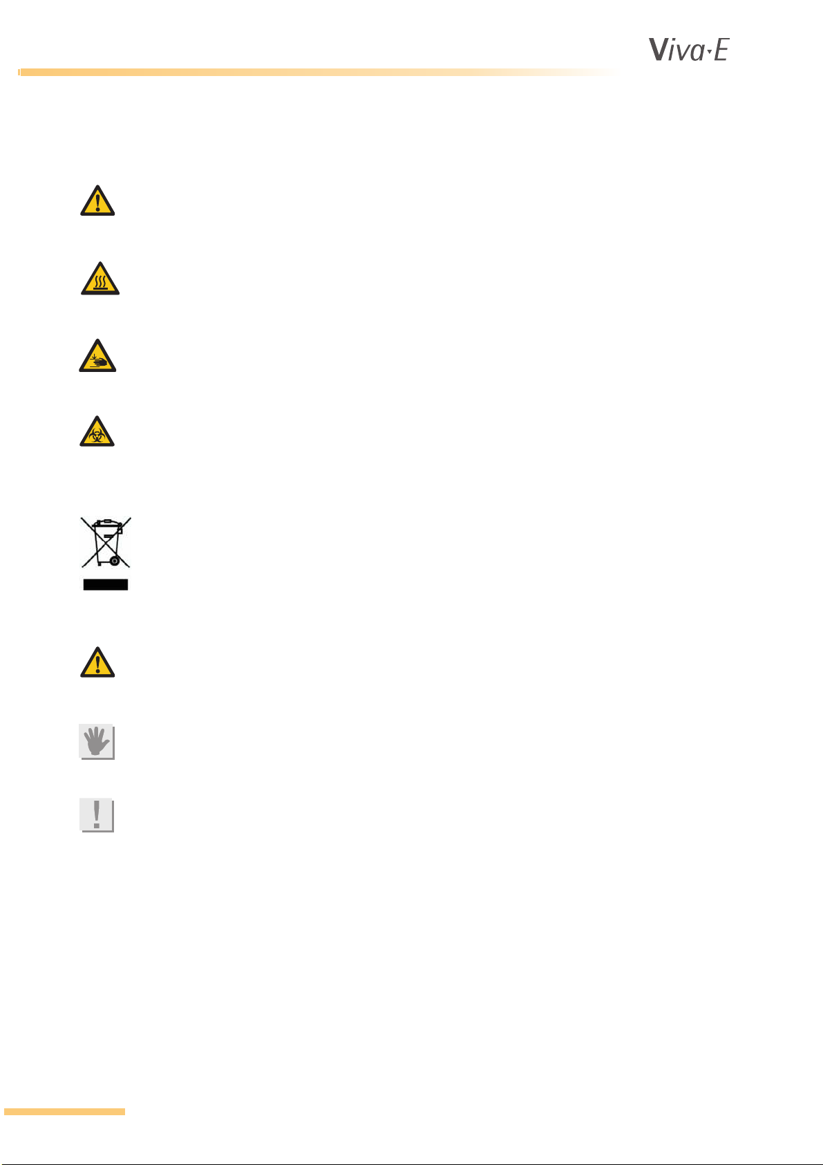
1.2.1 Symbols on the instrument
WARNING
Attention, consult instructions for use. This symbol appears on several parts of the analyzer. The
specific meaning that applies for those parts is described in 1.3 Hazards.
WARNING
Hot surface. This label is attached on or close to parts of the instrument that get hot when the
instrument is switched on. Make sure to keep fingers and other body parts clear of the hot surface.
WARNING
Pinch point. Fingers and other body parts can be pinched where this label shows. Make sure to
keep fingers and other body parts clear of the pinch point.
BIOHAZARD
The contents of the container marked with this symbol are a biological hazard and are potentially
infectious. This symbol is shown on waste bottles.
ATTENTION
This symbol means that at the end of life, the analyzer must be separately collected in accordance
to the European Directive 2002/96/EC.
1.2.2 Symbols in the manual
WARNING
Failure to follow information contained in warning messages could lead to serious personal injury
and/or damage to the analyzer.
ATTENTION
Failure to follow information contained in the attention messages could lead to damage to the
analyzer.
Note
Notes contain additional information corresponding to the text.
1-4 VITAL SCIENTIFIC B.V.
Page 13
®
1.3 Hazards
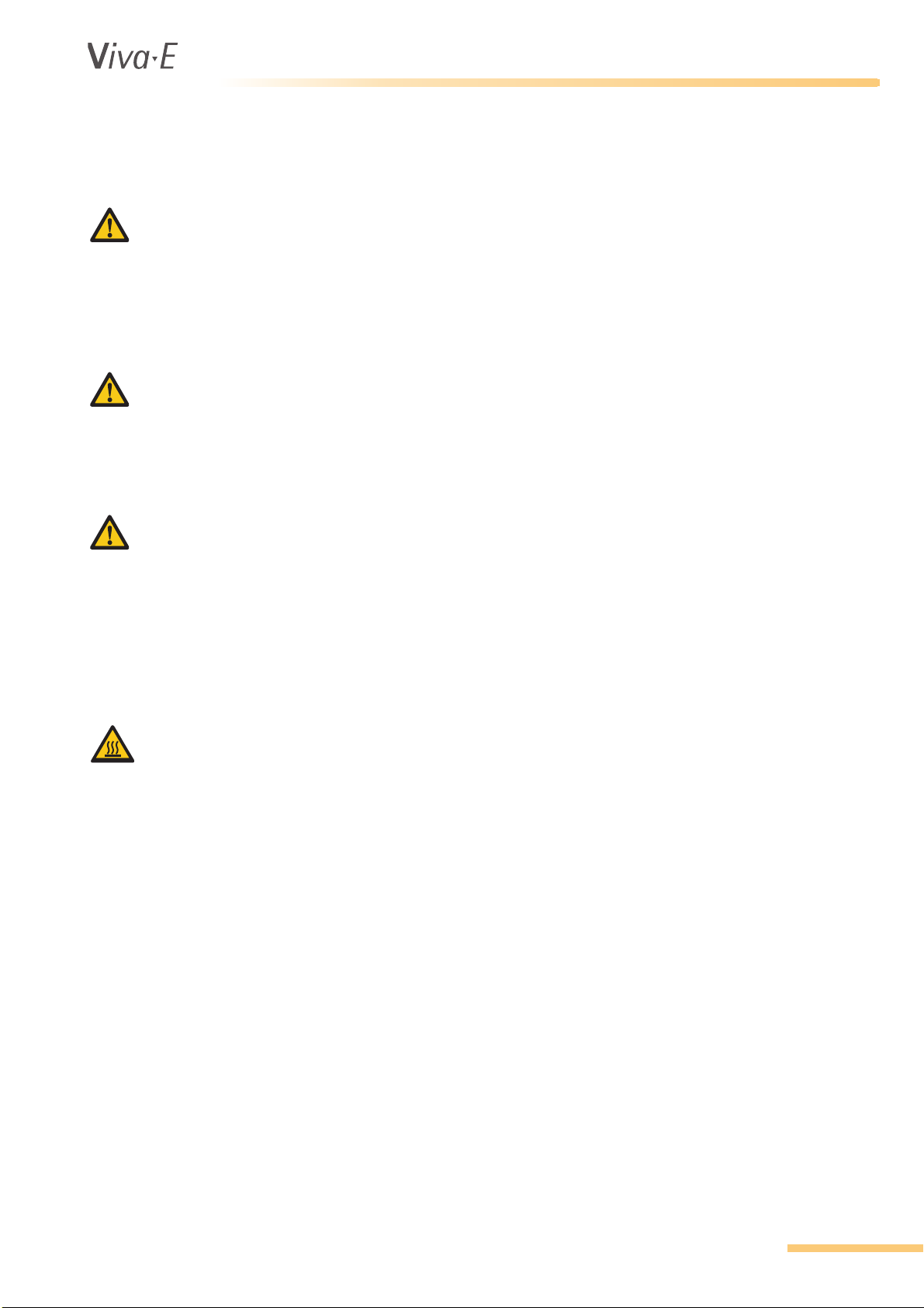
1.3.1 Electrical hazards
WARNING
To prevent the risk of electrical shock and/or damage to the instrument, operators should not open
the covers of live parts (electrical) of the instrument. Only authorized personnel, e.g. service
technicians, may open the instrument to perform maintenance or repairs.
Touching the live parts when the power is on may cause severe injury or death.
1.3.2 Mechanical hazards
WARNING
DO NOT wear loose garments or jewelry that could catch in mechanisms.
DO NOT put your fingers/hands into the pathway of any part while the analyzer is in operation.
DO NOT attempt mechanical repair unless the instrument is not in operation or OFF.
1.3.3 Sample and reagent arms
WARNING
Do not touch movable parts of the system (rotors, arms, etc.) while they are in motion.
Particular attention and caution must be paid to sample and reagent needles. Although the greatest
possible safety precautions were taken, these parts still are potentially hazardous. However, the
system automatically interrupts the procedure if the needles are touched. Always keep rotors
covered with the supplied caps, except when loading or unloading. Covering protects sample
material and reagents from contamination.
Safety Precautions and Potential Hazards
1.3.4 Lamp
WARNING
During operation, the photometric lamp becomes extremely hot. DO NOT look directly into the light
path of the lamp when it is on.
DO NOT touch the lamp when it is on!
If the lamp needs to be changed, wait until the lamp has cooled down.
1.3.5 Chemical hazards
The operator is responsible for taking all necessary precautions against hazards associated with the
use of clinical laboratory chemicals. Specific recommendations for each reagent used with the
analyzer are normally found on the manufacturer's package inserts or on product information sheets
for each chemical. Wipe up any reagent spillage on the instrument immediately.
Additional precautions:
Consult the reagent manufacturer for information on the concentrations of heavy metals and other
toxic constituents in each reagent.
Avoid direct body-contact with reagents and cleaning solutions. Direct body-contact may result in
irritation or damage to your skin. Refer to the manufacturer's reagent kit box and package inserts, or
product information sheets for specific instructions.
VITAL SCIENTIFIC B.V. 1-5
Page 14
®
Safety Precautions and Potential Hazards
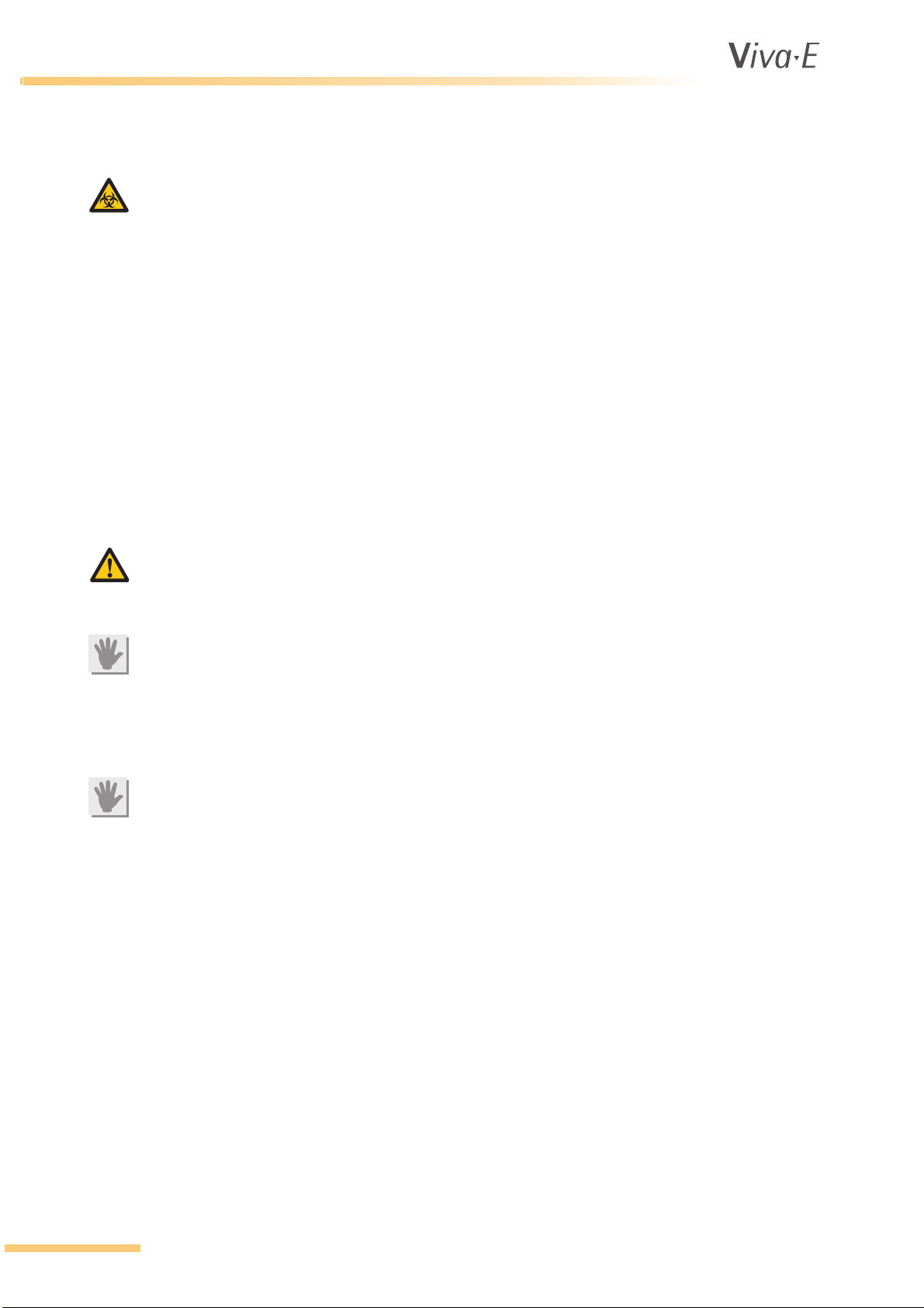
1.3.6 Biohazard
BIOHAZARD
Patient samples, controls, calibrators and liquid waste are potentially infectious. The handling of
patient samples, control sera and liquid waste must be performed according to national and
international laboratory safety regulations.
Patient samples, controls, calibrators and liquid waste should be considered potentially infectious
and capable of transmitting human immunodeficiency virus (HIV), hepatitis B virus (HBV) and other
blood borne pathogens. The handling of these substances must be performed in accordance with
established laboratory safety regulations in order to minimize risk to laboratory staff. This includes
wearing of gloves, splash protection, etc. Contact of skin and mucous membranes must be avoided.
This also applies to all components of the instrument that are exposed to these substances. If any
specimen is spilled on the instrument, wipe it up immediately and clean the contaminated surface
with a disinfectant.
In various countries there are regulations on the disposal of waste. Refer to local sources for
additional information on correct waste disposal.
1.3.7 Operational requirements
WARNING
Do not place the analyzer against a wall. There must be access at all times to the rear panels of the
analyzer. Make sure the power switch can be reached and there is free circulation of ventilation air.
ATTENTION
The cooling unit must be filled with liquid. The level should be visible and between a minimum and
a maximum level. Check liquid level every 3 months. For details on the liquid to be used, see
2.3 Cooling unit.
1.3.8 Transport and storage requirement
ATTENTION
Always store the analyzer in an environment with temperatures between -10 °C and +45 °C.
1-6 VITAL SCIENTIFIC B.V.
Page 15

1.4 Installation
The analyzer, cooling unit and other devices, parts and accessories are shipped in transport boxes
and have to be unpacked and installed by a qualified service technician from the manufacturer or his
designated representative. If these instructions are not observed, The manufacturer does not
assume responsibility for occurring damage or improper operation of the analyzer. The customer is
responsible for providing the necessary facilities as described in detail in 2.6 Performance and
technical data.
1.4.1 External connections
ATTENTION
Only instruments that meet the relevant safety requirements may be connected to the analyzer.
Only use UL-listed power supply cable and power distribution blocks.
1.4.2 Maintenance
ATTENTION
For continued protection against risk of fire only use fuses of the specified type and current ratings.
Safety Precautions and Potential Hazards
For maintenance and repair procedures (e.g. replacement of cuvette rotor, photometer lamp) follow
the instructions given by service personnel or specified in the manual.
Do not use unsuitable tools for repairs (e.g. screwdrivers which are not insulated for work performed
at electrical components).
During operation and maintenance of the instrument, proceed according to the instructions and do
not touch any parts of the instrument other than those specified.
Avoid touching any mechanical parts while the instrument is operating. This may cause operation to
stop or damage the instrument.
Only original spare parts should be used in the maintenance of this analyzer.
Only original disposables and accessories should be used in the operation of this analyzer.
Make sure the front covers are closed while the instrument is in operation.
1.4.3 Instrument unused for one month or longer
If the instrument is not to be used for one month or longer, contact Siemens Healthcare Diagnostics
Technical Support for further information before you switch off the analyzer.
1.4.4 Coolant liquid
The cooling unit of the analyzer is filled with ethylene glycol. Any spills during maintenance should
be disposed of according to local regulations.
VITAL SCIENTIFIC B.V. 1-7
Page 16
®
Safety Precautions and Potential Hazards
1.5 Use of materials with the analyzer
1.5.1 Specimens
This analyzer is designed for measurements of analytes in samples of serum, plasma and urine or
extract solutions from the Siemens immunosuppressant assays. Patient samples should be
prepared and handled in accordance with the instructions from the reagent manufacturer. Refer to
the reagent kit insert for detailed instructions.
ATTENTION
Make sure that the sample/reagent mixture does not contain any blood clots, dust or other insoluble
contaminants. If insoluble contaminants are contained in the sample, correct measuring values may
not be obtained.
1.5.2 Reagents and calibrators
The manufacturer recommends the use of Syva®/Siemens reagents and calibrators in combination
with this analyzer.
ATTENTION
Treat all reagents according the manufacturer's recommendations. Refer to the reagent kit box and
package inserts, and product information sheets for specific instructions.
WARNING
Vital Scientific B.V. assumes no responsibility for erroneous test results caused by reagent kits,
calibrators and test parameters that are not provided by Vital Scientific B.V.
WARNING
Siemens assumes no responsibility for erroneous test results caused by reagent kits, calibrators
and test parameters that are not provided by Siemens.
1.5.3 Controls
The manufacturer recommends the use of quality control solutions with known values for each test
in accordance with international regulations and guidelines. Results obtained should fall within the
limits defined by the day to day variability of the system as determined in the user laboratory. If the
results fall outside the laboratory’s established limits, refer to the troubleshooting information in this
manual or contact your agent.
1.5.4 Analytical results
The analytical results do not only depend upon correct operation of the analyzer but also on a
variety of external influences beyond the control of the manufacturer. Therefore the test results
obtained with this instrument must be carefully examined by a clinical inspector or doctor, before any
diagnostic or therapeutic measures are taken based on the analytical results.
WARNING
An incorrectly measured result may lead to an error in diagnosis, thereby posing a danger to the
patient.
1-8 VITAL SCIENTIFIC B.V.
Page 17

®
2INTRODUCTION
Introduction
Introduction
VITAL SCIENTIFIC B.V. 2-1
Page 18
®
Introduction
2.1 The system
2.1.1 Intended use
The analyzer is an automatic chemistry analyzer, used in combination with certain reagents for in
vitro diagnostic measurement of analytes in samples of serum, plasma, urine and aqueous standard
solutions. Most clinical chemistry tests that require a photometric measurement can be adapted for
the system. The analyzer is intended for use in laboratories. The analyzer has to be operated by
trained operators.
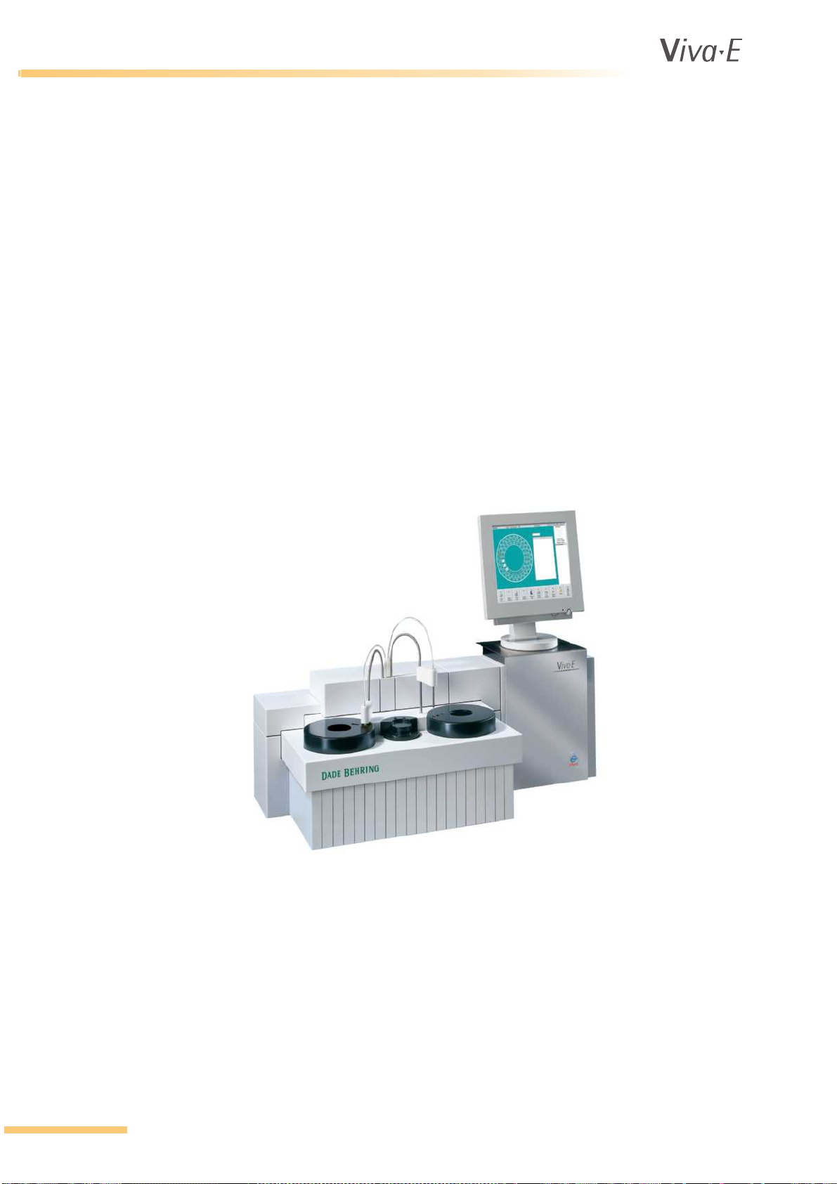
2.1.2 System presentation
The analyzer is a universal system. The price-performance-relation is optimized for small and
medium workload; up to 180 tests per hour. It is easy to adapt the analyzer in any kind of laboratory.
In the main unit of the system, the actual analyzer, all liquid handling and measurements take place.
A separate computer controls the analyzer unit, collects the raw data and provides the user
interface. A cooling unit enables the system to ensure the precision of all ´on-board´ reagents.
Environmental compatibility and economic efficiency are guaranteed. Easy operation (menu and
message control by display), short training time as well as recording of sample and test data with
barcode scanner reduce personnel assignment and save a maximum of time.
2-2 VITAL SCIENTIFIC B.V.
Page 19

®
2.1.3 Computer control
ATTENTION
Only run the software in order to operate the analyzer. The use of other software might cause
failure in the communication between the analyzer and the computer.
An external computer and a monitor provide the user interface for the analyzer. The operating
system is Microsoft
test results are saved on the computer. The software provides a standard way of output on a printer,
but the operator can change the format of the result report. Test parameters, control results and
calibration results are also saved on the computer and are ready for access.
It is possible to connect the analyzer to a lab data processing system (central processor/host
computer). If this is the case, it is possible to enter test requests directly from the host computer.
Also, the test results can be transferred to the host computer.
®
Introduction
Windows®. A keyboard or a barcode reader is necessary to enter data. The
VITAL SCIENTIFIC B.V. 2-3
Page 20
®
Introduction
2.2 Modules
2.2.1 General
Note
In the screen texts system liquid is replaced by water.
The analyzer is microprocessor controlled. All mechanical functions are directed and monitored by
dedicated processors. The operator has a constant view on the hardware status and performance of
the chemistries. When errors or flagged results occur for open channel assays, the analyzer offers
an automatic re-run facility. The re-run facility includes automatic pre-dilution by sample reduction
for high results. The results are printed as the analysis sequence is completed. The print is held
when a test is in evaluation or re-run. This prevents mixing-up the analysis sequence. The operator
can change the format of the result report. Prints of calibration curves, reaction curves, LeveyJennings plots, test methods, etc. are possible.
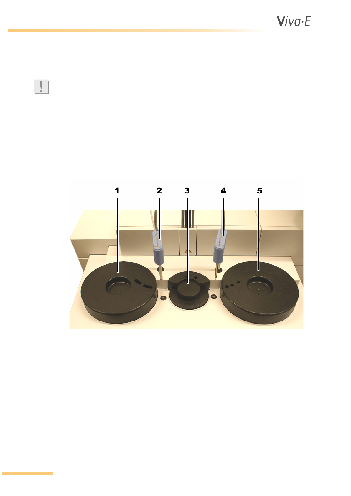
1 Reagent rotor
2 Reagent pipette
3 Cuvette rotor
4 Sample pipette
5 Sample rotor
2-4 VITAL SCIENTIFIC B.V.
Page 21

®
2.2.2 Rotors
Sample rotor
The sample rotor is designed to accept a variety of sample tubes and cups. The sample rotor is
covered. Emergency (STAT) samples and samples in pediatric cups can be tested without
interference of the routine workload.
Reagent rotor
The reagent rotor compartment is cooled to a maximum of 12°C below ambient temperature. The
rotor is covered to protect light sensitive reagents and to isolate from ambient temperature.
Cuvette rotor
Note
Replace the cuvette rotor when one of the eight wavelengths shows the message SD.ERR after the
rotor blank measurement. The quality and reliability is not guaranteed when the cuvette rotor is not
replaced.
The multi-use cuvette rotor contains 48 cuvettes and is incubated at 37°C. The cuvette rotor, made
for the manufacturer, is covered by a heated cover.
The maximum incubation time after sample addition is 11.5 minutes with a single reagent and 11.25
minutes with two or more reagents. After the last measurement, the rotor is washed and dried. To
avoid drying-in of the rotor, the reagent pipette automatically fills the rotor with water.
Introduction
Washing unit
The washing unit aspirates the reaction mixture after analysis and washes the cuvettes with 4 x 500
µl water. The waste is disposed in a waste container. The washing unit is equipped with liquid
sensors to avoid the flooding of the system with water.
2.2.3 Pipette system
Pipettes
Two syringes, a 1000 µl and a 100 µl, are used in combination with a valve block to pipette reagents
and samples. The pipette mechanisms are water-filled. Pipetting takes place by means of positive
water displacement with air bubble separation.
Sample pipette mechanism
The sample probe is equipped with a level detector and can aspirate volumes between 2µl and 30 µl
(in steps of 0.1 µl). The level detector in the sample probe detects if sufficient sample is present. The
probe dispenses the sample into the cuvette rotor and also mixes the reaction mixture. When a
sample is needed, the probe senses the liquid to take up an air bubble first before taking up the
sample. The probe is washed internally and externally afterwards.
Reagent pipette mechanism
The reagent probe is equipped with a level detector and can aspirate volumes between 10 µl and
399 µl (in steps of 1.0 µl). The level detector in the reagent probe detects if sufficient reagent is
present. A heating element in the probe pre-heats the cooled reagents. Reagents must be prepared
outside the analyzer. After the probe transfers the aspirated volume of reagent into the cuvette rotor,
the probe is washed internally and externally. After a 2nd or 3rd reagent is dispensed, the reagent
probe mixes the reaction mixture before it goes to the wash.
VITAL SCIENTIFIC B.V. 2-5
Page 22
®
Introduction
2.3 Cooling unit
WARNING
The cooling unit with the analyzer is filled with ethylene glycol. Any spills during maintenance
should be disposed of according to local regulations.
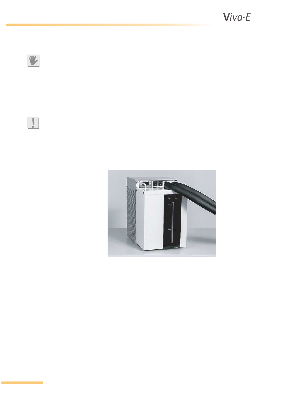
The analyzer is equipped with an external cooling unit that guarantees cooling for loaded reagents.
The cooling unit operates as a sealed unit and needs little maintenance. The cooling unit is placed
behind the liquid waste and water bottles and provides a constant temperature for the reagents
located on the rotor, as required by the application protocol. When an acoustic signal sounds, the
cooling liquid must be refilled.
Note
Use a mixture of 1 part EUROL
The control display shows the temperature of the cooling liquid. The actual temperature of the
reagents will be slightly higher. The user cannot change the temperature setting of the cooling unit.
The unit and coolant are free from chlorofluorocarbons.
The installation is made by the service engineer and is not described in this manual.
®
to 1 part water.
2-6 VITAL SCIENTIFIC B.V.
Page 23
®
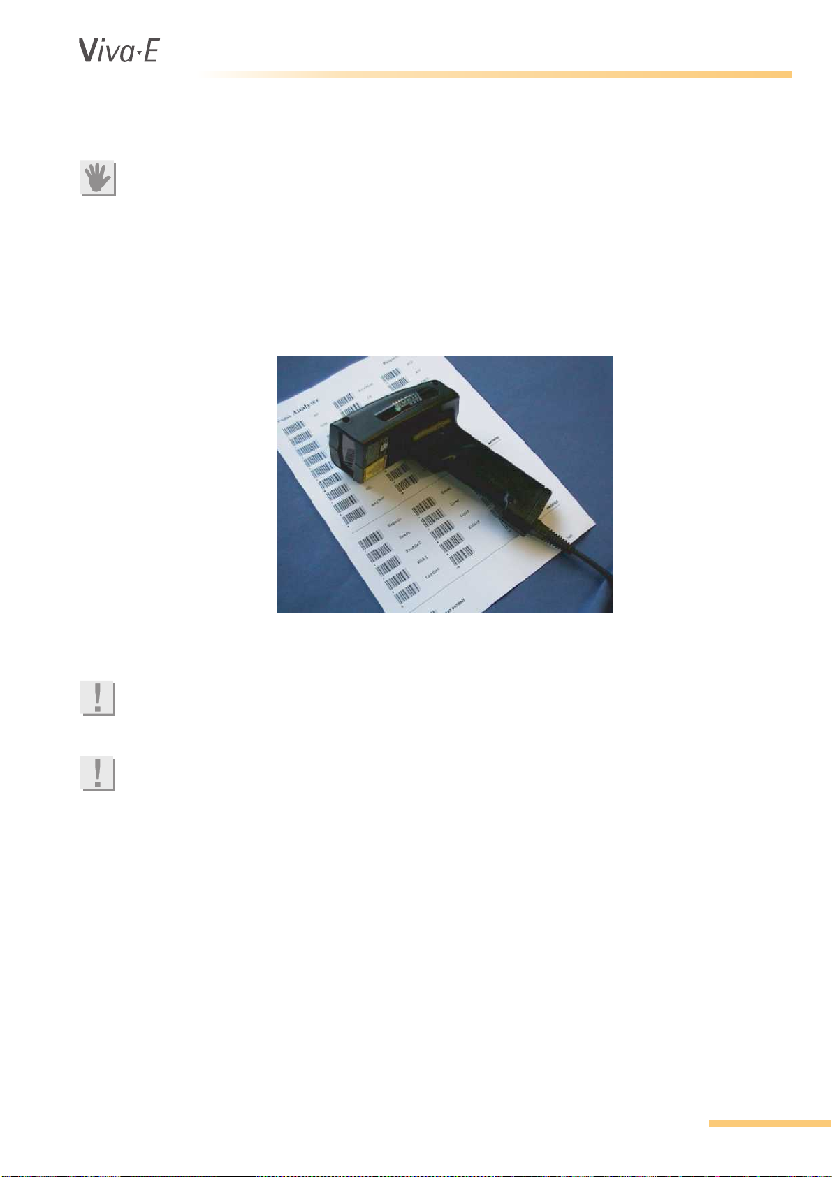
2.4 External barcode reader
ATTENTION
Switch off the computer before you install the external barcode reader.
You can shorten the operator time with an optional external barcode reader. This hand held barcode
reader can be connected to the keyboard of the PC. When requesting tests, you can enter sample
ID numbers from barcodes on the sample tubes. You can then assign tests with the use of the
barcode request menu card.
Most of the available barcodes can be read. The Codabar barcode is used for test requisitions. The
Codabar start character is used to differentiate between tests and profiles.
Introduction
The barcode reader can also be used to identify the samples when loading them or when viewing
the test results.
Note
The external barcode reader has a separate instruction manual. Please read the barcode reader
manual for information and user instruction.
Note
The manufacturer recommends that a fault safe barcode reader is used. Barcode readers that do
not use a checksum can give improper or false readings.
VITAL SCIENTIFIC B.V. 2-7
Page 24

®
Introduction
2.5 Installation
2.5.1 Installation requirements
Only a qualified service technician may unpack the analyzer, cooling unit and other devices. The
manufacturer does not take responsibility for damage or improper operation of the analyzer, when
these instructions are not observed. The analyzer is inspected and ready for use when it is handed
over to the user.
Use the analyzer in closed rooms. It must be placed on a flat, horizontal surface that is not subject to
vibrations. Avoid exposure to direct sunlight.
The electrical connection has to be grounded according to common regulations to ensure proper
operation of the analyzer.
The analyzer is compliant with the requirements of the applicable EMC standards. Electronic
equipment that exceed the radiation limits defined in the EMC standards, like GSM and other
handheld mobile equipment, may affect proper operation of the equipment.
Note
This is a class A product. This product may cause interference in a domestic environment. In this
case the user may be required to take adequate arrangements.
2.5.2 Move the analyzer
Please follow the instructions below when the instrument needs to be moved.
1. Switch off the analyzer, the computer and the cooling unit.
2. Disconnect all cables and tubes.
3. Pull up the arm and place the arm protection tube over the shaft. This prevents the arm from
moving down.
4. Move the analyzer with at least 2 persons. Hold the instrument only by the metal frame on the
bottom.
ATTENTION
Do not lift the instrument by the door that covers the syringes. The door might come off the hinges,
causing the instrument to drop.
5. Connect all cables and tubes again when the analyzer is in place.
2-8 VITAL SCIENTIFIC B.V.
Page 25

®
2.6 Performance and technical data
2.6.1 Performance
Maximum throughput One reagent: 180 tests per hour
Two reagents: 133 tests per hour
Three reagents: 65 tests per hour
Accuracy Refer to 2.6.8 Accuracy and precision
Precision Refer to 2.6.8 Accuracy and precision
Programmable tests 5 per programmed reagent disc
Preprogrammed tests Up to 115
Quality control 1-3 per parameter, 120 controls programmable per reagent rotor
Sample processing Prioritized: STAT, Pediatric, Normal, in that order
Introduction
2.6.2 Sample system
Sample positions 51 patient samples
Emergency samples 3 positions
Calibrators 9 positions plus maximum 51 patient positions
Pediatric samples 6 positions, overflow goes to sample positions 1 - 51
Blank position 1
Controls 4 positions plus maximum 51 patient positions
Rinsing position 1
Sample tubes Primary/secondary tubes
Sample needle With level detector and integrated mixer
Pipetting capacity 2-30 µl (steps of 0.1 µl)
Syringe 100 µl
Diameter: 13 mm
Height: max. 78 mm
Adapter 6 (pediatric, sample rotor)
VITAL SCIENTIFIC B.V. 2-9
Page 26

®
Introduction
2.6.3 Reagent system
Reagent rotor (Emit) 26 positions: 13 x 14 ml, 13 x 28 ml bottles
Volume/test Reagent 1: 110 – 399 µl, reagent 2: 0 – 180 µl,
Cooling Up to 12 °C below ambient temperature
Needle Pre-heated, with level detector
Pipetting capacity 400 µl (steps of 1 µl)
Syringe 1000 µl
Adaptors (Emit) 10 in total: 5 for 6 ml bottle, 5 for 3 ml bottle
2.6.4 Measurement station
Cuvette rotor Multi use disposable rotor with 48 cuvettes
reagent 3: 0 – 180 µl
Path length 6.8 mm
Minimum volume 220 µl
Maximum volume 400 µl
Wash station Fully automatic with overflow-level detector
Cuvette rinsing 4 × 500 µl system liquid
Light source Halogen lamp 12V 20W
Wavelength 340, 415, 505, 546, 570, 600, 660, and 700 nm
Wavelength uncertainty +/- 2 nm
Spectral half-width value 10 +/- 2 nm
Measuring range -0.1 to 3.0 Abs.
Temperature 37 °C ± 0.2 °C
Cycle time 27 sec. (DUAL MODE)
2-10 VITAL SCIENTIFIC B.V.
Page 27

®
2.6.5 Minimum PC requirements
CPU Intel® Pentium® 800 MHz
RAM 128 MB
Monitor VGA monitor 1024 x 768 pixels
Hard Disk 2 GB
Additional drive CD-ROM drive
Operating system Windows
Serial ports 1 required for analyzer, 1 optional for host connection (a LAN
LAN connection Optional for host connection (a serial port can be used instead)
USB Ports One optional for printer
Parallel Ports Optional for printer
®
2000 or Windows® XP
connection can be used instead)
Introduction
2.6.6 Cooling unit
Weight (empty) 19.6 kg
Weight (filled) approx. 23 kg
Required space 84 cm²
Dimensions (cm) 24W × 37H × 35L
Coolant 3.5 liter, glycol-based
System Closed circulation
Connection Mains electrical connector
Power consumption 340 VA max.
At operating voltage 110 or 230 VAC (device-dependent)
Line frequency 50/60 Hz
VITAL SCIENTIFIC B.V. 2-11
Page 28

®
Introduction
2.6.7 External barcode reader
Version Hand device
Technology CCD
Barcodes (standard) Codabar
Barcodes (optional) UPC-A +2, +5
UPC-E +2, +5
EAN-13 +2, +5
EAN-8 +2, +5
Code 39
Code 93
Code 128
Code 2 out of 5
2.6.8 Accuracy and precision
The chemical performance of clinical chemistry analyzers, in terms of accuracy and precision,
depend on the following: the characteristics of the instrument; the measurement techniques and the
materials used. Therefore, the chemical performance characteristics of a clinical chemistry analyzer
can only be established and postulated in terms of: the analyte; the specific reagent kit and
calibrator(s) used; the type and constitution of the specimens involved; etc.
The analyzers are designed as open systems. ´Open´ implies that most clinical chemistry tests and
techniques that require photometric measurement, can be adapted on the system. Only the test
parameters for a specific test need to be adjusted. The user needs to establish the required test
parameter settings to achieve satisfactory results, utilizing appropriate methods. The methods are
preferably based on international guidance documents, for example ECCLS or CLSI guidelines.
The manufacturer does not suggest or propose any particular reagents, calibrators and/or controls
on their analyzers from a specific manufacturer. Obtain information on the performance
characteristics from the selected reagent distributor and/or manufacturer. Various reagent
manufacturers have performed performance studies on these series of analyzers in combination
with their reagent kits. Therefore, they have application sheets available for various analytes. The
required information usually can be obtained from the reagent package inserts. Please contact your
local representative and/or reagent manufacturer for further information on the chemical
performance of their reagents on these analyzers.
Code 2 of 5 interleaved
MSI/Plessey
2-12 VITAL SCIENTIFIC B.V.
Page 29

®
Introduction
2.7 Analyzer technical data (without washing unit or computer)
2.7.1 Dimensions and weight
Width 115 cm
Height 49 cm
Depth 56 cm
Weight approx. 85 kg
2.7.2 Power requirements
Line Voltage 110/240 V nominal, tolerance 10%
Line Frequency 50/60 Hz
Power Consumption 1000VA
Installation category II (in accordance with IEC 664)
2.7.3 Environmental requirements
Ambient temperature 15 to 32 °C
Max. relative humidity 85% @ 32 °C
Pollution degree 2 (in accordance with IEC 664)
2.7.4 Approvals
CE
CB
UL
Note
The approvals listed here refer only to the instrument and operator console, not to additional
devices (cooling). For the approvals for these devices please refer to the corresponding manuals.
VITAL SCIENTIFIC B.V. 2-13
Page 30

®
Introduction
2-14 VITAL SCIENTIFIC B.V.
Page 31

®
3SYSTEM HANDLING BASICS
System Handling Basics
System Handling Basics
VITAL SCIENTIFIC B.V. 3-1
Page 32

®
System Handling Basics
3.1 Work Preparation
WARNING
Read this chapter carefully before you start to work with the analyzer. Always observe the safety
instructions in order to prevent accidents.
Note
In this manual, the dilution ratios are given as parts of the sample to parts of the resultant solution.
Thus, a dilution ratio of 1:5 means 1 part of the sample diluted with 4 parts of diluent that results in
5 parts of solution.
3.1.1 Use of the manual
The Introduction chapter describes the analyzer and its functional modules. The Basic Routine
chapter describes the daily work procedures. The Extended Routine chapter describes less often
used screens, with the parameters and their possible values. Step-by-step procedures are given for
all basic and extended routine operations. Names and values that appear on the screen are shown
in specific fonts and styles to indicate MENU NAMES, FUNCTION KEYS and PARAMETER NAMES.
Example: manually enter sample data and request tests
1. Select F8 REQUEST SAMPLES from the MAIN MENU.
2. Enter the SAMPLE ID:.
3. Enter the other parameters as required or press TAB to go to the tests selection.
4. Select the required tests, profiles and/or calculated results from the TESTS: list.
5. Select F8 NEW SAMPLE to save the sample in the worklist and start the definition of a new
sample.
6. If no more samples are needed, you can proceed to loading samples by pressing F9 SAMPLE
HANDLING.
3-2 VITAL SCIENTIFIC B.V.
Page 33

®
3.1.2 Parts of the screen
System Handling Basics
1. Status line
2. Main screen area
3. Menu Tree
4. Function keys F1 to F10
Status line
The status line shows following information:
• Status of the analyzer, e.g. STAND-BY.
• Request Buffer: information about the number of samples that is requested but not yet loaded.
• Tray Buffer: information about the current number of sample tubes loaded into the analyzer.
• Reagent disc: name of the selected reagent disc.
• Time and Date.
• The state of the external interface (if connected), e.g. HOST.
Main screen area
This area is specific for the menus that can be selected via the menu tree or function keys. The
screens are explained in subsequent chapters.
Function keys
Information of the specific function of the function keys is on constant display on the monitor. All
displays have a common structure with the Function Keys at the bottom of the monitor. You can
press the function keys on the keyboard, or you can click on the button with the mouse.
VITAL SCIENTIFIC B.V. 3-3
Page 34

®
System Handling Basics
3.1.3 Navigation keys
Arrow Keys Go to another field
TAB Switch between left and right fields
PAGE UP/DOWN, HOME, END Scroll through a list
ENTER Select the next field
F1 - F10, SHIFT, CTRL, ALT Go to the associated screen or execute the associated
Spacebar Select or deselect a checkbox and go from left to right
3.1.4 Emergency halt
To halt the analyzer
1. To immediately halt the analyzer, press ALT+F10.
2. The analyzer goes to the inactive state and all in-process measurements are lost.
3. You can repeat these measurements once the analyzer is reset.
function. Function keys can be combined with the Shift,
Ctrl and/or Alt keys to associate more functions to the
same function key.
side tab fields.
To reset the analyzer
1. Select F5 SPECIAL FUNCTIONS from the MAIN MENU.
2. Select F1 ROTOR/SYSTEM.
3. Select F1 RESET SYSTEM to reset the analyzer.
3.1.5 Messages
If an error occurs in the analyzer or the operation routine, the analyzer displays an error message on
the monitor. The message gives information about the error condition and, if possible, instructions
on how to solve the problem. The message is accompanied by an acoustic signal. To turn off the
acoustic signal press the spacebar.
Example:
This message shows when the analyzer liquid is low. You must fill the water container. See the list of
error messages in 6.2 Troubleshooting.
3-4 VITAL SCIENTIFIC B.V.
Page 35

®
3.2 Start the analyzer for the first time
WARNING
Do not install the analyzer yourself. The analyzer must be installed by qualified service technician.
After installation and before you can use the analyzer in normal routine operation, several system
adjustments must be made.
3.2.1 Prepare the analyzer
Do following operations in this sequence:
1. Connect the cooling unit. See 3.2.3 Install the cooling unit.
2. Switch the analyzer on. See 3.2.2 Start the analyzer.
3. Install the password. See 3.2.5 Passwords.
4. Fill the system with system liquid. See 3.2.6 System liquid.
5. Set up the system parameters. See 3.2.7 System parameters.
6. Program the calibrators. See 5.2 Calibrator programming.
7. Load or program the test parameters. See 5.3 Test programming.
8. Program the controls. See 5.1 Program controls.
9. Define the incompatible tests. See 5.5 Cuvette incompatibility.
10. Program the profiles. See 5.6 Profiles.
11. Position the reagents. See 5.7 Reagent position.
System Handling Basics
3.2.2 Start the analyzer
1. Set the main switch to ON. It is located on the rear panel of the analyzer.
2. Set the PC to ON.
3. Start the analyzer software. The MAIN MENU appears on the monitor. When the analyzer
remains on, but is not active carrying out processes, the analyzer goes to STAND-BY mode.
The analyzer starts with a system reset. The analyzer is now ready for operation.
The manufacturer recommends that the analyzer and the user software are switched on at all times.
This makes sure that a cuvette blank is done daily. If the analyzer is switched off, a manual cuvette
blank measurement must be done when you switch on the analyzer again. See 3.2.7 System
parameters.
VITAL SCIENTIFIC B.V. 3-5
Page 36

®
System Handling Basics
3.2.3 Install the cooling unit
The additional external cooling unit of the analyzer guarantees necessary cooling for loaded
reagents. The cooling unit operates with a sealed cycle technology. The cooling unit requires
virtually no maintenance. Unit and coolant are free from CFC.
Fill the unit with coolant and demineralized or distilled water before you put the analyzer in
operation. Only refill the coolant in large intervals, since the coolant circulates in a closed liquid
cycle. Refill the liquid if the LED flashes and/or an acoustic signal is heard.
Note
Use a mixture of 1 part EUROL
ATTENTION
Check the cooling unit for the correct voltage before you connect the cooling unit.
Never let the cooling unit pump run dry, because this will damage the pump.
®
to 1 part water.
1. Attach the connection tubing from the cooling unit to the snap-on connectors of the analyzer, as
indicated in the figure.
2. Install the power cable to the back of the unit. The unit can run with either 110 or 230 V (devicedependent).
3-6 VITAL SCIENTIFIC B.V.
Page 37

®
System Handling Basics
3. Switch on both switches on the front of the cooling unit before you switch on the analyzer.
Recommendations to ensure a steady cooling of the reagent rotor:
• Constantly keep the unit in stand-by mode.
• Cover the unloaded rotor positions with the supplied caps.
3.2.4 Set the reagent rotor type
To use EMIT® tests the reagent rotor type must be set to EMIT. This is the default. To use tests from
other manufacturers the reagent rotor type must be set to CLASSIC. An EMIT
positions for reagent bottles; a classic rotor has 32 positions.
1. Select F5 SPECIAL FUNCTIONS from the MAIN MENU.
2. Select F2 INSTALL
3. Select CHANGE REAGENT DISK.
4. Select F2 NEW REAGENT DISK.
5. Select rotor type EMIT or CLASSIC.
6. Confirm.
®
rotor has 26
VITAL SCIENTIFIC B.V. 3-7
Page 38

®
System Handling Basics
3.2.5 Passwords
An operator level 1 password is used to keep unauthorized persons from altering or deleting
important data. The password is required to delete historic data files, perform functional adjustments
and to restrict access to the INSTALLATION, PROGRAMMING and QUALITY CONTROL menus. A
level 2 password is used to restrict access to servicing functions.
Note
If the operator level 1 password is entered incorrectly, the user can still make adjustments to the
lamp.
Note
The level 2 password is only available to Siemens Healthcare Diagnostics personnel.
No password is required to request tests, load samples or start the measurement.
Changing the level 1 password
1. Select F5 SPECIAL FUNCTIONS from the MAIN MENU.
2. Select F2 INSTALL
3. Select PASSWORDS from the list of functions to the left.
4. If the level 1 password was already defined, type it in the OLD PASSWORD: field.
5. Type the desired level 1 password in the NEW PASSWORD: and CONFIRM NEW PASSWORD:
fields.
6. Press SHIFT+F4 CHANGE LEVEL 1 PASSWORD.
7. Press F10 SPECIAL FUNCTIONS to return to the SPECIAL FUNCTIONS menu.
8. Press F10 MAIN MENU to return to the MAIN MENU.
9. Select F4 LOG OFF.
3-8 VITAL SCIENTIFIC B.V.
Page 39

®
3.2.6 System liquid
To prepare the analyzer for operation, make sure the analyzer has sufficient system liquid.
Filling system liquid
1. Fill the water container with 25 ml of system solution and 10 liters of distilled or de-ionized
water. Use water with a conductivity of less than 30 μS and a microbial count of less than 10
CFU/ml. For transport preparation empty the analyzer liquid container and the waste
container(s).
2. Select F5 SPECIAL FUNCTIONS from the MAIN MENU.
3. Select F1 ROTOR/SYSTEM.
4. Select FILL/EMPTY SYSTEM from the list of functions to the left.
System Handling Basics
5. Press F1 FILL SYSTEM, to start filling the analyzer with system liquid.
6. When the filling is complete, make sure that the tubing (e.g. tubing of sample probe or reagent
probe) is filled with system liquid without large air gaps.
7. If you detect any large air gaps, press F1 to perform another fill system cycle.
Emptying system liquid
Use this menu when you must remove water from the analyzer, e.g. for transport purposes.
1. Remove the system liquid hose from the container.
2. Select F5 SPECIAL FUNCTIONS from the MAIN MENU.
3. Select F1 ROTOR/SYSTEM.
4. Select FILL/EMPTY SYSTEM from the list of functions to the left.
5. Select F2 EMPTY SYSTEM to empty the analyzer for transport.
6. Make sure that there is no system liquid left in the tubing. The status of the analyzer is empty.
7. If necessary, select F2 EMPTY SYSTEM to restart the emptying. The remaining waste must be
removed after the procedure has been completed.
VITAL SCIENTIFIC B.V. 3-9
Page 40

®
System Handling Basics
3.2.7 System parameters
Normally the system parameters are defined once, before the analyzer goes into operation.
However, you can change the parameters whenever necessary.
Viewing and changing system parameters
1. Select F5 SPECIAL FUNCTIONS from the MAIN MENU.
2. Select F2 INSTALL
3. Select SYSTEM PARAMETERS from the list of functions to the left.
4. To change a parameter, use the cursor keys or the mouse to select it. Enter the new value or
choose another value from the listbox. Pressing ENTER selects the next parameter.
Parameters
LANGUAGE: Language used for all screen texts. Changes are effective as soon as
you leave this field.
LABORATORY NAME: The laboratory name is shown on every result printout. The name
can be 32 characters long.
SAMPLE ID AUTO
INCR.:
• YES - Automatically increases the SAMPLE ID: in the REQUEST
SAMPLES menu when pressing the NEW SAMPLE button.
Alphanumeric data is always counted up. The analyzer counts
the sequence e.g. from Az99 up to Ba00.
• NO - Empties the SAMPLE ID: in the REQUEST SAMPLES menu
when pressing the NEW SAMPLE button.
. When using barcoded samples, select NO.
3-10 VITAL SCIENTIFIC B.V.
Page 41

®
System Handling Basics
AUTOMATIC BLANK
TIME:
MAX. CUVETTE BLANK
SD:
The time (hh:mm) at which the analyzer will do a daily automatic
blank measurement of the cuvette rotor. Enter the hours, press
ENTER, enter the minutes and press ENTER again. It is
recommended to do this measurement before the daily routine.
This measurement is only possible when the analyzer is in stand-by
mode at the indicated time. Otherwise, you must perform this
measurement manually.
After the measurement the analyzer prints a list with the following
information:
• Blank date/time.
• Blank results.
• Number of days left before you must calibrate the respective
method.
• Number of days left before you must do the next needle rinse in
the maintenance schedule.
• Number of days left before you must do the next system clean.
• The expiry date for reagents, controls and calibrators.
If you do not perform the cuvette blank measurement, the analyzer
can continue to run but the results can be affected and incorrect. In
case of an expired calibration, the analyzer will use the last
calibration data until a new calibration is performed.
The maximum standard deviation tolerated by the analyzer in a blank
measurement of the cuvette rotor. The recommended value is
0.0200. If this deviation is exceeded, an error message is printed out
together with the rotor blank results.
NEEDLE RINSE
INTERVAL:
ERROR SOUND: A selection of five sounds is available for the analyzer. Press F8
ERROR SOUND
DURATION:
The interval in days, at which you do a needle rinsing.
0: No needle rinsing
1: The rinsing must be done each day
2: The number of days after which rinsing must be done
It is recommended to enter 7 days and to perform the rinsing at the
end of the working week. Activate the NEEDLE RINSE function in the
ROTOR/SYSTEM menu.
PLAY ERROR SOUND to hear the error sound. The default sound is
SOUND 1.
Three error sound duration are available.
• CONSTANT - The error sound plays constantly
• 5 MINUTES - The error sound plays for 5 minutes.
• 20 SECONDS - The error sound plays for 20 seconds.
DISK RESULTS
LOCATION:
Fuction keys
F5 CHANGE DISK RESULTS
LOCATION
F8 PLAY ERROR SOUND Plays the selected sound.
F10 SPECIAL FUNCTIONS Go to the SPECIAL FUNCTIONS menu.
Change the location where historic data files are stored.
Change the location where historic data files are saved.
VITAL SCIENTIFIC B.V. 3-11
Page 42

®
System Handling Basics
3.3 Checklist
3.3.1 Checklist for routine operation
WARNING
Always observe the common safety precautions (rubber gloves, splash-protection).
9 Are all cables correctly
connected to the system?
9 Is the system switched on? Analyzer unit, computer and cooling unit are all
9 Is the cooling unit working
correctly?
9 Are all necessary parameters
defined?
Power cables, tubing to cooling unit, communication
cables, etc. are all connected.
switched on.
Fill the cooling unit correctly with coolant. Install the
tubing of the analyzer unit correctly. Regularly check the
temperature on the cooling unit.
Check the following parameters and settings.
• System Parameters
• Printer Settings
• Host Communications
9 Is the liquid system filled
with system liquid?
9 Are all work helps set as
required?
9 Are all necessary test
parameters programmed?
Fill the liquid system of the analyzer with system liquid,
when the system is put into operation for the first time.
Use the FILL/EMPTY SYSTEM function in the ROTOR/
SYSTEM menu. Check the water container and syringes.
Increase of sample number, automatic rerun, custom
result evaluation, automatic cuvette rotor blank, profiles.
Load or program all parameters that are regularly used
by the analyzer. Use the TEST PROGRAMMING function
in the PROGRAMMING menu. This also applies to new
tests that must be added. The programming instructions
(e.g. test method, volumes, units etc.) are explained in
the method sheets of the reagents.
9 Is HCl installed? HCl must always be present on the reagent rotor to
make measurements possible.
9 Are all reagents correctly
positioned?
9 Are all required calibrators
defined?
9 Are all required test controls
defined?
9 Are the incompatible tests
defined?
9 Are the profiles
programmed?
Reagent positions on the reagent rotor that are
currently used must be programmed in the analyzer.
Use the INSTALLATION menu. To avoid delays in
routine operation, check the volumes of the loaded
reagents before each run (REAGENT INFO menu).
Program the calibrators to be used by the system in the
CALIBRATORS menu.
Program the controls in the CONTROLS menu.
Certain tests must not be run in succession, since the
danger of carry-over is very high. Select the tests not to
be run in succession via the NEEDLE
INCOMPATIBILITY and CUVETTE
INCOMPATIBILITY functions in the PROGRAMMING
menu.
Select the profiles via the PROFILE PROGRAMMING
function in the PROGRAMMING menu, if you want to use
profiles for the ordering of patient samples.
3-12 VITAL SCIENTIFIC B.V.
Page 43

®
System Handling Basics
9 Has the cuvette rotor blank
been done?
9 Has the waste container been
emptied?
9 Has the water container been
filled?
9 Has the formation of foam
been avoided during reagent
preparation?
9 Has the formation of foam
been avoided during sample
preparation?
Perform a cuvette rotor blank measurement once every
day. This measurement is carried out automatically, if
the respective settings have been made in the SYSTEM
PARAMETERS menu. For this purpose, the system has
to be in stand-by mode. Use the BLANK ROTOR function
in the ROTOR/SYSTEM menu for a manual start of the
analyzer blank.
Empty the waste container before you start the daily
work. The analyzer stops the operation if the water level
is too low or the waste water too high. The analyzer
continues again when the required liquids are filled up
or emptied.
Fill the water container before you start the daily work.
This avoids the interruption of the routine work.
Inspect reagent bottles.
Inspect sample tubes.
VITAL SCIENTIFIC B.V. 3-13
Page 44

®
System Handling Basics
3-14 VITAL SCIENTIFIC B.V.
Page 45

®
4BASIC ROUTINE
Basic Routine
Basic Routine
VITAL SCIENTIFIC B.V. 4-1
Page 46

®
Basic Routine
4.1 Preparing tests
4.1.1 Methods to enter sample information and select tests
The analyzer can receive sample information by three methods:
• All test information (sample identification and test requests) can be sent from the host computer
to the analyzer. Refer to your LIS host software supplier for the method to send test information
to the analyzer. The sample tubes must have barcode labels for identification.
The sample tubes loaded with this method can make use of the external barcode reader. No
request list needs to be defined in this case and samples can be loaded immediately. This is
described in 4.3.7 Load barcoded samples (with external barcode reader).
• Sample information can be recorded by an external handheld barcode reader. Barcodes are
read from the sample tubes and/or from a barcodes card that is used to identify samples and
select tests or profiles. This is described in 4.2.4 Request samples and assign tests with an
external barcode reader.
When the worklist is filled, samples must be identified when they are placed in the sample rotor.
This can also be done using the external barcode reader. This is described in 4.3.7 Load
barcoded samples (with external barcode reader).
• Sample information can be manually entered by the user. The samples do not need barcode
labels in this case. Sample IDs and associated test requests are selected via a mouse and/or
the keyboard. This is described in 4.2.5 Manually request samples and assign tests.
When samples do not have barcodes, the position in which they are placed in the sample rotor
is determined by the analyzer software. The method to load the samples is described in
4.3.8 Load samples (without barcodes).
4-2 VITAL SCIENTIFIC B.V.
Page 47

®
4.2 Enter sample data and test requests
4.2.1 REQUEST SAMPLES screen
Basic Routine
The REQUEST SAMPLES screen allows requesting new samples, entering sample data and
assigning tests to the samples. Samples can later be edited or deleted. If needed, the operator can
print a worklist.
Note
The REQUEST SAMPLES screen is also used as a starting point to request priority samples, reagent
blanks, control tests and calibrations. This is done by selecting options in the REQUEST TYPE:
listbox. Procedures for requesting special samples types are described in the following
subsections:
• STAT and PEDIATRIC - See 4.2.7 Requesting priority samples.
• BLANK - See 4.2.8 Request a test for a reagent blank.
• CONTROL - See 4.2.9 Request a control test.
• CALIBRATE - See 4.2.10 Request a test for calibration.
VITAL SCIENTIFIC B.V. 4-3
Page 48

®
Basic Routine
4.2.2 REQUEST SAMPLES parameters
Parameter Description
REQUEST NUMBER A request number is automatically assigned to each sample that is
requested. The request number is shown on the top left. The request
number indicates the place of the sample in the request buffer. An
asterisk indicates a new request that is not saved yet.
REQUEST TYPE: The type of sample that is requested:
• SAMPLE
Patient samples are positioned on the outer two rings of the sample
rotor. The analyzer can process a maximum of 51 patient samples
at one time, without having to reload the sample rotor.
• STAT
Emergency sample. The STAT samples have priority over all other
samples. The analyzer has three positions for emergency samples
(E1...E3). If more than three emergency samples are requested in
the same run, the analyzer positions these samples on the normal
sample positions.
• PEDIATRIC
Pediatric samples have priority over all Normal samples. Pediatric
samples must be placed in one of the positions P1 to P5.
Request type Pediatric is used to assign priority to samples in
pediatric cups and is not related to the age of the patient. When the
results must be evaluated against the pediatric reference limits, you
must select PEDIATRIC for the SEX: field also.
• CONTROL
Requests that are recognized by the analyzer as controls. You can
place controls in the positions C1 to C4 and in any position available
for patient samples.
• CALIBRATE
Calibrate tests, as described in the respective method sheets. You
can place Calibrators in the positions S1 to S9 and in any position
available for patient samples.
• BLANK
One position on the inner ring of the rotor is reserved for the reagent
blank measurement. It is recommended to carry out a daily blank
measurement for methods that require a reagent blank. You must
place a tube that is filled with distilled water or saline solution at this
position.
SAMPLE ID: Enter the sample ID. Twelve characters are available (letters and
numbers). If the option SAMPLE ID AUTO INCR.: in the SYSTEM
PARAMETERS menu was selected, the analyzer automatically
increments the sample ID for each new sample request. Alphanumeric
data is always counted up. If the previous sample ID was 001, the next
will be 002. If the previous sample ID was Az99, the next will be Ba00.
You can also read the sample ID with the external barcode reader
(either from the label on the sample tube, from a request form or from a
barcode card).
If no ID is entered for a sample, it will not be accepted.
PATIENT NAME:* Enter the patient name or any other form of identification for the sample.
Maximum length: 20 characters.
DATE OF BIRTH:* Enter the date of birth of the patient. The date format is defined in the
regional settings in the Windows
4-4 VITAL SCIENTIFIC B.V.
®
control panel.
Page 49

®
Basic Routine
Parameter Description
SEX:* Select the sex of the patient. Use the drop-down list or press M (MALE), F
(FEMALE) or P (PEDIATRIC). The analyzer uses the specified sex to
compare the results to the respective reference ranges defined in the
TEST PROGRAMMING menu. Pediatric is normally used for samples of
children.
PHYSICIAN:* Enter the name of the physician who ordered the sample. The default is
the last entered name. Maximum length 20 characters.
REPEATS: Select the number of times that the sample must be measured.
TESTS: The REQUEST SAMPLES screen shows a variable number of tests,
profiles and calculated results. The number depends on the tests loaded
in the REAGENT POSITIONS fuctions in the INSTALLATION menu.
Select the tests, profiles and/or calculated results required for the
sample. This can be done by pressing the ARROW UP, ARROW DOWN and
ENTER keys, clicking on the checkboxes, or reading a barcode from the
Codabar card with the external barcode reader.
WORKLIST: The worklist shows the requested samples with their sample ID and
patient name. The position column will be filled when the samples are
loaded (as described in 4.3 Load the sample rotor and start the tests).
The highlighted sample is the one for which the request data are listed
to the left. These data can be edited at any time before the tests are
performed.
* Optional. It is not necessary to enter data in these fields to process a sample.
ATTENTION
Do not use a semi-colon (;) symbol in any of the fields. Use of the semi-colon will cause failures in
the communication with the host.
4.2.3 REQUEST SAMPLES function keys
Keys Description
ARROW LEFT/RIGHT Move inside an entry field from one position to the next.
ARROW UP/DOWN Move the cursor to the next or previous field.
TAB Switch between sample fields and tests list.
ENTER
• Select or deselect a test from the test display.
• Moves the cursor from one field to the next.
F1 WORKLIST Prints the worklist (not shown if the worklist is empty).
F2 STAT Mark the currently selected sample as an emergency sample.
F4 REPEAT MODE Switch repeat mode on or off. When repeat mode is on, the text REPEAT
MODE is shown on the screen below the sample fields.
• On: pressing F8 NEW SAMPLE creates a new sample request with
the same test selections.
• Off: pressing F8 NEW SAMPLE creates a new sample request with
all tests cleared.
F5 PREVIOUS SAMPLE Selects the previous sample in the worklist (if available).
F6 NEXT SAMPLE Selects the next sample in the worklist (if available).
VITAL SCIENTIFIC B.V. 4-5
Page 50

®
Basic Routine
Keys Description
SHIFT+F7 DELETE
ONE
ALT+F7 DELETE ALL Delete all samples from the worklist.
F8 NEW SAMPLE Store the current sample in the worklist and clear the screen for a new
F9 SAMPLE HANDLING Go to the SAMPLE HANDLING menu (loading of the sample rotor).
F10 MAIN MENU Return to the MAIN MENU.
Delete the selected sample from the worklist. The numbers of the
following samples in the worklist are changed accordingly.
sample. If the option SAMPLE ID AUTO INCR.: in the SYSTEM
PARAMETERS is switched on, the sample ID will increment automatically.
Otherwise, the sample ID is cleared.
4.2.4 Request samples and assign tests with an external barcode reader
The barcode label identifies the sample ID, so a manual entry of the sample ID is not necessary
when you use an external barcode reader. To use the external barcode reader, the following
conditions must be met:
• The primary tubes or the sample cups must have barcode labels.
• The desired tests must be marked on the request menu card provided by the manufacturer.
1. Select F8 REQUEST SAMPLES from the MAIN MENU.
2. Scan the code on the sample label. The SAMPLE ID: is shown on the screen.
3. Scan the barcodes of the desired tests from the barcode request menu card. The recorded test
requests are highlighted and the checkboxes are marked.
4. Scan the field NEXT SAMPLE to save the sample and clear the fields for the new sample
request.
Note
The barcode on the request chart is of the type Codabar. Do not use the same type Codabar for
labels on samples. The analyzer will not know if you are entering sample data or test requests.
4.2.5 Manually request samples and assign tests
Note
Always enter a sample ID. Sample requests without a sample ID are not accepted. Sample
requests without a test are also not accepted.
1. Select F8 REQUEST SAMPLES from the MAIN MENU.
2. Enter the SAMPLE ID:.
3. Enter the other parameters as required or press TAB to go to the tests selection.
4. Select the required tests, profiles and/or calculated results from the TESTS: list.
5. Select F8 NEW SAMPLE to save the sample in the worklist and start the definition of a new
sample.
6. If no more samples are needed, you can proceed to loading samples by pressing F9 SAMPLE
HANDLING.
4-6 VITAL SCIENTIFIC B.V.
Page 51

®
4.2.6 Request (multiple) samples efficiently
When requesting (multiple) samples, several options are available to speed up the process. These
are explained separately below. All methods can be combined. The basic procedure for requesting
samples does not change when using these methods.
Automatic Sample ID numbering
When the option SAMPLE ID AUTO INCR.: in the SYSTEM PARAMETERS is switched on, the
sample ID is automatically incremented when F8 NEW SAMPLE is selected. Alphanumeric data is
always counted up. If the previous sample ID was 001, the next will be 002. If the previous sample
ID was Az99, the next will be Ba00.
Using profiles
A set of tests can be combined into a test profile. These are listed in bold in the top of the TESTS:
list. When a profile is selected, all tests belonging to that profile are selected in the TESTS: list.
Defining profiles is done via the PROFILE PROGRAMMING function in the PROGRAMMING menu.
Using repeat mode
When the repeat mode is switched on, the test selections from the previous sample are copied to
the new sample when F8 NEW SAMPLE is selected. The repeat mode can be switched on by
selecting F4 REPEAT MODE in the REQUEST SAMPLES menu.
Basic Routine
4.2.7 Requesting priority samples
Note
The PEDIATRIC and STAT samples have higher priority over all normal samples. Request type
PEDIATRIC is used to assign priority to samples in pediatric cups and is not related to the age of
the patient.
Requesting STAT samples
Setting the status of a sample to STAT is done by selecting F2 STAT while entering the sample data
and test requests. You can also select the STAT option from the REQUEST TYPE: listbox.
Requesting pediatric samples
Select the PEDIATRIC option from the REQUEST TYPE: listbox. Also select the PEDIATRIC option
from the SEX: listbox.
Note
The analyzer requires the entry PEDIATRIC at the parameter SEX: for correct reference range and
result evaluations. Results of this sample type are compared to the reference values in the defined
pediatric samples parameters.
4.2.8 Request a test for a reagent blank
1. Select F8 REQUEST SAMPLES from the MAIN MENU.
2. Select BLANK from the REQUEST TYPE: listbox.
3. The list of available tests is shown. This list contains all tests that are defined with a reagent
blank via the TEST PROGRAMMING function in the PROGRAMMING menu. Select the required
tests.
4. Select F8 NEW SAMPLE to save the request in the worklist and start the definition of a new
request or select F9 SAMPLE HANDLING to proceed with loading the reagent blank.
VITAL SCIENTIFIC B.V. 4-7
Page 52

®
Basic Routine
4.2.9 Request a control test
Note
We recommend that you run controls daily. The frequency depends on the respective method,
legislative regulations of your country and the organization that oversees your laboratory.
1. Select F8 REQUEST SAMPLES from the MAIN MENU.
2. Select CONTROL from the REQUEST TYPE: listbox.
3. The list of available controls is shown. This list contains all controls that are defined via the
CONTROLS function in the PROGRAMMING menu.
4. Select the required control. Tests that can be ordered for each control are listed under the
control name. Use the mouse or the arrow and ENTER keys to select or deselect tests.
5. When a control is highlighted, pressing the + button on the numeric keypad (or clicking the
arrow up symbol with the mouse) increases the number of repeats to be performed for the
selected test(s). Pressing the - button (or clicking the arrow down symbol) decreases the
number of repeats.
6. Select F8 NEW SAMPLE to save the request in the worklist and start the definition of a new
request or select F9 SAMPLE HANDLING to proceed with loading the controls.
4-8 VITAL SCIENTIFIC B.V.
Page 53

®
4.2.10 Request a test for calibration
1. Select F8 REQUEST SAMPLES from the MAIN MENU.
2. Select CALIBRATE from the REQUEST TYPE: listbox.
Basic Routine
3. The list of available tests is shown. This list contains all tests that are defined in the REAGENT
POSITIONS menu.
4. Select the required tests.
5. Select F8 NEW SAMPLE to save the request. The worklist shows the calibrators that will be
tested.
6. (Optional) Select F5 PREVIOUS SAMPLE or F6 NEXT SAMPLE to check which calibrators are
allocated to which individual tests.
7. Select F9 SAMPLE HANDLING to proceed to loading the calibrators.
4.2.11 View, edit or delete sample requests
Note
Samples in the worklist can only be edited or deleted if the measurements are not yet started.
1. Select F8 REQUEST SAMPLES from the MAIN MENU.
2. Select F5 PREVIOUS SAMPLE or F6 NEXT SAMPLE to scroll through the worklist. You can also
select a sample directly by clicking on its line in the worklist with the mouse.
3. Select the required sample to view and edit the sample.
4. Select another sample to save the changes.
5. To delete the selected sample, select SHIFT+F7 DELETE ONE. When the sample is deleted
from the worklist, all following samples are moved up and the next sample in the worklist is
selected automatically. To empty the worklist completely, select ALT+F7 DELETE ALL.
VITAL SCIENTIFIC B.V. 4-9
Page 54

®
Basic Routine
4.2.12 Print a worklist
A worklist can be helpful to prepare samples, calibrators and controls.
1. Select F9 SAMPLE HANDLING from the MAIN MENU.
2. Assign sample positions.
3. Select SHIFT+F1 WORKLIST to print the current worklist. The printout shows these data:
• Laboratory name, time and date.
• Sample type: CALIBRATE (S), Reagent BLANK (B), STAT sample (E), PEDIATRIC sample (P) or
CONTROL (C).
• Sample ID.
• Patient name.
• List of requested tests.
Note
Requests that do not have a special sample type designation are normal samples.
4-10 VITAL SCIENTIFIC B.V.
Page 55

®
4.3 Load the sample rotor and start the tests
4.3.1 Preparation of samples, dead volume and over sampling
To guarantee accurate and precise addition of sample, more sample is used than programmed.
A small volume of extra buffer sample is aspirated before each test and each sample. This buffer
sample removes any water that may line the interior wall of the sample probe. The buffer is
discarded to the waste after every pipetting step.
In addition to the sampling buffer there is also a safety residue (dead volume) left in the sample cups
and secondary tubes that cannot be aspirated because the volume is insufficient for the probe to
accurately aspirate the remaining sample. While preparing samples, take this over sampling and
dead volume into account to avoid insufficient sample and interruption to the routine.
The following specifies the over sampling and dead volume specifications that are expected when
the original tubes and cups are used with this analyzer and when the analyzer is properly adjusted.
Over sampling depends on the programmed sample volume. When:
• Sample volume is 2 - 10 µl: excess volume is 5 µl
• Sample volume is 10 - 20 µl: excess volume is 10 µl
• Sample volume is 20 - 30 µl: excess volume is 15 µl
When using pediatric cups with the prescribed pediatric adaptors, the dead volume in these cups is
~100 µl. When using secondary 13 x 75 mm tubes the dead volume in these tubes is ~350 µl.
When using primary tubes no statement can be made about the dead volume because of the
residue of blood cells after centrifugation.
Basic Routine
4.3.2 Loading pediatric sample cups
ATTENTION
Do not use pediatric sample cups without the silver pediatric adapter shown below. Do not use
adapters other than described below.
To ensure correct functioning of the liquid level sensor, pediatric cups must be loaded in the sample
rotor as follows:
1. Insert the pediatric cup into the silver pediatric adapter.
2. Insert the pediatric adaptor with the pediatric cup into the 13 mm sample rotor.
Note
The 13 mm sample rotor may be loaded with:
• Pediatric cup + pediatric adapter.
• 13 x 75 mm sample tube.
VITAL SCIENTIFIC B.V. 4-11
Page 56

®
Basic Routine
4.3.3 SAMPLE HANDLING screen
The SAMPLE HANDLING menu has all functions to load the sample rotor and start to process the
measurement. You can place the programmed samples in any position on the outer two rings of the
sample rotor. You can also load and start STAT samples, controls, calibrators and pediatric samples.
The analyzer shows the current status of the samples.
You can place a new sample in the sample rotor as soon as the processed sample has been
removed. The analyzer will automatically process the new sample. You can use the REAGENT INFO
menu to check the volume in the bottles of the loaded reagents, check the test counter and refill
liquids if necessary.
4.3.4 Sample rotor positions and color codes
The SAMPLE HANDLING menu shows the sample rotor with all positions. A color code shows the
current process status. The right side of the screen shows the worklist.
Note
A hint message with sample information shows if the mouse is moved over the sample position on
the screen.
Sample rotor positions
Position Description
1 - 51 These positions are used for samples.
B This position is reserved for the reagent blank measurement.
You must place a sample tube filled with distilled water or saline
solution in this position if you request a reagent blank.
S1 - S9 These positions are reserved for calibrators. If more positions are
needed, the analyzer will indicate the positions to use.
4-12 VITAL SCIENTIFIC B.V.
Page 57

®
Basic Routine
Position Description
P1 - P6 These positions are primarily reserved for pediatric samples. The
analyzer processes these samples with higher priority.
E1 - E3 These positions are reserved for STAT samples. The analyzer
processes these samples with highest priority.
C1 - C4 These positions are reserved for the controls. If more positions
are needed, the analyzer will indicate the positions to use.
W This position is reserved for the needle rinse solution. The wash
position must contain a sample tube filled with a sufficient
amount of fresh needle rinse solution. We recommend to use
hypochlorite solution. The needle rinse solution cleans the
sample needle after every measurement batch.
Color codes
The following colors are used for sample rotor positions:
Color Description
empty with white border The position is free.
gray The position has not been measured.
orange These positions are reserved for standard solutions. You do not
have to place any calibrators in these positions.
green The sample on this position is processed and the results are
accepted or rejected by the operator.
green with light green border The result is given, but the test request is not finished.
green with orange border The sample on this position is processed but has one of these
faults:
• An error occured during measurement. Test results with
*INFO* exists for this sample.
• A reagent blank is not available. Test results with *INFO*:
WAITING FOR REAGENT BLANK exist for this sample.
• A calibration curve is not available. Test results with *INFO*:
TEST NOT CALIBRATED exist for this sample.
green with white border The position is selected to unload.
black The sample in this position is in process.
yellow The position is registered and the ID of the sample is recognized
by the system.
You must make sure that the positions are loaded with the
samples indicated on screen.
yellow with green border A host query for the sample in this position is pending.
yellow with red border A host query for the sample in this position has not been
answered within the defined timeout period.
VITAL SCIENTIFIC B.V. 4-13
Page 58

®
Basic Routine
4.3.5 Worklist and color codes
The request list shows the order of samples and control requests, as they have been entered via the
host computer or manually in the REQUEST SAMPLES menu. The list shows all other sample types
at the top of the list. You can identify these samples by the corresponding letter.
SAMPLE ID:
(above the worklist)
POS Select the sample with the up and down arrow key or the left
SAMPLE ID
(in the worklist)
Use this field to search and assign a position to a sample with
either the external barcode reader or type the sample ID and
press the ENTER key.
hand mouse button, press ENTER. The next available position on
the sample rotor is reserved for the sample and shown here.
The analyzer shows all samples in the worklist. The requests for
special sample types are listed first.
• B: Blank (1 position)
• S: Standard (9 positions)
• C: Control (4 positions)
• E: Emergency (3 positions)
• P: Pediatric (6 positions)
Subsequently all normal samples and controls are listed in the
order in which they were requested.
NAME The patient name or form of identification for the sample as set in
the REQUEST SAMPLES menu.
Color codes
The following background colors for samples in the worklist are used:
4-14 VITAL SCIENTIFIC B.V.
Page 59

®
Color Description
white The sample is not yet loaded.
yellow The test is requested, but not yet started.
orange This position is reserved (for multilevel calibrations).
dark blue The sample is selected but not yet assigned to a position.
Pressing ENTER assigns the position. In some cases, multiple
lines are selected and assigned as if they were one sample.
4.3.6 SAMPLE HANDLING function keys
Key Description
CTRL+F1 PRINT LOADLIST Prints what is in every rotor position, regardless of status.
SHIFT+F1 WORKLIST Prints a summary of pending test requests.
Basic Routine
F2 SELECTIVE UNLOAD Opens the selective unload menu. See 4.5.2 Unload samples.
F3 START MEASUREMENT Starts to analyze the samples after you have placed all samples in
the sample rotor.
F3 CONTINUE
MEASUREMENT
F4 CONFIRM UNLOAD When samples are ready and show as full green, you can remove
F5 REAGENT INFO This menu is used to check the volume in the bottles of the loaded
F6 QUALITY CONTROL This menu is used to check the results of the quality control.
F7 EVALUATE SAMPLES This menu is used to check and evaluate results.
F8 REQUEST SAMPLES Go to the REQUEST SAMPLES menu.
F10 MAIN MENU Go back to the MAIN MENU.
Starts newly loaded requests or resumes a run that was
interrupted.
them from the sample rotor. Select F4 CONFIRM UNLOAD before
you load a new sample. Samples that have an INFO can not be
unloaded. See also 4.5.2 Unload samples.
reagents, to check the test counter and refill liquids. Do this check
before each run to make sure that there is sufficient reagent for all
requests. This menu is also used to look up the batch number and
expiry dates of calibrators and controls.
VITAL SCIENTIFIC B.V. 4-15
Page 60

®
Basic Routine
4.3.7 Load barcoded samples (with external barcode reader)
If a communication link to a LIS host computer is not available, an external barcode reader provides
an easy, quick and safe alternative to load samples. See 2.4 External barcode reader.
1. Select F9 SAMPLE HANDLING.
2. Scan the label on the sample. Each scanned sample will be shown on the screen. The sample
is labeled with the relevant position number.
3. Place the sample on the rotor position shown on the screen.
ATTENTION
To avoid mistakes, place the sample on the indicated position on the sample rotor as soon as you
have scanned the sample.
4. Repeat steps 2 and 3 for all samples.
5. Select F3 START MEASUREMENT to perform the requested tests.
4.3.8 Load samples (without barcodes)
Note
You do not have to place the samples in the rotor in the same sequence as defined in the REQUEST
SAMPLES menu.
1. Select F9 SAMPLE HANDLING.
2. Select the required sample from the worklist. Samples with a white background have not been
loaded yet.
3. Press ENTER or double-click with the mouse to position the sample. The sample is allocated a
number. The background color for the sample in the worklist changes to yellow to show that the
sample is loaded.
4. Place the sample on the allocated position on the sample rotor.
5. Repeat steps 3 and 4 for all samples.
6. Select F3 START MEASUREMENTto perform the requested tests.
4-16 VITAL SCIENTIFIC B.V.
Page 61

®
4.3.9 Load samples with mouse
1. Select F9 SAMPLE HANDLING.
2. Select the required sample from the worklist.
3. Right-click the sample in the worklist or press the right arrow key.
4. Type the desired position in the SAMPLE POSITION: field. Press the OK button to accept the
position, or press the CANCEL button to cancel positioning the sample.
5. Place the sample on the rotor position.
ATTENTION
To avoid mistakes, place the sample on the indicated position on the sample rotor as soon as you
have entered the sample information.
6. Repeat steps 3 to 5 for all samples.
7. Select F3 START MEASUREMENTto perform the requested tests.
4.3.10 Load samples during a sample run
Samples can be loaded during a sample run in an emergency. If the sample is a STAT sample, it will
be measured immediately.
1. Select F8 REQUEST SAMPLES.
2. Select request type STAT.
3. Enter the sample data and request the tests for the new sample.
4. Select F9 SAMPLE HANDLING.
5. Select the new sample in the worklist.
6. Press ENTER or double click with the mouse to position the sample. The sample is allocated a
number. Alternatively, you can right-click the sample or press the arrow right key and enter the
desired position number in the dialog that opens.
7. Place the patient sample in the allocated position on the sample rotor.
Basic Routine
ATTENTION
Make sure that the sample pipetting arm is not touched when placing the sample. The best moment
to load a sample during the run is when pipetting has just taken place.
4.3.11 Load a reagent blank
Note
If reagent blanks are required, they should be performed before testing a calibrator.
Note
The reagent blank must first be requested in the REQUEST SAMPLES menu. See 4.2.8 Request a
test for a reagent blank.
1. Select F9 SAMPLE HANDLING.
2. Select BLANK from the worklist.
3. Press ENTER or double click with the mouse to position the blank. The small b changes to a
capital B.
4. Place a sample tube with distilled water or saline solution on position B on the sample rotor.
5. Select F3 START MEASUREMENT.
VITAL SCIENTIFIC B.V. 4-17
Page 62

®
Basic Routine
4.3.12 Load a control
Note
The control must first be requested in the REQUEST SAMPLES menu. See 4.2.9 Request a control
test.
1. Select F9 SAMPLE HANDLING.
2. Select the required control from the worklist.
3. Press ENTER or double click with the mouse to position the control. The small c changes to a
capital C + number. If more positions are needed, the analyzer uses any available position.
4. Place the control in the position indicated on the sample rotor.
5. Select F3 START MEASUREMENT.
4.3.13 Load a calibrator
Note
The calibrator must first be requested in the REQUEST SAMPLES menu. See 4.2.10 Request a test
for calibration.
1. Select F9 SAMPLE HANDLING from the MAIN MENU.
2. Select the required calibrator from the request list.
3. Press ENTER or double click with the mouse to position the calibrator. The small S changes to a
capital S + number. If more positions are needed, the analyzer uses any available position.
4. Place the calibrator in the position indicated on the sample rotor.
5. Select F3 START MEASUREMENT.
4-18 VITAL SCIENTIFIC B.V.
Page 63

®
4.4 REAGENT INFO screen
The REAGENT INFO menu shows the loaded reagents, estimated volumes, batch no and expiry
date. Use this menu to check the reagent inventory before you start the analysis run. We
recommend to check the reagent before the start of each run. When there is not enough reagent
present to finish the request, the analyzer shows there is insufficient reagent. You can refill the
bottles without interruption of the routine during the analysis run.
Note
When a classic rotor is used, the screen shows 32 positions, when an EMIT rotor is used the
screen shows 26 positions.
Basic Routine
4.4.1 REAGENT INFO parameters
Parameter Description
POS The position of the reagent on the reagent rotor.
NAME The name of the reagent. The field also shows the order of the
reagent. R2 shows the reagent is the second reagent. R3 shows
the reagent is the third reagent.
BATCH NO. The batch number of the reagent.
EXPIRY DATE The expiry date of the reagent. The expiry date is the last day of
on-board stability.
ML The available reagent volumes in the bottles.
TESTS
(only in normal mode)
VITAL SCIENTIFIC B.V. 4-19
The number of tests, which can still be processed with the
available volume of the reagent.
Page 64

®
Basic Routine
Parameter Description
TRAY
(only in normal mode)
FILL
(only in normal mode)
TOTAL TEST COUNT
(only in counter mode)
The number of tests that is currently requested.
A red dot shows a shortage of the reagent and a refill is
necessary. A yellow dot shows there is not enough reagent to
perform all the requested tests.
Refill the reagent bottle or delete the test requests as necessary.
The number of tests that have been performed with the reagent
since the last time the count was reset. Resetting all counters is
done by selecting ALT+F3 CLEAR ALL COUNTERS.
4.4.2 REAGENT INFO function keys
Key Description
F1 PRINT Prints a list with the reagent information.
F2 CONFIRM REFILL ALL Confirm that you have refilled all the reagents.
ALT+F3 CLEAR ALL
COUNTERS
(only in counter mode)
F4 CONFIRM REFILL Confirm that you have refilled selected reagents.
Sets all values in the total test counts to zero.
F5 COUNTER MODE
(only in normal mode)
F5 NORMAL MODE
(only in counter mode)
F6 CALIBRATORS AND
CONTROLS
F7 EVALUATE SAMPLES Go to the EVALUATE RESULTS menu.
F8 REQUEST SAMPLES Go to the REQUEST SAMPLES menu.
F9 SAMPLE HANDLING Go to the SAMPLE HANDLING menu.
F10 MAIN MENU Go to the MAIN MENU.
Switch to counter mode.
Switch to normal mode.
Shows the loaded calibrators and controls with their names,
batch numbers and expiry dates.
4-20 VITAL SCIENTIFIC B.V.
Page 65

®
4.4.3 Check and refill reagents
1. Select F9 SAMPLE HANDLING.
2. Select F5 REAGENT INFO.
3. Check the following information:
• The batch in the BATCH NO. column.
• The expiry date in the EXPIRY DATE column.
• The available reagent volume in the ML column.
• Number of the test that can be processed in the TESTS column.
• Number of tests requested in the TRAY column.
Note
The volume of the reagent is measured at the moment the reagent is pipetted. The volume and
test estimates are a guideline to assist the operator and should not be considered an accurate
measurement.
4. Refill reagents if required. You can either refill only the insufficient reagents or refill all reagents:
A Refill insufficient reagents: these are the ones showing the red dots. Select F4 CONFIRM
REFILL after refilling.
B Refill all reagents. Select F2 CONFIRM REFILL ALL after refilling.
Basic Routine
Note
The analyzer assumes that reagents are filled to the bottle volume. The calculation of the
number of tests that can be performed with the remaining reagent is based on this.
5. Select F6 CALIBRATORS AND CONTROLS. to check the batch number and expiry dates of the
calibrators and control samples.
VITAL SCIENTIFIC B.V. 4-21
Page 66

®
Basic Routine
4.5 Start and stop the sample run
4.5.1 Start the analysis run
The analysis run must start from stand-by mode.
1. If the F3 START MEASUREMENT button is not present, the analyzer is in an inactive or halted
state. To change to stand-by mode do as follows:
ASelect F5 SPECIAL FUNCTIONS from the MAIN MENU
BSelect F1 ROTOR/SYSTEM
CSelect F1 RESET SYSTEM
Note
When the analyzer starts from stand-by mode, the analyzer will switch on the lamp and the vacuum
pump, and rinse the cuvettes. Messages will inform you if there are any unusual incidents.
2. Optionally select CTRL+F1 PRINT LOADLIST.
3. Select F3 START MEASUREMENT.
Note
Messages will inform you if the measurements cannot be performed or completed. The most
common messages are explained in 4.5.3 Error and warning messages.
4.5.2 Unload samples
Note
Only finished samples can be unloaded. They are shown on the rotor image by a solid green color.
When moving the mouse over these samples, the status READY FOR UNLOAD appears.
Select F2 SELECTIVE UNLOAD from the SAMPLE HANDLING menu. The SELECTIVE UNLOAD
menu is where you can select samples to be unloaded. Selection is done by the mouse or the
keyboard.
Note
If you want to unload all samples that have status READY FOR UNLOAD, you can do this
immediately from the SAMPLE HANDLING screen. Remove the samples from all positions that are
shown as solid green on the sample rotor and select F4 CONFIRM UNLOAD.
Note
After unloading a sample, you can immediately load a new sample at that position on the sample
rotor. If you Select F3 START MEASUREMENT, the new sample is integrated into the current run
and will be processed.
You have different options to unload one or more samples:
1. Unload one sample at a time.
A Type a sample number in the SAMPLE POSITION: field inside the rotor image and press
ENTER to select the sample for uloading. Instead of this, you can use the mouse to click on
a sample on the rotor image. A white colored ring appears around the green sample.
B Remove the sample tube from the rotor.
C Repeat steps A and B for all individual samples you want to unload.
DSelect F3 CONFIRM UNLOAD to confirm that the samples were unloaded. The rotor
positions for the selected samples are emptied.
2. Unload a range of samples.
ASelect F5 SELECT SERIES.
4-22 VITAL SCIENTIFIC B.V.
Page 67

®
B Type the start position in the START POSITION: field.
C Type the end position in the END POSITION: field. Press ENTER. The samples that are
ready to unload (solid green) in the selected range are marked with a white border.
D Remove the sample tubes from the rotor. Only remove the samples from positions that are
marked with a white border.
ESelect F3 CONFIRM UNLOAD to confirm that the samples were unloaded. The rotor
positions for the selected samples are emptied.
3. Unload all samples
ASelect F4 SELECT ALL. The samples that are ready to unload (solid green) in the entire
rotor are marked with a white border.
B Remove the sample tubes from the rotor. Only remove the samples from positions that are
marked with a white border.
CSelect F3 CONFIRM UNLOAD to confirm that the samples were unloaded. The rotor
positions for the selected samples are emptied.
4.5.3 Error and warning messages
If the requested tests cannot be performed, due to insufficient reagent volumes or invalid controls or
calibrations, a dialog window is shown on the screen. The window contains buttons that lead to
further actions. Some of the warnings are described below. A list of all test-related messages is
given in 6.2.6 Error messages.
Basic Routine
Test(s) not calibrated
Key Description
F4 ABORT The measurement is not started. You can return to the F5
REQUEST CALIBRATION menu to change test assignments.
F5 REQUEST CALIBRATION The required calibrations are added to the worklist and selected
automatically. Press the ENTER key to assign positions to the
calibrators and load them in the designated positions on the rotor.
When measurement is continued, the calibrators are measured
first.
SHIFT+F6 CONTINUE The tests are performed and the samples for which non-calibrated
tests are requested will receive an *INFO* status. This can be
viewed via the EVALUATE RESULTS menu.
VITAL SCIENTIFIC B.V. 4-23
Page 68

®
Basic Routine
Insufficient reagent(s)
Key Description
F2 REAGENT INFO The instrument goes to the REAGENT INFO screen. The
instrument stops pipetting the reagent for the test with insufficient
reagent. All other tests continue as normal. The system goes to
stand-by mode when all other tests are complete.
F4 ABORT The measurement is not started. You can return to the REQUEST
SAMPLES menu to change test assignments.
SHIFT+F6 CONTINUE The tests are performed and the samples for which non-calibrated
tests are requested will end with an Info status. This can be
viewed in the EVALUATE RESULTS menu.
Various hardware-related errors
Key Description
F6 SOFT RESET The low-level component that is in an error condition is reset. If
the problem is solved by this, the error message will disappear.
F5 HARD RESET A higher-level component is reset. This also resets the lower-level
components that are contained in it. If the problem is solved by
this, the error message will disappear.
SHIFT+F6 RESET SYSTEM The entire system is reset. If the problem is solved by this, the
error message will disappear.
ALT+F10 HALT The system is halted. Have a service engineer check the cause of
the error condition. See 6.2.7 Hardware-error messages.
4-24 VITAL SCIENTIFIC B.V.
Page 69

®
4.6 Check and validate the results
4.6.1 EVALUATE RESULTS screen
The results of each test can be viewed in the EVALUATE RESULTS screen. The screen contains
three areas of information about the samples and test results. These are described in detail in
separate subsections.
Basic Routine
1. Shows all available samples - see 4.6.2 Sample list.
2. Shows information about the selected sample - see 4.6.3 Sample details.
3. Shows results for the selectd sample - see 4.6.4 Test results.
Depending on the type of test, you can view the calculated absorbances in tabular or graphic format.
This is done in the RESULT DETAILS screen. See 4.6.8 Result details.
4.6.2 Sample list
Column Description
TYPE Type of the sample: Normal, STAT, Pediatric, Blank, Control or
POSITION Position of the sample on the rotor.
SAMPLE ID The ID of the sample.
NAME The name of the patient (if available).
Calibrator.
VITAL SCIENTIFIC B.V. 4-25
Page 70

®
Basic Routine
4.6.3 Sample details
Item Description
SAMPLE ID: The ID of the sample.
PATIENT NAME: The name of the patient (if available).
DATE OF BIRTH: The patient's date of birth (if available).
SEX: The sex of the patient: MALE , FEMALE or PEDIATRIC.
PHYSICIAN: The name of the physician in charge (if available).
MEASUREMENT DATE: The date and time of the test.
SAMPLE TYPE: Type of the sample: Normal, STAT, Pediatric, Blank, Control or
STATUS The current processing status of the sample is shown in the
Calibrator.
status field directly under SAMPLE TYPE:. The status field
shows the position and the status of the samples on the sample
rotor. The following status indications are possible:
• IN PROCESS
The sample or one of its allocated tests is currently being
processed. The result of at least one test is pending.
• UNLOADED
The sample is unloaded.
• READY
The sample has been processed. The results are available.
• WAITING
(List reason for waiting)e.g. Sample is waiting for a valid
calibration.
Rotor position The rotor position of the sample (shows next to the status field, if
4.6.4 Test results
The tests performed for the selected sample are listed together with the measurement results and
units.
Column Description
TEST NAME The name of the test as defined in the test parameters.
RESULT The word *INFO* next to test name indicates that you must
UNITS The units of measure (e.g., mg/dL, U/L) as defined in the test
the sample is still loaded).
validate the result. Press F3 to accept the result, F4 to reject the
result, F5 to repeat the measurement or F6 to re-run the test with
specific re-run volumes. A + sign indicates a tree view of the
data.
parameters.
4-26 VITAL SCIENTIFIC B.V.
Page 71

®
4.6.5 EVALUATE RESULTS function keys
Key Description
F1 PRINT Print a report for the currently selected sample.
Basic Routine
SHIFT+F1 PRINT WITH
R.S.
SHIFT+F2 ARCHIVE
RESULTS
ALT+F2 VIEW HISTORIC
RESULTS
F3 BLANK/CALIB INFO Go to the BLANK/CALIB INFO menu.
SHIFT+F4 MEASURE RERUN Rerun all measurements for the selected sample. The volumes
ALT+F4 MEASURE AGAIN Repeat all measurements for the selected sample. The volumes
F5 ORDER REMEASURE Remeasure all available samples with a specific condition:
Print a report for the currently selected sample using a custom
report setup. See 5.10 Set up a report.
Saves the results to the historic data location defined in the
system parameters..
Displays archived results located in the historic data location.
that are used for the repeated measurement are the volumes
that were defined in the field RERUN VOLUME: of the test
parameters. Remeasurements start immediately.
that are used for the repeated measurement are identical to
those that were originally used. Remeasurements start
immediately.
• REMEASURE INFOS - all samples with *INFO* status.
• REMEASURE REJECTS - all samples with REJECT status.
• REMEASURE POSITIVES - all samples with POSITIVE
status.
When the analyzer is connected to a LIS:
• use F5 ORDER REMEASURE to remeasure all samples with
*INFO* status.
• samples with REJECT or POSITIVE status must be
reordered using the LIS.
F6 QUALITY CONTROL Go to the QUALITY CONTROL screen.
F7 RESULT DETAILS Shows results details screen for the selected sample.
See 4.6.8 Result details.
F8 REQUEST SAMPLES Go to the REQUEST SAMPLES screen.
F9 SAMPLE HANDLING Go to the SAMPLE HANDLING screen.
F10 MAIN MENU Go to the MAIN MENU.
VITAL SCIENTIFIC B.V. 4-27
Page 72

®
Basic Routine
4.6.6 Validation of a result
If the parameter CUSTOM AUTOMATIC EVALUATION: was selected in the CUSTOM EVALUATION
menu, the results are automatically accepted or rejected. If you did not select this parameter, only
results that are outside the limits of the test have to be manually evaluated. Subsequent samples
are printed after one minute when the previous sample needs manual evaluation.
In the EVALUATE RESULTS screen you can check and, if necessary, validate results of a sample
that is currently being processed.
You can check the test results of a sample, view the points in the graph or compare the individual
values of the absorbances. Click on the list and type the ID or use the external barcode reader.
The left screen shows all sample data, the position of the sample on the sample rotor and the status.
You can also view in graphic mode. Select one of the processed tests on the left with the cursor
keys. A graphic of the corresponding test is shown.
When *INFO* is shown next to the test you must validate the results. The sample will not be
released and the analyzer does not print its measurement report.
Sample information (number, name, etc.), test name and unit are shown above the table or the
graphic. A message indicates why the test was not released. Due to this message (e.g. REAGENT
ABSORBANCE ERROR), you are required to make a decision (WAITING FOR YOUR DECISION).
You can accept or reject the result, repeat the measurement (measure again), or run the test again
with different sample and reagent volumes (measure re-run). If measure re-run is used, the analyzer
measures the test again with the sample and reagent volumes as they were entered when the
method was programmed in the TEST PROGRAMMING menu. Currently Siemens Healthcare
Diagnostics closed channel tests do not support reduced sample/reagent volumes or measure
rerun.
4.6.7 Evaluate historic results
To view the results from archived tests, do as follows:
1. Select F7 EVALUATE SAMPLES from the MAIN MENU.
2. Select ALT+F2 VIEW HISTORIC RESULTS.
3. Select the test results to be viewed. The archives are identified by the date and time when they
were created.
4. To view the historic results press ENTER or double-click on the file name.
Note
When viewing historic results, test results cannot be validated or rejected anymore. Also, samples
are not available for remeasurement or reruns. It is still possible to print reports, view the result
details and see the parameters that were used in the tests for the archived samples.
5. Select F10 RETURN to return to the list of archives.
6. To delete the selected file, select SHIFT+F3 DELETE. A dialog box opens to confirm.
7. Possibly, you will have to supply a valid password before the file is deleted.
8. Select F7 EVALUATE SAMPLES to return to the current sample list and test results.
4-28 VITAL SCIENTIFIC B.V.
Page 73

®
4.6.8 Result details
To view result details for an individual measurement, do as follows:
1. Select F7 EVALUATE SAMPLES from the MAIN MENU.
2. Select the sample in the samples list.
3. Select F7 RESULT DETAILS.
4. On the left side of the screen, click on the + in front of the test name to show the individual
measurements that were performed for this test. Then select the measurement for which you
want to view the details.
Basic Routine
5. Select F2 GRAPH MODE (or F2 TABLE MODE ) to show the measurement details in graphical or
tabular format. You can also click on the GRAPH or TABLE tabs to switch between these formats.
A separate prozone graphic and a prozone table can be called up if a prozone check was
defined for a method in the TEST PROGRAMMING menu.
VITAL SCIENTIFIC B.V. 4-29
Page 74

®
Basic Routine
STATUS Shows the status, name and results of the test. The following
GRAPH MODE The x axis represents time. The x axis shows the measurement
states apply:
• MEASURABLE
• IN PROCESS
• READY
• WAITING
• REJECTED
• COMPLETED
WAITING is shown if the word *INFO* shows next as the result.
Depending on the shown error message (e.g. INSUFFICIENT
SAMPLE or ABSORBANCE LIMIT ERROR), the user may now
either accept the result, reject the result, repeat the
measurement or rerun the test with a specific rerun volume.
Chapter 5 contains a list of possible error messages.
points in relation to the time function. Kinetic and two point
methods have 21 points (1 to 21) in the DUAL MODE. The y axis
represents the absorbance values.
If the cuvette (reagents plus sample) contains less than 220 µl
during the measurement of a point, e.g. before the sample or
reagent 2 is added, these measurement points will not be shown
on screen. The measurement points in the coordinate system
have following functions:
Used measurement point.
. Unused measurement point.
z The used slope point for the slope blank calculation or the
used prozone point, depending on the display mode.
+ Measured absorbance of the first reagent.
X Extrapolated value (used for the reagent absorbance
deviation check), only used for sample start methods with
falling kinetics.
Results monochromatic mode
R
Measured absorbance of the first reagent at the primary
1
wavelength.
R
Second measured absorbance of the first reagent at the
2
primary wavelength.
E
Measurement point in endpoint tests for the primary
1
wavelength.
E
Second Measured point in endpoint tests for the primary
2
wavelength.
Measurement point = (R
Measurement point = (E
1+R2
1+E2
)/2= result
)/2 = result
Results bichromatic mode
R
Measured absorbance of the first reagent at the primary
1
wavelength.
R
Measured absorbance of the first reagent at the secondary
2
wavelength.
E
Measurement point in endpoint tests for the primary
1
wavelength.
E
Measurement point in endpoint tests for the secondary
2
wavelength.
Measurement point = (R
Measurement point = (E
1-R2
1-E2
)= result
) = result
4-30 VITAL SCIENTIFIC B.V.
Page 75

®
Basic Routine
TABLE MODE Depending on the type of test method the following absorbance
is shown:
• Calculated absorbance (endpoint)
• Delta absorbance (two point)
• Delta absorbance per minute (kinetic)
The number of measurements for kinetic or two point
measurements is 21.
In endpoint tests (monochromatic or bichromatic), the
measurement points are shown on the screen after 2.0, 4.5, 6.5,
8.0 or 11.5 minutes of sample addition:
The measurement points marked with an arrow were used for
calculation purposes by the analyzer.
The first column R shows the measured reagent absorbance for
all methods of the first reagent (only if the volume of the first
reagent is larger than 220 µl).
The second column (1-11 of the first reagent or E
points measured before the second reagent was added.
The third column shows the results of the tests run with the
second reagent for the individual measurement points (below
12-21 or E 11.5 MIN.). The shown absorbances are already
corrected to meet the respective value of the total volume of the
tests in the cuvette and are corrected for a 1 cm light path.
) shows the
1,2
4.6.9 Result details function keys
F1 PRINT Prints the current results display.
F2 TABLE MODE
F2 GRAPH MODE
F3 ACCEPT RESULT Validates the currently selected measurement. This button is only
F4 REJECT RESULT Reject the currently shown result. This button is only enabled
F5 MEASURE AGAIN Repeat the test. The volumes that are used for the repeated
SHIFT+F5 VIEW TEST
PARAMETERS
F6 MEASURE RERUN Repeat the test. The volumes that are used for the repeated
F7 SAMPLE LIST Shows the sample list instead of the result details. See
Switch between graphic and table mode. The measurement must
be selected first. If the measurement is not visible, click on the + in
front of the test name.
enabled when a measurement marked *INFO* is selected.
when a test or measurement marked *INFO* is selected. The
rejected result is marked REJECT.
measurement are identical to those that were originally used.
Available when a test parameter is changed. The test parameters
can be viewed.
measurement are the volumes that were defined in the field
RERUN VOL. of the test parameters.
4.6.2 Sample list.
F8 REQUEST SAMPLES Go to the REQUEST SAMPLES screen.
F9 SAMPLE HANDLING Go to the SAMPLE HANDLING screen.
F10 MAIN MENU Go to the MAIN MENU.
VITAL SCIENTIFIC B.V. 4-31
Page 76

®
Basic Routine
4.6.10 Information screen for blank/calibration
All programmed tests together with last blank measurement, last calibration result and the
programmed or calculated factor are shown.
1. Select F7 EVALUATE SAMPLES from the MAIN MENU.
2. Select F3 BLANK/CALIB INFO.
Parameter Description
TEST NAME The name of the test as defined in the test parameters.
REAGENT BLANK
• VALUE
• MEAS. DATE
CALIBRATOR
• ACCEPTED
• MEAS. DATE
• VALUE
• CALIBRATION TYPE
Keys Description
F1 PRINT Print a list of all shown results for blank measurements or
F2 DISPLAY CALIBRATION Shows the calibration information in graphic and tabular formats.
F6 QUALITY CONTROL Go to the QUALITY CONTROL screen.
F7 EVALUATE SAMPLES Go to the EVALUATE RESULTS screen.
The last measured reagent blank.
• Value of the reagent blank with the unit
• Date of measurement
The last measured calibration.
• Shows accepted if the calibration is valid.
• Date of measurement.
• Value of the calibrator with the unit.
• Shows the type of calibration.
calibrations.
F8 REQUEST SAMPLES Go to the REQUEST SAMPLES screen.
4-32 VITAL SCIENTIFIC B.V.
Page 77

®
Keys Description
F9 SAMPLE HANDLING Go to the SAMPLE HANDLING screen.
F10 MAIN MENU Go to the MAIN MENU.
4.6.11 Result details for a two reagent kinetic test
Basic Routine
The graph shows all points on the X axis. The analyzer uses the measured points marked with a
square to calculate the rate of delta absorbance per minute. The measured points marked with dots
are not used for the calculation.
The level at which the substrate depletion occurs is shown by the arrow just before the addition of
the last reagent. This is the substrate depletion limit for kinetic tests with two or more reagents.
The software needs four points to calculate a rate of absorbance. If one of the first four decreasing
measured values falls below this line, the warning message "Substrate depletion" appears. In this
case, the operator must re-measure with a diluted sample.
The low and high absorbance limits show as two dotted parallel lines. If a measured value is outside
these limits, the error message “High or Low absorbance limit violation” appears.
VITAL SCIENTIFIC B.V. 4-33
Page 78

®
Basic Routine
In table mode the screen shows a table with the absorbances measured during the measurement.
The column R shows the absorbance value of the first reagent without the sample added. The other
two columns show the points measured when sample, second and third reagent have been added
(if programmed).
The results of the calculation are a delta absorbance per minute, shown at the top of the table.
The points used for the calculation are marked with an arrow in the table.
4-34 VITAL SCIENTIFIC B.V.
Page 79

®
4.6.12 Result details for an endpoint test with a reagent blank
Basic Routine
The graph shows six points on the X axis. The analyzer uses the measured points marked with a
square to calculate the delta absorbance. The measured points marked with dots are not used for
the calculation.
VITAL SCIENTIFIC B.V. 4-35
Page 80

®
Basic Routine
In table mode the screen shows a table with the absorbances measured during the measurement.
The column R shows the absorbance value of the first reagent without the sample added. The other
two columns show the points measured when sample, and second reagents have been added.
The result of the calculation is an absorbance value, shown at the top of the table.
Depending on the programming of the tests, the analyzer selects the columns that are used for the
calculation. An arrow indicates the points used.
Monochromatic tests uses the average of each set of values in each column.
Bichromatic tests uses the difference between each set of values in each column.
4.6.13 Result details for a two point test
The graph shows all points on the X axis. The analyzer uses the measured points marked with a
square to calculate the difference between the two points. The measured points marked with dots
are not used for the calculation.
The arrow just before the addition of the last reagent shows the level at which the substrate
depletion occurs.
There may be a side reaction between the first reagent and the sample. This is measured as rate of
delta absorbance per minute and can continue after the addition of the second reagent. A slope
blank corrects for this side reaction. The measured points used to calculate a slope blank are shown
as white circles.
4-36 VITAL SCIENTIFIC B.V.
Page 81

®
Basic Routine
In table mode the screen shows a table with the absorbances measured during the measurement.
The column R shows the absorbance value of the first reagent without the sample added. The other
two columns show the points measured when sample, second and third reagent have been added
(if programmed). The results of the calculation is a delta absorbance shown at the top of the table.
The points used for the calculation are marked with an arrow in the table.
When slope blank is set in the TEST PROGRAMMING menu an additional value shows. This is the
first value at the top of the table; the slope blank value is measured as delta absorbance per minute.
The second value is the delta absorbance of the two-point test, not yet corrected by the slope blank.
VITAL SCIENTIFIC B.V. 4-37
Page 82

®
Basic Routine
4.6.14 Result details for a measurement with a prozone check
The prozone check is only used in tests that are based on the formation of antigen-antibody
complexes (agglutination). Samples with an extremely high antigen content can reverse the reaction
direction to cause incorrect results. This reverse in the reaction is called the prozone or hook effect.
To recognize incorrect results, the analyzer offers a check function to detect the prozone effect. The
prozone check is defined in the TEST PROGRAMMING menu.
If the prozone graph is selected, points that are used to identify the prozone effect show as white
circles. If delta absorbance ratio is selected as minimum or maximum in the TEST PROGRAMMING
menu, the analyzer uses two times 3 points to identify the prozone effect. If absorbance ratio is
selected as minimum or maximum in the TEST PROGRAMMING menu, the analyzer uses two times a
single value to identify the prozone effect. The points used to calculate for the effect are set in the
parameters "PROZ.PT.ONE,TWO:" in the TEST PROGRAMMING menu.
4-38 VITAL SCIENTIFIC B.V.
Page 83

®
Basic Routine
In the prozone table, points that are used to identify the prozone effect show as with an arrow.
4.6.15 Automatic results printout
When the processing of a sample with all its requested tests is ready, the analyzer automatically
prints out the results. If the analyzer is online, it also sends the results to the host through the LIS.
Both multiple tests and single tests can be printed. When no report layout is programmed, the
analyzer prints multiple sample results on one page to save paper.
The printout includes the sample ID, patient name, date of birth, sex, sample type, sample status
and the tests that are done for that sample. The test results are shown with their respective units
(mg/dl, mmol/l etc.).
If the parameter OPERATOR in the CUSTOM EVALUATION menu was selected and one of the tests
exceeds or falls below the limits that were defined in the TEST PROGRAMMING menu, the sample
result will not be printed out until a manual validation of the measuring results has been done. The
analyzer waits for a user response for an interval of 1 minute. If after 1 minute there is no input from
the user, the analyzer will go to print out the next test. If the test with status *INFO* is accepted,
then the test is printed.
The result will also not be printed, if error messages such as INSUFFICIENT SAMPLE were shown.
VITAL SCIENTIFIC B.V. 4-39
Page 84

®
Basic Routine
4-40 VITAL SCIENTIFIC B.V.
Page 85

®
5EXTENDED ROUTINE
Extended Routine
Extended Routine
VITAL SCIENTIFIC B.V. 5-1
Page 86

®
Extended Routine
5.1 Program controls
5.1.1 Introduction
It is recommended that the controls are programmed before the first time of operation. The method
of the test must be defined before programming the controls, however you can program controls
during a measurement. The controls that are in use cannot be changed. The batch number and
expiry date are optional. A maximum of 3 controls can be set per test.
5.1.2 PROGRAM CONTROL screen
Controls are defined and assigned to tests in the PROGRAM CONTROL screen. Opening this screen
is described as part of the procedures at the end of this subchaper. In the PROGRAM CONTROL
screen, you can set the batch number and expiry date for the control, assign the control to tests and
define the control values for the test results. To the right of the control data, a table of all tests is
shown. The tests for which values are visible in the table, are currently assigned to the control.
5.1.3 PROGRAM CONTROL parameters
NAME: The name of the control as provided by the insert sheet.
BATCH NUMBER: The batch number as provided by the insert sheet.
EXPIRY DATE: The expiry date as provided by the insert sheet.
5-2 VITAL SCIENTIFIC B.V.
Page 87

®
5.1.4 PROGRAM CONTROL function keys
F1 PRINT Prints a list of all tests assigned to the current control.
SHIFT+F2 EDIT CONTROL Make the control data editable. You may now enter a new name,
batch number and/or expiry date for the control.
SHIFT+F3 DELETE CONTROL Deletes the selected control. The PROGRAM CONTROL screen is
closed and the list of remaining controls is shown instead.
SHIFT+F4 DELETE TEST Deletes the data for the selected test.
F5 EDIT TEST TARGET Go to the TEST CONTROL PROGRAMMING screen. See
5.1.7 Program a control.
F10 RETURN Go to the list of controls in the PROGRAMMING menu. All changes
are saved.
5.1.5 Enter a new control
1. Select F5 SPECIAL FUNCTIONS from the MAIN MENU.
2. Select F3 PROGRAM.
3. Type a password if necessary.
4. Select CONTROLS in the menu to the left. The list of controls is shown.
Extended Routine
5. Select the next free entry in the list.
6. Press ENTER or double-click to open the PROGRAM CONTROL screen.
7. Type the name of the control and confirm with ENTER.
8. Type the batch number of the control and press ENTER.
VITAL SCIENTIFIC B.V. 5-3
Page 88

®
Extended Routine
9. Type the expiry date of the control and press ENTER.
Note
The control name, batch number and expiry date can be found on the insert sheet of the control.
10. Press ENTER to move to the test selection list. Programming tests for the control is described in
5.1.7 Program a control.
5.1.6 Change a control (e.g. when the batch/lot number has changed)
1. Select F5 SPECIAL FUNCTIONS from the MAIN MENU.
2. Select F3 PROGRAM.
3. Type a password if necessary.
4. Select CONTROLS in the menu to the left. The list of controls is shown.
5. Double-click on a control name. The PROGRAM CONTROL screen is shown.
6. Select SHIFT+F2 EDIT CONTROL to edit the control. A confirmation dialog is shown before
you can edit the control data.
Note
To delete the control, select SHIFT+F3 DELETE CONTROL. A confirmation dialog is shown before
the control is deleted. When you confirm, the PROGRAM CONTROL screen is closed and the list of
controls is shown, with an empty line where the deleted control was.
7. Type the name of the control and confirm with ENTER.
8. Type the batch number of the control and press ENTER.
9. Type the expiry date of the control and press ENTER.
Note
The control name, batch number and expiry date can be found on the insert sheet of the control.
ATTENTION
The existing results of the quality control are lost if the control is changed or deleted.
5-4 VITAL SCIENTIFIC B.V.
Page 89

®
5.1.7 Program a control
1. Select F5 SPECIAL FUNCTIONS from the MAIN MENU.
2. Select F3 PROGRAM.
3. Type a password if necessary.
4. Select CONTROLS in the menu to the left. The list of controls is shown.
5. Double-click on the control name. The PROGRAM CONTROL screen is shown.
Extended Routine
6. Tests to which the control is assigned show values for either EXP.SEP. (expected separation)
or the four other columns. A control can be assigned to more than one test. Use the arrow keys
or the scrollbar to move through the list.
7. Select the test for which you want to enter or change the values. Press the ENTER key, select F5
EDIT TEST TARGET, or double-click on the test in the list.
8. The TEST CONTROL PROGRAMMING screen for the selected test is shown.
VITAL SCIENTIFIC B.V. 5-5
Page 90

®
Extended Routine
9. Select the TYPE: (TARGET or SEPARATION).
Note
For some tests, the type selection is not available. These tests can only be used with the type that
is preselected.
10. For SEPARATION tests: enter the EXPECTED SEPARATION:.
11. For TARGET tests: enter the TARGET:. Select YES or NO for the WESTGARD: option. For more
information on the rules defined by this option, see 5.1.8 Westgard rules. Depending on this
option, the following values must be entered:
A WESTGARD: option selected: enter the STANDARD DEVIATION:. This automatically
defines the LOW LIMIT: and HIGH LIMIT: values.
B WESTGARD: option not selected: enter the LOW LIMIT: and HIGH LIMIT: values.
12. Press F10 RETURN to return to the PROGRAM CONTROL screen.
Note
When you return to the PROGRAM CONTROL screen, the test definition is entered into the list, even
if no values were changed (0,000 dAbs/m is preset). If you want to abort setting the test values,
select SHIFT+F3 DELETE to return to the PROGRAM CONTROL screen. This removes all values for
the current test selection.
5-6 VITAL SCIENTIFIC B.V.
Page 91

®
5.1.8 Westgard rules
The Westgard rules can only be used for single controls. When the Westgard option is selected, the
high and low limits are automatically from the standard deviation that is entered by the user.
The Westgard rules are violated if one or more of the following conditions apply:
• 1 control result is more than 3 standard deviations from the target.
• The last 2 control results are more than 2 standard deviations from the target in the same
direction (+ or –).
• The last 4 control results are more than 1 standard deviation from the target in the same
direction (+ or –).
• The last 10 control results are all located either on the '+' or the '–' side to the target.
The Westgard rules are not violated in any other case.
Extended Routine
VITAL SCIENTIFIC B.V. 5-7
Page 92

®
Extended Routine
5.2 Calibrator programming
5.2.1 Calibrators
Calibrators must be programmed before you define the test parameters for the various tests. You
can change the parameters for a calibrator or add new calibrators later. A total of 120 calibrators can
be set. Loading predefined tests from a parameters file will load the correct calibrator.
The analyzer supports the following calibration methods:
• Qualitative cutoff calibration with 1 standard.
• Linear calibration with 1 standard
• Linear calibration with 2 standards
• Calibration with 3 to 9 standards
- Std cubic spline
- Smooth cubic slpine
- 4 parameter logit log
- Linear regression
- Point to point
• Multi point calibration of different dilution levels made from one (parent) calibrator.
With a cut-off calibration you can also define a "close to cut-off" or "grey"-area. Cut-off grey area is a
feature of this analyzer that is not supported by Siemens Healthcare Diagnostics. Results should be
equal to or greater than the cut-off calibrator to be considered positive.
5.2.2 Program a calibrator
1. Select F5 SPECIAL FUNCTIONS from the MAIN MENU.
2. Select F3 PROGRAM.
3. Type a password if necessary.
4. Select CALIBRATORS in the menu to the left. The list of programmed calibrators is shown.
5-8 VITAL SCIENTIFIC B.V.
Page 93

®
Extended Routine
5. Select the name of a calibrator to be modified or an empty position for defining a new calibrator.
6. Press ENTER or double click on the selected position to open the PROGRAM CALIBRATOR
screen.
VITAL SCIENTIFIC B.V. 5-9
Page 94

®
Extended Routine
7. Type the calibrator name in the CALIBRATOR NAME: field.
Note
Some calibrators are preprogrammed and protected against being deleted or renamed. You can
still set the batch number and expiry date for these calibrators.
8. Type the batch number of the calibrator in the BATCH NUMBER: field.
9. Type the expiry date or the calibrator in the EXPIRY DATE: field.
10. Type the number of calibrator standards in the NUMBER OF STANDARDS: field.
Note
If you want to perform a dilution series using a one parent calibrator, please specify the number of
calibration points here. Auto Predilution is specified in the test programming menu and only
available in open channels.
5.2.3 PROGRAM CALIBRATOR parameters
CALIBRATOR NAME: The name of the calibrator.
BATCH NUMBER: The batch number of the calibrator as provided by the insert
sheet.
EXPIRY DATE: The expiry date of the calibrator as provided by the insert sheet.
NUMBER OF STANDARDS: The number of standards (1-9) for this calibrator.
5.2.4 PROGRAM CALIBRATOR function keys
SHIFT+F3 DELETE Delete the current calibrator from the list of calibrators. This is not
possible for preprogrammed calibrators.
F10 RETURN Go to the PROGRAMMING menu.
5-10 VITAL SCIENTIFIC B.V.
Page 95

5.3 Test programming
5.3.1 Introduction
All entries for each method are recorded in the TEST PROGRAMMING menu. The analyzer can give
correct results only if the correct test parameters from the method sheets are entered. To modify a
test or to add a new test, use the TEST PROGRAMMING menu and the parameters given in the
method sheets. See 5.3.3 Program a new test or modify an existing test.
Disclaimer
All parameters must be entered exactly as given in the method sheets. The manufacturer
accepts no liability for performance issues related to reagents and parameters from open
channel reagents or test systems.
Predefined test parameters are available from Siemens. These do not need to be programmed
manually, but can be loaded or imported. See 5.3.2 Load the test parameters.
5.3.2 Load the test parameters
Predefined test parameters are available from Siemens.
Extended Routine
Autostart loading of test parameters
1. Select F5 SPECIAL FUNCTIONS from the MAIN MENU.
2. Select F3 PROGRAM (TEST PROGRAMMING is the Default).
3. Press TAB.
4. Insert the storage medium (CD, USB drive) into the PC and wait for the load parameters box to
appear.
5. Select All or individual tests. You can also deselect in this box.
6. Select OK.
VITAL SCIENTIFIC B.V. 5-11
Page 96

®
Extended Routine
Manual loading of test parameters
1. Select F5 SPECIAL FUNCTIONS from the MAIN MENU.
2. Select F3 PROGRAM (TEST PROGRAMMING is the Default).
3. Press TAB.
4. Select ALT+F3 LOAD TEST.
5. Select YES in the dialog box.
6. Use the drop down arrow to browse the file system and locate the file.
7. Double-click ALLTESTS.XML.
8. The LOAD PARAMETERS dialog box opens. Select All or individual tests. You can also deselect
in this box.
9. Select OK.
Note
The EXPORT / IMPORT DATA function can also be used to import test parameters from a file. See
7.6.2 Importing data.
5.3.3 Program a new test or modify an existing test
Note
The programming of open channel test parameters is level 1 password protected. This is set by the
user. If you use reagents for one or more open channels contact your reagent supplier for
parameters applicable for their reagents.
WARNING
Parameter values are saved to hard disk. Changes to the values will overwrite existing values
without confirmation. The retrieval of the “old “ parameter values is not possible unless a back up of
the test parameters has been made.
Note
The TEST PROGRAMMING screen consists of two pages, TEST PARAMETERS 1 and TEST
PARAMETERS 2. The values on both pages must be set to the values given in the applicable
method sheet.
1. Select F5 SPECIAL FUNCTIONS from the MAIN MENU.
2. Select F3 PROGRAM.
3. Type a password if necessary.
4. TEST PROGRAMMING is the first entry in the menu and is automatically selected. A list of
programmed tests appears. Empty spots are available for the definition of new tests.
5-12 VITAL SCIENTIFIC B.V.
Page 97

®
Extended Routine
5. Press TAB or ENTER to move the cursor to the list of tests.
6. Select the test you want to program:
• Select an empty position to define a new test
• Select an existing test to make changes to the test parameters
7. Press ENTER or double click on the selected position to call up the TEST PROGRAMMING
screen.
8. The TEST PARAMETERS 1 page of the TEST PROGRAMMING screen is shown. Enter the values
as required. See 5.3.4 Test programming - Test parameters 1.
9. Select the TEST PARAMETERS 2 page of the TEST PROGRAMMING screen. Enter the values as
required. See 5.3.5 Test programming - Test parameters 2.
10. Select F10 RETURN to return to the PROGRAMMING menu.
Note
Enter the parameters exactly as in the method sheets.
VITAL SCIENTIFIC B.V. 5-13
Page 98

®
Extended Routine
5.3.4 TEST PROGRAMMING - TEST PARAMETERS 1
The programming of two point and end point tests is identical to kinetic test for most parameters .
However, depending on the selected measurement mode (Kinetic, two point, end point), some fields
are not applicable and therefore are not shown.
NAME: The name of the test. You must enter text to this field to a
maximum of 15 characters. If no name is entered, the test
parameters will not be saved.
ABBREVIATED NAME: The abbreviated form of the test name. You must enter text to
this field to a maximum of 4 characters. If no name is entered,
the test parameters will not be stored. The abbreviated name can
be used in the LIS communication.
MODE: Select the measurement mode from the drop down list.
KINETIC, END POINT MONOCHROMATIC, END POINT
BICHROMATIC, TWO POINT.
WAVELENGTH: Select the wavelength as given in the method sheet from the
drop down list. The drop down list contains all available
wavelengths. If END POINT BICHROMATIC is chosen at the
parameter Mode, two drop down lists appear. Select both
wavelengths as indicated in the method sheet.
UNITS: Select the desired unit from the drop down list. All test results will
be displayed and printed using this unit.
5-14 VITAL SCIENTIFIC B.V.
Page 99

®
Extended Routine
DECIMALS: Select the number of decimal places for patient or control data
used in display and printout. If the test has not been calibrated or
if the factor is exactly 1, the analyzer automatically selects 3
decimal places. In this case the unit is selected in accordance
with the selected test method: absorption for endpoint tests, delta
absorption for twopoint tests, delta absorption per minute for
kinetic tests.
TEST REPEATS: Type the number of repeats 1 for a single measurement, 2 for a
duplicate measurement, or 3 for a triplicate measurement. If
duplicate or triplicate measurements are defined, the average
value from the measurements will be used for the calculations.
The number entered here will also define if the reagent blank is
run in duplicate or triplicate. Enter a value and confirm with
ENTER.
LOW CONCENTRATION: The value for the low limit of the measuring range from the
method sheet. If the result falls below of the set limit, the sample
is flagged for being below the analytical sensitivity of the assay.
HIGH CONCENTRATION: The value for the high limit of the measuring range from the
method sheet. If the limit is exceeded, the sample is flagged for
being above the assay range.
CALIBRATOR NAME: If the test has to be calibrated, a calibrator must be selected from
the list of pre-programmed calibrators. Press ENTER and a drop
down list with all calibrators appears. Press ENTER again and
select the appropriate calibrator using the cursor keys or the
mouse. After a calibrator has been selected, the screen with
calibrator settings for the test appears. See 5.3.6 Program test
calibrator parameters.
PROZONE CHECK: The prozone effect can occur in tests based on the principle of
the formation of an antigen-antibody complex (agglutination),
e.g. in Ig tests. The effect often occurs in patient samples with a
very high antigen content. The surplus of antigen inverts the
reaction direction (de-agglutination) and causes incorrect
measurement values for the sample. To avoid this, the analyzer
offers a prozone check function.
Press ENTER and a drop down list with all prozone options
appears:
• NO
• MIN. DABS RATIO
• MIN. ABS RATIO
• MAX. ABS RATIO
• MAX. DABS RATIO.
If either MIN. DABS RATIO or MAX. ABS RATIO (dAbs = Delta
Absorbance) is selected, the analyzer calculates the respective
delta absorbencies of 2 x 3 measurement points at two different
points in time (Prozone points 1 and 2). Both delta absorbance
values are divided and then multiplied with the factor:
100 ((delta absorbance proz. point 1/delta absorbance proz.
point 2) x 100).
VITAL SCIENTIFIC B.V. 5-15
Page 100

®
Extended Routine
The result percentage is called delta absorbance ratio. If MIN.
DABS RATIO is selected and the result falls below the set
minimum rate (e.g. 80%) or if the MAX. ABS RATIO is selected
and the result exceeds the set maximum ratio, the analyzer
detects a PROZONE ERROR and marks the corresponding result
with a prozone flag.
If the MIN. ABS RATIO or MAX. DABS RATIO is selected, the
analyzer calculates the respective absorbance of 2 x 1
measurement points at two different points in time (Prozone
points 1 and 2). Again both values are divided and then
multiplied by 100. The further calculation operations are identical
with those of the delta absorbance ratio. If a prozone error is
detected by the system, the corresponding result will be marked
with a flag.
MINIMUM RATIO:
MAXIMUM RATIO:
REFERENCE MALE LOW: The low limit of the reference range for male samples. If a
REFERENCE MALE HIGH: The high limit of the reference range for male samples. If a
REFERENCE FEMALE LOW: The low limit of the reference range for female samples. If a
REFERENCE FEMALE HIGH: The high limit of the reference range for female samples. If a
REFERENCE PEDIATRIC
LOW:
REFERENCE PEDIATRIC
HIGH:
The percentage minimum or maximum ratio – depending on the
selection in Prozone check – of the two absorbance values (or
delta absorbencies) calculated by the system. If this value is
exceeded, the analyzer detects a prozone error and marks the
corresponding result with a prozone flag. The default setting is
80%.
The other prozone parameters are entered on page 2.
measured value is below this limit, the analyzer flags the result.
measured value is above this limit, the analyzer flags the result.
measured value is below this limit, the analyzer flags the result.
measured value is above this limit, the analyzer flags the result.
The low limit of the reference range for pediatric samples. If a
measured value is below this limit, the analyzer flags the result.
The high limit of the reference range for pediatric samples. If a
measured value is above this limit, the analyzer flags the result.
REFERENCE PANIC LOW: The low panic limit of the reference ranges for all types of
samples. If a measured value is below this limit, the analyzer
flags the result only on the printout if the report set-up is enabled.
REFERENCE PANIC HIGH: The high panic limit of the reference ranges for all types of
samples. If a measured value is above this limit, the analyzer
flags the result only on the print-out if the report set-up is
enabled.
Note
The respective Ref. high value must always be greater than the corresponding Ref. low value! If a
low and a high limit are identical the analyzer will not check these limits and will not flag the results.
CONTROL 1
CONTROL 2
CONTROL 3
5-16 VITAL SCIENTIFIC B.V.
A maximum of three controls can be assigned to one test. Press
ENTER or double-click in one of the fields, the analyzer displays
the PROGRAM CONTROL screen. See 5.1.7 Program a control.
 Loading...