

Page 1

TC12 Installation, Commissioning & Maintenance Handbook
SIEMENS TRAFFIC CONTROLS
Sopers Lane
POOLE
Dorset
BH17 7ER
SYSTEM: TC12
TC12
Installation, Commissioning
and Maintenance Handbook
PREPARED: A Pickering
FUNCTION: Engineer
This document is electronically held and approved in Meridian
© Siemens plc. 1997 - 2004 All rights reserved.
The information contained herein is the property of Siemens plc. and is supplied without
liability for errors or omissions. No part may be reproduced or used except as
authorised by contract or other written permission. The copyright and the foregoing
restriction on reproduction and use extend to all media in which the information may be
embodied.
666/HE/43100/000 Page i Issue 9
Page 2

TC12 Installation, Commissioning & Maintenance Handbook
Appendix A consists of the latest issue of 667/HB/26628/000.
The current issue of the following A3 drawings are included in the back of this manual:
667/CA/22741/000
667/DZ/22600/000
667/GA/22600/000
667/GA/22603/000
667/GA/22626/000 and 001
667/GA/22635/000
667/GA/22654/000 and 001
667/GA/22670/000
667/GA/22693/000
666/HE/43100/000 Page ii Issue 9
Page 3

TC12 Installation, Commissioning & Maintenance Handbook
SAFETY WARNING
In the interests of health and safety, when using or servicing this equipment the
following instructions must be noted and adhered to:
Only skilled or instructed personnel with relevant technical knowledge and experience,
who are also familiar with the safety procedures required when dealing with modern
electrical/electronic equipment are to be allowed to use and/or work on the equipment.
All work shall be performed in accordance with the Electricity at Work Regulations 1989.
Such personnel must take heed of all relevant notes, cautions and warnings in this
handbook, the General Handbook (666/HB/43100/000) and any other document or
handbook associated with the equipment.
The equipment must be correctly connected to the specified incoming power supply.
The equipment must be disconnected/isolated from the incoming power supply before
removing protective covers or working on any part from which protective covers have
been removed.
The Outstation PCB contains a lithium battery that must be disposed of in a safe
manner. If in doubt as to the correct procedure refer to Siemens Instructions CP562
Only authorised/trained personnel are allowed to have access behind the doors/panels
of the TC12 Instation Cabinet. Users/operators must not attempt to access anything
behind these doors/panels.
Only an authorised/trained person (trained in the safety aspects of working on mains
powered equipment) is allowed to setup/change any switch positions in the Instation
equipment and/or use any of the free mains sockets within the equipment and/or
connect/use the TC12 Instation Test Set at the Instation.
If the Audible alarm on the system fault indication panel (SIP) sounds it should be
cancelled as required from the UTC TCC terminal. If the reason for the alarm is a
UTC TCC failure, an authorised/trained person (trained in the safety aspects of
working with mains powered equipment), should be asked to cancel the audio alarm,
using the audio off switch on the PSU PCB.
666/HE/43100/000 Page iii Issue 9
Page 4

TC12 Installation, Commissioning & Maintenance Handbook
TELECOMMUNICATIONS APPROVAL WARNING
The Siemens TC12 Modems 667/1/22669/000, 667/1/22668/000 and 667/1/22668/001
and the TC12 OTU/LMU PCB Assemblies 666/1/02262/001 and 666/1/02262/021 are
Approved for connection to British Telecommunications Private Circuits in a Multipoint
or Point to Point configuration as defined in BS6328: Part 1: 1982, subject to the
conditions set out in the instructions for use.
TC12 Modems TC12 OTU/LMU PCB
Approval Number: NS/1143/2/N/603301 Approval Number: NS/1143/2/N/603385
Date: 18/8/92 Date: 10/11/92
Integral OTU kit
(677/1/27004/000)
The Modem apparatus is intended for use when supplied with power from a source with
the following characteristics: +5 V (700 mA), +12 V (110 mA) and –12 V (160 mA).
Ensure that the power drawn by this modem together with any other auxiliary apparatus
drawing power from the host lies within the rating of the host power supply.
The OTU/LMU is intended for use when supplied with power from a source with the
following characteristics: +5 V (2.2 A), +24 V (250 mA). Ensure that the power drawn by
the OTU/LMU together with any other auxiliary apparatus drawing power from the host
lies within the rating of the host power supply. Other usage will invalidate any approval
given to this apparatus if as a result it ceases to comply with BS6301: 1989.
The Integral OTU apparatus is intended for use when supplied with power from a
source with the following characteristics: +5 V (2.2 A), +24 V (250 mA). Ensure that the
power drawn by the Integral OTU together with any other auxiliary apparatus drawing
power from the host lies within the rating of the host power supply.
This apparatus is NOT suitable for connection to the PSTN or to circuits with British
Telecommunications signalling at a nominal frequency of 2280 Hz. It is not intended that
there shall be any DC interaction between this apparatus and British
Telecommunications private circuits, nor does this apparatus use the frequency range
DC to 200 Hz.
The approval of this apparatus for connection to British Telecommunication Private
Speechband circuits is INVALIDATED if the apparatus is subject to any modification in
any material way not authorised by STC.
All apparatus connected to this modem and thereby connected directly or indirectly to
British Telecommunication Private Speechband circuits must be approved apparatus
defined in Section 16 of the British Telecommunication Act 1981.
The Siemens TC12 Instation 667/1/22600/ETC, TC12 Freestanding OTU/LMU
667/1/22670/ETC and TC12 Integral OTU 667/1/21611/100 are CE marked and self
certified to Directive 99/5/EC R&TTE.
666/HE/43100/000 Page iv Issue 9
Page 5

TC12 Installation, Commissioning & Maintenance Handbook
This Handbook must be supplied with the apparatus. Validity of the approval depends
on this information being supplied including the User Guide in the General Handbook
666/HB/43100/000.
666/HE/43100/000 Page v Issue 9
Page 6

TC12 Installation, Commissioning & Maintenance Handbook
TABLE OF CONTENTS
1 INTRODUCTION .................................................................................................1
1.1 PURPOSE...........................................................................................................1
1.2 SCOPE................................................................................................................1
1.3 RELATED DOCUMENTS ....................................................................................1
1.3.1 Parent Documents............................................................................................1
1.3.2 Kindred Documents..........................................................................................1
1.3.3 Reference Documents......................................................................................1
1.4 DEFINITIONS......................................................................................................1
1.5 ISSUE STATE AND AMENDMENTS...................................................................2
1.6 TC12 SYSTEM OVERVIEW................................................................................4
2 TC12 INSTATION..............................................................................................10
2.1 SPECIFICATION ...............................................................................................10
2.1.1 Mains voltage ranges.....................................................................................10
2.1.2 Mains frequency range...................................................................................10
2.1.3 Mains current .................................................................................................10
2.1.4 Temperature and humidity requirements........................................................10
2.1.5 Size and Weight.............................................................................................11
2.2 INSTALLATION .................................................................................................12
2.2.1 Cabinet...........................................................................................................12
2.2.2 PC..................................................................................................................13
2.2.3 Systems Fault Indication Panel (SIP).............................................................22
2.2.4 19" Racking PCBs..........................................................................................22
2.2.5 Digital Output Rack, PCBs and PSUs............................................................36
2.2.6 PSTN Modem.................................................................................................39
2.2.7 External Cables..............................................................................................39
2.3 COMMISSIONING.............................................................................................44
2.3.1 Safety Tests on the TC12 Instation................................................................44
2.3.2 Commissioning Procedure after Power Up ....................................................46
2.4 MAINTENANCE.................................................................................................47
2.4.1 Status LEDs ...................................................................................................47
2.4.2 Effect of Incorrect Switch Settings on the PSU PCB......................................48
2.4.3 Effect of Incorrect Switch Settings on the Modem PCB..................................49
2.4.4 Effect of Incorrect Switch Settings on the Transformer PCB..........................50
2.4.5 Effect of Incorrect Switch Settings on the Digital Output PCBs......................50
2.4.6 Fault Finding at the Instation..........................................................................50
2.4.7 Replacing Modem, Transformer and Digital Output PCBs.............................52
2.4.8 TC12 Instation PC Help / Diagnostic Screens................................................52
2.4.9 Fuses .............................................................................................................59
2.4.10 PSU................................................................................................................60
666/HE/43100/000 Page vi Issue 9
Page 7

TC12 Installation, Commissioning & Maintenance Handbook
2.4.11 Digital Output PCB.........................................................................................61
2.4.12 Recommended Spares...................................................................................61
3 TC12 OUTSTATION..........................................................................................62
3.1 SPECIFICATION ...............................................................................................62
3.1.1 Mains voltage ranges.....................................................................................62
3.1.2 Mains frequency range...................................................................................62
3.1.3 Mains current .................................................................................................62
3.1.4 Temperature and humidity requirements........................................................62
3.1.5 Size and Weight.............................................................................................62
3.1.6 Detector Power Supply...................................................................................62
3.2 INSTALLATION .................................................................................................62
3.2.1 General ..........................................................................................................62
3.2.2 Configuring the Outstation PCB .....................................................................63
3.2.3 Connectors and Cables..................................................................................69
3.2.4 Lamp Monitor Unit Connections.....................................................................78
3.2.5 Current Transformer Ratings..........................................................................80
3.2.6 Lamp Monitor Unit - Number of Current and Voltage Sensors.......................83
3.2.7 TC12 Outstation Mechanical Modules and Number of Detectors Supported.85
3.3 COMMISSIONING.............................................................................................86
3.3.1 Safety Tests on the TC12 Outstation .............................................................86
3.3.2 Commissioning Procedure after Power Up ....................................................87
3.3.3 Configuration Using the Handset....................................................................88
3.3.4 Examples of Lamp Monitor Unit Configuration Using the Handset...............117
3.3.5 TCSU TC12 OTU Commissioning Procedure ..............................................128
3.4 MAINTENANCE...............................................................................................130
3.4.1 Status LEDs .................................................................................................130
3.4.2 Effect of Incorrect Switch Settings on the OTU PCB....................................132
3.4.3 Fault Finding at the Outstation .....................................................................132
3.4.4 Fuses ...........................................................................................................133
3.4.5 Lithium Battery .............................................................................................133
3.4.6 PSU..............................................................................................................133
3.4.7 Recommended Spares.................................................................................135
4 TC12 INSTATION TEST SET.......................................................................... 136
4.1 SPECIFICATION .............................................................................................136
4.1.1 Mains voltage and frequency ranges............................................................136
4.1.2 Mains Current...............................................................................................136
4.1.3 Size and Weight...........................................................................................136
4.2 INSTALLATION ...............................................................................................137
4.2.1 Setting the Working Voltage Range Of the Instation Test Set......................137
4.2.2 TC12 Instation Test Set Software Installation ..............................................137
4.2.3 Error Messages during Test Set Software Start Up .....................................137
4.2.4 Terminal Emulation Software .......................................................................138
4.2.5 Installation of Handset Software...................................................................138
666/HE/43100/000 Page vii Issue 9
Page 8

TC12 Installation, Commissioning & Maintenance Handbook
4.3 OVERVIEW OF THE TC12 INSTATION TEST SET SETTINGS/SELECTIONS
AND CONNECTIONS
4.3.1 Introduction ..................................................................................................139
4.3.2 Connection to Unit Under Test.....................................................................139
4.3.3 Front Panel Switches ...................................................................................140
4.4 OVERVIEW OF TEST SET SOFTWARE SETTINGS/SELECTIONS AND
OPERATION
4.4.1 Modes of Operation......................................................................................143
4.4.2 Screens / Functions of the ITS.....................................................................143
4.5 USING THE TEST SET FOR FAULT FINDING ON TC12 SYSTEM...............145
4.5.1 General ........................................................................................................145
4.5.2 Starting up the Test Set................................................................................145
4.5.3 Fault Diagnosis.............................................................................................146
4.6 USING THE TEST SET AS A MONITOR FOR THE INSTATION PC..............152
4.7 USING THE TEST SET AS HANDSET ...........................................................153
..............................................................................................................143
.................................................................................................139
4.8 MAINTENANCE OF INSTATION TEST SET...................................................154
4.8.1 Recommended Spares.................................................................................154
4.8.2 Periodic Testing............................................................................................154
5 TC12 OUTSTATION TEST SET......................................................................155
5.1 SPECIFICATION .............................................................................................155
5.1.1 Mains voltage and frequency ranges............................................................155
5.1.2 Mains Current...............................................................................................155
5.1.3 Size and Weight...........................................................................................155
5.2 USING THE OUTSTATION TEST SET...........................................................156
5.2.1 Facilities .......................................................................................................156
5.3 OPERATION....................................................................................................161
5.3.1 General ........................................................................................................161
5.3.2 OTU Mode (Simulating an Outstation) .........................................................161
5.3.3 Controller Mode (Simulating Traffic Control Equipment)..............................162
5.4 MAINTENANCE...............................................................................................164
6 INTEGRAL OUTSTATION TRANSMISSION UNIT (OTU/LMU).....................165
6.1 GENERAL OVERVIEW ...................................................................................165
6.2 SPECIFICATION .............................................................................................166
6.2.1 Mains voltage and frequency ranges............................................................166
6.2.2 Mains Current...............................................................................................166
6.2.3 Temperature and Humidity Requirements....................................................166
6.2.4 Size..............................................................................................................166
6.3 INSTALLATION ...............................................................................................167
666/HE/43100/000 Page viii Issue 9
Page 9

TC12 Installation, Commissioning & Maintenance Handbook
6.3.1 General ........................................................................................................167
6.3.2 Configuring the Integral OTU PCB...............................................................167
6.3.3 Connectors and Cables................................................................................170
6.3.4 Lamp Monitor Unit - Number of Current and Voltage Sensors.....................176
6.4 COMMISSIONING...........................................................................................177
6.4.1 Commissioning Procedure after Power Up ..................................................177
6.4.2 Configuration Using the Handset..................................................................178
6.4.3 Examples of Lamp Monitor Unit Configuration Using the Handset...............183
6.4.4 LMU Commissioning....................................................................................186
6.5 MAINTENANCE...............................................................................................189
6.5.1 Status LEDs .................................................................................................189
6.5.2 Effect of Incorrect Switch Settings on the OTU PCB....................................189
6.5.3 Fault Finding at the Outstation .....................................................................190
6.5.4 Lithium Battery .............................................................................................190
6.5.5 Recommended Spares.................................................................................190
FIGURES
FIGURE 1 - SYSTEM DIAGRAM FOR DIGITAL OUTPUT RACK CONNECTION TO A
WALL MAP
FIGURE 2 - SYSTEM CONNECTION FOR TWO ITU RACKS......................................9
FIGURE 3 - TC12 CABINET - EXTERNAL DIMENSIONS...........................................11
FIGURE 4 - TC12 INSTATION PC INSTALLATION SCREEN (7.4) ............................19
FIGURE 5 - TC12 INSTATION PC INSTALLATION SCREEN (8.3 & LATER).............19
FIGURE 6 - ITU 19" RACK (FRONT VIEW).................................................................22
FIGURE 7 - PSU BOARD LAYOUT .............................................................................25
FIGURE 8 - PSU BOARD SWITCH SETTINGS...........................................................26
FIGURE 9 - PSU BOARD MAINS VOLTAGE RANGE SETTING ................................27
FIGURE 10 - MODEM PCB LAYOUT ..........................................................................30
FIGURE 11 - TRANSFORMER PCB LAYOUT.............................................................35
FIGURE 12 - ITU 19" RACK (REAR VIEW) .................................................................35
FIGURE 13 - DIGITAL OUTPUT PCB LAYOUT...........................................................36
FIGURE 14 - MODEM PCB - MDF CONNECTIONS ...................................................41
FIGURE 15 - TRANSFORMER PCB - MDF CONNECTIONS......................................43
FIGURE 16 - MODEM AND PSU PCB STATUS LEDS................................................48
FIGURE 17 - MASTER SWITCH PANEL FUSES........................................................60
FIGURE 18 - OUTSTATION PCB LAYOUT.................................................................64
FIGURE 19 - OUTSTATION PCB AND DAUGHTER BOARD LAYOUT......................64
FIGURE 20 - OTU LITHIUM BATTERY ON / OFF SWITCH (S2)................................67
FIGURE 21 - OTU 2/4 WIRE SELECT SWITCH (S4)..................................................67
FIGURE 22 - OTU 600 Ω HIGH IMPEDANCE SWITCH (S6).......................................67
FIGURE 23 - MODEM DAUGHTER CARD JUMPER POSITIONS..............................68
FIGURE 24 - OTU 6-WAY TELECOM SOCKET CONNECTIONS...............................70
FIGURE 25 - OUTSTATION INPUT CONNECTIONS..................................................73
FIGURE 26 - OUTSTATION OUTPUT CONNECTIONS..............................................74
FIGURE 27 - FREESTANDING OUTSTATION INPUTS..............................................76
FIGURE 28 - LMU INPUT CONNECTOR.....................................................................78
.................................................................................................8
666/HE/43100/000 Page ix Issue 9
Page 10

TC12 Installation, Commissioning & Maintenance Handbook
FIGURE 29 - PHASES IN STAGES FOR EXAMPLE 6..............................................125
FIGURE 30 - OUTSTATION PCB STATUS LEDS.....................................................131
FIGURE 31 - OUTSTATION PSU VOLTAGE CHECKS.............................................134
FIGURE 32 - OUTSTATION TEST SET FRONT PANEL...........................................157
FIGURE 33 - OUTSTATION TEST SET CONNECTIONS .........................................158
FIGURE 34 - INTEGRAL OTU PCB LAYOUT AND SWITCH SETTINGS .................168
FIGURE 35 - LMU INPUT CONNECTOR...................................................................173
TABLES
TABLE 1 - MODEM PCB MODE SELECT SWITCH (SW1).........................................31
TABLE 2 - MODEM PCB LINE LEVEL SWITCHES (SW2, 3, 6 AND 7) ......................32
TABLE 3 - MODEM PCB 2/4 WIRE SELECT SWITCH (SW4).....................................33
TABLE 4 - MODEM PCB TRANSFORMER SELECT SWITCH (SW5) ........................33
TABLE 5 - OTU LINE LEVEL SWITCH (S3).................................................................68
TABLE 6 - OUTSTATION PROCESSOR PCB - PL1 ...................................................79
TABLE 7 - TCSU DEFAULT CONFIGURATION VALUES.........................................129
TABLE 8 - INTEGRAL OTU LINE LEVEL SWITCH (S3) ............................................170
TABLE 9 - INTEGRAL OTU PLA - 40 WAY CONNECTOR........................................170
TABLE 10 - INTEGRAL OTU SK2 SK3 - TEST JACKS .............................................171
666/HE/43100/000 Page x Issue 9
Page 11

TC12 Installation, Commissioning & Maintenance Handbook
1 INTRODUCTION
1.1 PURPOSE
This document is a guide for professional Installation and Maintenance personnel.
It describes how to install, commission and maintain the TC12 Instation and
Outstation.
1.2 SCOPE
Section 2 covers the Instation cabinet and all the equipment contained within the
TC12 Instation. Section 3 covers all equipment associated with the TC12
Outstation. Sections 4 and 5 describe the Instation and Outstation test sets.
Section 6 describes the integral OTU that may be fitted in T400 and ST800
controllers.
1.3 RELATED DOCUMENTS
1.3.1 Parent Documents
a) Requirements Specification for Data Transmission System, 666/UH/43100/000
issue 5.
1.3.2 Kindred Documents
a) General Handbook for the TC12 System, 666/HB/43100/000
b) Handbook for the TC12 Serial Environmental Monitor Sensor interface
667/HB/26628/000.
1.3.3 Reference Documents
a) Technical Handbook for Telecommand 8 Outstation Test Set, PTM112/01.
b) TRRL Supplementary Report 526, Automatic Incident Detection - TRRL
algorithms HIOCC and PATREG.
1.4 DEFINITIONS
IMD Intelligent Modem Driver
ITS Instation Test Set
ITU Instation Transmission Unit
LMU Lamp Monitoring Unit
MDF Main Distribution Frame
OTS Outstation Test Set
OTU Outstation Transmission Unit
PITS Portable Intelligent Terminal System
PC Personal Computer
STC Siemens Traffic Controls
TCC Traffic Control Computer
UTC Urban Traffic Control
666/HE/43100/000 Page 1 Issue 9
Page 12

TC12 Installation, Commissioning & Maintenance Handbook
1.5 ISSUE STATE AND AMENDMENTS
Issue 1 - First formal issue
Issue 2 - Significant changes this issue are listed below:
Table 3 and Table 6 Modem PCB and OTU PCB Receive threshold switch settings
for –39 dBm and –33 dBm were reversed in issue 1.
Instation recommended spares, PSU PCB and PSU added.
Modem PCB, Transformer PCB and OTU PCB all have covers - the part numbers
have been corrected.
Section 5 Outstation Test Set - connections have been corrected (Figure 27
updated), there are now 6 cableforms 666/1/22658/000 to 005.
Section on Outstation Test Set Controller Mode - Corrected OTS switch function
and LED indicator function in this mode.
Safety Tests on the TC12 Instation - updated to say that if rack or panel is
removed then earth continuity must be rechecked. PSU PCB OV added to earth
continuity tests.
Safety notes added in various places to state that only authorised/trained
personnel can access behind the doors/panels on the TC12 Instation.
PSU PCB Installation updated to include connection of an earth strap.
OTU Telephone connections updated since cable is terminated in a plug. Note
added about ferrite core being cable tied to stop it moving/interfering.
Instation PC Software Installation section and PC card switch settings updated.
Instation software - IMD information screen, layout of information corrected.
Modem PCB switch settings clarified (Figure (8) and Tables 2,3 and 5)
Paragraph added to Modem PCB section to clarify IMD distribution module
connections.
LMU Information Expanded and corrected:
Red Lamp monitoring has not been approved by the Department of
transport and should not be used.
Maximum Number of signal heads for current transformers updated,
including information on 50-0-50 operation.
Voltage sensors can only be used down to first dim tap when monitoring
50-0-50 supplies.
LMU input 24 is commoned with the ZXO (voltage monitor input).
Section added on the number of current and voltage sensors required.
Section added showing examples of LMU handset configuration.
• Section added on LMU Commissioning.
• Handset commands updated - GSA, GUD, GDI, KDI, KMS, KFD, KAD, KPT,
KRE, KLS.
• New handset commands added - KLV and GLT.
Issue 3 - Significant changes for this issue listed below.
Section 6 added, contains details of the Integral OTU - Export only.
Handset commands for High Occupancy software (HIOCC) added:
GHA, GHZ, GHV, GHL, GHN, GHF, and GHE.
New functions for HIOCC added to GRL command.
Setting up the 600R / High Impedance switch. Instructions now allow for Multi-drop
line configuration. Agreement with BABT or other line supplier to be sought before
use.
666/HE/43100/000 Page 2 Issue 9
Page 13

TC12 Installation, Commissioning & Maintenance Handbook
Example of lamp monitoring on a more complex junction added.
Drawing of OTU input, and reply bytes added.
Replacement current sensor part number added. (667/7/25171/000)
• Replacement voltage monitoring transformer part number added.
(667/7/25172/000)
Issue 4 - Significant changes for this issue listed below.
• Handbook converted to Word v6.
• 667/HB/26628/000 OTU Serial Environmental Monitor handbook added.
• Remote Handset details added.
• OTU default values for TCSU added.
• OTU Handset commands GPV, KPV, GIU, KCF, KFS, KEV, KEL, GDO, GDT,
KML, GOT and KLP added.
• OTU Handset command GCT updated.
• Table 2 corrected.
• Additional Phase types added to handset commands KMS and KPT.
Issue 5 - Significant changes for this issue listed below.
• Cross references resolved
• Headers and footers updated
• Spelling corrected
• References to VAX changed to UTC TCC
• References to T400 changed to reflect addition of ST800 Controller
• Table 1 rewritten
• Table 2 amended
• 2.2.2.1 to 2.2.2.5 rewritten
• 3.3.3.4 amended
• 3.3.3.10 note added
• 3.3.3.24 text added
• 3.3.3.25 amended
• 6.4.2 table RFL command amended
• Figure 22 PL12 changed to PL2
• 3.2.3.5 Current Transformers and following text changed to heading 3.2.3.6
Current Transformer Ratings
Issue 6 - Significant changes for this issue listed below.
• Integral OTU now has BABT approval (leased line) and consequential
changes are:
• 6.1 amended
• 6.2.1.amended
• 6.3.1.amended
• 6.3.2.3 amended
• Table 8 amended to show prohibited power level settings
• Figure 1 and 2 redrawn (deleted in error from previous issue)
Issue 7 - Significant changes for this issue:
666/HE/43100/000 Page 3 Issue 9
Page 14

TC12 Installation, Commissioning & Maintenance Handbook
• Equipment is CE marked and self-certified to RTE Directive 99/5/CE R&TTE.
BABT approval no longer appropriate. References to BABT removed
throughout document.
• Clarification to battery change procedures, sections 3.4.5 and 6.5.4.
• Instation Power Supply replacement procedure added to section 2.4.10.
• General updates to formatting and spelling.
• Preface removed, since the information it gave is available from the table of
contents.
Issue 8 - Significant changes for this issue:
• Changes to reflect introduction of RS232 OTU communications interface.
• Instation software installation procedure revised
Issue 9 - Significant changes for this issue (July 2004):
• Changed OTU PCB part number to /100 from /001 and added Integral OTU kit
part number to section 6.5.5.
• Added TC12 inputs specification to section 3.2.3.5.
• Edited section 3.4.1 – Status LEDs.
• Added codes 83-91 to Function Group 1 of Display Fault Data section
3.3.3.28.
1.6 TC12 SYSTEM OVERVIEW
TC12 is a telecommunications system designed for Urban Traffic Control (UTC). It
consists of a number of Outstation Transmission Units (OTUs) positioned in the
traffic controllers or detector cabinets. These communicate with a central office
containing a number of Instation Transmission Units (ITUs). Communication
between the two is by means of private wire telephone lines, which can be
operated at different baud rates and signal levels.
The ITU sends a Control message to the OTU that will cause the OTU to form the
appropriate Reply message, which it will send back. These messages are of
configurable size depending on the amount of data transfer needed.
The ITU connects to a Traffic Control Computer (TCC) system consisting of one or
more UTC TCC computers and one or more PCs communicating with each other
via an Ethernet link. This system drives the ITU modems, which communicate with
the OTU via the telephone lines.
The ITU also drives the System Fault Indication Panel (SIP) which indicates, by
means of LEDs and an audible alarm, failures in the TCC. The SIP is housed in
the ITU cabinet but there is also the option of driving a remote SIP. The ITU can
also be used to drive a TC8 Instation.
There is also facility for an Instation Test Set which can be used to measure signal
levels and monitor communications (both data and errors) on the telephone lines.
It can also be used to take the place of either Instation or Outstation for testing.
666/HE/43100/000 Page 4 Issue 9
Page 15

TC12 Installation, Commissioning & Maintenance Handbook
The Outstation test set is used in place of the controller to both set Reply bits and
monitor Control bits at the OTU.
666/HE/43100/000 Page 5 Issue 9
Page 16

TC12 Installation, Commissioning & Maintenance Handbook
Instation
The Instation comprises of one or more Traffic control computers (TCC) and one
or more Instation Transmission Units (ITUs). The ITU cabinets are 32U high with
grey panelling and a smoked glass front door.
Traffic Control Computer
The TCC is a system containing a minimum of one machine and one PC per ITU
cabinet. The UTC TCC system communicates with the PC(s) via an Ethernet link.
More than one UTC TCC will be used should the number of modems required
demand it.
Instation Unit
The ITU cabinet is fitted with a PC at the top, and space for up to four racks below
it. These racks will be either ITU or Digital output racks, but the bottom space can
be used for an OTU if required. There is also a mains distribution system with
spare sockets, and facility for mounting a PSTN modem that would connect to the
UTC TCC to allow remote interrogation.
System Fault Indication Panel
The System Fault Indication Panel (SIP) is positioned in front of the PC and
houses LEDs to warn of various failures. There is also an audible alarm on the SIP
that can be cancelled by a switch next to it or disabled by a switch on the PSU
board.
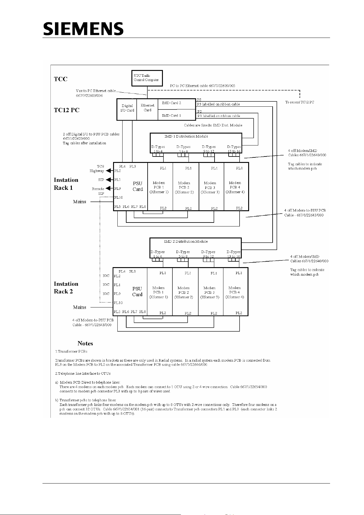
ITU Rack
A full ITU rack contains three types of board; four modem boards, four transformer
boards and a power supply board.
The modem board has four modem chips that communicate with the PC via a V.24
link. These modems are connected to the OTU via the telephone lines in either
radial, multidrop or multipoint format. There is also a pair of test jacks on the
modem board to allow connection to the Instation test set to monitor
communications data and measure signal levels.
The transformer board is used, when the system is in radial configuration, to split
each modem to up to eight telephone lines. This gives a maximum of 128
telephone lines per rack.
The PSU board supplies power to the ITU rack. It also interfaces between the PC
and the SIP and allows connection to a TC8 ITU rack. This facility would be used
should a TC8 system be expanded with TC12.
666/HE/43100/000 Page 6 Issue 9
Page 17

TC12 Installation, Commissioning & Maintenance Handbook
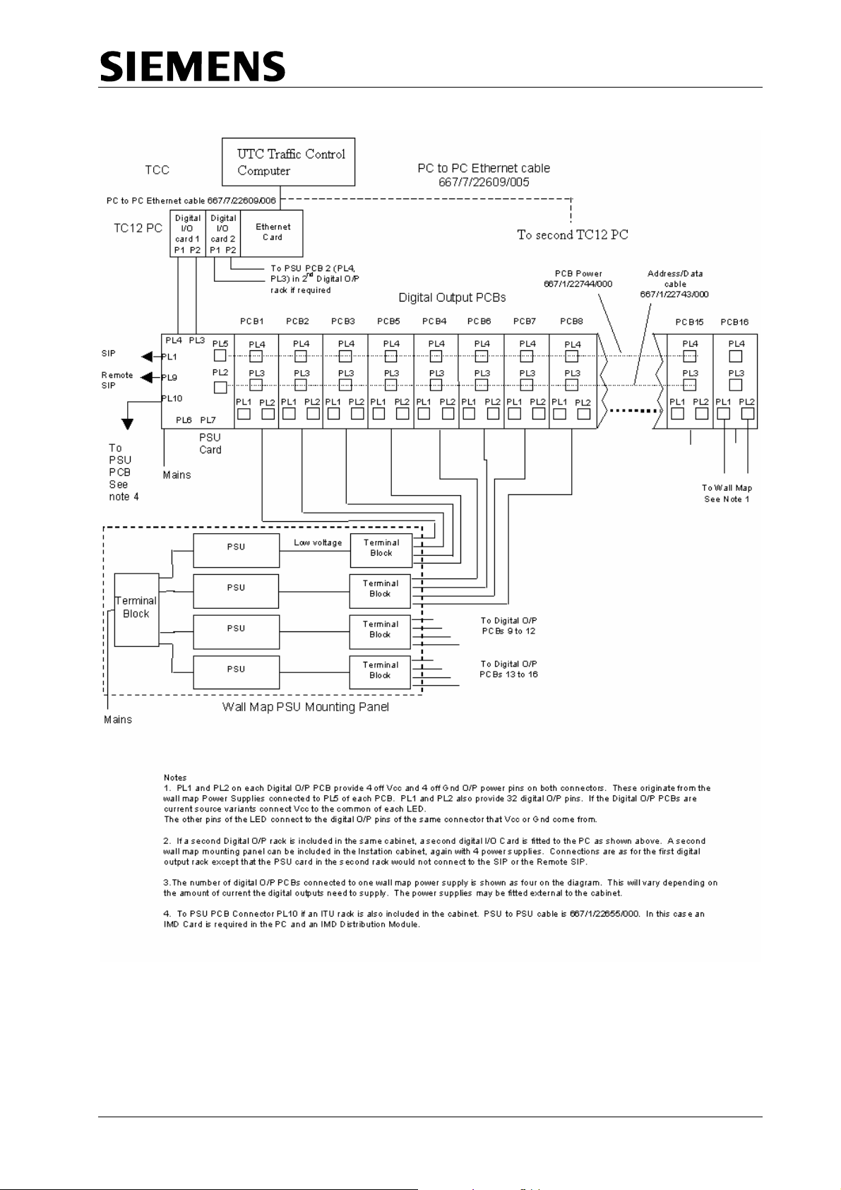
Digital Output Rack
The Digital output rack contains one Instation rack Power Supply Card and
between one and sixteen Digital Output boards, each capable of driving 64 LEDs
at up to 30 V 25 mA. There are two variants of Digital Output board, one sources
current and the other sinks current. The system could be used for any application
requiring digital output, not just wallmap driving.
Instation Test Set
The Instation Test Set (ITS) is housed in an attaché case, and connects to either
the Modem PCBs or the OTU PCBs. It contains a PC, a modified ITU modem
board, an ITS logic board and two power supplies. One power supply is the same
unit as on the PSU board in the ITU rack and is used to power both the boards,
whilst the other is the PC PSU. The ITS provides for connection to the Modem or
OTU board as well as use as a handset.
Outstation Test Set
The Outstation test set is a portable unit housed in a small grey metal case. It
requires a mains supply for operation and two cable forms with which to interface
with the OTU being tested.
Freestanding Outstation
The freestanding outstation is a rack that can be bolted into any Traffic Controller.
It contains a Power Supply, an OTU PCB and up to four detector PCBs. Two
connectors allow the OTU inputs and outputs to be wired up to the controller and
or detector cards, and the OTU is delivered with a cable for this purpose. The
outstation can also provide an LMU facility, and a connector allows current and
voltage monitoring transformers to be attached for this purpose. There is a pair of
test jacks on the board to allow connection to the Instation test set to monitor
communications data and measure signal levels.
Figure 1 and Figure 2 show diagrams of example system connections.
Integral OTU
The integral OTU is a printed circuit card that can be installed in a T400 or ST800
Traffic Controller. It is a version of the T400 Ancillary processor with suitable
firmware to configure it to be an OTU. A single 40-way ribbon cable connector
supplies communication to the controller and all power. A 60 way ribbon cable
connector is fitted for connection to current and voltage monitoring transformers
for use as an LMU. There is no provision for detector inputs - the controller
supplies all detector information.
Connection to the line is via a captive lead terminated in a 6-way BT plug.
There is a pair of test jacks on the board to allow connection to the Instation test
set to monitor communications data and measure signal levels.
666/HE/43100/000 Page 7 Issue 9
Page 18
TC12 Installation, Commissioning & Maintenance Handbook
Figure 1 - System Diagram for Digital Output Rack connection to a Wall Map
666/HE/43100/000 Page 8 Issue 9
Page 19
TC12 Installation, Commissioning & Maintenance Handbook
Figure 2 - System Connection for two ITU Racks
666/HE/43100/000 Page 9 Issue 9
Page 20

TC12 Installation, Commissioning & Maintenance Handbook
2 TC12 INST
2.1 SPECIFICATION
2.1.1 Mains voltage ranges
The Instation will work over: 98 – 132 V RMS
198 – 264 V RMS
Note. The voltage range of the PC used in the Instation should be checked in the
manufacturer's literature and note should be taken of any links/switches
that need setting for different voltage ranges.
2.1.2 Mains frequency range
All TC12 equipment will work from 47 Hz to 63 Hz
2.1.3 Mains current
Instation Cabinet and PC without racks 1.0 A @ 240 V
ITU Rack (Fully equipped) 200 mA @ 240 V
igital Output Rack (Fully equipped) 4.5 A @ 240 V
D
1024 LED
Digital Out Rack (Fu
he figures above are added together for the system used:
T
A
n ITU cabinet with two ITU racks will use:
.0 + 0
An ITU cabinet with two 15mA Digital output racks will take:
+ 2.75 + 2.75 = 6.5 A
.2 + 0.2 = 1.4 A 1
ATION
s at 24 V 25 mA per LED
put lly equipped) 2.75 A @ 240 V
51024 LEDs at 24 V 1 mA pe
r LED
2.1.4 Temperature and humidity requirements
The ITU will work over: 0 °C to 40 °C
Humidity: 20%-80% non-condensing
666/HE/43100/000 Page 10 Issue 9
Page 21
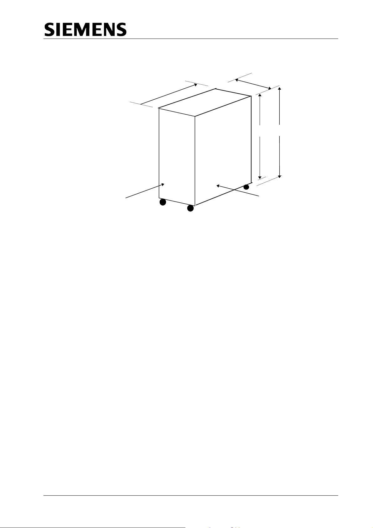
2.1.5 Size and Weight
A
TC12 Installation, Commissioning & Maintenance Handbook
inet - External Dimensions Figure 3 - TC12 Cab
585
875
1625
1540
FRONT
ll dimensions in mm
SIDE
Weight:
Cabinet 111 Kg
ITU Rack 8.4 Kg
igital Output Rack 8.3 Kg
D
Note: The weight of the cabinet does not include any of the PC equipment, and
the weights specified for the racks are with their full complement of PCBs.
666/HE/43100/000 Page 11 Issue 9
Page 22

TC12 Installation, Commissioning & Maintenance Handbook
2.2
INSTALLATION
afety Notes on TC12 Instation
S
Only authorised/trained personnel are allowed to have access behind the
doors/p
a
ccess anything behind these doors/panels.
O
nly an authorised/trained person (trained in the safety aspects of working on
mains powered equipment, is allowed to setup/change any switch positions in the
Instation equipment and/or use any of the free mains sockets within the equipment
and/or connect/use t
If be
the Audible alarm on the system fault indication panel (SIP) sounds it should
cancelled as required from the UTC TCC terminal. If the reason for the alarm is a
UTC TCC failure, an authorised/trained person (trained in the safety aspects of
working with mains powered equipment), should be asked to cancel the audio
alarm, using the au
O
n site safety tests, as described in section 2.3.1, must be carried out before the
Instation is attached to the mains. If after the on site earth continuity test, any rack
or panel is removed or replaced, then the earth continuity check to that item
should be repeated.
anels of the TC12 Instation Cabinet. Users/operators must not attempt to
he TC12 Instation Test Set at the Instation.
dio off switch on the PSU PCB.
2.2.1
Cabinet
T hows the
he TC12 Family Tree part number is 667/DZ/22600/000. This s
structure of part numbers within the TC12 system. The top-level part number for
the TC12 Instation is 667/1/22
The racking space is 32U high, and contains five 6U positions and one 2U
po major
sition, refer to drawing 667/GA/22600/000 which shows the position of the
com
ponents fitted to the cabinet. These include:
Master Switch Panel Assembly fitted to rear of cabinet, height 2U
(667/1/22603/000)
M 2U (667/1/22605/000)
ains Socket Assembly, fitted to front of cabinet, height
System Fault Indication Panel (F
TC12 PC Mounting Chassis (667/2/22621/0
IMD Distribution Mounting Panel (667/2/22636/000)
A
ddi ntio ally 1 or more TC12 19" Instation Racks (height 6U, refer to separate
draw
ing 667/GA/22626/000) will be fitted - these contain PSU PCBs, Modem
PCBs and possibly Transformer PCBs, all of which are described in later sections.
The g
Instation may contain 19" Digital Output Racks (height 6U, refer to drawin
667/GA/22626/001) as well as, or instead of TC12 19" Instation Racks.
Optionally a TC12 Outstation can also be fitted to the Instation cabinet, for test
purposes. The Outstation is 5U high and therefore, if fitted, a 1U blanking panel is
also included (667/1/22613/000)
600/000.
IP), height 6U (667/1/22667/000)
00)
666/HE/43100/000 Page 12 Issue 9
Page 23

TC12 Installation, Commissioning & Maintenance Handbook
U
nused 6U positions are fitted with a 6U blanking panel (561/4/20899/022)
2.2.2 PC
The C s not have a motherboard;
T 12 PC is not like most PCs in that it doe
instead the processor card and the other
There are 2 types of TC12 PC which may be used and are described below:
cards are plugged into a back plane.
2.2.2.1
2.2.2.2 Flat Panel PC
2.2.2
Rack Mount PC
The Rack Mount PC is a convention desktop style of PC which sits on a shelf in
the TC12 cabinet. It has a conventional keyboard attached to it and needs a
sep a checking of its operation.
ar te monitor for software installation and any
The Flat Panel PC may be used in situations where a compact TC12 Instation i
required. The PC is normally mounted in a 19” rack an
screen and membrane keyboard.
.3 TC12 PC Operating System
The TC12 PC software uses DOS as its operating system. The TC12 PC
normally comes with DOS pre-installed. If, however, if DOS is not installed then
the PC manufacturer's set up instructions should be followed.
When initialising the PC, check the working voltage range of the PC is
suitable for th
m
anufacturer's instructions for any switches/links etc., which need to be
changed in order for the PC to work with the intended m
e mains supply that is going to be used. Follow the
s
d has an integrated LCD
SAFETY NOTE!
ains supply.
2.2.2.4
2.2.2.4.1 Rack Mount Data Transmission PC
666/HE/43100/000 Page 13 Issue 9
TC12 PC Configurations
The following combinations of TC12 PC may be used:
A rack mount PC which is to be used for data transmission would normally have
the following, additional, cards installed
• Ethernet Card (Etherlink 3) (not needed if processor card has built-in
Ethernet)
• Digi I/O Card
• Intelligent Modem Driver Card (IMD) either Xi or Xe (1 per ITU rack)
in it.
Page 24

TC12 Installation, Commissioning & Maintenance Handbook
2.2.
2.4.2 Rack Mount Wall Map PC
A rack mount PC which is to be used for driving the LEDs on a wall map would
normally have the fol
• Ethernet Card (E 3) (notherl
Ethernet)
• Digi I/O Card (1 per digital output rack)
2.2.
2.4.3 Flat Panel Data Transmission PC
A flat panel PC which is to be used for data transmission wo
the following, additional, cards installed in it.
• Digi I/O Card
• Intelligent Modem Dri
2.2.2
.5 3Com Etherlink 3 Ethernet Card Set Up
The Ethernet card (part number 667/7/22609/014) needs a half slot in
ll slot can be used if there are no half slots available. fu
The setting up of a 3Com Etherlink 3 card is described below. There are no links
or j rs on a configuration program.
umpe the card and the set up is performed using
Wit Ether ed up and at the C: DOS
h the net card installed in the PC, the PC boot
prompt The TC12 software installation disk should be inserted into the PC’s floppy
driv the f p program:
e and ollowing command used to run the set u
lowing, additional, cards installed in it.
ink t needed if processor card has built-in
uld normally have
ver Card (IMD) Xem.
the PC; a
A:\ELNK3\3C5X9CFG.EXE
The set up part of the program to set the parameters listed below to the values
shown:
P abled
lug and Play Dis
I/O Base Address 0H
Int Lev
errupt Request el 3
Transceiver type Auto Select
Network Driver Optimisation DOS Client
o : If Plug and Play is enabled, this should be disabled first, the configuration
N te
sav nd PC ot efo ny r s gs h
ed a the rebo ed b re a othe ettin are c anged.
2.2.2
.6 UM9008 On-Board Ethernet Set Up
Where the processor card has a built-in Ethernet controller (UM9008) the UM900
configuration and diagnostic utility program should be run before any boards are
lled in the PC. To run the program the TC12 software installation disk should
stain
be inserted into the PC’s floppy drive and the following command used to run the
diagnostic utility program:
A:\UM9008\DIAG9008.EXE
30
8
The first screen of the DIAG9008 program shows the current configuration with the
options of Accept and Exit, Diagnostics, or Configuration. To change th
configuration, select Configuration, followed by Modify Configu
666/HE/43100/000 Page 14 Issue 9
ration. The arrow
e
Page 25
TC12 Installation, Commissioning & Maintenance Handbook
keys are then used to select the items to change; only the Interrupt Request Level
and the Base Address can be changed. The parameters should be set to the
values shown below:
I/O Base Address 300H
Interrupt Request Level 3
N t
ote: If an Etherlink 3 card is to be used in a PC with a built-in Etherne
connection the Etherlink 3 card settings must be those in 2.2.2.5; The UM9008
s e o be
ettings of Int rrupt Request Level and the Base Address must be changed t
d ict
ifferent from those of the Etherlink 3 card, choosing values which do not confl
with those req
uired for the IMD cards and the DIGI I/O card.
2.2.2.7 Digi I/O card and cable
This Digi I/O card (part number 667/7/22609/004, PCDIO48-P needs a half slot
the PC; a full slot can be used if there are no half slots available.
The various blocks of jumpers on the board should be set as follows:
Jumper Setting
JP1 The N/A jumper, only, should be bridged
JP2 No jumpers should be fitted
JP3 All Jumpers should be set to position B
JP4 All Jumpers should be set to position B
JP5 All Jumpers should be set to position B
The address of the board(s) should be set using S1, the Base Address DIP switch,
as follows:
rd e dd
Boa Numb r A ress
1 320H
2 (if re d) 32quire 8H
The corre ding dress itch ttings :
A9 A8 A7 A6
OFF OFF ON ON OFF ON ON ON 320H 1
OFF OFF ON ON OFF ON OFF ON 328H 2
The switch positions are labelled to indicate which switch corresponds to A2
through to A9. A label also indicates what position the switches should be in for
N
O
Two 50-way ribbon cables (part number 667/1/22629/000) are used to connect the
Digi I/O card to the PSU board in the ITU rack:
One cable is attached from the connector labelled J1 or P1 on the DIGI I/O Card to
connector PL4 on the PSU board, (the PSU board has a note on the silk screen
next to PL4 which reads 'CONNECTION TO P1 DIGI I/O (PC)'.
spon ad sw se are
s
A5 A4 A3 A2 Address Board
in
666/HE/43100/000 Page 15 Issue 9
Page 26

TC12 Installation, Commissioning & Maintenance Handbook
The second cable is attached from the connector labelled J2 or P2 on the DIGI I/O
ard to connector PL3 on the PSU board, (the PSU board has a note on the silk
C
screen next to PL3 which reads 'CONNECTION TO P2 DIGI I/O (PC)'.
Note: The two 50-way ribbon cables are to be connected to the card before it is
installed into the PC.
WARNING Please ensure cables are connected correctly, as they are not
polarised. After installation the cables should be labelled to show
which is connected to P1 and which is connected to P2.
2.2.2.8 D ca nd es
IM rds a cabl
T re are er e D a tr u ich e b
he 3 diff ent typ s of IM cards nd dis ibution nit wh hav een
u in T s . T iff es ns n c elo
sed C12 In tations heir d erenc and i tallatio is des ribed b w:
2.2.2.8.1 DIGI PC/16i
The DIGI PC/16i comprises a full length ISA card (DIGI part number 50000160)
and an IMD Distribution Unit (labelled PC/16I I/O MATE INTERFACE). The PC
board has 3 jumpers (J1, J2 and J3) and 2 DIP switches (DS1 and DS2).
The 3 jumpers are used to set the local program memory size, which should be
64K. Each of the 3 jumpers has 3 pins which are numbered from top to bottom.
Each jumper should be set so that pins 2
Set the address of the dual-ported RAM to E0000 using DIP switch 1 (DS1)
positions 1 to 8, as shown belo
Address SW1 SW2 SW3 SW4 SW5 SW6 SW7 SW8
E0000 ON OFF OFF OFF ON ON ON ON
D0000 OFF ON OFF OFF ON ON ON ON
A0000 ON OFF ON OFF ON ON ON O
[ON = PUSH SWITCH DOWN]
If, when the program is run, an address error is reported, the next available
address from the three listed above, should be tried.
, more than one IMD board is installed in a TC12 PC, the address of the dual-
If
ported RAM on each board be set the same.
w:
and 3 are bridged.
N
666/HE/43100/000 Page 16 Issue 9
Page 27

TC12 Installation, Commissioning & Maintenance Handbook
Set the I/O Port addresses of the boards using DIP switch 1 (DS1) positions 9 to
11, as shown below:
Board SW9 SW10 SW11 Address
1 ON OFF OFF 0x100
2 ON ON OFF 0x120
3 OFF OFF ON 0x200
4 ON OFF ON 0x220
Set the interrupts using DIP switch 2 (DS2), positions 1 to 8, as shown below:
Board SW1 SW2 SW3 SW4 SW5 SW6 SW7 SW8 Interrupt
1 OFF OFF ON OFF OFF OFF OFF OFF IRQ5
2 OFF OFF OFF OFF OFF ON OFF OFF IRQ11
3 OFF OFF OFF OFF OFF OFF OFF ON IRQ15
4 OFF OFF OFF ON OFF OFF OFF OFF IR
2.2.
2.8.2 DIGI AccelePort 16e
he DIGI PC/16i comprises a full length ISA card (DIGI part number 60000200)
T
a
nd an IMD Distribution Unit (labelled Digi AccelePort 16e ISA DB25M RS232).
The PC board has a single jumper (J1) and 2 DIP switches (DS1 and DS2).
The jum
The jumper has 3 pins which are numbered from left to right. The jumper should
be set so that pins 2 and 3 are bridged.
The setting of the2 DIP switches, DS1 and DS2, is the same as for the DIGI
PC/16i board (See 2.2.2.8.1).
per is used to set the local program memory size, which should be 64K.
Q7
2.2.
2.8.3 DIGI AccelePort Xem
he DIGI AccelePort Xem comprises a three quarter length Xem ISA Host Adapter
T
(419/4/95931/000 - DIGI part number 77000211), a 16em DB25 Module
(653/4/05229/000 - DIGI part number 76000073
(707/4/08514/000 - DIGI part number 62080060). Each 16em DB25 Module is
supplied with a short cable which enables a maximum of 4 16em DB25 Modules to
be daisy chained together. Two 16em DB25 Modules may be powered from the
ISA Host Adapter. Additional Modules require auxiliary power supplies
(605/4/08678/000 - DIGI part number 76000321).
he C alled. The
T P must be powered off before the Xem host adapter card is inst
PC should remain off until the 16em DB25 Modules have been connected to the
host adapter. The only set up required on the Xem host adapter is to set the I/O
por d
t a dress to 124H-127H using DIP switch DS1
Addr
ess SW1 SW2 SW3 SW4
124H-127H OFF ON ON ON
) and a Xem 5ft Cable
666/HE/43100/000 Page 17 Issue 9
Page 28

TC12 Installation, Commissioning & Maintenance Handbook
2.2.2.9 IMD Distribution Modules (16i and 16e Units)
The IMD distribution Units (part number 667/7/226
IGI 16i and DIGI AccelePort 16e units are secured by clamps (667/2/22638/000)
D
to the IMD Distribution Mountin 636/000, see TC12 cabinet
assembly drawing 667/GA/22600/000 and TC12 IMD/Modem Panel asse
drawing 667/GA/22635/000). This mounting panel is a hinged aluminium panel a
the back of the Instation. Each IMD Distribution Unit has two ribbon
P2 and P3. The other end of these ribbon cables connects to the two connectors,
labelled P2
One IMD module contains 16 25-way D-type connectors. A group of four DConnectors connect via a single 24-way cable to one modem PCB, see section
2.2.4.2 s on one
modem PCB.
The IMD Cables should be secured to the bottom of the hinged IMD panel.
Note: If it becomes necessary to replace either the IMD distribution box or the IMD
PCB they should both be changed at the same time.
Note: Before fitting the card into the PC, the card and the distribution unit should
and P3, on the IMD card in the PC.
. This cable provides V.24 signals from the PC to the four modem
be laid out on the bench and positions of the folds in the two ribbon
cables, determined. Where the ribbon cables pass through the rear of the
PC they should be strapped together with insulating tape. The card has to
be fitted to the PC before the ribbon cables are finally plugged into the
card.
g Panel (667/2/22
09/010), which are part of the
cables labelled
mbly
t
2.2.2.10 IMD Distribution Modules (Xem Units)
T
he 16em DB25 Module is the wrong shape to be mounted on the hinged
alumin
suitable shelf is a 1U Modem shelf (RS Part No 228-9441).
2.2.2.11 T
The TC
TC12 required to
u e
T
versio
If the T
attach
ium panel and is normally mounted on a shelf within the TC12 cabinet. A
C12 Instation PC Software Installation
12 PC Software is supplied on a single floppy disk. There are 2 versions of
software currently in use, Version 7.4 should be used if it is
pdat an existing installation; Version 8.3 should be used on all new installations.
he installation procedure for both software versions is basically the same, but
n 8.3 has the following additional features:
•
Allows a PC processor card with onboard Ethernet to be used
•
An option to disable the playing of the start up tune
•
An option to disable the driving of the SIP.
• The default screen display shows the state of the TCC Ethernet
and the System and Operational alarm states.
C12 PC does not have a built-in monitor, a VGA monitor should be
ed before starting the software installation process.
connection,
666/HE/43100/000 Page 18 Issue 9
Page 29
TC12 Installation, Commissioning & Maintenance Handbook
N
The so
ftware installation procedure is as follows:
SAFETY NOTE
The P
distrib
safety age.
C should be plugged directly into the mains, and not via the mains
ution panel on the Instation, since the Instation has not undergone on-site
tests, described in the commissioning section, at this st
Figure 4 - TC12 Instation PC Installation Screen (7.4)
TC 12 INSTATION PC INSTALLATION
EtheNrnet Card
EtherLink II (3c 5 03)
DEPCA
DEC Eth
DEC Etherworks Turbo
Digital I/O boards
Board #1
Board #2
erworks LC
OK
Not Installed
Use the cursor keys → or ← to move between menus
Use Enter or Return ↵ to select
umber of boards
1
IMD-DS1, SW1-8 Settings
Use address 0 x E0000
1 2 3 4 5 6 7 8 . . .
Use the cursor keys ↑ or ↓ to move betwe en sel e ct i ons on m e nu
Press Esc to exit
Start Installation
o
Yes
Quit Installation
IMD boards
Board #1 OK
Board #2 Not Installed
Board #2 Not Installed
Board #2 Not Installed
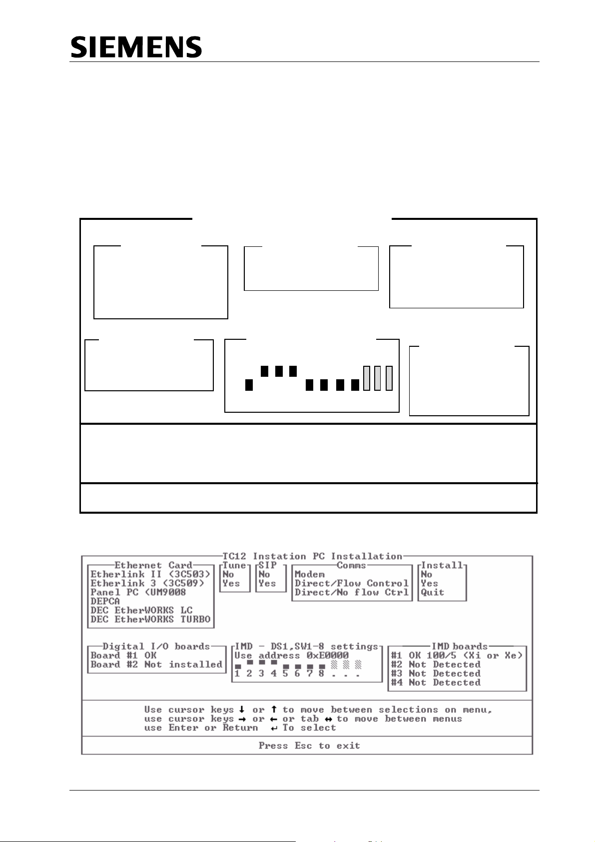
Figure 5 - TC12 Instation PC Installa
tion Screen (8.3 & later)
666/HE/43100/000 Page 19 Issue 9
Page 30

TC12 Installation, Commissioning & Maintenance Handbook
(1) Before starting th
should be configur
appropriate.
(2) Insert ftware disk into the PC and then switch the PC On. The
Installation softwar
short time followed
should look somet
(3) Check tus for each IMD board is correctly indicated (see below
for possible display messages and actions).
If the Installation scree
key presses check the
card (see section 2.2.2.8). If the switches are set correctly chang
next available address as indicated in 2.2.2.8.1 and restart the installation.
(4) Follow the instructions displayed for moving around the screen.
(5) Select the type of Ethernet card that was installed
options on the 'Ethernet card' menu. (If an on-bard Ethernet connection is
being used, select the ‘Panel PC (UM9008)’ option.) On Version 7.4
s
n
the TC12 So
ftware is Version
that the sta
oftware, move across to the 'Number of boards' menu and enter the
umber of Ethernet cards that are installed in the PC - normally 1.
e TC12 software installation the Ethernet connection
ed using the instructions given in 2.2.2.5 or 2.2.2.6, as
e will auto-boot and 'SIEMENS' will be displayed for a
by the TC12 Instation PC Installation Screen, which
hing like Figure 4 if the software is Version 7.4. If the
mething like Figure 5. so 8.3 it should so
n has locked up altogether and does not respond to
Ram address switches are set up correctly on each
e to the
in the PC from the
O
(6) n version 8.3 Software, move to the ‘Tune’ menu and select YES or NO,
d
epending upon whether or not you wish the tune to be played when the
T
C12 PC boots up. Move across to the 'SIP' menu and select YES if a SIP
is
installed in the TC12 cabinet, otherwise select NO.
) On Version 8.3 Software, move to the ‘Comms’ menu and select one of the
(7
following options:
Modem If a conventi
the Instation to the OTUs.
Direct/Flow Control
Direct/No Flow Cntrl If direct Instation to outstation, RS232,
(8) Check the status of the DIGI I/O cards shown in the Digital I/O box.
Correctly installed cards will show as ‘OK’, cards which are not installed will
show as ‘Not installed’ and cards which are incorrectly installed will show an
error message which may give a clue as to the nature of the problem.
(9) Check th
installed cards will be shown as ‘OK’ together with 2 numbers separated by
a ‘/’. The first number is the address of the board and the second number
the IRQ numbe
which has been detected, either ‘Xi or Xe’ or ‘Xem’. Any boards which have
not been detected by the software will be shown as ‘Not detected’.
e status of the IMD cards shown in the IMD Cards box. Correctly
r of the board. Also shown will be the type of IMD board
If direct Instation to outstation, RS232,
communications are being used with CTS/RTS
flow control.
communications are being used without
CTS/RTS flow con
onal leased line is being used to connect
trol.
666/HE/43100/000 Page 20 Issue 9
Page 31

TC12 Installation, Commissioning & Maintenance Handbook
(10) If the indications for the DIGI I/O and IMD cards are as expected, move
across to the nd hit return. The TC12
Software wil e PC. Should the DIGI
I/O cards and/or IMD cards not be shown as expected then choose the
‘Quit’ option and correct the problem.
(11) Exit the Installation software. Eject the TC12 Software disk and keep this as
a backup.
(12) Disconnect the PC from the mains and disconnect the monitor. The PC can
now be installed in the TC1
2.2.
2.11.1 Error Messages during TC12 Instation PC Software Installation
Messages and Errors that may be displayed on the 'Digital I/O boards' and 'IMD
boards' status menus during the software installation and suggested corrective
actions are shown below:
Displayed Message Action to be taken
OK None - Card installed OK
Not Installed None unless card should be present; check card is insert
Ram Error IMD cards only - c
Switches set correctly - change to next available address
Switches set incorrectly - correct and restart installation.
Faulty Replace card.
Int. Failed Check Interrupts set up correctly on the card (see2.2.2.8
'Install' menu, select the 'Yes' option a
l now be installed on the Hard disk of th
2 cabinet.
correctly in PC slot, check switch settings of Port address
for IMD cards or address for
2.2.2.7 or 2.2.2.8).
heck Ram address switches set up
correctly on card (se
as indicated in 2.2.2.8and restart installation.
e section 2.2.2.8).
Digi I/O cards (see section
ed
).
2.2.2
.12 PC Mounting Chassis
he PC is accessible from the back of the Instation. It is placed on the PC
T
ounting chassis (6 of the Instation.
m 67/2/22621/000), which is a shelf at the top
The PC is not visible from the front of the Instation as the System Fault Ind
Panel is fitted across the fron ocket on tt. The PC mains lead plugs into a s
Master switch Panel assemb
Note: Lengths of 'U' channel (e.g. 915/4/03641/000) should be cut and placed
along the edges of the cut-outs in the back of the PC through which cables
pass, in order to eliminat
edges.
there isIf ore than one IM
avoid the possibility of the
jacent PC possible the IMD PCBs should be located
such that a spare slot exists betwe
666/HE/43100/000 Page 21 Issue 9
m D card in the PC, care should be taken to
ly at the back of the Instation.
e the possibility of the cables chafing against the
IMD cables chafing on the solder side of
isad Bs. As far as
en the IMD cables and adjacent PCBs.
ication
he
Page 32

TC12 Installation, Commissioning & Maintenance Handbook
N
N
N
N
2.2.3
Systems Fault Indication Panel (SIP)
The SIP (part number 667/1/22667/000) is 6U high and is screwed to the Instatio
racking in front of the PC.
the Audible alarm on the system fault indication panel (SIP) sounds it should be
If
cancelled as required from the UTC TCC terminal. If the reason for the alarm is a
UTC TCC failure, an authorised/trained person (trained in the safety aspects of
working
larm, using the audio off switch on the PSU PCB.
a
with mains powered equipment), should be asked to cancel the audio
Under System Failure conditions the output relays for a remote SIP switch on and
off, which gives rise to a clicking sound. If the customer wishes to stop this sound
and there is n
e PSU board: R25, R41, R44, and R47. See 666/CF/02249/102 at the back of
th
o remote SIP fitted the following Resistor links may be removed from
the Handbook.
n
2.2.4
19" Racking PCBs
Figure 6 shows a front view of a fully equipped rack
r the rack, part number 667/GA cards should only be put in the
fo /22626/000). The
um of four racks mslots in the order shown. A maxim ay be fitted to an Instation.
Figure 6 - ITU 19" Rack (Front View)
6U Rack, Radial System
T
R
A
S
2
PSU
M
O
D
E
M
1
T
R
A
S
1
M
O
D
E
M
2
M
O
D
E
M
3
(there is an assembly drawing
T
R
A
S
3
M
O
D
E
M
4
T
R
A
S
4
1.5”
666/HE/43100/000 Page 22 Issue 9
Page 33

TC12 Installation, Commissioning & Maintenance Handbook
2.2.4
.1 PSU PCB (inc. Digi I/O, SIP (local and remote), Watchdog and TC8 cables)
See Figure 7 for a diagram of the board layout showing the position of connectors
LEDs, switches, volume control.
SAFETY NOTE
When installing the PSU PCB in the TC12 Instation cabinet the earth strap should
be bolted on to the PCB
hen the PSU PCB is being removed, disconnect the mains plug from the mains
w
socket on the PCB, bef r earth straps are situated
on the right-hand 19" upright of the Inst
available at the correct height for up to four racks of TC12 that may be installed.
The earth strap comes with a bolt (+ star washer) and tag on one end which is
attached to the hole situated below the power supply on the PCB (see Figure 7 for
position of ground hole).
The switches on the PSU PCB should be set as follows:
(See Figure 8 for diagrams of switch settings)
This should be set to '1'. If a second rack is fitted in the Instation then the position
of the switch, on the PSU Board in the second rack, does not matter. If there is
more than one PC connected to the same Ethernet link, the switch should be set
to 2 for the PSU Board connected to the second PC, 3 for the PSU Board
associated with the third PC, etc. The switch setting should correspond to the last
digit of the TC12 PC SCN in the associated UTC System’s database.
This is a 4-way DIL switch. The usual setting for this switch is as follows:
The function of this switch is to enable certain inputs to the board, to cause the low
frequency alarm tone to sound.
Switch position Input signal
1
2 Audio 2 Signal
3
4 Failure of UTC TCC
Closing the appropriate switch causes the input signal indicated to cause a low
frequency alarm tone, should the signal become active. Note if more than one
switch is closed, any of the associated input signals becoming active, will cause
e alarm to sound. th
The high frequency alarm tone is sounded if the Audio 2 Signal becomes active.
This is not configurable. It can only be disabled using the audio on/off switch (see
below).
before the mains cable is plugged into the PCB. Similarly
ore removing the earth strap. Fou
ation cabinet, i.e. there is one strap
S1 - PC Address
S2 - Audio Alarm Configuration Switch
switch position 1 should be closed
switches 2, 3 and 4 should be open.
Audio 1 Signal
Failure of PC
,
666/HE/43100/000 Page 23 Issue 9
Page 34

TC12 Installation, Commissioning & Maintenance Handbook
S3 - Audio ON/OFF
This switch should normally be set to on. If it is set off then LED LP2 will light once
the board is powered up and the local SIP audio alarm will not sound in the event
of any faults.
If the Audible alarm on the system fault indication panel (SIP) sounds it should be
cancelled as required from the UTC TCC terminal. If the reason for the alarm is a
UTC TCC failure, an authorised/trained person (trained in the safety aspects of
working with mains powered equipment), should be asked to cancel the audio
alarm, using the audio off switch on the PSU PCB.
Volume Control
The volume of the audio alarm is adjusted by turning the screw on potentiometer
RV1.
Connector PL1
C
onnect the cable (part number 667/1/22612/000) from the local SIP into
connector PL1 on the PSU PCB in the first rack. The PCB will need to be in the
c Instation
ard guide for the cable to reach. If there are additional 19" racks in the
there is no connection ards in these racks.
Co
nnector PL2 - No connection normally. This is used to connect to digital output
boards when used in a digital output rack (See section 2.2.5.2), as well as for
interfacing with the Telecommand 8 highway.
Connectors PL3 and PL4 connect to the Dig
2.2.2.7.
Connectors PL5 to PL8 connec
onnector PL9 - No connection normally (used for a remote SIP only).
C
Connector PL10 - Additional Racks In the Same Cabinet
If
a further rack are included in the Instation then the PSU board on the second
rack is s
Connect from PL10 on the first PSU PCB to PL10 on the second PSU PCB, using
able 667/1/22655/000. If a third rack is fitted, connect from PL10 on the second
c
PSU PCB to PL10 on the third PSU PCB and so on.
Connecto
Connecto ks, connect to modem
boards in those racks.
et up as follows
rs PL1, 2, 3, 4 and 9 are not used on the PSU PCBs of additional racks.
rs PL5 to PL8, on the PSU PCBs of additional rac
to connector PL1 on the other PSU bo
Connector PL2
Connectors PL
Connectors PL5 to PL8
t to Modem PCBs as described in section 2.2.4.2.
Connector PL9
3 and PL4
i I/O card as described in section
666/HE/43100/000 Page 24 Issue 9
Page 35

TC12 Installation, Commissioning & Maintenance Handbook
Figure 7 - PSU Board Layout
LP1
S1
S3
LP2
Varia
Hole fo ttaching
earth st
TC12 c
GND
S2
TP4 TP5 TP6 TP7 TP8 TP9
+12V +5V +5V GND AGND -12V
nt
Power Supply
r a
rap from
abinet
1
PL10
1
10
PL9
PL1
26
20
11
1
1
1 (TOP)
PL5
14
1 (TOP)
PL6
50
50
50
14
PL2
PL3
PL4
1 (TOP)
PL7
14
1 (TOP)
PL8
14
MAINS
SOCKET
Ser. No.
Mains Wires
666/HE/43100/000 Page 25 Issue 9
Page 36

TC12 Installation, Commissioning & Maintenance Handbook
Figure 8 - PSU Board Switch Settings
666/HE/43100/000 Page 26 Issue 9
Page 37

TC12 Installation, Commissioning & Maintenance Handbook
Setting the Voltage Range of the PSU
The Power supply fitted to every PSU board used in the system (part number
667/7/22631/000, manufactured by Daren Electronics PLC type PP40-30). An
internal link in this power supply needs to be set for the nominal mains voltage.
See Figure 9 for link setting; set to 110 V position for 98 V to 132 V mains voltage
range, set to 240 V for 198 V to 264 V mains voltage range.
Figure 9 - PSU Board Mains Voltage Range Setting
PSU
240V
110V
Low Voltage
Connections
Co Ma
nne s
ins
ction
1 CB is plu d in the ins ppl
. Make sure that the PSU P not gge to Ma Su y.
2. Disconnect the low voltage and Mains connectors from the PSU.
3. Remove the four screws that attach the PSU to the PCB.
4. Rem m the PSU rem ing urth fou rew
5. Set the Mains voltage link inside PS to th equ d p ion
6. Re screw the U k o th CB.
ove the cover fro by
theovU
110 V o
r 240 V, as shown in Figure 9.
a f
e r
er
ire
place the cover and PS bac n to e P
r sc
osit
s.
:
Ensure that the PCB is fi
tted the correct way around i.e. the Mains
connector and low voltage connector are at the correct ends of the PCB.
7. Re-connect the two PSU
connectors
2.2.4.2 Modem
Figure 9 shows the position of the swit odem PCB.
PCB and Modem power cable
es and connectors on the Mch
Ensure that the correct variant has been supplied e.g.
666/1/02243/000 for the UK.
666/1/02243/000 or 666/1/02243/001 for non-UK (the /001 variant includes extra
components; metal oxide varistors and gas discharge tubes, for surge protection).
The switches on the Modem PCB should be set as follows:
Note: The tables referred to below contain 0's to indicate open switches and 1's
to indicate closed switches. For all the switches push the switch down to
the left for a 0 and down to the right for a 1. The 0 and 1 position is shown
on the silkscreen underneath switch SW7.
666/HE/43100/000 Page 27 Issue 9
Page 38

TC12 Installation, Commissioning & Maintenance Handbook
1. SW1 - Mode Select switch
nsure that the Mode Select ee Table 1 for
E
ettings. One of the modes s ay DIL switch.
s
Note NO other settings are to be used in the UK.
2. SW2,
3. SW4 Sel r s h (S ).
4. SW5 - T e
The PCB is fitted with a cover (part numb 667/2 2642 0 to 001 r). T
cov AYS be fitted before any connectors are attached to the PCB and
er must ALW
should NEVER be removed whilst any cables are connected to the PCB.
Each Modem PCB has a 14-way ribbon cable (part numbe
a 24-way cable (part number 667/1/22640/000):
The 14-way cable connects the middle header (PL2) on the Modem PCB to the
appropriate 14-way header on the PSU PCB, as follows:
SW3, SW6 and SW7 - Line Level switches
Ensur
setti 2 s s s h s
levels. Each modem PCB contains four DIL switches. SW2 and SW3 are
8-wa
resp
line
Outp nd p ion nd t th ece hr ld. ition
7 and 8 on SW2 and SW3 ar
8-wa es ore mn nd r th ay itch
For U
threshold is set to -39dBm.
Note:
Ensure that the 2/4 Wire
settings).
Table
a tran ar e s is
modems not connected to transformer boards, on board transformers are
select
e that the Line Level switches are set correctly see Table 2 for
ngs). Table how witc ettings corresponding to the different
y DIL switc , us for s ng the line levels for modem 1 and 2
ectively. SW nd 7 ar -way L switches used for setting the
levels for modem 3 and 4.Positions 1 to 4 of all four switches set the
ut Power a osit s 5 a 6 se e R ive T esho Pos
y DIL switch , ign colu s 7 a 8 fo e 6-w sw es.
K use the tput er lways set to -13dBm and the receive
NO other setting except for -13dBm is to be used in the UK.
- 2/4 Wire ecto witc W4
ransform r Sele t switch.
at the ransfo er S ect switch (SW5) is set correctly (see
r settings). In a radial system (i.e. for any modem connecting to
4 fo
sformer bo d, th witch set to off board transformers. For all
ed.
Modem PCB 1 -> PL8 on the PSU PCB
Modem PCB 2 -> PL7 on the PSU PCB
Modem PCB 3 -> PL6 on the PSU PCB
Modem PCB 4 -> PL5 on the PSU PCB
hes
6 a
ou pow is a
T
ed
SW
rmEnsure th
Connector PL
switch is set correctly; s
hown is selected on a 7-w
etti
e 6 DI
e unused. Table 2 shows the setting for the
Selector switch is set correctly (see Table 3 for
c
el
er /2 /00 p, / rea his
r 667/1/22643/000) and
2
666/HE/43100/000 Page 28 Issue 9
Page 39

TC12 Installation, Commissioning & Maintenance Handbook
Connector PL1
The 24-way cable connects the top header (PL1) on the Modem PCB to four 25way 'D' con ion pane
Note: Once installed the 24-way cables should be tagged with a number 1-4
The IMD distribution modules are positioned on the hinged panel with D-type
connectors 1, 5, 9 and 13 along the top row and D-types 4, 8, 12 and 16 along the
bottom row (the numbers are printed alongside the D-types on the IMD distribution
module). The ribbon cables from the IMD distribution modules therefore point back
towards the hinged side of the plate. The 24-way cable with four D-types (from a
modem PCB connections detailed above) can be cable tied along the bottom of
the hinged panel, with the D-type with the shortest wires (i.e. the D-type closest to
the berg connector at the other end) connected to the bottom D-type on the IMD
distribution panel, and the D-type with the longest wires connected to the D-type at
the top of the IMD distribution panel.
onnector PL3 is used to connect to transformer boards in a system where
C
ansformer boards are used (see section 2.2.4.3).
tr
Connector PL3 connects via a special cable to directly to the MDF in a system
where
nectors on the IMD distribut l, as follows:
Modem PCB 1 -> 'D' co
Modem PCB 2 -> 'D' co
Modem PCB 3 -> 'D' co rs 9-12 on the distribution pa
Modem PCB 4 -> 'D' co rs 13-16 on the distribution p
corresponding to the modem PCB number for future identification.
Connector PL3
transformer boards are not used (see Figure 14).
nnecto el
nnecto el
nnecto nel
nnecto anel
rs 1-4 on the distribution pan
rs 5-8 on the distribution pan
666/HE/43100/000 Page 29 Issue 9
Page 40

TC12 Installation, Commissioning & Maintenance Handbook
Figure 10 - Modem PCB Layout
S2
S3
4 Wire
Level
Off PCB ‘0 ’
Level
S6
S7
S1
0 1
Line
Level
Line
Level
S4
S5
Line
Level
Line
Level
Mode
Select
2/4 Wire
Selector
Level
Transformer
Select
2 Wire
Level
On PCB ‘1’
Level
Variant
PL1
24 Way to
IMD panel
PL2
14 Way to
PSU card
PL3
ay ‘D’
37 W
to MDF or
Transformer
PCB.
1 (TOP)
24
1 (TOP)
14
37
1 (TOP)
0 1
For switches SW1, SW2, SW3, SW3, SW5, SW6 and SW7 the switch
is:
OPEN i.e. ‘0’ WHEN
CLO
SED i.e. ‘1’ WHEN PUSHED DOWN TO THE RIGHT
As a
reminder the ‘0’ and ‘1’ positions are shown on the silkscreen below SW1 and
SW7
.
PUSHED DOWN TO THE LEFT, and
For SW4, 4-wire is selected with the switch to the left and 2-wire is selected with the
switch to the right as shown above.
666/HE/43100/000 Page 30 Issue 9
Page 41

TC12 Installation, Commissioning & Maintenance Handbook
Table W1)
1 - Modem PCB Mode Select Switch (S
MODE 1 2 3 4 5 6 7
(Eng use only)
CCITT V.23 M2
1200 BPS HALF DUPLEX
CCITT V.23 M2
1200 BPS HALF DUPLEX
WITH EQUALIZER
CCITT V.23 M1
600 BPS HALF DUPLEX
CCITT V.23 M2
1200 BPS FULL DUPLEX
SWITCH NUMBER
!MC0 !MC1 !MC2 !MC3 !MC4
0 1 0 0 1 1 0
0 0 0 0 1 1 0
0 1 1 1 0 1 0
0 1 0 0 1 0 0
CCITT V.23 M2
1200 BPS FULL DUPLEX
WITH EQUALIZER
CCITT V.23 M1
600 BPS FULL DUPLEX
CCITT V.21 ORIG
300 BPS HALF/FULL DU
See Figure 8 for Switch Positions for Switches 0 and 1
0 0 0 0 1 0 0
0
1 1 1 0 0 0
0 1 1 0 1 1 0
PLEX
0 = SWITCH OPEN
1 = SWITCH CLOSED
666/HE/43100/000 Page 31 Issue 9
Page 42

TC12 Installation, Commissioning & Maintenance Handbook
Table 2 - M , 6 and 7)
odem PCB Line Level Switches (SW2, 3
SWITCH NUMBER
OUTPUT 1 2 3 4 5 6 7 8
POWER
0dBm
-3dBm
-6dBm
-9dBm
-10dBm
-13dBm
1 0 0 0 - - 1 1
1 0 0 1 - - 1 1
0 1 0 0 - - 1 1
0 1 0 1 - - 1 1
0 0 1 0 - - 1 1
0 0 0 0 - - 1 1
-16dBm
RECEIVE
THRESHOLD
-42dBm
-39dBm
-33dBm
0 0 0 1 - - 1 1
- - - - 0 0 1 1
- - - - 0 1 1 1
- - - - 1 0 1 1
SETTING FOR UK
↑ ↑
Switch positions 7 and 8
apply to SW2 and SW3 only.
SW6 and SW7 are 6-way switches
.
0 = SWITCH OPEN
1 = SWITCH CLOSED
See Figure 8 for Switch Positions for Switches 0 and 1
666/HE/43100/000 Page 32 Issue 9
Page 43

TC12 Installation, Commissioning & Maintenance Handbook
Table 3 Mod PCB 2/4 re Se - em Wi lect Switch (SW4)
MODEM 1
MODEM 2
MODEM 3
MODEM 4
Switch 1 → 2 - Wire Switch 1
Switch 2 → 2 - Wire Switch 2
Switch 3 → 2 - Wire Switch 3
4 - WIRE
→Switch 4 2 - Wire Switch 4
1
2
2 - WIRE
3
4
SW4
Operation 2 - Wire Operation 4 - Wire
→ 4 - Wire
→ 4 - Wire
→ 4 - Wire
→ 4 - Wire
Table 4 - Modem PCB Transformer Select Switc
S e number)
witch numbers (Corresponds to Modem with sam
1 2 3 4 5 6
S
et switch to 1 (Closed) to select on board
tra
nsformer for the Modem in question i.e. for
an
y Modem NOT connected to a transformer
board.
S
et switch to 0 (Open) to select off board
tran
sformers for the Modem in question i.e. for
any Modem connected to a transformer board.
See Figure 8 for Switch Positions for Switches 0 and 1
h (SW5)
NOT USED
666/HE/43100/000 Page 33 Issue 9
Page 44

TC12 Installation, Commissioning & Maintenance Handbook
2.2.4
.3 Transformer PCB and Modem/Transformer Cable
Figure 10 shows the layout of the Transformer PCB.
Ensure that the correct variant has been supplied e.g.
666/1/02245/000 for the UK.
666/1/02245/000 or 666/1/02245/002 for non-UK.
he PCB is fitted with a cover (part number 667/2/22647/000 top, /001 rear). This
T
cover must ALWAYS be fitted before any connectors are attached to the PCB, and
should NEVER be
Each Transformer PCB has a ribbon cable (part number 667/1/22646/000) with
14-way connector at one end and a 37-way 'D' connector at the other. This
connects the Transformer PCB (T1, T2 etc.) to its associated Modem PCB (i.e.
M1, M2 etc.).
The cable connects from PL2 on a transformer PCB
odem PCB.
m
Figure 11 shows a
cables are indicated.
These connectors are used for connection to the MDF (see Figure 15).
Ensure that for any unused telephone lines the corresponding switches on the
front of the PCB are set to ON. For example, if the 7th and 8th radial lines of
modem 2 are not used then switches 7 and 8 of S2 should be put to the on
position.
removed whilst any cables are connected to the PCB.
Transformer Board Connector PL2
to PL3 on its associated
rear view of a fully equipped rack. The positions of the ribbon
Transformer Board Connectors PL1 and PL3
ransformer Board Switches S1, S2, S3 and S4
T
a
666/HE/43100/000 Page 34 Issue 9
Page 45

S
S2
S3
TC12 Installation, Commissioning & Maintenance Handbook
Figure 11 - Transformer PCB Layout
37
1
Variant
PL1
37 Way ‘D’
to MDF.
PL2
14 Way to
Modem PCB
PL3
37 Way ‘D’
to MDF.
1 (TOP)
1 (TOP)
14
37
S4
1 (TOP)
Figure 12 - ITU 19" Rack (Rear View)
ITU Rack 6U ,
24 Way connector
to PC
System
PSU
Telephone lin
37 way ‘D’
e I/F
.
IDC connectors
with IDC cable:
14way to 37 Way
PSU
Modem Output
14 Way connector
to PSU
666/HE/43100/000 Page 35 Issue 9
Page 46

TC12 Installation, Commissioning & Maintenance Handbook
2.2.5 Digital Output Rack, PCBs and PSUs
The digital outp at 17 card guides
ut rack is the same size as the ITU rack except th
are fitted. These take one PSU PCB and between 1 and 16 Digital Output PCBs.
The assembly drawing for the rack is 667/GA/22626/001. One or two racks may
be fitted to an Instation.
2.2.5.1 PSU PCB
The PSU PCB is identical to the ITU rack PSU PCB so see section 2.2.4.1 for
configuration details. Details of how to connect to the digital output rack are in the
next section.
2.2.5.2 Digital Output PCB
There are several variants of the PCB, /000 to /099 have current source outputs
and /100 to /199 have current sink outputs. The variants in those two groups are to
cope with different output current limit values.
See Figure 13 for a diagram of the board layout showing the position of
connectors, LEDs switches
and .
Variant No.
S1
LP1 POWER LED
LP1 WATCHDOG LE
14
PL4
1 (TOP)
50
PL3
re 13 - D l Output PCB La out
Figu igita y
D
FS1FS2 FS3FS4
PL1
PL2
PL5
1 (TOP)
40
1 (TOP
40
1 (TOP
)
)
1 (TOP)
Serial Number
14
666/HE/43100/000 Page 36 Issue 9
Page 47

TC12 Installation, Commissioning & Maintenance Handbook
Switch S1 PCB Address
the PSU PCB to 0, the next card to 1 and so Set the switch on the card closest to
on up to F if 16 boards are fitted.
Connectors PL1 and PL2
These connectors are used to take the digital outputs out of the cabinet. Either a
ribbon cable kit (667/1/22742/000) or a discrete wire cable kit (667/1/22742/001)
are used to make up the cables on installation. The pin outs are as follows:
666/HE/43100/000 Page 37 Issue 9
Page 48

TC12 Installation, Commissioning & Maintenance Handbook
Pin PL1 PL2
1
2
3 Output 2 Output 34
4
5
6 Ou 37
7 Out Output 38
8 Out Output 39
9 Out Output 40
10 Out Output 41
11 Out Output 42
12 Out Output 43
13 Out Output 44
14 Out Output 45
15 Out Output 46
16 Out Output 47
17 Out Output 48
18 Out Output 49
19 Out Output 50
20 Out Output 51
21 Out Output 52
22 Out Output 53
23 Out Output 54
24 Outp Output 55
25 Outpu Output 56
26 Outpu Output 57
27 Out 58
28 Out 59
29 Out 60
30 Out 61
31 Out 62
32 Out 63
33 XVC VCC
34 XVC VCC
35 XVC VCC
36 XVC VCC
37 XG GND
38 XG GND
39 XG GND
40 XG GND
Connect pins 1 to 32 to the LEDs on the wall map, and the common pin for those
32 LEDs to XVCC current sink or XGND for current source.
Connect cable 667/1/22743/000, a 50 way cable with 17 sockets, to PL2 of the
PSU PCB and to PL3 of all the Digital Output PCBs in the rack.
Output 0 Output 32
Output 1 Output 33
Output 3 Output 35
Ou utput 36 tput 4 O
tpu Output t 5
put 6
put 7
p ut 8
put 11
put 12
put 13
put 14
put 15
put 16
put 17
put 18
put 19
put 20
put 21
put 22
t 24
t 25
put 26 Output
put 27 Output
put 30 Output
put 31 Output
C X
C X
C X
C X
ND X
ND X
ND X
ND X
put 9
put 10
u t 23
put 28
put 29 Output
Connector PL3
Output
666/HE/43100/000 Page 38 Issue 9
Page 49

TC12 Installation, Commissioning & Maintenance Handbook
Connector PL4
Connect cable 667/1/227
PSU PCB and to PL4 of all the Digital Output PCBs in the rack.
Connect cable 667/1/22717/000
on the wall map PSU mounting panel
outputs of the power supply.
2.2.5
.3 Wall Map PSU
Two Wall Map PSU mounting panels (667/1/22740/000 and /001) can be fitted to
the sides of the cabinet, giving a max
upply 6 A at 24 V. There is a terminal block on each panel to connect the mains
s
to all the PSUs. Each Wall Map PSU (667/1/22741/000) contains another terminal
block and wires to enable wi
of a number of Digital Output PCBs. The actual number of digital output PCBs
depend on the amount of current each PCB is supplying to its outputs. See
667/CA/22741/000 and Figure 2 for wiring details.
44/000, a 14 way cable with 17 sockets, to PL5 of the
Connector PL5
to PL5. The other end wires into a terminal block
, the other side of which connects to the DC
imum of eight power supplies. Each can
ring of low voltage power (for driving outputs) to PL5
will
2.2.6
PSTN Modem
a PSTN modem (667/1/22662/000) is required this may be fitted to the back of
If
the hinged IMD distribution panel at the back of the Instation.
2.2.7
External Cables
2.2.7
.1 Mains Cable
he mains cable to the Instation should be at least 15 Amp cable, and the plug
T
should be fitted with a fuse appropriate to the cable rating. The mains cable is
wired to the input of the master switch p
667/GA/22603/000 for connect
2.2.7.2 Ethernet ca
The TC12 Eth rnet Cabling mu
Computer (TCC) to its associated TC12 PCs. No other equipment should be
connected to this, dedicated, TC12 Ethernet cabling.
There are three different situations for connection of the Et
) System with a single PC using Thinwire Cable
(1
Fit an Ethernet cable T piece (part number 667/7/22609/007) to the UTC TCC and
Ethernet card on the PC.
Fit an Ethernet cable terminator (part number 667/7/22609/008) to the T piece on
the UTC TCC and PC.
Fit the UTC TCC to PC Ethernet cable (part number 667/7/22609/006) between
the remainin
ble
e st only be used to connect a UTC Traffic Control
g connectors on the Ethernet cable T pieces at the UTC TCC and PC.
ion details.
anel RCD; refer to drawing
hernet.
666/HE/43100/000 Page 39 Issue 9
Page 50

TC12 Installation, Commissioning & Maintenance Handbook
(2) System with multiple PCs using Thinwire Cable
Fit an Ethernet cable T piece (part numbe
the Ethernet card on
Fit an Ethernet cab
the UTC TCC.
Fit the UTC
the Etherne
Fit PC to PC Ethernet cables (part number 667
Ethernet cable T pieces at the first and the second PC.
Fit PC to PC Ethernet cables (part number 667
Ethernet cable T pieces to link up any other PCs in the system.
Fit an Ethernet cable term
the final PC.
(3) System with single or multiple PCs using Twisted Pair Cabling
For a System which uses
hub is normally used between the UTC Traffic Control Computer (TCC) and the
TC12 PC
connect the hub to the TC12 PC(s).
to
TCC to PC Ethernet cable (part number 667/7/22609/006) between
t cable T pieces at the UTC TCC and the first PC.
(s). CAT5 (Twisted Pair) cable is used to connect the TCC to the hub and
each PC.
le terminator (part number 667/7/22609/008) to the T piece on
inator (part number 667/7/22609/008) to the T piece on
Twisted Pair (also known as CAT5) cabling an Ethernet
r 667/7/22609/007) to the UTC TCC and
/7/22609/005) between the
/7/22609/005) between the
2.2.7.3 Modem PCB to BT cable
This cable is only fitted if there is no associated Transformer PCB with the Modem
PCB. Figure 14 shows the cable termination
The
cable is a 10 pair cable (part number 667/1/22654/000) with 8 pairs actually
used. Refer to drawing 667/GA/22654/000 for wire colours etc. The cable
onnects to PL3 on the modem PCB.
c
BT cable tool, part number 667/7/22648/000 is used when installing the cable.
Cable termination depends on whether the modem
mode:
2 Wire Connection (Co
Modem 1 Control/Reply TD1+ TD1Modem 2 Control/Re
Modem 3 Control/Reply TD3+ TD3Modem 4 Control/Reply
4 Wire Connection (Control and reply use separate wire pairs)
Modem 1 Control TD1+
Reply RD1+ RD1-
Modem 2 Control TD2+ TD2 Reply RD2+ RD2-
Modem 3 Control TD3+ TD3 Reply RD3+ RD3-
Modem 4 Control TD4+ TD4 Control RD4+ RD4-
ntrol and reply use same wire pair)
s for connection to the MDF.
is connected in 2 or 4 wire
ply TD2+ TD2-
TD4+ TD4-
TD1-
666/HE/43100/000 Page 40 Issue 9
Page 51

TC12 Installation, Commissioning & Maintenance Handbook
Figure 14 - Modem PCB - MDF Connections
MODE
37 Way ‘D’ Connector
to transformer PCB or MDF
PIN NAME NOTES
1. TD1+ To MDF
2. RD1+ To MDF
3. TD2+ To MDF
4. RD2+ To MDF
5. TD3+ To MDF
6. RD3+ To MDF
7. TD4+ To MDF
8. RD4+ To MDF
9. NC
10. NC
11. NC
12. NC
13. NC
14. RTN4 To Transformer PCB
15. NC
16. MD3 To Transformer PCB
17. RTN2 To Transformer PCB
18. NC
19. MD1 To Transformer PCB
20. TD1- To MDF
21. RD1- To MDF
22. TD2- To MDF
23. RD2- To MDF
24. TD3- To MDF
25. RD3- To MDF
26. TD4- To MDF
27. RD4- To MDF
28. NC
29. NC
30. NC
31. NC
32. NC
33. MD4 To Transformer PCB
34. RTN3 To Transformer PCB
35. NC
36. MD2 To Transformer PCB
37. RTN1 To Transformer PCB
M PCB - PL3
666/HE/43100/000 Page 41 Issue 9
Page 52

TC12 Installation, Commissioning & Maintenance Handbook
2.2.7.4 Transformer PCB to BT cable
Figure 14 shows the cable terminations for connection to the MDF.
Two identical cables are used (part number 667/1/22654/001). These connect
PL1 and PL3 on the appropriate Transformer PCB. The cable connected to PL1
connects all the OTUs as
L3 connects all the OTUs associated with modems 3 and 4. Each of the two
P
cables is a 20 pair cable with up to 16 pairs actually used. Refer to drawing
667/GA/22654/001 for wire colours etc.
If only one modem (of the four available on a modem PCB) is being used the
10 pair cable can be used, part number 667/1/22654/000. Refer to drawing
667/GA/22654/000 for wire colours associated with particular connector pins.
If the 10 pair cable is used then the following two connections are possible:
) 10 Pair cable connected to PL1:
1
Modem 2 only used with pair TP9 of 10 pair cable to OTU 2A
TP8 of 10 pair cable to OTU 2B
TP7 of 10 pair cable to OTU 2C
TP6 of 10 pair cable to OTU 2D
TP5 of 10 pair cable to OTU 2E
TP4 of 10 pair cable to OTU 2F
TP2 of 10 pair cable to OTU 2H
2) 10 Pair cable connected to PL3:
odem 4 only used with pair TP9 of 10 pair cable to OTU 4A
M
TP8 of 10 pair cable to OTU 4B
TP7 of 10 pai
TP6 of 10 pair cable to OTU 4D
TP5 of 10 pair cable to OTU 4E
TP4 of 10 pair cable to OTU 4F
TP3 of 10 pair cable to OTU 4G
TP2 of 10 pair cable to OTU 4H
BT cable tool, part number 667/7/22648/000 is used when installing the cable.
sociated with modems 1 and 2. The cable connected to
TP3 of 10 pair cable to OTU 2G
r cable to OTU 4C
to
n a
666/HE/43100/000 Page 42 Issue 9
Page 53

TC12 Installation, Commissioning & Maintenance Handbook
Figure 15 - Transformer PCB - MDF Connections
TRANSFORMER PCB PL1 and PL3
37 Way ‘D’ Connector to MDF
PIN PL1 NAME PL3 NAME
1. NC NC
2. OTU2H- OTU4H-
3. OTU2G- OTU4G-
4. OTU2F- OTU4F-
5. OTU2E- OTU4E-
6. OTU2D- OTU4D-
7. OTU2C- OTU4C-
8. OTU2B- OTU4B-
9. OTU2A- OTU4A-
10. OTU1H- OTU3H-
11. OTU1G- OTU3G-
12. OTU1F- OTU3F-
13. OTU1E- OTU3E-
14. OTU1D- OTU3D-
15. OTU1C- OTU3C-
16. OTU1B- OTU3B-
17. OTU1A- OTU3A-
18. NC NC
19. NC NC
20. NC NC
21. OTU2H+ OTU4H+
22. OTU2G+ OTU4G+
23. OTU2F+ OTU4F+
24. OTU2E+ OTU4E+
25. OTU2D+ OTU4D+
26. OTU2C+ OTU4C+
27. OTU2B+ OTU4B+
28. OTU2A+ OTU4A+
29. OTU1H+ OTU3H+
30. OTU1G+ OTU3G+
31. OTU1F+ OTU3F+
32. OTU1E+ OTU3E+
33. OTU1D+ OTU3D+
34. OTU1C+ OTU3C+
35. OTU1B+ OTU3B+
36. OTU1A+ OTU3A+
37. NC NC
666/HE/43100/000 Page 43 Issue 9
Page 54

TC12 Installation, Commissioning & Maintenance Handbook
2.3
2.3.1 Safety Tests on the TC12 Instation
2.3.1
2.3.1 afet
COMMISSIONING
.1 Test Equipment Required
Multimeter (e.g. Fluke 77 or similar).
ark ilar capable of 1000 V).
Com Insulation Meter 1905 (or sim
Clare R133R10 Earth Continuity Tester (or similar).
CD Tester (e.g. Seaward RC500).
R
.2 S y Considerations
Statutory and Company legislation relating to safety must be followed. During
testing hazardous voltages will be present, only qualified personnel are allowed
operate the equipment with hazardous voltages present.
ELECTRIC SHOCK RISK - hazardous voltages are present within the equip
observe any warning labels and do not remove any protective covers.
to
ment -
2.3.1.3 Pre-test
C
heck that the correct fuses are fitted to the Instation (see section 2.4.9 for a
escription of rry out a visual inspection to check
all earth connections are made and that the associated screws are done u
Check that the mains cables are plugged into each PSU PCB and PC used.
2.3.1
.4 Outline of Tests to be Performed
he sequence of tests will be: T
(1) Earth Continuity Check
2) Insulation Check (1000 V DC Test) (
(3) RCD Test.
2.3.1
.5 Earth Continuity/Insulation Resistance Test Set Up
The Instation is disconnected from the mains during these tests.
2.3.1
.6 Earth Continuity Test Procedure
Connect one probe of the Earth Continuity Tester
mains cable. Connect the other probe to the following points (it may be necessa
to find a suitable place to test without paint) and make sure the reading is below
0.5 Ohms:
abinet Uprights C
Inspection
fuses fitted to the Instation). Cad
to the Earth wire of the Instation
p firmly.
ry
666/HE/43100/000 Page 44 Issue 9
Page 55

TC12 Installation, Commissioning & Maintenance Handbook
Cabinet Side Cover stud left hand side
Cabinet Side Cover stud right hand side
Cabinet Top Cover
abinet rear door
C
Metal Part of front door along hinged side
SIP Panel
D Panel
IM
Master Switch Panel at the rear of the cabinet
Master Switch panel cover (alu
ains socket panel at the front of the cabinet
M
Any installed 19" racks - both left and right mounting flanges
PC Mounting metalwork
ase of power supply on every PSU Board Installed.
C
Volt rail on the PSU PCB of every TC12 rack installed in the cabinet The 0 Volt rail
is accessible at terminal pin TP7 on the PSU PCB, see Figure 7 fo
terminal pin on the P
ll earthed points on any other equipment which may have been included in the
A
cabinet.
after the on site earth continuity test, any rack or panel is removed or replaced,
If
then the earth continuity check to that item should be repeated.
CB.
minium plate behind the master switch panel).
should be checked
r position of this
2.3.1.7 Insulation Resistance Test Procedure
SAFETY NOTE
Personnel shou
Set the insulation meter to 10
ake Sure that the Instation is not connected to the mains, but that all fuses are in
M
place, all switches are on (i.e. master Switch and Switches for front and rear mains
socket panels) and that all PCBs
Connect the
Connect the meter to measure between th
cEombined
ing to s
Allow the meter read
h
The insulation resistance s
ould be not less than 10 MOhm.
Once the Instation has
Note passed the Insulation resistance test it should not
ARNING Mains filters may
W remain charged for some time after the insulation
LIVE
LIV and NEUTRAL.
be repeated unnecessa
tests have been co
ld take care that they do not come into contact with the high
voltages generated by the Test Instrument.
00 V DC.
etc. are in place.
and NEUTRAL of the Instation mains wire together.
e Instation mains wire
ettle during the test.
rily as the mains filters may be damaged.
mpleted.
EARTH
and the
666/HE/43100/000 Page 45 Issue 9
Page 56

TC12 Installation, Commissioning & Maintenance Handbook
2.3.1.8 RCD Tests
T tion master Switch
urn the Insta OFF.
C n to the ma
onnect the Instatio ins.
S itch the Instation master Swi
w tch ON.
P g the RCD Tester into a main the Instation. Set the trip
lu s socket at the front of
c rent on the tester to 30 mA. P on the RCD
ur ress the button on the tester. Check
tester display that the RCD has in 200 ms. Reset the RCD.
S the tester ck
et the trip current on to 150 mA. Press the button on the tester. Che
on the RCD tester display that the RCD has tripped within 40 ms.
D connect the tester from the c
is ontroller and reset the RCD.
tripped with
2.3.1.9 Safety of Mains Supply at C
The customer is to ensure th supply that the Instation is to be
plugged into meets the requirements of IEE Wiring Regulations (BS7671).
.3.2 Commissioning Procedure after Power Up
2
Switch on and check all power LEDs on the PSU and Modem PCBs are lit.
C e transmit LEDs (g EDs (yellow) on the modem
heck that th reen) and receive L
P
CBs illuminate correctly - see section 2.4.1.
ustomer Site
at the mains
666/HE/43100/000 Page 46 Issue 9
Page 57

TC12 Installation, Commissioning & Maintenance Handbook
2.4 MAINTENANCE
2.4.1
Status LEDs
LEDs are provided on the front edge of the Modem Board and PSU Board to
p rmation s and their functions
rovide basic status info . The position of these LED
are shown in Figure 16.
Modem PCB
A power LEDs on the modem P
ll CB should be ON.
The yellow transmit LEDs indicate that the particular modem has received a
quest to send. In normal working this means that the control signal is being
re
transmitted on the line. However if switches/cables have been set up incorrectly
the LED may be ON, without the control signal actually reaching
LEDs on all modem PCBs should go on together (though not necessarily go
the same time) once per second.
The green receive LED (Carrier detect) should
plies on the line during the second (the LED is set by the modem carrier detect
re
output and does not indicate that the carrier detected was a valid reply message).
PSU PCB
The PC power LED on the PSU PCB should be ON. IF it is OFF then there is a
fault, however no audible alarms will sound and n
anel if the PC has no power.
p
ital Output PCB
Dig
The Digital output PCB has two status LEDs. The top LED indicates that the
Power to the bo
The second LED on the digital output PCB indicates a watchdog fail. If this occurs
all digital outputs are switched off on that board.
ard is OK (5 V supply from PSU PCB).
come on once for every OTU which
o LEDs will illuminate on SIP
the line. All yellow
off at
666/HE/43100/000 Page 47 Issue 9
Page 58

TC12 Installation, Commissioning & Maintenance Handbook
Figure 16 - Modem and PSU PCB Status LEDs
MODEM BOARD STATUS LEDs
LP1 (RED LED) - +12v
LP2 (RED LED) - -12v
LP3 (RED LED) - +5v
LP4 (YELLOW LED) - MODEM 1 TRANSMIT (TX1)
LP5 (GREEN LED) - MODEM 1 R
LP6 (YELLOW LED) - MODEM 2 TRANSMIT (TX2)
LP7 (GREEN LED) - MODEM 2 RECEIVE (RX2)
LP8 (YELLOW LED) - MODEM 3 TRANSMIT (TX3)
LP9 (GREEN LED) - MODEM 3 RECEIVE (RX3)
LP10 (YELLOW LED) - MODEM 4 TR ANSMIT (TX4)
LP11 (GREEN LED) - MODEM 4 RECEIVE (RX4)
PSU BOARD STATUS LEDs
PC POWER
ECEIVE (RX1)
AUDIO OFF
2.4.2 Effect of Incorrect Switch Settings on the PSU PCB
(1) S1 - PC Address
If this switch is set to a PC number which does not exist, the UTC TCC FAIL
indicator on the local SIP will light up. The traffic control computer will display an
error message to say that the PC is disconnected.
(2) S2 - Audio Alarm Configuration Switch
666/HE/43100/000 Page 48 Issue 9
Page 59

TC12 Installation, Commissioning & Maintenance Handbook
This controls what signals can cause the low frequency audio alarm to sound. If it
is incorrectly set, the alarm may sound for reasons other than those expected
may not sound when expected.
(3) S3 - Audio ON/OFF
If the audio alarm does not sound when expected check that this switch is set
correctly. If it is set to off the audio off LED, on the front of the PCB, will be
luminated. il
(4) Alarm Volume Control (RV1)
If the Audio alarm volume control is set too lo
udio alarm. a
2.4.3 dem PCB
Effect of Incorrect Switch Settings on the Mo
) SW1 - Mode Select Switch
(1
If this is set incorrectly the four modems on the modem PCB may not work at all or
will be set to a spurious mode. The yellow LED (request to send) may light f
each modem, but the g
(2) 3, SW6 and SW7 - Line Level Switches
W2 and SW3 are
S
odem 2 on the M sitions 1 to 4, of the DIL switch, are set
m
incorrectly the particular modem will trans
W MUST NOT BE SET TO
If sw positions 5 a
particular modem will be wrong. If it is set too l
ccur, in which case reply too early errors may be displayed on the TCC. If set too
o
high the reply messages from the OTUs may be undetected
light for the appropriate modem but the green LED will not.
Switch position 7 is set open, there will be no Control Signal on the line. The
If
yel ED will ligh
Sw iIf is set open, there will be no Re
ellow LED will light but the green LED will not light.
y
W6 and SW7 are 6-way DIL switches used to set line levels for modem 3 and
S
modem 4 on the Modem PCB. Incorrect setting of these s
same effect on these modems, as switch positions 1 to 6 described above.
(3) SW4 - 2/4 Wire Selector Switch
a) 4 wire system but with 2 wire selected in
No re messages will be received. In Full duplex mode the yellow and g
LED for the mo
mode only the
SW2, SW
ARNING - FOR UK USAGE THE OUTPUT POWER
GREATER THAN –13 dBm.
itch nd 6 are set incorrectly the receive threshold for the
low L t but the green LED will not light.
itch pos tion 8 ply Signal on the line. The
ply reen
dem will come on simultaneously every second. In half duplex
yellow LED will come on.
reen LED (carrier detect) may not.
8-way switches used to set line levels for modem 1 and
odem PCB. If switch po
w it may not be possible to hear the
mit at the wrong output power.
ow, corrupted reply messages may
- the yellow LED will
witches will have the
error:
or
or
666/HE/43100/000 Page 49 Issue 9
Page 60

TC12 Installation, Commissioning & Maintenance Handbook
b) 2 wire system but with 4 wire selected in error:
No reply message will be received. Only the yellow LED for the modem will come
on.
(4) SW5 a) On board transformers required but off board set in error.
on LED will
No C trol signal on the line and therefore no received signal. The yellow
be on and the green LED off.
b) Off board transformers required but on board set in error.
The power output of the control message on the line will be reduced.
2.4.4 Transformer PCB
Effect of Incorrect Switch Settings on the
S1, S2, S3 and S4:
the switch is set On when there is an OTU on the line then no Control message
If
will be sent to the OTU.
If the switch is left switched off when there is no OTU on that line, this may a
the integrity of the control signal to other OTUs connected to the same modem
Transformer Select Switch
ffect
.
2.4.5 Effect of Incorrect Switch Settings on the Digital Output PCBs
S1 - PCB Address
PCB addresses are duplicated on one or more boards, the outputs on each
If
board will be set identically.
2.4.6 Fault Finding at the Instation
2.4.6.1 UTC TCC Communication Problems
Symptom Possible Reason
No UTC TCC
communications with
Instation, SIP VAX LED on.
No
A 50 Ohm termination has been missed off one of the
PC address on PSU boa
PC address on PSU PCB is set duplicated in an
IMD Interrupt Vector switch DS2 incorrectly set.
No UTC TCC
communication with
Instation, SIP VAX LED off
Incorrect installa
faulty Ethernet card. On the 3Com Ethernet card,
failure to disable the memory can cause this fai
Ethernet cable/cable not attached.
Ethernet T-pieces, either at the UTC TCC or a
i.e. 0 or F.
Instation; only one Instation will operate correctly.
PC not powered up - Check PC power LED on PSU
PCB.
tion of PC Ethernet card or cables or
rd is set to invalid number
lure.
t a PC.
other
666/HE/43100/000 Page 50 Issue 9
Page 61

2.4.6
.2 PC Failure
Symptom Possible Reason
PC not Powered PC Switched off.
Power cable disconnected/faulty.
Mains plug fuse blown
Master switch panel off/
PC faulty.
SIP PC 1 LED ON Digi I/O card card/cables installed incorrectly.
Digi I/O card fa
PC Not running TC12 software. Check software
Software has failed - ignore all other SIP LEDs/audio
Note. If it becomes necessary to replace an IMD distribution box or the
TC12 Installation, Commissioning & Maintenance Handbook
ulty.
installation a
(softwa
and re-boot.
associated PCB they must be replaced in pairs.
nd re-boot PC.
re driven). Re-boot PC. Re-install software
fuse blown.
2.4.6
.3 Modem Communication Problems
Symptom Possible Reason
No communication from one D-type disconnected from IMD distribution
odem on modem PCB -
m
others OK Modem/IMD cable faulty
In
OTU Disconnected/faulty
No communication from all Incorrect Mode set on Modem PCB.
four modems on Modem Radial system wit
PCB
Modem/IMD cable not connected/ connected to
No power to modem PCB - check power LEDs,
Telephone line connection problem at MDF
No communication from all No mains connection to PSU PCB
modems in one rack Low Voltage side of PSU not connected on PSU PC
No PSU PCB to modem PCB cables attached
IMD card/cables installed incorrectly/ faulty
module
correct MDF connection
h modem PCB to transformer PCB
cable, disconnected/ faulty
wrong four D-types/ cable faulty
check modem PCB to PSU PCB cable
B
PSU faulty on PSU PCB
2.4.6.4
666/HE/43100/000 Page 51 Issue 9
Digital Output PCB Problems
Symptom Possible Reason
Power LED not on PSU PCB to Digital Output PCB ribbon cable not
connected or faulty.
Problems with PSU PCB i.e. fuse blown/no power to
PSU/faulty PSU
Watchdog Fail LED ON for
all PCBs connected
Check SIP Panel PC 1 LED. If on, PC software is not
running - reboot PC
Page 62

TC12 Installation, Commissioning & Maintenance Handbook
Symptom Possible Reason
PSU to Digital Output PCB watchdog ribbon cable
faulty/not connected
Watchdog Fail LED ON for Watchdog ribbon cable faulty
only one
Digital Output PCB of Digital Output PCB faulty
several
t Driven Watchdog Failure Digital Outputs No
Digital Output PCB fuse(s) blown
Incorrect/faulty wiring
Digital Output PSU
Digital Output PSU fuse blown/faulty
2.4.7
Replacing Modem, Transformer and Digital Output PCBs
The modem and transform
replaced whilst the rack is p
CB, push down the latch on the front of the PCB guide and slide the PCB out of
P
the rack. Insert the new PCB and reconnect.
er Bs c
and Digital Output PC an be removed and
owered up. Disconnect the attached cables from the
not connected
2.4.8 TC12 Instation PC Help / Diagnostic Screens
If a monitor is attached to the TC12 PC (note the TC12 Instation Test Set can be
used as the monitor) a number of Help/Diagnostic screens are available in the
TC12 PC Software. These are described below.
2.4.8.1 Help screen, Key to Press 'H'
This Screen lists all of the diagnostic and help screens and keys to be pressed to
activate them.
2.4.8.2 First 22 TC12 OTUs on an Instation, Key to Press '2'
This screen displays the replies received from the first 22 TC12 OTUs on an
Instation. It displays each OTU’s reply on a separate line on the screen, OTU 0 at
top. This screen only shows the first 22 OTUs on an Instation but can be used to
obtain indication of the health of the system.
The first eight digits on a line are characters indicating what errors were detected
with the particular OTU reply. The characters represent the errors as follows.
A = Address error
M = MT (message transfer) bit set in reply
N = No reply
S = Short reply
C = reply CRC error
P = parity error (not used in TC12)
F = framing error in reply
O = over run error on reply message
666/HE/43100/000 Page 52 Issue 9
Page 63

TC12 Installation, Commissioning & Maintenance Handbook
The remaining characters on each line are the hexadecimal representation of the
reply bytes (__ means no data) for that OTU, each line is the correct length
(number of characters) for the number o
f reply bytes for the OTU.
2.4.8.3 First 22 TC8 OTUs on an Instation, Key t
This screen displays the replies received from the first 22 TC8 OTUs on an
Ins a sep screen OTU 0 at
tation. It displays each OTUs reply on arate line on the
top. The format of each line is as for TC12 above.
This screen only shows the first 22 OTUs on an Instation but can be used to obtain
an indication of the health of the system.
o Press '8'
666/HE/43100/000 Page 53 Issue 9
Page 64

TC12 Installation, Commissioning & Maintenance Handbook
2.4.8.4 Active tasks, RX/TX packets and time events, Key to Press 'A'
This screen, as its name suggests, shows the processes going on within the
Instation against time, each dot represents 400ths of a second and the screen
shows processes in any one second. For its full understanding a good working
knowledge of th
articular task or time event is running more often than is normal or using up more
p
time than normal.
The graphical representation noted below are described
onochrome screen, however notes are made alongside to state what the colour
m
would be if a colour display were employed.
Meanings of the graphics
dot . is a single 400th of a second time period
A
Inverse video blocks (brown) Indicate time events during which for example dat
output to TC8 OTUs. Digit above indicates time spent on event, should not
normally go abo
It should be within the following bounds
It can be in yellow area
It should be in the red or green area as shown below
If it goe
17 dots
3rd line .................| Start of yellow area........
8 dots 8 dots 10 dots
4th line ...continuation of yellow
RED | GREEN BLUE.
Characters 0 to C indicates task with the following significance
C=
B= High priority message received from the host UTC TCC ready for
A= Input from IMD usually reply data and process ready to transmit as
a packet back to host UTC TCC.
9= Message ready received across Ethernet from host/UTC TCC.
8= Not Used
s into the blue area it will be rejected and not acted upon.
1 second timer update task, not normally visible.
e Instation is required, however it is possible to see if one
as if viewing a
ve 5.
Indicates a packet received from the host UTC TCC via
the Ethernet, usually on bottom line of those displayed
and right hand corner.
area |........|........|.......... end of 4th line
Indicates a packet transmitted to the host UTC TCC
normally on top line of display
output
This is then distributed as necessary to High and Low priority
message tasks and configuration message task.
a is
666/HE/43100/000 Page 54 Issue 9
Page 65

TC12 Installation, Commissioning & Maintenance Handbook
7= Low priority message ready from UTC TCC to output e.g. digital
outputs
6= Replies to a pa where the Instation is only
handling digital Output for the particular host UTC TCC, with delay
on answering to ma
5= Configuration processing i.e. processing of configuration packets
from host UTC TCC to setup Instation.
4= Sumchecking IMDs done at beginning of every second (top left
hand corner of display. To ensure IMDs have correct timings and
data
data to the modem boards and ultimately the OTUs.
3= Discarding memory, this task is passed memory by the other task
f
2= processing for the Keyboard and Instation VDU i.e. standard
monito
1= Serial processing including emulated monitor.
0=
before allowing them to proceed with their transmission of
or it to discard.
r if connected not emulated monitor.
Lowest task Instation initialisation.
rticular host UTC TCC
intain communication timings.
s
2.4.8.5 Internal Error Coun
This screens shows counts of memory allocation errors associated with the
allocation of memory into which a packet received from the host UTC TCC is
placed and mem
TC TCC.
U
Rx packet allocation failure
Packet buffer allocation failure
These should never be other than zero 0
2.4.8 ess
.6 Computer Links, Key to Pr 'C'
Decnet Address = Address of t
Timeout_count (
PC times out and ignore Ethernet link.
Sip_output = Indicates last states of 8 outputs which are sent to the Systems
Indication Panel, 1 = On.
Sip_Flash = Indicates whic
Sip_input_last_ t = States of 8heinput available from
when last c
ory in which a packet is built prior to transmission back to the host
usually 3) = Number of consecutive missing messages before
sen Systems Indication panel
ts, Key to Press 'B'
s
he Instation PC on the Ethernet.
s
h ou to be flashing when last
tputs were required
ndic sh.
I
ation Panel, 1 = Fla sent to the Systems
cked.
.
666/HE/43100/000 Page 55 Issue 9
Page 66

TC12 Installation, Commissioning & Maintenance Handbook
2.4.8 tputs states, Key to Press 'D'
.7 Digital Ou
This screen displays the ou ates, of the first 24
each line represents 6 puts i.e. one board.
16 boards in a rack t
his display is in colour and CTERM should be switched into the colour mode to
T
gain any information from this screen Press CNTRL K.
The colours u nd corres
the monochro the test set.
Colour Shade ing
Blue Lightest Not used
Red Medium In use for driving TC8
White Darkest Actual states of inputs when in use.
NB If only two shades can be seen it may be possible to distinguish what is
If 'O' is pressed the screen will be blank if there is NO TC8, if TC8 is being driven
screen will show data. With this knowledge above screen can be interpreted as
TC8 Outputs are always the first shown on the above screen i.e. top lines.
sed are as follows a pond to shades as detailed below for
me screen used on
being shown in the following ways.
he first 16 lines therefore would represent first rack.
Mean
tput st TC12 digital output boards;
4 digital out As there is the possibility of
2.4.8.8 Event flags, Key to Press 'E'
This screen and the flags are self descriptive, however on the terminal emulator
the line showing the state of the flags cannot be viewed and this screen is
therefore of no use under normal circumstances.
2.4.8.9 Free time, Key to Press 'F'
This screen shows the current, worst, best and average free time as percentages.
NB After re-booting the Instation PC worst percent free time goes to 0%, as during
initialisation it is allowed to use all time available for processing. To determine the
worst percentage free time during normal operation reset counters once operating
normally by pressing 'Z'. The worst percentage free after five minutes should be an
accurate figure for the system.
2.4.8.10 Help Screen, Key to Press 'H'
This screen lists all of the screens detailed in this section.
666/HE/43100/000 Page 56 Issue 9
Page 67

TC12 Installation, Commissioning & Maintenance Handbook
2.4.8.11 IMD Information Screen, Key to Press 'I'
This provides information abou
follows.
Top Line: Address of
with the IMDs.
Below this there are details of e o fo s IMDs, as follows.
tatus of the IMD: S
Either OK / NOT INSTALLED / FAULTY / SUM CHECK ERROR.
ollowed by a series of digits. These series of digits for each IMD relate to the F
states of certain MODEM lines as defined below.
Rreaised RTS and did not 0000000000000000
ceive CTS
lost CTS before completed
the dual ported RAM through which the PC communicates
g and 0000000000000000 0000000000000000 Started transmittin
t the Intelligent Modem Driver boards in the PC as
ach f the ur po sible
Current Cumulative
0000000000000000
666/HE/43100/000 Page 57 Issue 9
Page 68

TC12 Installation, Commissioning & Maintenance Handbook
2.4.8.12 Link Statistics, Key to Press 'L'
This screen gives details of the Ethernet l
The addresses of the Instation
Ethernet
The type of driver card being used Thin wire, Thick wire or both as detected
by the driver software
Type of Etherne ard selec
installation programme us
The type of communication being used
NB The count increments against the
form of communication being used.
Whether or not adapter card
This is '1' if failed
Count indicatin
status / set up of the link driver has
changed
Details on bad packets from Ethernet
Count of packets that were too short
(since
Count of packets with wrong protocol
(since starting PC)
Count of packets which had invalid
destination address i.e. were not
intended to be picked up by this
Instation PC (since starting PC)
Bad Packet Protocol Protocol number of last bad
Bad Packet Source Source address of last bad
Bad Packet Destination Destination address for last
starting PC)
t c ted when
g number of times the
on the ADDRESS and
ed
has failed. ADAPTER CHECK
ink to the host UTC TCC.
MULTICAST ADDRESS
DULE TYPE
MO
ADAPTER CARD
RECEIVE LOOK AHEAD or
RECEIVE CHAIN
STATUS INDICATION
TOO SHORT
WRONG PROTOCOL
INVALID DESTINATION
et
pack
packet
bad packet
2.4.8.13 Fre
T
his gives an indication in Kbytes of the memory free within the PC that the
software
2.4.8.14 Telecommand 8 Output, Key t
This screen shows any data being Output (2 words allowed for each OTU) to
first 88 Telecommand 8 OTUs if there are any connected to the instation. If there
are no TC8 OTUs connected to the Instation this screen is blank.
666/HE/43100/000 Page 58 Issue 9
e memory, Key to Press 'M'
could make use of.
o Press 'O'
the
Page 69

TC12 Installation, Commissioning & Maintenance Handbook
2.4.8.15 Received Characters IMD, Key to Press 'R'
This screen displays the data received from OTUs on IMD 0 port 0. It displays
each OTUs reply on a separate line on t
shows the OTUs on IMD 0 port 0 but can be used to obtain indication of the health
of the system.
The characters on each line are the hexadecimal representation of the reply bytes
(__ means no data) for that OTU, each line is the correct length (number of
characters) for the number of reply bytes for the OTU.
2.4.8.16 Test Characters, Key to Press 'T'
Displays a set of characters to test the modes of the display. Not of any real use in
maintenance of the Instation, as in normal use the Instation has no display.
2.4.8.17 Reset Free time counters and IMD status indicators, Key to Press 'Z'
Simply resets counters to best condition i.e. 100% free, and IMD cumulative status
indicators to 0.
he screen OTU 0 at top. This screen only
2.4.8.18 Exit
This text shows the combination of keys to press to exit the TC12 software on the
PC and return to DOS.
2.4.9 Fuses
ternal Power Supply Fuse on the PSU PCBs
In
The Power supply fitted to every PSU board used in the system (part number
667/7/22631/000, ma
with an Anti surge 1 A, 250 V 20 x 5 mm fuse (part number 518/4/90631/015).
Master Switch Panel Assembly
Figure 16 shows the layout of the Master Switch Panel and RCD. The positions of
the fuses a
re shown.
nufactured by Daren Electronics PLC type PP40-30) is fitted
666/HE/43100/000 Page 59 Issue 9
Page 70

TC12 Installation, Commissioning & Maintenance Handbook
Figure 17 - Master Switch Panel Fuses
FS6
5A
MAINS
SKT E
MASTER SW
CABINET
RCD
FS1 FS2 FS3 FS4 FS5
5A
FRONT
13A SKT
5A
REAR
13A SKT
5A
MAINS
SKT B
5A
MAINS
SKT C
5A
MAINS
SKT D
Master Switch and RCD.
The diagram above shows the layout of the fuses on the Master Switch Panel
assembly. The position of the f
uses FS1 to FS7 is shown along with the fuse value.
Fuse FS1 p rotects the f ront Mains soc k et s.
Fuse FS2 protects the rear Mai ns sockets
.
Fuses FS3 to FS6 protect the Mains supply to up to four 19” racks.
Fuse FS7 protects the Wall M
ap power supply, if fitted.
FS7
10A
WALL
MAP
PSU
2.4.1
0 PSU
The part number of the power supply fitted to the PSU board is 667/7/22631/000.
The Instation power supply s
hould be replaced every five years, otherwise it may
become prone to overheating. There may be a label already on the PSU showing
the date it was shipped. This should be covered with a label showing the date the
PSU is fitted int
o the equipment. The replacement date is therefore five years
after the date on the label.
wer Supply Tests
Po
f the power supply is suspectedI
of being faulty, check the voltage outputs of the
power supply using a Multimeter.
Slide the PSU Board forward slightly to make acces
Wires connect from the power supply to
pins are labelled TP4 to TP9 and each is
terminal pins on the PCB. The terminal
also labelled with a voltage. Check these
s easier.
as follows:
The voltag
.25 V.
5
e between TP7, GND and TP5, +5 V should be between 4.75 V and
666/HE/43100/000 Page 60 Issue 9
Page 71

TC12 Installation, Commissioning & Maintenance Handbook
T
he voltage between TP8, AGND and TP4, +12 V should be between 12.6 V and
1
1.4 V.
T
he voltage between TP8, AGND and TP9, -12 V should be between -12.6 V and -
1
1.4 V.
2.4.1
1 Digital Output PCB
The digital output PCB is fitted with four 3.15 A, 250 V Quick Blow fuses (part
number 518/4/97023/007), FS1 to FS4. These protect the power supply to the
digital outputs.
2.4.1
2 Recommended Spares
The TC12 Family Tree part number is 667/DZ/22600/000. This shows the
structure of part numbers within the TC12 system. The top level part num
he TC12 Inst
escriptionD Part No
Master Switch Panel Fuses:
Replacement 5 A, 240 V fuse 518/4/90638/000
Replacement 5A Fuse holder
(including fuse)
Replacement 10 A, 240 V fuse 518/4/90351/006
Replacement 10A Fuse holder
(NO fuse)
PSU PCB - PSU Fuse (1 A, 250 518/4/90631/015
V Anti-surge)
Digital Output PCB Fuses
(3.15 A, 250 V Quick Blow)
Modem PCB
Transformer PCB
PSU PCB
PSU PCB Power Supply
Digital Output PCB
(ETC is the variant)
Wall Map PSU
Description Part No
Instation PC 667/7/22609/002
DIGI I/O Card 667/7/22609/004
IMD Distribution KIt 667/7/22665/000
Ethernet Card 667/7/22609/014
tation is 667/1/22600/000.
516/4/97053/000
516/4/97063/001
518/4/97023/007
Variant (UK)
(overseas)
Variant (UK)
(overseas)
666/1/02243/000
667/1/02243/000 or 001
666/1/02245/000
666/1/02245/000 or 001
666/1/02249/002
667/7/22631/000
666/1/02259/ETC
667/7/22631/000
OPTIONAL SPARES:
ber for
666/HE/43100/000 Page 61 Issue 9
Page 72

TC12 Installation, Commissioning & Maintenance Handbook
3 TC12 OUTSTATION
3.1 SPECIFICATION
3.1.1 Mains voltage ranges
The Outstation will work over: 85 – 264 V RMS
Note the power supply used is auto-ranging over the above voltage range.
3.1.2 Mains frequency range
All TC12 equipment will work from 47 Hz to 63 Hz.
3.1.3 Mains cu
OTU rack including four Detector cards 250 mA at 240 V
3.1.4 Temperatu
The OTU will work over -15 °C to 75 °C.
Humidity: 96% at 40 °C non-condensing
3.1.5 Size and Weight
Size:
Height 222.3 mm
Width 482.6 mm
Depth 305.0 mm
Weight 5.4 Kg
NOTE: The weight of the OTU does not include detectors or their backplanes.
rrent
re and humidity requirements
.1.6 Detector Power Supply
3
The standard OTU PSU can supply 750 mA @ 24 V for detectors.
If a double OTU is fitted the 24 V supply for detectors is limited to 400 mA.
3.2 INSTALLATION
3.2.1 General
Installation and commissioning of the Outstation is carried out in the following
order:
- Configure the Outstation PCB via PCB switches
- Install the mechanical assembly
666/HE/43100/000 Page 62 Issue 9
Page 73

TC12 Installation, Commissioning & Maintenance Handbook
- Connect the cab
- Configure the Outstation using the Handset terminal
The item at need configuring include:
Output Power Level
Receiv old
2 or 4 W Co
600 Ω / High Impedance Line Termination
Instatio uni eth
Baud R de )
Outstat
Numbe
Numbe rol all ns e
Number of Reply Bytes for all Outstations on the line (GRW)
Digital In
Fault Flag
LMU Inform
Addition D
Items (1
in sectio
modems.
Item (5) is co
require RS232
All other items are configured using the handset terminal.
The TC12 Family Tree part number is 667/DZ/22600/000. This shows the
structure of part numbers within the TC12 system. The top level part number
the TC12 Free-standing OTU is 667/1/22670/000.
Drawing 667/GA/22670/000 shows the mechanical arrangement of the TC12 OTU.
The layout of the mechanical rac
supply and detector cards are shown.
N
Note 2:If a TC12 OTU is to be fitted into Microsense pol
s th
e Thresh (Switch S3)
ire Line nnection (Switch S4)
n Comm cations M od (Jumpers)
ate / Mo (GMM
ion Addr (GAD)
r of Outs ions on th ine (GNO
r of Cont Bytes for Outstatio on the lin (GCW)
puts and Repl Bytes
and Data Di lays
ation
al Propagation elay (GPD)
) to (4) are configure es on the Outstation P as desc d
n 3.2.2.3. These swi telephone line commu ations vi
nfigured using the jumpers on the daughter board fitted to OTUs that
ote 1:The 11" version of the rack will accept a maximum of four single
backplanes. on of the rack will a
backplanes. The double backplane is now obsole
controller then use kit 667/1/22945/000 that contains the brackets and
fixings required.
ling
(Switch S3)
(Switch S6)
ess
tat
communications with the Instation – see section 3.2.2.4.
The 19" versi ccept up to 12 single
e L )
y
sp
d using switch
tches relate to
CB
nic
k and the positions of the OTU PCB, power
te.
e mounted Pelican
ribe
a
for
3.2.2 Configuring the Outstation PCB
Figure 18 and Figure 19 are diagrams of t
Figure 18 corresponds to a PCB that oper
link only. Figure 19 corresponds to a P
modem
The position of the switches, connectors, fuses and status LEDs are shown.
Ensure that the correct variant of the PCB has been supplied.
666/HE/43100/000 Page 63 Issue 9
or an RS232 communications link.
he two variants of Outstation PCB.
ates using a modem communications
CB that is capable of operating with a
Page 74

LP7 +5V LED
S2K1
5 Way Connector
to Handset
terminal
LP2
LP3
P4
L
5
LP
SK2
3
SK
Line Jack Sock ets
SK4
PRO
M
St a t us
LEDs
S3
S2
Line Level
Lithium Battery
ON / OFF
S4
S6
600R / HI-Z Selector
TC12 Installation, Commissioning & Maintenance Handbook
Figure 18 - OUTSTATION PCB LAYOUT
Firmw
are
2/4 Wire
Selector
1
50
B1
Batt ery
PL1
50-Way
connector
to LMU inputs
FS 2
Fuse fo r
Buffered
+24V
inputs,
PL2
40 Way for 32
buffered
inputs
14
1
PL3
14-Way
to PSU
connector
1 (TOP)
40
Vari an t No
1 (TOP)
34 Way
for 16 Relay
outputs &
Transmit
Confirm
output
34
PL4
SK2
S 3
K
Line Jack Sock ets
SK4
6-Way Telecom Sock et
Serial Number
Fig ure 19 - OUTSTATION PCB and DAUGHTER BOARD LAYOUT
LP7 +5V LED
Daught er
Board
S2
Line Level
S3
S6
600R / HI-Z Selector
Firmware
PROM
Lithium Battery
ON / OFF
2/4 Wire
S4
Selector
1
50
B1
Batt ery
PL1
50-Way
connector
to LMU inputs
FS 2
Fuse for
Buffered
+24V
inputs,
PL2
40 Way for 32
buffered
inputs
14
1
PL3
14-Way
to PSU
connector
1 (TOP)
40
Vari an t No
1 (TOP)
PL4
34 Way
for 16 Relay
out puts &
Transmit
Confirm
output
34
6-W ay Telecom Socket
Serial Nu m be r
666/HE/43100/000 Page 64 Issue 9
Page 75

TC12 Installation, Commissioning & Maintenance Handbook
3.2.2.1 Safety Warning
The TC12 Outstation PCB contains a lithium battery, B1 on Figure 18 and Figure
19. Care must be taken with the use and disposal of this battery. The handling
preca ions in code of pra CP526 must be f
ut ctice ollowed.
3.2.2.2 Cover
The PCB is fitted with a cover (part number 667/2/22610/000 front, /001 rear).
UK Usage
0
WARNING 0
FOR UK USAGE THE E NO SSIBLE PARTS UNDER THE RE AR USER ACCE
COVER. REMOVAL OF THE COVER WILL INVALIDATE STC WARRANTY.
Ov
erseas Usage
0 WARNING 0
The cover must ALWAYS be fitted before any cables are installed, and should
NEVER be removed whilst the telephone cable (from socket SK4 on the PCB) is
connected to the telephone network.
3.2.2.3 Configuring the Switches on the Outstation PCB Before any connectors are attached to the Outstation PCB, the configuration
switches need to be set up as described below. Refer to Figure 18 or Figure 19 for
the position of the switches on the PCB.
There are four switches on the PCB.
S2 = Lithium Battery On / Off Switch See Figure 20
S3 = Line Level Switch See Table 5
S4 = 2 / 4 Wire Select Switch See Figure 21
S6 = 600 Ω / High Impedance Switch See Figure 22
These are set as follows:
1. Slide the PCB out of the card guides.
2. S2 - Lithium Battery On / Off Switch
Ensure that the Lithium Battery Switch (S2) is set to the ON position.
3. S3 - Line Level Switch
Ensure that the Line Level Switch (S3) is set to the required line levels. These are
stated on the installation information sheet for the Outstation. Table 5 shows
switch settings corresponding to the different levels. Switch S3 is a 6-way DIL
switch. Switch positions 1 to 4 set the Output Power and switch positions 5 and 6
set the Receive Threshold.
666/HE/43100/000 Page 65 Issue 9
Page 76

TC12 Installation, Commissioning & Maintenance Handbook
For UK use the output power is always set to -13dBm and the receive threshold is
set to –39dBm.
No other setting excep
setting.
4. S4 - 2 / 4 Wire Select Switch
Set the 2/4 Wire Select Switch to the setting indicated on the installation sheet for
the Outstation (see Figure 21 for switch positions).
5 60 pe nc
. S6 - 0 Ω / High Im da e Switch
I tion perfor d
nstalla is to be me by a qualified / authorised installation / service
engineer.
THIS SWITCH IS LOCATE D UNDER THE PCB COVER. FOR UK USAGE
THERE USE A E PARTS UNDER THE COVER. STC ARE NO R CCESSIBL
WARRAN BE NV LEFT OFF OR TY WILL I ALIDATED IF THE COVER IS
MISSING.
This switch is always set to the 600 Ω position for all Radial, Multi Point and/or
ulti Terminal lines. The switch is set to 600 Ω during manufacture and therefore
M
does not need to be changed. Where British Telecom or other telephone lin
supplier has agreed to provide Multi-drop circuits i.e. where more than one OTU
to be connected to one
e line need to be set to high impedance. Then the switch may be set as
th
appropriate for the OTU, as noted below. This also applies to dual OTUs where
both OTUs are connected to the same line - only one of the OTUs may be s
600 Ω if appropriate. The switch on the other OTU should be set to high
impedance.
Note to Service / Installation engineers:
This switch is located underneath the cover. The top half of the cover should be
removed in
ut before removing the cover make sure that the cable connected to socket SK4
b
of the PCB is not connected to the telephone network. Ensure the cover is re-fitted
correctly after s
ake a note of the switch setting on the OTU installation sheet for future
M
reference.
6. The PCB can now be replaced back in the card guides.
order to set the switch. No cabling should be connected at this stage,
etting the switch. See Figure 21 for switch settings.
t for –13dBm is to be used in the UK for the output power
0 WARNING 0
e
is
line, the final OTU on the line is set to 600 Ω, all others on
et for
666/HE/43100/000 Page 66 Issue 9
Page 77

TC12 Installation, Commissioning & Maintenance Handbook
BATTERY
ON
BAT
Information on the silk scree n
ON
S2
BATTERY
OFF
OFF
Figure 20 - OTU Lithium Battery On / Off Switch (S2)
4W
OPERATION
1
2W
A
4 - WIRE2 - WIRE
OPERATION
S4
Information on Sil k Scr e e n
Figure 21 - OTU 2/4 WIRE SELECT SWITCH (S4)
Information on
the silk screen
HIG H IMPEDANCE
LINE TE R MINATION
S6 HI-Z
600
600 OHM
LINE
TERMINATION
Figure 22 - OTU 600 Ω High Impedance Switch (S6)
666/HE/43100/000 Page 67 Issue 9
Page 78

TC12 Installation, Commissioning & Maintenance Handbook
Table 5 - OTU Line Level Switch (S3)
OUTPUT
POWER
0 dB
-3 dB
-6 dB
-9 dB
-10 dB
-13 dB
-16 dB
RECEIVE
THRESHOLD
-42 dB
-39 dB
-33 dB
= Setting for the UK
0 = Switch Open
1 = Switch Closed
SWITCH NUMBERS
1 2 3 4 5 6
1 0 0 0
1 0 1 BELOW 0 SEE
0 1 0 0
0 1 0 1
0 0 1 0
0 0 0 0
0 0 0 1
Å Æ
0 0
0 1
EE ABOVE 1 0 S
3.2.2.4 Configuring the Jumpers on the Outstation PCB Daughter Card
daughter card
ere RS232 comm to an Instation is require
wh unications d. RS232
lephone line comm via modems is selectable with the daughter card
te unications
ted.
fit
ere are 3 jumper t 1, LK2 and LK3) on the daughter card. The jumpers
Th riples (LK
ust be selected as 23.
m in Figure
musA t be factory fitted to the O
utstation PCB (see Figure 19)
or normal
LK3 LK2 LK3 LK2
2 1 3 2 1 3
LK1 LK1
2 1 3
2 1 3 2 1 3
2 1 3
Modem Operation RS232 Operation
Figure 23 - Modem Daughter Card Jumper Positions
666/HE/43100/000 Page 68 Issue 9
Page 79

TC12 Installation, Commissioning & Maintenance Handbook
The GRX handset command (see section 3.3.3.8) must be used together with the
above jumper positions in order to activate the desired communications interface.
3.2.3 Connectors and C
3.2.3.1 PSU Cable - OTU and Detectors
Connect the PSU ca (part number 66 /000) to the Outstation PCB.
This cable connects from the power supply to the 14-way connector, PL3 on the
PCB.
2 wires from the Mol connector at the sed to connect to the detectors.
The Brown wire is +24 V and the Blue wire is the 0 V. These connect to the first
detector nearest to the power supply. Additional detectors are supplied with 24 V
by 'daisy chaining' wires from the first detector.
NOTE. Do not connect/disconnect the cable whilst the power is switched on.
3.2.3.2 Mains Cable
The mains cable (part number 508/4/27193/
distribution panel of the traffic controller. o separate on/off switch on the
Outstation.
ables
ble 7/1/22690
ex PSU are u
000) should be wired into the mains
There is n
3.2.3.3 Telephone Cable th 6-way Plug
The OTU comes fitted with a telephone cable terminated in a 6 way telecom plug.
Connect the telephone plug to the telephone socket in the traffic control
equipment.
[For information only - the other end of the telephone cable attaches to SK4 on the
PCB underneath the er. Connection ork termination unit uses either
2 or 4 wires. The wi lours/functions d 4 wire cases are shown in
Figure 24].
Note The cable should never be disconnected from the PCB Socket (SK4)
whilst the other end is connected to the telephone network (via the
network termination unit). In order to prevent the cable being
disconnect rom the PCB b , the release lever on the 6way plug that connects to Socket SK4 is cut off. The top PCB cover
also fits ar d the
The telephone cable comes fitted with a ferrite core (the cable is passed tw
through the core (part number 905/4/10615/000), close to the PCB end of th
cable).
wi
cov at the netw
for the 2 anre co
ed f y accident
oun end of the plug.
Ferrite Core
ice
e
666/HE/43100/000 Page 69 Issue 9
Page 80

TC12 Installation, Commissioning & Maintenance Handbook
The ferrite core should be cable tied to a suitable point in the traffic controller, or a
suitable place o or racking), if it is
likely to interfere quipment.
PIN 2-Wire Selected 4-Wire Selected
1
2
3
4
5
6
The telephone cable connects to the socket above via a 6-way plug. The wire
colours on this cable, which connect to the above pins, are as follows:
n the OTU mechanics (e.g. on top of the detect
with the controller door or any other installed e
Figure 24 - OTU 6-Way Telecom Socket Connections
OUTSTATION PROCESSOR PCB - SKT4
6 - Way Telecom Socket to MDF
TX Transmit Reply Data TX+ Transmit Reply Data
NC RX+ Receive Control Data
NC NC
NC NC
NC RX- Receive Control Data
RX Receive Control Data TX- Transmit Reply Data
PIN 1 BLACK WIRE
PIN 2 WHITE WIRE
PIN 3 GREEN WIRE
PIN 4 BLUE WIRE
PIN 5 RED WIRE
PIN 6 ORANGE WIRE
666/HE/43100/000 Page 70 Issue 9
Page 81

TC12 Installation, Commissioning & Maintenance Handbook
3.2.3.4 RS232 Cable
The RS232 cable (667/1/22611/000) supplied with the OTU has flying leads at the
d the
ata transmission end of the cable and a keyed 14-way Berg connector at
OTU en
d of the cable.
The OTU to data transmission system serial interface complies with RS232
OTU connector using the signals and pin allocations defined in the following ta
Name Direction Pin Notes
TX From OTU 6 Transmit Data
RX To OTU 10 Receive Data
RTS From OTU 7 Request to Send - activated by the OTU when it has
data ready for send to the data transmission system
CTS To OTU 9 Clear to Send - activated by the data transmission
1
CD To OTU 8 Carrier Detect - activated by the data transmission
system in response to a carrier signal - see note 2
DSR To OTU - Not used
DTR From OTU 5 Data Terminal Ready - see note 3
GND - 4 Signal Ground
NOTES
1. If the
between the OTU and the data transmission
opback at the OTU.
lo
data transmission system cannot provide CTS then the cableform
system is to provide an RTS / CTS
2. CD may or may not be provided by the transmission system. It is important that
if CD is provided then it is activated 8ms prior to the start of received data.
If the data transmission system cannot provide CD then GRX=1 handset
command should be used.
3. The DTR signal is maintained at an
active
state by the OTU at all times except
when the modem mode is changed e.g. GMM handset command. The OTU does
not check for the OTU modem asserting DSR in order to start data transfer to the
station.
In
The Berg connector pin out viewed from the front of the connector (socket side) is
shown below.
at the
ble.
te system in response to RTS from the OTU - see no
NC 1 3 5 7 9 NC
NC 2 4 6 8 10 NC
NC = not connected.
666/HE/43100/000 Page 71 Issue 9
Page 82

TC12 Installation, Commissioning & Maintenance Handbook
3.2.3.5 Input/Output Cabl
Connect the Input/Output Cable (part number 667/1/22693/000) to 40-way
ector PL2 and onnector PL4.
conn 34-way c
ote. When pushing the connectors into PL2 and PL4 the OTU PCB must
N
be supported from underneath to stop the board from bending and
possible damage being caused.
Refer to Drawing 667/GA/22693/000 for wire colours of particular inputs and
outputs (inputs are labelled R1, R2, etc. and outputs are labelled C1, C2, etc.).
Figure 25 and Figure 26 show the pin out of input conne PL4)
he PCB.
on t
puts - Each o wires. It does t matter whi se are
Out utput has two no c eh way round th
nected. Outp ransmit Confirm (labelled TC) extend from the
con
er multi-cor d 11 on the drawing). Outputs 9 to 16 extend from
thick
thinner multi- elled 10 on rawing).
the core cable (lab the d
ts - Inputs 1 m the thicker multi-core cable (labelled 11 on the
Inpu to 8 extend fro
ing). Inputs from the thinner multi-core cable (labelled 10 on
draw 9 to 16 extend
drawing). Th ch of these puts is wire
the e ground for ea 16 in d as follows:
hite wire from lticore cable is paired with one end of a looped
A w the thicker mu
e wire. This uld be connected together to provide the ground
whit pair of wires sho
ne of the in er input grounds are formed by the looped white
for o puts. Fifteen oth
.
wire
vidual wires 7 to 24 directly from the 40-way Berg connector
Indi provide inputs 1
fer to cable d inputs are for use with the detectors. A single
(Re
white ground wire is included with the indivi
This should be wired to the input ground of the first detector and 'daisy chained' to
the other detectors.
Individual wires also provide inputs 25 to 32 directly from the 40-way Berg
connector (Refer to cable drawing).
Inputs on 40 way connector PL2 are also used to connect voltage sensors when
these are required for lamp monitoring (see section 3.2.5).
The inputs conform to MCE0141, i.e. an impedance of less than 250 ohms to
ground will deactivate the input and an impedance of greater than 100K to ground
will activate the input.
e cable (labelle
e
the ctor (PL2) and (
uts 1 to 8 and T
rawing). These
dual wires from the 40-way connector.
666/HE/43100/000 Page 72 Issue 9
Page 83

TC12 Installation, Commissioning & Maintenance Handbook
Figure 25 - Outstation Input Connections
OUTSTATION PROCESSOR PCB - PL2
40-way connector to buffered inputs.
PIN NAME NOTES
1 Inp
2 In
3 Input
4 Inp t 4
5 t 5
6 In
7
8 Inp t 8
9 I
10
11 In
12
13 I 13
4 Input 4
1 1
15 Input
16 Inpu
17 I
18
19
20
21
22
23
24 Inpu
25 Inpu
26
27 In
28
29 Input
30 In
31
33 In
34 In
35
36
37 N
38
39
40 NC
u
t 1
pu
t 2
3
u
Inpu
pu
t 6
Input 7
u
npu
t 9
Input 10
put
11
Input 12
nput
15
t
16
nput
17
Input
18
Input
19
Input
20
Input
21
Input buffered
22 The +2
Input s fused by a 500 mA quick
23 inputs i
t .
24
t
25
put
26
In
put
Input
28
29
put
30
Input
31
Input
32 32
put GND
put GND
NC
NC
C
NC
NC
4 V supply to the
blow fuse (FS2)
27
666/HE/43100/000 Page 73 Issue 9
Page 84

TC12 Installation, Commissioning & Maintenance Handbook
Figure 26 - Outstation Output Connections
OUTSTATION PROCESSOR PCB - PL4
34-way connector to Relay Outputs.
PIN NAME
1
2
3
4
5
6
7
8
9 Output 5
10
11
12
13 Output 7
14
15
16
17
18
19
20
21 Output 11
22
23
24
25 Output 13
26
27
28
29
30
31
32
33
34
Transmit Confirm Relay Output
Output 1
Output 2
Output 3
Output 4
Output 6
Output 8
Output 9
Output 10
Output 12
Output 14
Output 15
Output 16
3.2.3 of SCOOT Detector Inputs to Free-Standing TC12 OTU
.6 Connection
n a free-standing TC12 OTU, the SCOOT detector inputs to the OTU should be
O
connected to the normally closed contacts on the detector backplane. On an STC
detector back plane these are the odd numbered pins starting at pin 9.
666/HE/43100/000 Page 74 Issue 9
Page 85

TC12 Installation, Commissioning & Maintenance Handbook
666/HE/43100/000 Page 75 Issue 9
Page 86

TC12 Installation, Commissioning & Maintenance Handbook
Figure 27 - Freestanding Outstation Inputs
666/HE/43100/000 Page 76 Issue 9
Page 87

TC12 Installation, Commissioning & Maintenance Handbook
666/HE/43100/000 Page 77 Issue 9
Page 88

TC12 Installation, Commissioning & Maintenance Handbook
3.2.4 Lamp Monitor Unit Connections
NOTE.RED LAMP MONITORING is not approved by the Department of
Transport and should not be used.
If the installation uses the lamp monitoring facility then Current
monitoring transformers are connected to PL1 on the OTU PC
co a curren
nnector housing (p rt number 508/4/26138/004). The t and voltage
and voltage
B via a 54-way
monitor transformers have two wires each, terminated in crimps that push in to the
co
nnector housing.
N tio ing. Positions 1 53 and
ote - only 50 posi ns are used on the 54 way hous
54 are unused of the 50 pins on plug PL1.
, as they do not line up with any
, 2,
Figure 28 shows the p MU input 1- (PL1 pins 1
an 4
d 2), correspond to positions 3 and 4 respectively on the 5 way housing. ZXO
in out of PL1. LMU input 1+ and L
input + and ZXO input - (PL1 pins 49 and 50), correspond to positions 51 and 52
spectively on the 54 way housing.
re
Note - LMU Input 24 (pins 47 and 48) is internally connected to the ZXO input
(pins 49 and 50). The voltage monitoring transformer can
connect to either LMU input 24 or the ZXO input. Whichever input is used,
the other input must not be used for anything else. Under the voltage
monitoring transformer heading, later in this section the description
explains how to connect to the ZXO input; if this is used LMU input 24
must be left unconnected.
49
Polarising Pip
1
therefore
50
End Connector Socket Positions not used
Connector Viewed fr om the BACK
2
Figure 28 - LMU Input Connector
666/HE/43100/000 Page 78 Issue 9
Page 89

TC12 Installation, Commissioning & Maintenance Handbook
Table 6 - Outstation Processor PCB - PL1
50-way connector to LMU inputs.
PIN NAME PIN NAME
1 LMU Input 1+ 27 LMU Input 14+
2 LMU Input 1- 28 LMU Input 143 LMU Input 2+ 29 LMU Input 15+
4 LMU Input 2- 30 LMU Input 155 LMU Input 3+ 31 LMU Input 16+
6 LMU Input 3- 32 LMU Input 167 LMU Input 4+ 33 LMU Input 17+
8 LMU Input 4- 34 LMU Input 17-
9 LMU Input 5+ 35 LMU Input 18+
10 LMU Input 5- 36 LMU Input 1811 LMU Input 6+ 37 LMU Input 19+
12 LMU Input 6- 38 LMU Input 1913 LMU Input 7+ 39 LMU Input 20+
14 LMU Input 7- 40 LMU Input 2015 LMU Input 8+ LMU Input 21+ 41
16 LMU Input 8- 42 LMU Input 2117 LMU Input 9+ 43 LMU Input 22+
18 put 22- LMU Input 9- 44 LMU In
19 LMU Input 10+ 45 LMU Input 23+
20 LMU Input 10- 46 LMU Input 2321 LMU Input 11+ 47 LMU Input 24+
22 LMU Input 11- 48 LMU Input 2423 LMU Input 12+ 49 ZX0 Input +
24 LMU Input 12- 50 ZX0 Input 25 LMU Input 13+
26 LMU Input 13-
666/HE/43100/000 Page 79 Issue 9
Page 90

TC12 Installation, Commissioning & Maintenance Handbook
3.2.5 nsformer Ratings
Current Tra
Each controller phase o
current sensor 66
lamp feeds are passed
Monitorable lamp/phase
types
Intersection Vehicle (IV) Red, Amber, Green 8 { 3 }
Pelican Vehicle (PV) Red, Amber, Green 16 { 6 }
Intersection Pedestrian
(IP)
P lican Pedestrian (Pe P) Red man, Green man 16 { 6 }
W(Wait Indicator 40 Watt
4)
W(Wait Indicator 60 Watt
6)
R 7 signs (21 tubes) egulatory Sign (RS) Sign
2 signs (6 tubes)}
S(Switched Sign - Bulb type
B)
S
witched Sign - Tube Sign
ty
pe (ST)
Pelican Pedestrian +
W
ait (PPW / PP4)
Pelican Stream (PS /
PS4) Green, Red man, Green
In
tersection Pedestrian + Red man, Green man,
Wait (IPW / IP4)
In
tersection Pedestrian
Str
eam (IPS / IS4)
Export Pe
flashing Red (XP1)
Eflxport Vehicle with
ashing Green (XV1)
E
xport Vehicle Filter flashing Amber Ball
(X
V2)
Export Vehicle - flashing
Amber signal group
(XV3)
Notes:
These
stated
reduced accordingly. For example the figures given in curly brackets {}, are the
limits apply to 240 V RMS supply voltage and 50W lamp loads (unless
). Where the supply is lower or the lamp loads are higher the limits are
7/7/25171/000 as detailed below. The table also indicates which
r illuminated indicator that is to be monitored requires one
through the current sense transformer for each type.
Current sensor lamp
feeds
Red man, Green man 16 { 6 }
Wait Indicator(s) 16 { 6 }
Wait Indicator(s) 16 { 6 }
Sign 16 lamps {6 (note 5)}
Wait Ind Red, Amber,
man, Wait Ind
Wait Ind
Red, Amber, Green, Red
Man, Green man, Wait
Ind
Red man, Green man 16 { 6 } destrian with
Red, Amber, Green 8 { 3 }
Flashing B
Red, Amber, Green 8 { 3 }
all 16 { 6 }
Maximum number of
Signal Heads (see note
1)
7 signs (21 tubes)
{2 signs (6 tubes) note 5
16 (note 2) { 6 } Red man, Green man,
16 (note 3) { 6 }
16 (note 2) { 6 }
8 (note 4) { 6 }
666/HE/43100/000 Page 80 Issue 9
Page 91

TC12 Installation, Commissioning & Maintenance Handbook
maxim
reduced if the actual voltage being monitored is at the lower level, i.e. if a 50-0-50
V RMS supply (derived from a transformer) is used but the monitoring is on the
240 V en the limits do not need to be reduced.
For example, 8 pedestrian plus 8 wait indicator.
For example, 8 vehicle plus 4 pedestrian plus 4 wait indicator.
The limit of 8 applies if they are all vehicle signals. For fewer than 8
li
To allow monitoring of tube type signs
w rrent
characte
T
passed through their core. To maintain the correct relationship between the
current flowing in the conductors and the output from the sensor, the sensors must
be connected the correct way round.
The current transformers are toro
in
output terminal(s) through the centre of the current transformer, entering the side
with the red spot marker, and on to the lamp(s).
The output wires from the current transformer are red (positive) and white
(negative) and are terminated with Berg mini PV terminals which are clipped into a
Berg mini
P
r
equired number LMU input shown with a +, and the white wire connects to the
corresp
from nu be anchored by passing a
T
Up to 23 current transformers can be used per Outstation when equipped with
LMU facilities.
um loads when a 50-0-50 V RMS mains supply is used. The limits are only
RMS side of the transformer, th
If the nominal load current (including red/ambers) of a particular controller
output exceeds 4.0 A RMS, at nominal mains voltage, then that output
should be split and treated as two separate outputs (although the same
voltage sensor can be used for both).
vehicles the
mit is greater, i.e. 6 vehicle plus 2 pedestrian plus 2 wait indicator.
at 50-0-50 V sites, the signs must be driven
ith the 50-0-50 V supply and the tubes must have the standard voltage-cu
ristic.
CAUTION The current sensors may produce a high voltage, when
terminated into the OTU board, if current is passed through the core.
he Current transformers measure the current flowing in conductors that are
idal and one side is marked with a red spot to
dicate the input direction. The Live conductor(s) should pass from the controller
latch housing to provide a complete sensor assembly which plugs into
L1 on the OTU board. Referring to Figure 35, the red wire connects to the
onding - input. Inputs should normally be allocated consecutively starting
mber 1. The current sensors should then
YWRAP or equivalent through the sensor hole and around a suitable fixing point.
not
666/HE/43100/000 Page 81 Issue 9
Page 92

TC12 Installation, Commissioning & Maintenance Handbook
Voltage Monitoring Transformer
A Voltage monitoring transformer (part number 667/7/25172/000) is used per
Outstation when equipped with LMU facilities. The red and black wires connect to
the lamp supply mains live and neutral being monitored (Red to Live and Black to
N
eutral). The range and white output wires connect to PL1. Referring to Figure
3 e
5 the orang wire connects to pin 49 (ZXO Input +) and the white wire connects
to pin 50 (ZXO
ZXO input, pins 49 and 50, see note earlier in this section).
he sensor should then be anchored to a suitable point in the cabinet (using the
T
rooves on
g the sensor as a guide).
A facility to monitor two c
provided (e.g. for use with some dual pelican controllers). The v
a en r are connend current s se transformers for the first controlle
a available input is used for the
second controller voltage monitor transformer. This input will be configured as the
second supply voltage monitoring inp
sense transformers for the second controller are then connecte
th g ie remainin nput numbers.
ote: The above arrangement does not provide independent monitoring of each
N
With the exception of the reg
monitored requires a means of determining the state of the green lamp drive
voltage for that output. For single aspect outputs (
e drive to the monitored aspect is required. In the case of Red lamp monitoring
th
there is an additional requirement for a
For normal lamp monitoring (NOT RED LAMP MONITORING) there are
p o
ossible meth ds of obtaining the mains state inputs.
a) Using suitably configured green confirm outputs from the controller. The output
connected to the appropriate input on PL2.
is
Note: It may not be possible to use s
exist:
o
Input -. LMU Input 24, pins 47 and 48, is internally connected to the
Monitoring Dual Controllers
ontrollers operating from a common mains supply is
ll these have been allocated the nextbove. When a
ut (see handset commands). The current
amps off on the first controller will stop all
lcontroller. Switching the
monitoring. If this is not
available:
Connect an unswitched
transformer (output to PL1 pins 49 and 50).
Connect the first controller lamp supply mon
configure this input as not monito
Proceed as described above - starting c
input 2.
ulatory signs, each controller output that is to be
Phase overlaps from one stage to another.
Staggered phase introduction due to phase delays or intergreens.
acceptable an alternative configuration is
mains supply to the first voltage monitoring
red.
ontroller 1 current inputs at PL1
Voltage Sensors
e.g. switched signs) the state of
red lamp mains state indication.
tage confirm bits if the following situations
oltage monitoring
cted as described
d consecutively to
itor to Pl1 input 1, and
two
666/HE/43100/000 Page 82 Issue 9
Page 93

TC12 Installation, Commissioning & Maintenance Handbook
Leaving phase delays.
Use of phases that are not fixed in the stage.
) Using voltage sense transformers to produce a suitable logic signal direct from
b
the lamp drive voltage.
Note: If voltage sensors are used
(on the 50-0-50 V RMS side of the transformer), they will only work down
to the first dim voltage tapping (i.e. dimming to 66% of the nominal
undimmed voltage). The voltage sensors will not work with lower
tappings.
If Voltage sense transformers (part number 667/1/22734/000) are used then these
connect to inputs as follows. There are four wires from the voltage sensors. Two
wires connect to the mains lamp drive volta
neutral, Brown wire to live). The white and black wires connect to the required
input on 40-way connector PL2. Connector PL2 has Input/Output cable
(667/1/22693/000) connected to PL2 (
suitable terminal block connect the white (ground) wire of the voltage sensor to the
white (ground) wire on the Input/Output cable and connect the yellow wire on the
voltage sensor to the appropria
(corresponding to the required input number).
The voltage
the cabinet, s ch as the cabinet cross-member or other free unobtrusive rail or
wire bundle.
Ferrite clam from the 50
A p (part number 905/4/10616/000) is fitted over all wires
way connecto ould be
cable tied to a suitable point on the OTU mechanics to prevent it moving.
sensors should then be fastened (e.g. Tywrap) to a suitable point in
u
r, PL1, as close ferrite clamp shto PL1 as possible. The
to monitor a dimmed 50-0-50 V RMS supply
voltage
ge being monitored (Blue wire to
as described in section 3.2.5). Using a
te coloured wire on the Input/Output cable
Ferrite Clamp
3.2.6
Lamp Monitor Unit - Number of Current and Voltage Sensors
L a
MU Configur tion
Before the det
ecessary to c rrent and voltage sensors required. Tables
n
to assist with this are given on the next page. To use these, fill in the appropriate
in
formation in the spaces provided and a final addition/subtraction of the values
will give
666/HE/43100/000 Page 83 Issue 9
the number of sensors required.
ailed configuration of an installation takes place, it is often
alculate the number of cu
Page 94

TC12 Installation, Commissioning & Maintenance Handbook
Number of Current Sensors
Number of phases (include vehicle, green arrow and pedestrian +___
phases
Num
ber of pedestrian phases with wait indicators +___
Number of switched sign drives +___
Number of separately monitored regulatory sign drives
Add one for each monitored load above 4A rms
Subtract one for each wait indicator to be monitored by the same
current sensor as the pedestrian phase
Subtract one for each pedestrian phase to be monitored by the same
current sen
Number of Voltage Sensors
N o
umber f phases (include vehicle, green arrow and pedestrian +___
phases
Number o
N o
umber f switched sign drives.
S r t cides with a green
ubt ac one for each phase green state which coin
co i r
nf rm eply available from the controller
Note: This is only applicable where Red Lamp Monitoring is not
required.
S r t with a wait
ubt ac one for each wait indicator state that coincides
co i r
nf rm eply available from the controller
Add one for each vehicle phase with Red Lamp Monitoring
F e o
or xp rt lamp monitoring only:
Add one where the controller can enter flashing red/amber mode
N o ctive is available
ote: N t needed if a signal indicating flash mode a
f
rom the controller.
A o
dd ne for each flashing amber signal group
sor as the opposing vehicle phase
Total current sensors
f pedestrian phases with wait indicators
Total voltage sensors
+___
+___
+___
+___
=___
+___
+___
+___
+___
+___
+___
+___
=___
666/HE/43100/000 Page 84 Issue 9
Page 95

TC12 Installation, Commissioning & Maintenance Handbook
3.2.7 TC12 Outstation Mechanical Modules and Number of Detectors Supported
There are five separate mechanical modules available for the TC12 Outstation.
hese are listed below the top level part number 667/1/22670/000, and are as
T
fo
llows:
Part number Description Maximum No. of
detector backplanes
667/1/22691/000 Module Assembly for OTU only no detector racking
6 /2 6
67/1 2 91/001 Module Assembly for OTU and
Detectors for
667/1/22691/002 Module Assembly for OTU and
Detectors for u
66 for Dual OTU and
Detectors for use in 19" racking
6 use in no detector racking 67/1/22691/004 Module Assembly for OTU for
19" racking
Sin c 0/003.
gle Dete tor Backplane part number is 667/1/1599
Not e 0/002) is obsolete.
e that th double detector backplane (667/1/1599
use in 11" ra
se in 19" racking
cking
4
12
10 7/1/22691/003 Module Assembly
666/HE/43100/000 Page 85 Issue 9
Page 96

TC12 Installation, Commissioning & Maintenance Handbook
3.3 COMM
3.3.1 afety Tests on the TC12 Outstation
3.3.1.1 Test Equipment
3.3.1.2 Safety Considerations
S
Multimeter (e.g. Fluke 77 or similar).
Comark Insula
Clare R133R10 Earth Continuity Tester (or similar).
RCD Tester (e.g. Seaward RC500).
Statutory and Company legislation relating to safety must be followed. During
te o lified personnel are allowed to
sting hazard us voltages will be present, only qua
operate the eq t.
ISSIONING
tion Meter 1905 (or similar capable of 1000 V).
uipment with hazardous voltages presen
ELECTRIC SHOCK RISK
Hazardous - observe any warning
voltages are present within the equipment
labels and do not remove any protective covers.
3.3.1.3 Pre-T
Check that the correct fuses are fitted to
description of the fuses fitted to the Outstation).
3.3.1 formed
.4 Outline of Tests to be Per
The sequence of tests will be
(1) Earth Continuity Check.
(2) Insulation Check (1000 V
3.3.1.5 Earth Continuity/Insulation Resistance Test Set Up
The Outstation is not wired to the mains during th
the unconnected wires on the other end of the mains cable accessible.
3.3.1.6 Earth Continuity Test Procedure
Connect one probe of the Earth Continuity Tester to the Earth wire of the
Outstation mains lead. Connect the other probe to the following points (it may be
necessary to find a suitable place to test without paint) and make sure the reading
is below 0.5 Ohms:
est Inspection
the Outstation (see section 3.4.4 for a
:
DC Test).
ese tests; however make sure
he Outstation mains plug is fully pu ntothat t shed i the Outstation mains socket with
666/HE/43100/000 Page 86 Issue 9
Page 97

TC12 Installation, Commissioning & Maintenance Handbook
PCB Mounting plate
PCB Frame
R eack Cross m mbers
ack Side pl e
R at
Case of power
ower supply 0 V (pin 4 on OTU PSU 14-way connector, see Figure 18).
P
All earthed points on any other equipment
OTU mechanics.
supply
that may have been attached to the
3.3.1.7
3.3.2
Insulation Resistance Test Procedure
Safety Note
Personnel
ake sure that ation is not connected to the mains but that all fuses are
place and that co
in the PCB is nnected.
Make sure that the Outstation mains plug
socket.
Set the insulation meter to 1000 V DC.
Connect the
Connect the meter to measure between the Outstation mains wire
combined
Allow the meter readi to settle during the tes
he insulation resistance should be not less than 10 MOhm.
T
Commissioning Procedure after Power Up
C e
heck that th power LED (LP7) comes on when the Outstation is powered up.
Note: If the s
positio
switch
back up again.
Configure the Outstation using a handset terminal connected to the 25-way 'D'
type connector, SK1, on the PCB. See section 3.3.3 for an explanation of
commands that need to be entered.
If required the wiring of OTU inputs and outputs (cable 667/1/22693/000) can be
checked as follows:
Checking OTU Output wiring:
Attach a handset to the controller and enter controller handset commands
that display the status of the 16 controller inputs. Attach a handset to the
OTU and enter handset commands to set different output bit patterns on the
OTU outputs. Ensure that the controller inputs displayed on the handset
should take care that they do not come into contact with the high
voltages generated by the Test Instrument.
the OutstM
is fully pushed into the Outstation mains
LIVE
an EUTRALd N of the Outstation mains wire together.
EARTH and the
LIVE and NEUTRAL.
ng t.
ystem fault LED lights on power up (see section 3.4.1 for LED
ns) then switch the Outstation off. Make sure the lithium battery
on the PCB is in the on position and then power the Outstation
666/HE/43100/000 Page 87 Issue 9
Page 98

TC12 Installation, Commissioning & Maintenance Handbook
terminal connected to the Controller are in the correct position and are the
correct value.
Checking OTU Input wiring:
Attach handset to the controller and enter controller handset commands
to set the status of the 16 controller
on the controller handse
inputs displayed on
and are the correct v
Alternatively the OTU I/O cable wiring
test set as described in section 5.
Check that the status LEDs illuminate correctly; see section 3.4.1.
a
outputs. Set different output bit patterns
t terminal. Attach a handset to the OTU and enter
lay thcommands to disp
e status of the OTU inputs. Ensure that the OTU
the OTU handset terminal are in the correct position
alue.
can be checked using the outstation
3.3.3 Configuration
Note: Configura n of e O is so p sibl usin IPT1. R
handbo r in ct s.
With the OTU powered up connect a handset terminal needs to be connected.
Once connected the handset will displa
and commands can then be entered to config
T e
he PC in th TC12 Instation Test Set can be used as a handset terminal -
refer to section
a conventional
terminal (the s
667/4/13296/0
If the OTU is newly installed at the site or is a replacement unit it is to necessary to
o us configuration data.
perf rm a full OTU reset to clear any previo
T ionhe descript s of the handset commands listed below are arranged, as far a
p un
ossible, in f ctional groups in the order that they should be entered to configure
the OTU.
Note: Curly
Outstation Information Sheet. Curved brackets () after configuration items
indicate the default configuration value.
Commands to enable handset access and reset Outstation
Using the Handset
tio th TU al os e g efer to IPT
ok fo stru ion
y the sign on message 'SIEMENS OTU'
ure the OTU.
4.7. The PC keyboard makes entry of commands easier than with
handset terminal. Alternatively a conventional handheld handset
ame type as used to configure controllers; part number
00) can be used.
brackets {} in a command indicate numbers that are stated on the
s
3.3.3.1 Write acces
GME=???
omment:
666/HE/43100/000 Page 88 Issue 9
s enable (GME, KME)
Enable write access to OTU data. This is required to change any C
configuration data in the OTU.
Page 99

TC12 Installation, Commissioning & Maintenance Handbook
3.3.3.2 OTU reset (CNN, LRN, TKE)
(1) CNN=???
(2) LRN=???
(3) TKE=?
Comment: eset
??
The above reset commands may be entered in any order, the r
is actioned by switching the OTU power off for a few seconds then
re-applying power. On restart the default OTU configuration data
will replace all existing configuratio
Commands to set u
GAD, GMM,
n data.
p communication with the Instation
GNO, GCW, GRW
3.3.3.3 OTU addre
GAD={addre
Comment:
3.3.3
.4 Baud rate/Modem mode (GMM)
GMM={Baud rate/mode: 0 to 24 (6)}
Comment: Code that configures the appropriate
6 = 1200 Baud half duplex
8 = 600 Baud half duplex
22 = 1200 Baud full duplex
24 = 600 Baud ful
Other codes are available, but consul
E
.g. 5 = 300 baud half or full duplex
7 = 1200 baud half duplex with equaliser
23 = 1200 baud full duplex with equaliser.
ss (GAD)
ss of OTU: 0 to 14 (0)}
Address of the OTU being installed.
l duplex
t STC before use:
baud rate and modem mode.
3.3.3.5 Number of OTUs (GNO)
GNO={Number of OTUs on the line: 1 to 15 (1)}
3.3.3.6 Number of control words (GCW)
GCW{OTU Address: 0 to 14}={No. of control words for OTU: 0 to 3 (2)}
Comment: The above command is repeated for each OTU on the telephone
line. For each OTU enter its address and the number of control
words it uses.
3.3.3.7 Number of reply words (GRW)
GRW{OTU Address: 0 to 14}={No. of reply words for OTU: 0 to 14 (4)}
666/HE/43100/000 Page 89 Issue 9
Page 100

TC12 Installation, Commissioning & Maintenance Handbook
Comment: The above command is repeated for each OTU on the telephone
line. For each OT
it uses.
U enter its address and the number of reply words
3.3.3.8 Receive Da
GRX={Contro
Comment:- Ins d
of receive data ore the CD control line and use a gap
mer instead to detect the start of the receive data from the instation (1).
ti
The CD control line is used for t
he gap timer is used for RS232 serial link communications.
T
3.3.3 Add onal ropa
.9 iti P gation Delay (GPD)
PD= elay: to 9
G {D 0 0 (0)}
Comment:- Instructs the OTU to include an addition um of milliseco
ropagation delay to its calculations.
p
Propagation delay is considered to be the time from a signal transition
on the OTU UART Tx line to the same transition being pr ed
UART Rx line (or vice versa).
3.3.3.10 Enable/Disable OTU control and reply facility (GOE)
GOE=1 (0)
omm nt: ause function to be enabled (1)
C e C s the OTU UTC control and reply
ta Control Mode (GRX)
l Mode: 0 or 1 (0)}
tructs the OTU to use the CD control line to detect the start and en
from the instation (0) or ign
elephone line communications using modems.
al n ber nds of
being made
esent at the Instation
or disabled (0). The facility should not be enabled until all the
required configuration items have been set up a
Commands to set up digital inputs and reply bytes
GSA, GUD, GRL, GIS
nd checked.
3.3.3.11 SCOOT loop input allocation (GSA)
GSA{Scoot loop no.: 0 to 11}={Digital input no.: 0 to 31} (255)
Comment: Repeat this command for up to 12 scoot loops. For each scoot loop
used enter t
Input Connector PL2 see section 3.2.3.5) to which its detector
output signal connects.
ote. ing to
N The 32 inputs are numbered 1 to 32 in section 3.2.3.5, correspond
the associated pin on the 40 way input connector, however the handset
command numbers the inputs from 0 to 31, for the 32 i
3.3.3.12
666/HE/43100/000 Page 90 Issue 9
Unidirectional loop allocation (GUD)
UD{U/D loop no.: 0 to 3}={Digital inpuG
Comment: Unidirectional loop allocation on a free standing OTU. Repeat this
comman
loop use
uffere ectio 3.2.3 the
B d Input Connector PL2 see s n .5) to which
he number of the scoot loop and the input (on Buffered
nputs.
t no.: 0 to 30} (255)
d for up to four unidirectional loops. For each unidirectional
d enter the number of the loop (0 to 3) and the input (on
 Loading...