

Page 1

Marine Fire Detection
System Manual
System 3™ Control Panel
US Coast Guard Approved
Certificate No. (Cert No:161.002/17/8)
RR
efef
erer
encenc
R
ef
er
RR
efef
erer
ULI FULI F
ULI F
ULI FULI F
Siemens Industry, Inc.
Building Technologies Division
8 Fernwood Road
Florham Park, NJ 07932
P/N 315-086283-9
enc
encenc
ile Nile N
ile N
ile Nile N
ee
e
ee
oo
o
oo
..
.
..
S522 S522
S522
S522 S522
Phone (973) 593-2600
Fax (973) 593-6612
www.sbt.siemens.com/fis
Page 2
Page 3

Page 4

T able of Content s
TABLE OF CONTENTS
I INTRODUCTION...................................................................................................................1
Typical Wiring Lists .......................................................................................................2
II POWER REQUIREMENTS...................................................................................................4
III EQUIPMENT DESCRIPTIONS AND FUNCTIONS ..............................................................5
1. Modules.........................................................................................................................5
2. Supplementary Modules................................................................................................7
3. Enclosures.....................................................................................................................8
4. Remote Annunciation ..................................................................................................11
5. Audible Alarms ............................................................................................................11
6. Initiating Devices - Automatic ......................................................................................13
7. Initiating Devices - Manual ..........................................................................................15
IV CONTROL PANEL CONFIGURA TION...............................................................................16
V DETECTOR APPLICA TION AND SP ACING ......................................................................17
1. Smoke Detectors.........................................................................................................17
2. Thermal Detectors.......................................................................................................17
3. Planning a Fire Detection System...............................................................................18
4. Detector Installation.....................................................................................................21
5. System Maintenance and Testing ...............................................................................22
VI POWER CALCULA TIONS..................................................................................................23
1. Power Calculation Sheet .............................................................................................24
2. Determining Current Requirements for a Given System Configuration ......................25
3. Batttery Backup Power................................................................................................25
4. Determining Battery Size Necessary for Backup Power .............................................28
i
Page 5

T able of Content s
APPENDIX
Coast Guard System 3 Typical Drawing..............................................................................30
Drawing No. 315-085585
US Coast Guard Approved Equipment List.........................................................................31
PTR-1 Connections, Cover, and Enclosure (Mounting) ......................................................39
Part No. 315-086284
DM-31 Module Assembly.....................................................................................................40
Part No. 515-021941
ii
Page 6

SECTION I
INTRODUCTION
System 3 from Siemens Industry, Inc. was
developed as a flexible, wide range fire detection
and control system. System 3 uses a modular
concept: Only those functions desired in each
system are built into that system. Any number of
various input and output circuits may be customassembled in various size enclosures.
This manual contains information regarding
only System 3 equipment and detectors that
are US Coast Guard approved under
Certificate No. 161.002/17/8. The use of any
other equipment in systems required by US
Coast Guard regulations, but not US Coast
Guard approved, should only be considered
when absolutely necessary. Special US Coast
Guard one time approval would be required.
Drawing No. 315-085585 (Coast Guard System 3 Specification) is considered a part of
this manual (See print in Appendix, page 30).
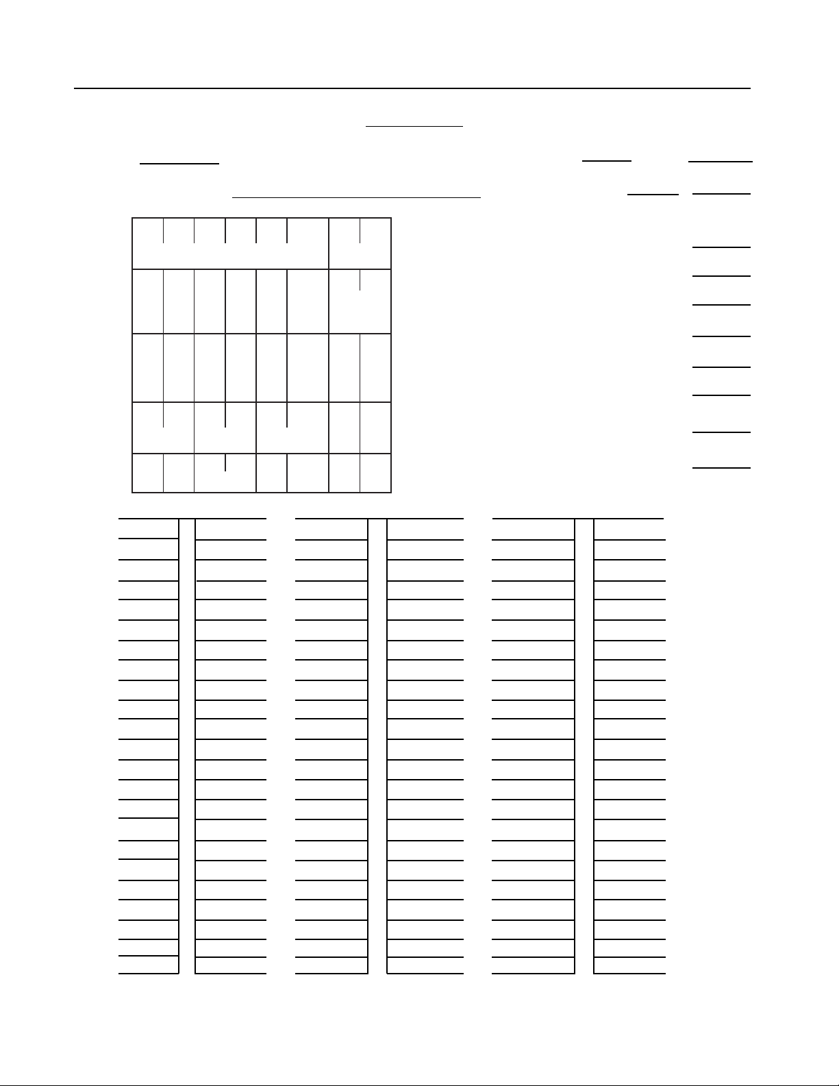
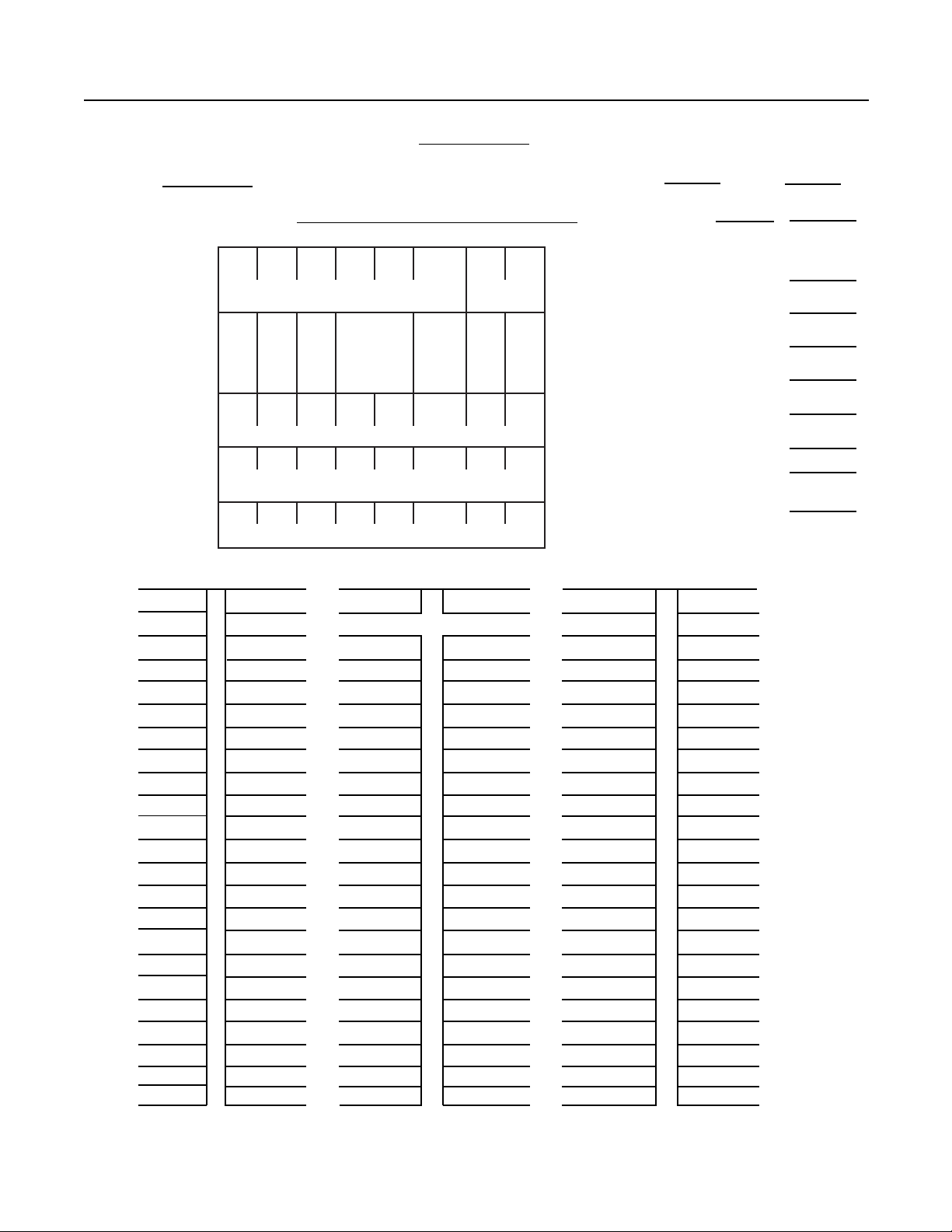
In addition, the typical internal module to
module wiring of two control panels is shown
on pages 2 and 3 in the form of typical Wire
Lists. Either a wiring list of this type or a
complete point to point wiring diagram should
be furnished with every system and should be
kept as on-board documentation for future
reference in system service and maintenance.
NOTE: When designing Fire Control Systems
for various types of vessels, the designer
should be aware of the required vessel type,
domestic and SOLAS regulations applicable
for that vessel.
1
Page 7
Section I — Introduction
9-20 DWG E 315-085585 Sheet of
WIRE LIST
Name
87654 3 21
A
TYPICAL LARGE SYSTEM Job No.
Module Space
53-PC53-SP
UZ
UZ
UZ
UZ
UZ
B
53
53
53
53
ST
ST
ST
ST
UZ
UZ
SZ
C
53
53
ST
ST
D
MS
03
03
23-RS23-RS23-RS
E
33-KB
MM
53
53
ST
MR
LT
U03
U03
53-CB
EA
CM
U03
03
EA
U03
FROM TO FROM TO FROM TO
CP-36 C3-1 B5-7 D3-36
C3-1 C3-2 B6-1 D3-40
C3-2 C1-1 B6-7 D3-44
C3-3 C1-2 B7-1 D5-1
C2-5 C1-3 B7-7 D5-4
C1-3 CP-39 B8-1 D5-9
P5-5 D1-1 B8-7 D5-36
D1-1 C2-1 C8-1 D5-44
C2-1 C4-1 C7-1 D7-1
P5-6 D1-2 C7-7 D7-4
D1-2 C2-2
C2-2 C4-1
C6-1 C5-1
C5-1 C5-2
C5-2 D1-5
B2+ BATT+
B2- BATTC8-PIN5 CP-41
B4-1 D3-1
B4-7 D3-5
B5-1 D3-7
EK CP PS -
JP JS JS-
BM -
No. of BP - 30
2
Page 8
Section I — Introduction
WIRE LIST
9-20 DWG E 315-085585 Sheet of
Name
87654 3 21
A
TYPICAL SMALL SYSTEM Job No.
Module Space
53-PC53-SP
UZ
UZ
UZ
B
53
53
53
ST
ST
ST
C
D
E
CR
U03
UZ
UZ
UZ
53
53
53
ST
ST
ST
FROM TO FROM TO FROM TO
CP-41 BB-5
NOTE: RC-30U CONTROLS B6 THRU B8
EK CP PS -
JP JS -
JS BM -
No. of BP - 30
3
Page 9

SECTION II
POWER REQUIREMENTS
It is a US Coast Guard requirement that the
fire detection system have two sources of
power. Most large ships have both main
generators and emergency generators;
therefore, they can satisfy this requirement
by arranging to have power supplied to the
fire detection system by both the main and
emergency generators.
A US Coast Guard approved Power
Transfer Relay must be used for the
automatic transfer from main power to
secondary power when the main power
source has 15% to 20% potential variation.
The transfer to secondary power creates a
visual and audible trouble signal on the CP35 Control Panel. The Model PTR-1 Power
Transfer Relay from Siemens Industry, Inc.
has been designed for this purpose and is
US Coast Guard approved.
In cases where there are no emergency
generators, battery backup power to the
system is required. Revised US Coast
Guard regulations have reduced the
required battery operation time to 36 hours
for passenger ships and 18 hours for all
other types of vessels. In cases where it is a
desired option to furnish the fire detection
system with standby battery power, even
when there are main and emergency
generators supplying the system, there is no
specific battery operation time period,
although it would be recommended to be a
minimum of 18 hours.
When the smoke detection system is
furnished with battery backup power, it is
necessary to calculate the system power
requirements to determine the battery
ampere-hour capacity necessary. The
calculations can be done on the Power
Calculation Sheet (page 24) and the Battery
Curves shown on pages 26 and 27. Another
requirement involving battery power is that a
voltmeter and ammeter (MM-35) are
furnished. The voltmeter and ammeter are
not required when the batteries are used as
a third power source.
4
Page 10

1. MODULES
SECTION III
EQUIPMENT DESCRIPTIONS
AND FUNCTIONS
CP-35 MAIN CONTROL UNIT
This control unit contains system power,
alarm and trouble indicating lamps, lamp
test/reset, trouble and subsequent alarm
silence switches, one supervised 1.5A
audible alarm circuit, and two detection
zones not to be used for US Coast Guard
approved systems because these zones do
not have alarm and trouble test switches.
(See Spec Sheet Catalog No. 3060 for
terminal identification.)
PS-35 POWER SUPPLY
This 10A power supply converts the 115
VAC, 60 or 50 Hz and supplies 24 VDC to
all modules in the System 3 Control Panel.
(See Spec Sheet Catalog No. 3061 for
additional details.)
BC-35 BATTERY CHARGER MODULE
This module is required to automatically
transfer power from normal power to battery
power and also to charge the batteries. It
can charge battery sizes up to 25 amperehours, and the charging capacity can be
increased in increments of 25 AH to a limit
of more than 100 AH by use of the BE-35;
see below. (See Spec Sheet Catalog No.
3177.)
BE-35 BATTERY EXTENDER
MODULE
This extender module increases the 25 AH
charging capability of the BC-35 by another
25 AH when larger batteries are required,
based on a 48 hour recharge period, as per
ULI requirements. (See Spec Sheet Catalog
No. 3177.)
MM-35 METER MODULE
This module includes the US Coast Guard
required voltmeter and ammeter to display
battery voltage and charging current when
batteries are used as the second power
source. The meters are not required when
battery power is a third power source. (See
Spec Sheet Catalog No. 3355.)
TC-30U BATTERY TRANSFER
MODULE
This module is required to use separate
ship battery power when available. Ship
battery power would have its own charging
method.
5
Page 11

Section III — Equipment Descriptions and Functions
ZU-35TS ZONE MODULE
This module includes two detection zones
with alarm and trouble LEDs, test switches,
and output terminals to activate other
appropriate modules or remote annunciators. It can accommodate up to thirty
ionization, photoelectric, or flame detectors,
or a combination thereof. The number of
thermal
detectors, manual stations, and other
approved contact devices that can be wired
on a single zone are under practical limitations only. (See Spec Sheet Catalog No.
3107.)
ZS-30 INTRINSICALLY SAFE ZONE
MODULE (See NOTE on page 15.)
This module allows certain ionization
detectors, thermal detectors, and manual
stations of the non-explosionproof type to
be installed in hazardous areas classified
as Class I, Division I, Groups A, B, C, and
D. A diode shunt barrier is required outside
the hazard area to limit the energy in the
event of equipment failure. Only ten Model
DI-3IS Ionization Detectors or five Model
S-121/122 Flame Detectors, and any
number of approved thermal detectors or
manual stations, can be connected to this
single zone module. (See Spec Sheet
Catalog No. 3105.)
Note: Unlike the ZU-35TS, this single
zone module does not have its
own zone alarm and trouble test
switches. Therefore, it is
necessary to use an SM-30 switch
module alongside the ZS-30 to
satisfy this test capability
requirement.
RC-30U CONFIRMATION MODULE
This module is designed to reduce unwanted
alarms from the momentary presence of
products of combustion — low ceiling heights
where smoking is allowed, for example. It
records the first alarm from zones under its
control, but does not put the control panel into
the alarm mode unless the detector response is
repeated within 1 minute (time adjustable) or
less. (See Spec Sheet Catalog No. 3167.)
AE-30U ALARM EXTENDER MODULE
This module is used whenever the total alarm
device power exceeds the supervised 1.5A alarm
circuit that is included in the CP-35, or where
separate alarm circuits are required. Each
AE-30U offers another supervised 1.5A, and
AE-30U modules can be used in whatever
multiples are required. (See Spec Sheet
Catalog No. 3129.)
MC-30 MASTER CODE MODULE
This module is designed to provide a pulse
(120/minute) on the audible and visible signal
devices. It is capable of controlling up to three
audible signal circuit AE-30U modules. (See
Spec Sheet Catalog No. 3163.)
ZN-31U CONTACT MODULE
See Spec Sheet Catalog No. 3108.
ZN-34UA, ZN-34US INPUT MODULES
These modules are designed to provide two
circuits for the supervision of sprinkler system
gate valves and ancillary equipment in accordance with NFPA Standard 72. The modules
provide two yellow LED indicators per circuit. The
first illuminates when a supervisory condition
exists and the second when a circuit trouble
condition occurs. The module utilizes an end-ofline resistor in parallel with normally open
switches to provide this supervision. (See Spec
Sheet Catalog No. 3111.)
6
Page 12

2. SUPPLEMENTARY MODULES
Section III — Equipment Descriptions and Functions
SR-30 RELAY MODULE
This module has two SPST relays with 3A
contacts. (See Spec Sheet Catalog No.
3121.)
SR-32 RELAY MODULE
This module has six DPDT relays with 3A
contacts. (See Spec Sheet Catalog No.
3125.)
SR-35 RELAY MODULE
This module has eight SPDT relays with 2A
contacts. (See Spec Sheet Catalog No.
3130.)
TL-30U TIME LIMIT MODULE
This module is designed to provide any
required timing function (time in or time out)
with field adjustment possible between 1
second and 10 minutes. (See Spec Sheet
Catalog No. 3166.)
SM-30 SWITCH MODULE
This module provides two manual on/off
switches that can be used for any desired
purpose. The switches put the system into a
trouble condition and use LED trouble lights
to identify which switches are switched to
off-normal. (See Spec Sheet Catalog No.
3162.)
RM-30U and RM-30RU RELEASE
MODULES
These modules are designed to provide a
supervised 1.5A release circuit for damper
release or similar functions. They both have
a 24 VDC output, but the RM-30RU includes
three series resistors that can adjust for 6, 12,
18, or 24 VDC resistance. (See Spec Sheet
Catalog No. 3162.)
DM-31 DISTRIBUTION MODULE
This module is a terminal strip for use when
multiple enclosures are required on large
systems. (See Drawing 515-021941 in
Appendix.)
AD-30S SUPERVISED ANNUNCIATOR
DRIVER
This module is designed to be installed with
other modules in the System 3 Control Panel.
The AD-30S is a supervised annunciator driver
module which will supervise groups of 8
indicators and the wires going to these
indicators. If you required 1 supervised, 8-zone
annunciator, you would require 1 AD-30S.
However, if you required a 24 zone supervised
annunciator, then 3 AD-30Ss would be needed
to drive the annunciator.
PM-31 and PM-32 PROGRAM
MATRIX MODULES
These two modules are designed to provide
complex supplementary control that would
be difficult to arrange with relays. (See Spec
Sheet Catalog No. 3169.)
7
Page 13

Section III — Equipment Descriptions and Functions
3. ENCLOSURES
EA-32, EA-33, and EA-35 ENCLOSURE
The selection of the required number of modules
for a given system determines the necessary
enclosure size. The enclosure model number
indicates the number of module rows: the EA-32
has two, the EA-33 has three, and the EA-35 has
five. Each module row contains eight module
spaces, but some modules require more than
one space. On large systems it may be desirable
or necessary to use more than one enclosure.
This can be accomplished through the use of the
DM-31 distribution module, which is used as a
terminal strip.
SHOCK MOUNTING FOR ENCLOSURES
All enclosures should be shock mounted and drip
proof with an upper door shroud and Lexan
window lenses. A US Coast Guard approval
nameplate must be affixed to the door. (See Spec
Sheet Catalog No. 3325 for sizes and dimensions
and pages 8-9 for shock-mount and drip-proof
shroud installation.)
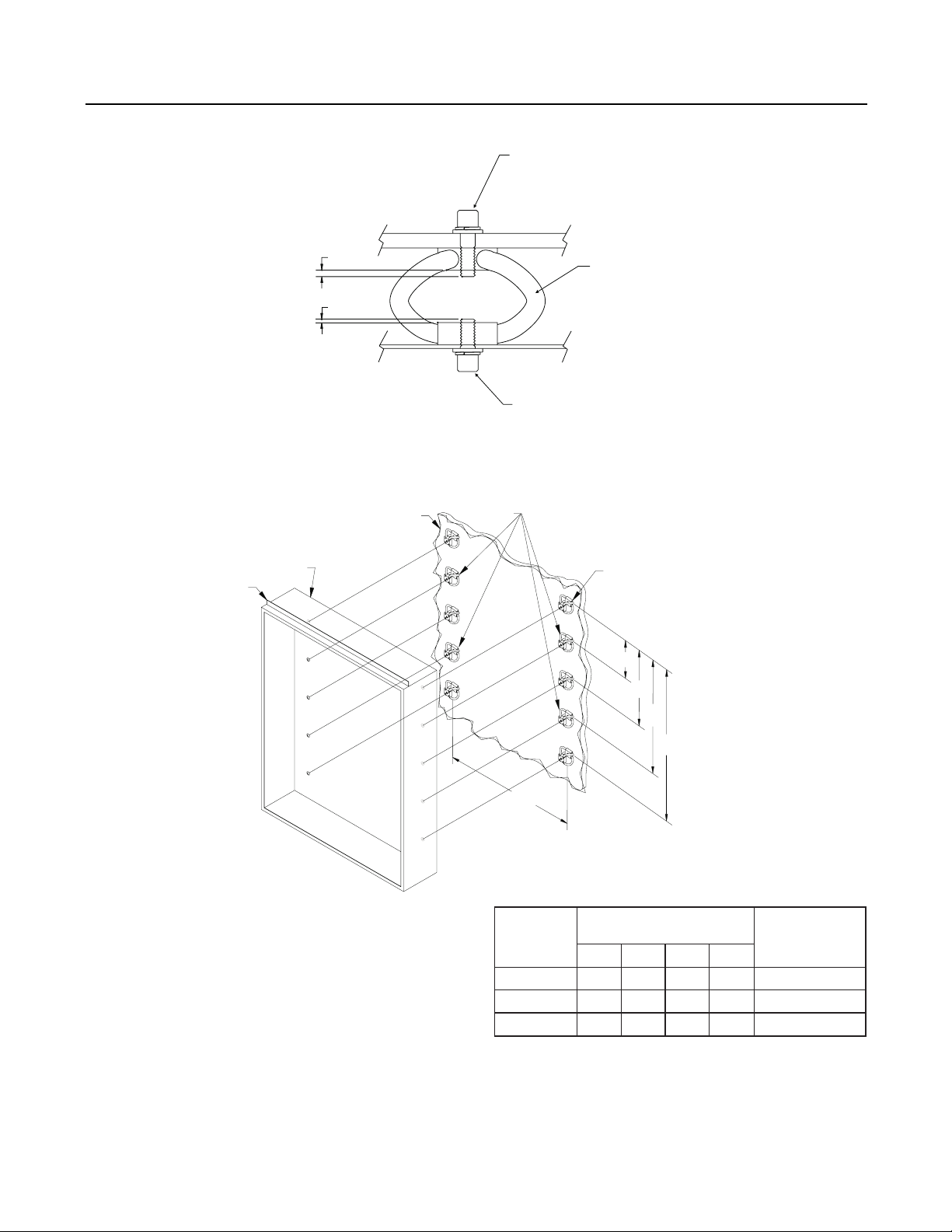
ASSEMBLY INSTRUCTIONS FOR COAST
GUARD MOUNTING KIT VIK-1
1. On the Table on page 9 locate the
enclosure model to be installed. Determine
the number of isolators to be used and the
distance between the isolator centers.
2. Mark isolator centers to be used on the
bulkhead and draw perpendicular lines
through each of the centers.
3. Drill 5/16 inch clearance holes into bulk-head.
Mount isolator to bulkhead with 1/4-20x3/4"
cap screw, washer and lockwasher. Tighten
to 13 ft-lbs of torque. Refer to the stud
assembly illustration (Figure 1, page 9) for
the proper hardware sequence.
4. Mount the enclosure to the isolators (Refer to
the Mounting Diagram, Figure 2, page 9) with
1/4-20x1/2" cap screw, washer and
lockwasher. Tighten to 13 ft-lbs of torque.
NOTES: Flexible conduit or cable with a
maximum diameter of 3/4 inch and a
minimum length of 18 inches from a
rigid connection should be used to
house external wiring.
PTR-1 POWER TRANSFER RELAY
The PTR-1 is an automatic power transfer relay
that transfers power from the main generators, at
a 15% to 20% potential reduction, to the backup
generators. This automatic transfer creates an
audible and visual system trouble signal. The
PTR-1 is in its own enclosure. (See Appendix for
PTR-1 Connections, Cover, and Enclosure.)
8
Page 14
Section III — Equipment Descriptions and Functions
#1/4-20 SOCKET HEAD
CAP SCREW 3/4" LONG
#1/4 FLAT WASHER
#1/4 INTERNAL LOCKWASHER
(USE FLAT WASHERS UNDER
HEAD TO MEET MAX 2
THREAD REQUIREMENT)
Note:
The VIK-1 Kit can only be used
on bulkheads with a thickness
of no greater than 5/16 inch.
VIBRATION ISOLATOR DETAIL: COAST GUARD APPLICATION
EA-32, -33 or -35
DRIP-PROOF
SHROUD
MAX
2 THREADS
MAX
2 THREADS
BULKHEAD
BULK HEAD
Figure 1
EA-35 ONLY
VIBRATION
ISOLATOR
#1/4-20 SOCKET HEAD CAP
SCREW 1/2" LONG
#1/4 FLAT WASHER
#1/4 INTERNAL LOCKWASHER
ISOLATOR
A
B
Note:
1. Prior to mounting enclosure EA-35, drill four new
5/16 inch diameter holes located vertically at the A
and C dimensions, in addition to redrilling the
existing mounting holes to 1/2 inch.
MOUNTING DIAGRAM FOR EA-32, -33, AND -35 ENCLOSURES
FOR COAST GUARD APPLICATION
Figure 2
C
D
20 7/8”
ERUSOLCNE
EZIS
ABCD
23 ——— ½024
33—½51—136
533162932501
RETNEC
)SEHCNI(ECNATSID
ROTALOSIFO.ON
DERIUQERSTIK
9
Page 15
Section III — Equipment Descriptions and Functions
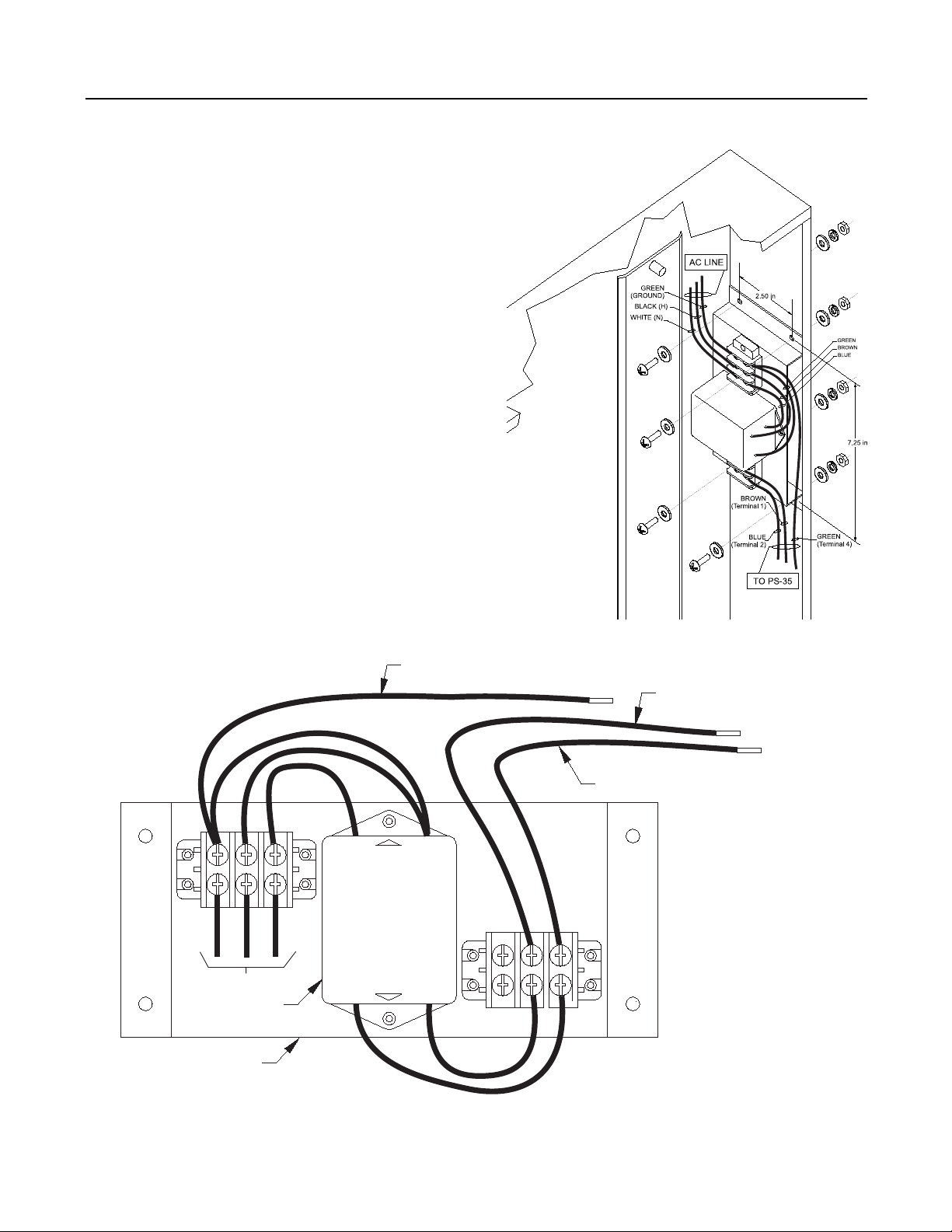
INSTALLING THE CGFK-1 FILTER KIT
1. Using the bracket as a template, hold the
bracket up against the upper right-hand side
of the enclosure, close to where the PS-35 is
mounted. (Refer to Figure 3-Mounting.)
2. Mark the location of the four holes in the
bracket on the side of the enclosure.
3. Drill four 0.18" diameter holes in the locations
marked on the side of the enclosure.
4. Mount the bracket assembly using the #8-32
screws, flat washers, lock washers and nuts
as shown in Figure 3-Mounting.
5. Insert the AC line wires into the positions
shown in Figure 3-Wiring.
6. Snap the terminal block covers into place.
7. Connect the filter load wires from the filter
to the PS-35 terminal block as shown in
Figure 3-Wiring.
BROWN
GREEN
HOT
GROUND
AC LINE
FILTER BRACKET
BLUE
FILTER
NEUTRAL
GREEN WIRE (24" LONG)
TO PS-35, TERMINAL 4
LINE
CORCOM
EMI FILTER
P/N 10VR3
LOAD
BROWN
BLUE WIRE (24" LONG)
TO PS-35, TERMINAL 2
BLUE
(MOUNTING)
BROWN WIRE (24" LONG)
TO PS-35, TERMINAL 1
10
(WIRING)
Figure 3
INSTALLING THE CGFK-1 FILTER KIT
Page 16

4. REMOTE ANNUNCIATION
Section III — Equipment Descriptions and Functions
RL REMOTE ALARM LAMPS SERIES
This series of remote alarm lamps was
designed to offer fast and convenient
identification of any detectors that release
alarms within concealed spaces such as
staterooms, store rooms, lockers, etc. The
RL-30 and RL-40 models are used as remote
individual detector alarm lamps on round or
rectangular switch boxes, respectively. The
RL-6 can accommodate up to four detectors
with one common remote indication. (See Spec
Sheet Catalog No. 8011 and No. 8013.)
5. AUDIBLE ALARMS
ALARM LOCATIONS AND
REQUIREMENTS
Ten inch bells are required to sound in the
following locations when any alarm initiating
device is actuated.
1. Alarm bell must always sound on the bridge
regardless of which zone is in alarm.
2. Alarm bells must sound in the engine room,
machinery spaces, and the control room
when the alarm is initiated in any of these
spaces. In case the control room might be
unattended at the time of alarm, bells must
also be installed in the passageways and
lounge areas of the licensed engineer’s
quarters.
RLP REMOTE LAMP PANELS SERIES
The RLP-4, -8, and -12, with 4, 8, and 12
lamps, respectively, serve the same purpose
as the individual remote alarm lamps, except
that they are mounted on a common panel.
(See Spec Sheet Catalog No. 8012.)
NOTE: If it should be necessary to
supplement the 10 inch bell audible output in
high noise background areas with horns,
sirens, strobes, flashing or rotating lights,
the wiring to such supplementary alarm
devices does not have to be supervised.
However, audible alarms other than bells
must always be accompanied by lights or
strobes.
BT-F and BT-SS Bells
The BT-F and BT-SS are vibrating and single
stroke 10-inch bells. (See Spec. Sheet
Catalog No. 2537.)
3. If an alarm is not acknowledged (silenced or
reset) at the control panel within 2 minutes,
the control panel must automatically cause
the General Alarm to sound.
11
Page 17

Section III — Equipment Descriptions and Functions
SUMMARY OF AUDIBLE ALARMS*
Model Min. dB Current Normal Limit
Number Level@10 Ft. Draw@24VDC Per Circuit
BT-F 84.4 288mA 5
BT-SS 74.7 318mA 4
HN-EP 82 65mA 23
HNH-EP 92 350mA 4
U-EC(-W) 68.1 19mA 78
U-EC-MCS(-W)
Chime only 92 19mA 78
15cd Strobe only 82mA 18
30cd Strobe only 107mA 14
75cd Strobe only 182mA 8
110 Strobe only 234mA 6
Chime/15cd Strobe 92 101mA 14
Chime/30cd Strobe 92 126mA 11
Chime/75cd Strobe 92 201mA 7
Chime/110cd Strobe 92 253mA 5
U-HN(-W) 80.4 49mA 30
U-HN-MCS(-W)
Horn only 80.4 49mA 30
15cd Strobe only 82mA 18
30cd Strobe only 107mA 14
75cd Strobe only 182mA 8
110 Strobe only 234mA 6
Horn/15cd Strobe 92 131mA 11
Horn/30cd Strobe 92 156mA 9
Horn/75cd Strobe 92 231mA 6
Horn/110cd Strobe 92 283mA 5
U-HNH(-W) 82.6 70mA 21
U-HNH-MCS(-W)
Horn only 82.6 70mA 21
15cd Strobe only 82mA 18
30cd Strobe only 107mA 14
75cd Strobe only 182mA 8
110 Strobe only 234mA 6
Horn/15cd Strobe 92 152mA 9
Horn/30cd Strobe 92 177mA 8
Horn/75cd Strobe 92 252mA 5
Horn/110cd Strobe 92 304mA 4
U-MH(-W)
Steady 79.2 18mA 83
Temporal 75.9 16mA 93
U-MH-1G(-W)
Steady 79.2 18mA 83
Temporal 75.9 16mA 93
U-MH-MCS(-W)
Horn only 79.2 18mA 83
15cd Strobe only 82mA 18
30cd Strobe only 107mA 14
75cd Strobe only 182mA 8
110 Strobe only 234mA 6
Horn/15cd Strobe 92 100mA 15
Horn/30cd Strobe 92 115mA 13
Horn/75cd Strobe 92 200mA 7
Horn/110cd Strobe 92 252mA 5
U-MHT(-W)
Steady 79.2 18mA 83
Temporal 75.9 16mA 93
U-MHT-MCS(-W)
Horn only 79.2 18mA 83
15cd Strobe only 82mA 18
30cd Strobe only 107mA 14
75cd Strobe only 182mA 8
110 Strobe only 234mA 6
Horn/15cd Strobe 92 100mA 15
Horn/30cd Strobe 92 115mA 13
Horn/75cd Strobe 92 200mA 7
Horn/110cd Strobe 92 252mA 5
Model Min. dB Current Normal Limit
Number Level@10 Ft. Draw@24VDC Per Circuit
U-MMT(-W)
Horn 80.4 53mA 28
Chime 73.9 53mA 28
Bell 74 52mA 28
Sl Whoop 77.8 67mA 22
Temporal 76.2 38mA 39
Siren 78.5 67mA 22
Hi-Lo 78.6 38mA 39
SS Bell 71.1 44mA 34
U-MMT-1G(-W)
Horn 80.4 53mA 28
Chime 73.9 53mA 28
Bell 74 52mA 28
Sl Whoop 77.8 67mA 22
Temporal 76.2 38mA 39
Siren 78.5 67mA 22
Hi-Lo 78.6 38mA 39
SS Bell 71.1 44mA 34
U-MMT-MCS(-W)
Horn only 80.4 53mA 28
Chime only 73.9 53mA 28
Bell only 74 52mA 28
Sl Whoop only 77.8 67mA 22
Temporal only 76.2 38mA 39
Siren only 78.5 67mA 22
Hi-Lo only 78.6 38mA 39
SS Bell only 71.1 44mA 34
15cd Strobe only 82mA 18
30cd Strobe only 107mA 14
75cd Strobe only 182mA 8
110 Strobe only 234mA 6
Horn/15cd Strobe 80.4 135mA 11
Horn/30cd Strobe 80.4 160mA 9
Horn75cd Strobe 80.4 235mA 6
Horn/110 Strobe 80.4 287mA 5
Chime/15cd Strobe 73.9 135mA 11
Chime/30cd Strobe 73.9 160mA 9
Chime75cd Strobe 73.9 235mA 6
Chime/110 Strobe 76.9 287mA 5
Bell/15cd Strobe 74 134mA 11
Bell/30cd Strobe 74 159mA 9
Bell/75cd Strobe 74 234mA 6
Bell/110 Strobe 74 286mA 5
Sl Whoop/15cd Strobe 77.8 149mA 10
Sl Whoop/30cd Strobe 77.8 174mA 8
Sl Whoop/75cd Strobe 77.8 249mA 6
Sl Whoop/110 Strobe 77.8 301mA 4
Temporal/15cd Strobe 76.2 120mA 12
Temporal/30cd Strobe 76.2 145mA 10
Temporal/75cd Strobe 76.2 220mA 6
Temporal/110 Strobe 76.2 272mA 5
Siren/15cd Strobe 78.5 149mA 10
Siren/30cd Strobe 78.5 174mA 8
Siren/75cd Strobe 78.5 249mA 6
Siren/110 Strobe 78.5 301mA 4
Hi-Lo/15cd Strobe 78.6 120mA 12
Hi-Lo/30cd Strobe 78.6 145mA 10
Hi-Lo/75cd Strobe 78.6 220mA 6
Hi-Lo/110 Strobe 78.6 272mA 5
SSBell/15cd Strobe 71.1 126mA 11
SSBell/30cd Strobe 71.1 151mA 9
SSBell/75cd Strobe 71.1 226mA 6
SSBell/110 Strobe 71.1 278mA 5
*When audible alarms other than required bells
are used, they must be accompanied with a
visual fire signal either incorporated in the horn
enclosure or separate strobes.
12
Any combination of the approved notification
devices can be used, but the combination cannot
be greater than the circuit current of 1.5A.
Page 18

6. INITIATING DEVICES—
AUTOMATIC
Section III — Equipment Descriptions and Functions
DI-3
Ion detector— limit of thirty per zone. (See
Spec Sheet Catalog No. 6119.)
Dl-3IS
This ion detector is for intrinsically safe
applications when used with the ZS-30
module with diode shunt barrier. There is a
limit of ten detectors per zone circuit. (See
Spec Sheet Catalog No. 6119.)
DT-C Series
The DT-135CS and DT-200CS thermal
detectors are the rate compensated type
available in 135° F and 200° F settings. The
DT-135CL and the DT-200CL are identical to
CS versions, except that they have an
internal alarm indicating lamp. There is a
practical limit only to the number per zone.
(See Spec Sheet Catalog No. 6131.)
DT-11 Thermal Detector
The DT-11 is a thermal detector for use in
open areas. It uses the DB-11 low profile
surface mounting base or the DB-3S base
with the DB-ADPT adapter. (See Spec
Sheet Catalog No. 6174.)
DT-135/200 WP
DT-140/190 EP
This explosionproof thermal detector has a
rate compensated principle available in
either a 140° F and 190° F setting. It should
be used in hazardous areas requiring
explosionproof devices. The detector
mounts to an approved explosionproof
junction box. (See Spec Sheet Catalog No.
6128.)
PE-11 Photoelectric Detector
The PE-11 is a photoelectric detector that
responds to a wide range of both flaming
and smoldering fire conditions. It uses the
DB-11 low profile surface mounting base,
the DB-3S base with the DB-ADPT adapter,
or the AD-11P/PR air duct housing. (See
Spec Sheet Catalog No. 6173.)
PE-11T Photoelectric Detector with
Heat Sensor
The PE-11T is a photoelectric detector with
heat sensor that responds to a wide range
of both flaming and smoldering fire conditions. It uses the DB-11 low profile surface
mounting base or the DB-3S base with the
DB-ADPT adapter. (See Spec Sheet Catalog No. 6173.)
This weatherproof thermal detector has a
rate compensated principal available in
either a 135° F or 200° F setting. The detector is epoxy coated and mounts to a weatherproof box for approved use in wet or
unsheltered locations. (See Spec Sheet
Catalog No. 6127.)
13
Page 19
Section III — Equipment Descriptions and Functions
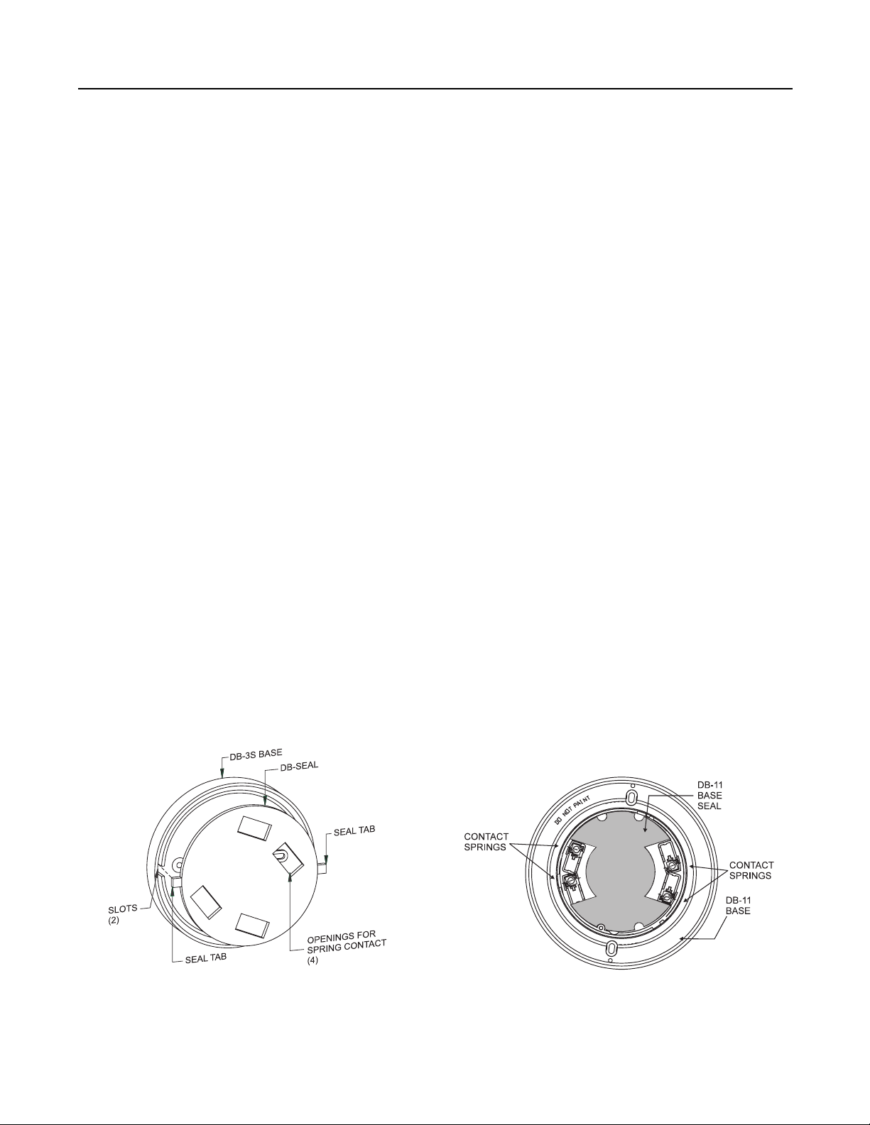
6.1 BASE SEAL for DB-3S or DB-11 BASE
Use the DB-Seal with a DB-3S base or the DB-11 Seal with a DB-11 base to prevent moisture from
condensing and collecting on the rear of the detector used. This moisture can occur when units experience different temperatures or humidity conditions.
INSTALLING the DB-SEAL for DB-3S BASE
(See Figure 4)
All wiring must comply with national and local
codes.
1. Install and wire the DB-3S base by following
the DB-3S Installation Instructions
(P/N 315-083225). Make sure that all wires
are dressed flush to the bottom of the base.
2. Position the tabs on the seal over the slots in
the inner rim of the base and press the seal in
place.
3. Check that the four openings for the spring
contacts clear the springs and the plastic
terminal supports.
4. With the seal in place, install the detector.
5. Follow the checkout procedure in the detector
installation instructions.
INSTALLING the DB-11 SEAL for DB-11 BASE
(See Figure 5)
All wiring must comply with national and
local codes.
1. Install and wire the DB-11 base by following
the DB-11 Installation Instructions
(P/N 315-094193). Make sure that all wires
are dressed flush to the bottom of the base.
2. Place the base seal (1/4" white foam) firmly
into the bottom of the base. Do not cover the
contact springs (See Figure 5.)
3. Rotate the detector counterclockwise while
pressing on it until the detector drops into the
base.
4. Rotate the detector clockwise until it stops
and locks in place.
14
Figure 4
Installing the DB-Seal
Figure 5
Installing the DB-11 Seal
Page 20

7. INITIATING DEVICES — MANUAL
Section III — Equipment Descriptions and Functions
MS-51/501
Manual fire alarm station. Manual stations are
recommended for use with automatic fire
detectors. If a fire is observed before automatic
detector response, the manual activation of the
station results in the same system response as
automatic detection. Manual stations should be
installed throughout the accommodation spaces,
the service spaces, and the control stations.
One manual station should be located at each
exit. The stations should be readily accessible
in the corridors of each deck so that no part of
the corridor is more than 60 feet (20 meters)
from another manual station. (See Spec Sheet
Catalog No. 6183.)
MSM Series
The MSM Series manual stations feature a
rugged diecast metal housing that satisfies
both architectural and code requirements
for manual fire alarm box initiation devices.
The MSM-Series box features keyed reset
using the same key as the control panels.
The MSM Series models are low-profile
with all surfaces either painted or plated to
inhibit corrosion. These boxes have raised
lettering and are shipped with two reset
keys and a break glass rod (use of rod is
optional.) Options include: double action,
institutional, weatherproof, and explosionproof. (See Spec Sheet Catalog No. 6184.)
15
Page 21

SECTION IV
CONTROL PANEL CONFIGURATION
After the type and quantity of modules
required to satisfy a given system are
determined, the arrangement of the modules in the enclosure(s) should be planned.
For consistency, the CP-35 control unit
must always be located in the left side of
the top row, with the PS-35 on the right
side of the row to fill the entire top row.
If the system does not require battery
backup, the remaining modules can be
located as desired, except for the RC-30U,
as the others are not placement sensitive. If
battery backup is to be included, the BC-35
battery charger module must always be
placed to the right side of the second row.
Should one or more BE-35 battery extender
modules be required, they must be placed
to the left of the BC-35. The BE-35 extends
the 25 AH charging capability of the BC-35
by another 25 AH up to a final capability of
more than 100 AH. The MM-35 meter
module should then be placed to the left of
the BC-35 or next to the last BE-35. The
remaining modules can be placed as
desired.
16
Page 22

DETECTOR APPLICATION AND SP ACING
1. SMOKE DETECTORS
SECTION V
1.1 DESCRIPTION AND FUNCTION
Smoke detector is the generic name given
to either ionization type or photoelectric type
detectors. The ionization type responds to
both visible and invisible products of combustion, while the photoelectric type depends on sensing visible smoke.
1.2 SPACING
For average areas with smooth ceilings and
normal air movement, the maximum recommended spacing is 900 square feet or no
more than 30 feet between centers and 15
feet from a sidewall. In areas with higher air
movement, the detector spacing should be
reduced accordingly.
2. THERMAL DETECTORS
2.1 DESCRIPTION AND FUNCTION
All thermal detectors respond only to excessive heat, which is assumed to be generated
from a flaming fire. The detectors are designed with different operating principles as
described below.
1.3 APPLICATION LIMITATIONS
1.3.1 On ceiling heights below 8 feet, the
possibility of unintentional alarms from
tobacco smoke does exist, especially in
areas where people might congregate. It is
recommended that smoke detectors in such
areas have their zones wired through the
RC-30U alarm confirmation module.
1.3.2 Smoke detectors should not be used
in areas where they could be subjected to
steam or moisture condensation such as in
galleys, laundries, etc. Thermal detectors
should be used in such areas.
2.2 SPACING
Maximum approved spacing of thermal detectors
is as follows:
Maximum
Area Protected Distance from
Type (Square Feet) Sidewalls (Feet)
2.1.1 Fixed Temperature
The air temperature has to exceed the set
ratings of the devices in order to activate it.
The settings are 135° F, 190° F, and higher
(on special order).
2.1.2 Rate Compensated
This type of thermal detector is similar to the
fixed temperature detector in operation, but is
compensated to eliminate the expected
thermal lag and, therefore, responds faster.
Fixed Temperature (DT-11) 625 (25 X 25) 12.5
Fixed and
Rate of Rise 2500 (50 X 50) 25
DT-135 CS, CL, and WP
Rate Compensated 2500 (50 X 50) 25
DT-200 CS, CL and WP
Rate Compensated 2500 (50 X 50) 12.5
17
Page 23

Section V — Detector Application and Spacing
3. PLANNING A FIRE DETECTION SYSTEM
When planning a fire detection system, make
a choice of detector based on the kinds of
fires expected. The type and quantity of fuel,
possible ignition sources, ranges of ambient
conditions, and the value of the property to be
protected should all be considered.
In general, heat detectors have the lowest
cost and false alarm rate, but are the slowest
to respond. Since the heat generated by small
fires tends to dissipate fairly rapidly, heat
detectors are best used to protect confined
spaces, or directly over hazards where flaming fires can be expected. They are usually
installed on a grid pattern at their recommended spacing distances or at reduced
spacing for faster response. The operating
temperature of a heat detector should be at
least 25° F above the maximum expected
ambient temperature in the area protected.
Smoke detectors cost more than heat detectors, but respond faster to fires. They are
better suited to protect large open spaces
than heat detectors because smoke does not
dissipate as rapidly as heat does in the same
size space. Smoke detectors are either
installed according to prevailing air current
conditions or on a grid layout.
Photoelectric smoke detectors are best
used in places where wire insulation or
other smoldering fires may be expected.
Ionization smoke detectors are useful
where fire would be expected to develop
into a small flaming condition soon after
pyrolysis.
Flame detectors offer extremely fast response, but warn of any source of radiation
in their sensitivity range. False alarm rates
can be high if this kind of detector is improperly applied. Because flame detectors
are “line of sight” devices, care must be
taken to ensure that they can see the entire
protected area and that they will not be
accidentally blocked by stacked material or
equipment. Their sensitivity is a function of
flame size and distance from the detector.
Although fairly expensive, they are wellsuited to protect areas where explosive or
flammable vapors or dusts are encountered
because they are usually available in
explosionproof housings or have intrinsically safe ratings.
NFPA 72 Annex A (2002 Edition) has more
specific information on the installation of the
various types of detectors.
18
Page 24

Section V — Detector Application and Spacing
3.1 DETECTOR APPLICATION
In view of the problems that can be expected with the misapplication and location of detection devices
aboard ship, the guidelines below should be followed when designing systems.
These tables list situations where the use of smoke detectors, ionization and photoelectric should be
avoided.
MOISTURE
Salt water spray Heat treating
Corrosive atmospheres Dust or lint
Water spray Sawing, drilling and grinding
Live steam Pneumatic transport
Steam tables
Showers
Humidifiers
Slop sinks
Humid outside air
Excessive tobacco smoke
COMBUSTION PRODUCTS AND FUMES
Cooking equipment Engine exhaust
Ovens Gasoline forklift trucks
Dryers Diesel trucks and locomotives
Exhaust hoods Engines not vented to the outside
Metal cutting Welding and brazing
Machining Heating element, abnormal
Paint spray Dust accumulation
Curing Improper exhaust systems
Chemical fumes Incomplete combustion
Cleaning fluids
Conventional photoelectric/ionization detectors shall not be installed in cargo holds and
RO/RO spaces.
NOTE: Conventional weatherproof thermal detectors DT-135WP/DT-200WP must be
used in cargo holds and RO/RO spaces.
19
Page 25

Section V — Detector Application and Spacing
Areas to be Protected Monitoring Machinery Spaces
— ACCOMMODATION SPACES (ION,
PHOTO)
Halls, dining rooms, lounges, and other
areas of this type with permanent walls,
corridors, sanitation facilities, cabins,
offices, infirmaries, and leisure rooms not
containing cooking appliances.
— SERVICE AREAS (ION, PHOTO, TEMP)
Service cabinets, radio rooms,
strongrooms, stores, workshops other
than machinery spaces, and similar
areas, including shafts going to them,
as well as life-vest storage areas.
— SPECIAL AREAS (ION, PHOTO, TEMP)
Closed areas for transport of special
materials.
— SAFETY STATIONS (ION, PHOTO,
TEMP)
Areas housing the radio equipment, major
navigation equipment, standby
generator and central installations.
— MACHINERY SPACES (ION, PHOTO,
TEMP)
Areas housing the propulsion unit,
boilers, liquid-fuel handling units,
stabilization equipment, ventilation and
air conditioning equipment, and similar
areas, including the shafts running to them.
Because of the irregular shape of most
machinery spaces and the strong air
currents present, the number and type of
detectors used cannot be based on the
area protected, as is in the common
practice on land-based installations and
ship accommodation spaces. The best
design approach is to pick out all potential
fire outbreak areas and place a fire detector
above each of them at deck level. Areas of
potential fire risk include the following:
— Auxiliary boiler front
— Main boiler front
— Fuel oil pressure pumps
— Auxiliary generator sets
— Main diesel engine fuel oil pumps
and injectors
— Fuel oil purifiers
— Lubricating oil purifiers
— Fuel oil transfer pumps
— Workshops
— Electrical switchboards
— Storerooms
Locate additional detectors with fairly wide
spacing to give general cover to areas not
containing special risk.
20
Page 26

4. DETECTOR INSTALLATION
Section V — Detector Application and Spacing
After the most suitable detector for the job
is selected, the location of the detector
within the space to be protected should be
considered.
Spot type detectors are usually located on
the ceiling or side wall with the edge of the
detector located no closer than 4 inches
from the wall or ceiling. When heat detectors are installed at their listed spacing,
detection times are approximately equivalent to the operating time of standard 165° F
link-and-lever sprinklers. If faster response
is desired, reduce detector spacing. Also,
where ceiling heights exceed 16 feet, or
where ceiling construction is not smooth,
reduce spacings accordingly. Specific
information on the treatment of joisted,
beamed, and sloped ceilings can be found
in Annex A of NFPA 72 (2002 Edition).
When installing any type of heat detector,
consideration should be given to sources
of heat within the protected space which
might cause false alarms. For example,
locate heat detectors away from unit
heaters and ovens where surges of hot air
might be expected.
The installation of smoke detectors is more
critical than for heat detectors because
smoke transport is strongly influenced by
the convective air flow patterns within the
protected area. For this reason, smoke
detectors are not assigned a listed spacing
by the testing laboratories other than a
maximum area coverage of 900 square feet
per detector. Although a grid pattern can be
used as a starting point, care must be taken
to appropriately locate the heating supply
registers and return air registers. Smoke
detectors should be located away from
turbulence caused by hot air outlets. The
location of the smoke detectors should favor
return air because the return air draws
smoke toward the detector and because air
velocity at the return tends to be lower.
Smoke stratification also should be considered when smoke detectors are installed.
Smoke may stratify below a ceiling due to
temperature gradients or air flow along the
ceiling. When stratification is a possibility,
smoke detectors can be installed with alternate detectors at different levels.
The installation of ionization type detectors is
similar to that of smoke detectors since fire
gases tend to flow with smoke and are
similarly affected by convected flows within
the protected space. They also must be
located away from sources of oxidizable
gases or vapors; for example, away from
substances like aerosol sprays or hydrocarbon solvents, as these substances could
cause false alarms.
21
Page 27

Section V — Detector Application and Spacing
5. SYSTEM MAINTENANCE AND TESTING
All fire detection systems should be
periodically tested in a manner that ensures
at least one annual check of all associated
detectors and devices. The most effective
way to perform this system test is to check
one-twelfth of the number of initiating
devices monthly. This results in an automatic monthly test of the control panel,
alarm devices, and other associated
equipment.
More than just testing detectors for alarm
release, ionization and photoelectric-type
detectors should have their sensitivity
settings measured to assure a proper
range. All types of detectors should be
cleaned whenever there is evidence of dirt
or other contamination.
The System 3 Control Panel from Siemens
Industry, Inc. incorporates automatic
supervision of any open circuit or ground
fault in all external wiring. Either condition
results in a system audible and visual
trouble signal. Open circuits are further
identified by the LED on either the zone or
the audible alarm module in which they
exist. A ground fault, in addition to initiating
a system trouble, identifies itself with its own
indicating LED. To locate and correct the
ground fault, each external circuit is systematically opened until the fault signal is
cleared. The ground is then found in that
particular circuit.
System 3 zone modules (ZU-35TSs) include
manual momentary contact zone alarm and
zone trouble test switches that simulate an
alarm or trouble condition when actuated.
However, this type of testing does not
assure proper detector performances and
does not serve that purpose.
For more detailed troubleshooting and
maintenance information, refer to the
System 3 Installation and Maintenance
Manual, P/N 315-085063. For service
assistance, call the Siemens Industry, Inc.
offices or Authorized Distributor listings
found in the Yellow Pages.
22
Page 28

SECTION VI
POWER CALCULATIONS
1. POWER CALCULATION SHEET
The Power Calculation Sheet on the following page lists the
supervisory and alarm current requirements of the System 3
equipment and modules and can be used to determine the
power needs of a specific system configuration.
23
Page 29

Section VI — Power Calculations
POWER CALCULATION SHEET
MODULE QUANTITY SUPERVISORY (mA) ALARM (mA)
CP-35 __________ 150 __________ 2601__________
1
CP-35/BC-35 __________ 195 __________ 290
__________
BE-35 __________ 60 __________ — __________
AD-30S __________ 4/lamp __________ 50/lamp __________
AE-30U __________ 6.5 __________ 40 __________
MC-30 __________ 0 __________ 15 __________
RC-30U __________ 5 __________ 40 __________
RM-30U/30RU __________ 4 __________ 1600 __________
2
SR-30/32/35 __________ 0 __________ 45/relay
SM-30 __________ 0 __________ 45
__________
3
__________
TC-30U __________ 30 __________ 15 __________
TL-30U __________ 0 __________ 45 __________
4
ZS-30 __________ 50
ZU-35TS __________ 9/zone
__________ 100 __________
4
__________ 110/zone5__________
SUBTOTALS (a and b) a __________ b __________
Notification
Appliances __________ 0 c __________
TOTAL POWER REQUIREMENTS (a + b + c) __________
1 — Includes the CP-35 audible circuit.
2 — Use the highest number of relays that will be operated when either a) any three zones, or b) 10%
of the total zones are in alarm.
3 — Only when switch is operated.
4 — All zones must have supervisory current calculated.
5 — Minimum of three zones or 10% of total zones must be calculated.
In zones with shorting devices (thermals, MSs, etc.), add 120mA.
7 — Notification appliance alarm current draw.
8 — Total alarm current cannot exceed 10A when using the PS-35.
8
6
7
24
Page 30

2. DETERMINING CURRENT REQUIREMENTS FOR A
GIVEN SYSTEM CONFIGURATION
Section VI — Power Calculations
a. Following the format of the Power
Calculation Sheet above, list the
correct quantity for each type of
equipment included.
b. Multiply the supervisory and alarm
currents shown for each item by the
number of modules included, and list
the total module alarm currents in the
appropriate columns.
c. Add the two columns and record the
subtotals where indicated (a and b).
3. BATTERY BACKUP POWER
d. The current requirements of the
audible devices must also be calculated, based on number and type used.
Fill Blank c in with the amount of
current needed for the audible
devices included.
e. Add the current subtotals (a and b) to
the audible devices current requirements (c) to obtain the TOTAL current
necessary for the system. Enter that
amount opposite TOTAL.
The US Coast Guard requires that two
sources of power be available to the smoke
detection system. Usually this will be the main
and standby generators. Present requirements
for battery power as a second source call
for 36 hours for passenger ships and 18 hours
for all other ships. When battery backup is
optionally used in addition to main and
standby generators, there is no operation
time requirement, but 18 hours would be
recommended.
System 3 equipment includes two compatible
battery modules:
BT-33 5 AH Battery Module
BT-34 10 AH Battery Module
Batteries of 28 AH are also compatible with
System 3 systems, Model No. BTX-1. (See
Spec Sheet Catalog No. 3361.)
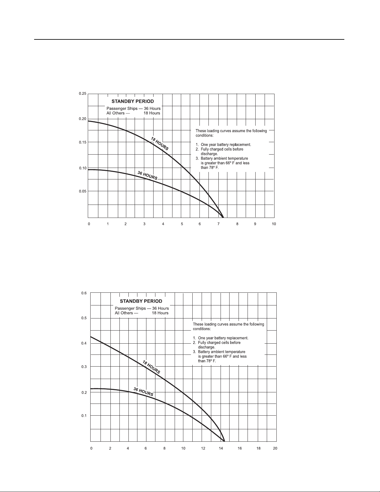
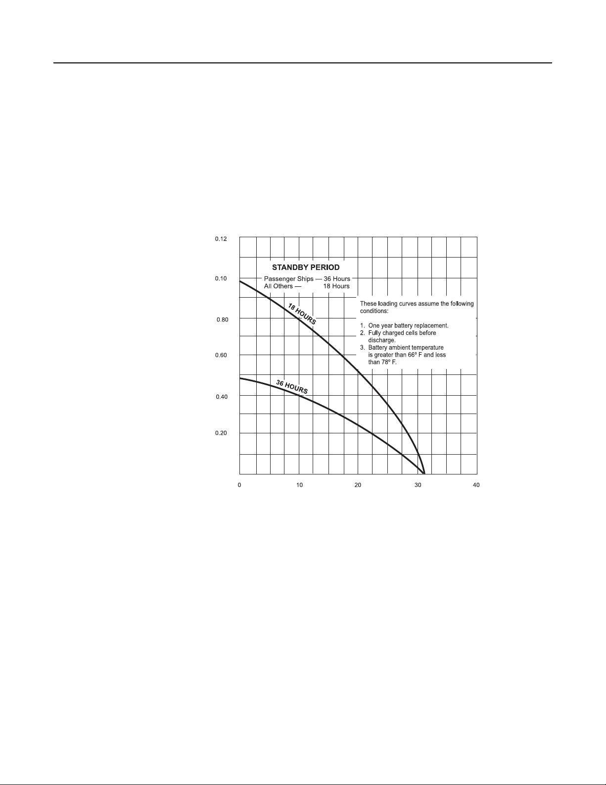
The following battery load curves show
alarm and supervisory current available
from 5 AH, 10 AH, and 28 AH batteries for
24 hour supervisory current and 5 minute
alarm current capabilities. The supervisory
current is represented on the vertical axis in
milliamps, and the alarm current, on the
horizontal axis in amps.
25
Page 31
Section VI — Power Calculations
Supervisory Current (mA)
CHART A
5 AH Rated Capacity at 20 Hour Rate
Allowable Supervisory and Alarm Currents
For Standby Periods of 18 Hours and 36 Hours
Alarm Duration 5 Minutes
10 AH Rated Capacity at 20 Hour Rate
Supervisory Current (mA)
Alarm Current (Amps)
CHART B
Allowable Supervisory and Alarm Currents
For Standby Periods of 18 Hours and 36 Hours
Alarm Duration 5 Minutes
26
Alarm Current (Amps)
Page 32
Section VI — Power Calculations
CHART C
28 AH Rated Capacity at 20 Hour Rate
Allowable Supervisory and Alarm Currents
For Standby Periods of 18 Hours and 36 Hours
Alarm Duration 5 Minutes
Supervisory Current (mA)
Alarm Current (Amps)
27
Page 33

Section VI — Power Calculations
4. DETERMINING BATTERY SIZE NECESSARY
FOR BACKUP POWER
a. Select the graph on Charts A, B, or C
that seems most appropriate for the
system configuration. Select the
correct battery curve, depending upon
whether the battery is needed for a
passenger ship (36 hours of battery
operation) or any other type of ship (18
hours).
b. Mark the needed supervisory current on
the Y- axis and draw a straight line
parallel to the X-axis between the point
marked and the appropriate curve of
the battery being considered.
c. Mark the needed alarm current on the X-axis
and draw a line parallel to the Y-axis between
that point and the appropriate curve of the
battery being considered.
d. If the intersection of these two lines falls
within the battery curve, that battery capacity
is sufficient to handle the system.
e. If the intersection point falls above the curve
or near the center of the curve, repeat the
calculations on the curve of either a larger or
smaller battery, as necessary, until the
necessary battery capacity is found.
28
Page 34

APPENDIX
A. COAST GUARD SYSTEM 3 TYPICAL DRAWING Drawing No. 315-085585
B. US COAST GUARD APPROVED EQUIPMENT LIST Cert No:161.002/17/8
C. PTR-1 CONNECTIONS, COVER,
AND ENCLOSURE (MOUNTING) Part No. 315-086284
D. DM-31 MODULE ASSEMBLY Part No. 515-021941
29
Page 35
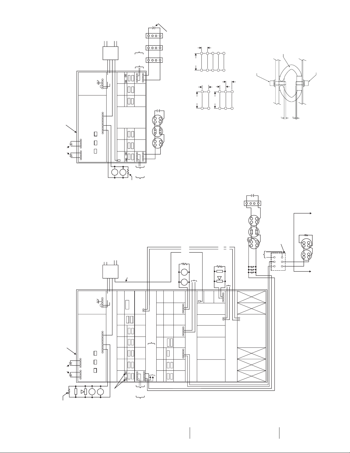
TYPICAL SMALL SYSTEM
(See Manual, P/N 315-086283, for description)
EA-32 ENCLOSURE
50uF, 50V CAPACITOR
SHOCK MOUNTED (SEE FIGURE 1)
P/N 100-115580
PS-35
CP-35
7 8 9 10 11 12
123456
TROUBLE
ALARM
LAMP
RESET
PTR-1
POWER
SILENCE
SILENCE
TEST
60
50
120V, / Hz
MAIN POWER
1
RELAY
TRANSFER
6
345
2
1
34 36 38 40 43
32
30
S3
S2
S1
2
567
MAIN
NEUTRAL
60
50
120V, / Hz
SECONDARY POWER
3
4
8
ZU-35TS
ZU-35TS
ZU-35TSRC-30U
ZU-35TS
ZU-35TS
ZU-
BELL
TO
ZONE 1
ZONE 2
12
AT TA
3
4
5
6
1
2
3
4
35TS
ZONE 5
ZONE 6
12
AT TA
BELL
5.6K, 1/2W
P/N 140-112166
EOL RESISTOR
TYPICAL FOR
MANUAL
_
+
789101112
_
+
7 8 9 10 11 12
TO
DET
TYPICAL
ZONES 3-6
MANUAL STATION
ZONE 2
STATION
123456
123456
ZONE
ZONES 1 -4
FOR DETECTOR
1
4
2
3
1
4
2
3
P/N 100-115580
1
_
+
50uF, 50V CAPACITOR
4
2
3
FIGURE 1
50uF, 50V
CAPACITOR
P/N 100-115580
6
1b
5
1a
PE-11
_
_
_
_
DT-CS
6
1b
5
DI-3
1a
_
+
ZONE 5
TYPICAL
MOUNT DETAIL
ENCLOSURE SHOCK
13
TYPICALLY
+
+
8
/
7
20
+++++
2
/
1
20
+
8
/
7
20
+
EA-32
MOUNTS
FOUR SHOCK
+++
+
+
VIBRATION
ISOLATOR
EA-35
MOUNTS
TEN SHOCK
2
/
1
15
+
+
MOUNTS
FIGURE 2
VIBRATION ISOLATOR DETAIL: COAST GUARD APPLICATION
2
/
1
15
+
+
8
/
7
20
+
+
EA-32
SIX SHOCK
#1/4-20 SOCKET HEAD
CAP SCREW 3/4" LONG
#1/4 FLAT WASHER
#1/4 INTERNAL LOCKWASHER
HEAD TO MEET MAX 2
(USE FLAT WASHERSUNDER
THREAD REQUIREMENT)
BULK HEAD
MAX
2 THREADS
MAX
2 THREADS
#1/4-20 SOCKET HEAD CAP
SCREW 1/2" LONG
#1/4 FLAT WASHER
#1/4 INTERNAL LOCKWASHER
6
50uF, 50V
CAPACITOR
P/N 100-115580
MS-51
Drawing No. 315-085585-7
Coast Guard Typical System 3 Drawing
EA-35 ENCLOSURE
TYPICAL LARGE SYSTEM
P/N 100-115580
(See Manual, P/N 315-086283, for description)
50uF, 50V CAPACITOR
6
1b
5
1a
PE-11
_
_
_
_
DT-CS
REMOTE
LAMP
RL-30
6
1b
5
1a
_
ALARM CONTACTS OF APPROVED
DEVICES SUCH AS SPRINKLER
WATERFLOW SWITCH, FLOOD
ALARMS, ETC.
_
+
BK-33
WITH BT-34
10 AH BATTERY
+
TO
60
60
50
50
POWER
120V, / Hz
MAIN POWER
120V, / Hz
SECONDARY
1
2
3
4
PTR-1
RELAY
POWER
TRANSFER
6
345
PS-35
2
1
CP-35
TROUBLE
ALARM
LAMP
RESET
SILENCE
SILENCE
TEST
_
34 36 38 40 43
+
32
30
S3
S2
S1
SHOCK MOUNTED (SEE FIGURE 1)
7 8 9 10 11 12
123456
567
MAIN
NEUTRAL
8
BC-35
MM-35
ZU-35TS
ZU-35TS
ZU-35TS
ZU-35TS ZU-35TS
12
SUPV MODULE
PLACEMENT RETURN
FROM PIN 5 OF
1
3
5
7
ZONE 9
AT TA
LAST SYSTEM MODULE
BATTERY
TROUBLE
2
4
6
8
ZONE 10
7 8 9 10 11 12
MC-30
_
12
AE-30U
+
(NO. 1)
TL-30U
RM-30U
TYPICAL FOR ALL ZONES
SM-30
ZONE 15
ZS-30
123456
TO RESPECTIVE TERM
ON REMOTE ANNUN
ZU-35TS
ZU-35TS
Z2
_
ZONE
+
5.6K, 1/2W
EOL RESISTOR
P/N 140-112166
BELL
TO DAMPER
BELL
123456
123456
_
+
123456
RELEASE
AE-30U
(NO. 2)
AD-30SSR-35
(8 RELAYS)
SR-30
(2 RELAYS)
SR-32
(6 RELAYS)
SR-32
(6 RELAYS)
QUARTERS
BELLS IN CREWS
TBLTEST
ALMTEST
15
13
14
11
12
5.6K, 1/2W
EOL RESISTOR
P/N 140-112166
STROBE
HNH-EP
123456
—
TO A/C SHUTDOWN ZONE 1
(TYPICAL FOR ZONES 2-14)
DI-3
ZONE 9 TYPICAL FOR OTHER ZONES
CHASSIS GROUND
_
_
SHUNT DIODE BARRIER FURNISHED WITH ZS-30
7
7
6
+
_
_
MODULE. MOUNT EITHER INSIDE CONTROL PANEL
5
5
1
+
OR ANY SUITABLE LOCATION OUTSIDE THE
HAZARDOUS AREA.
INTRINSICALLY SAFEAREA
5.6K, 1/2W
1b
1a
1b
1a
EOL RESISTOR
P/N 140-112166
6
5
6
5
DI-3IS
DI-3IS
ZONE 15
30
5.6K, 1/2W
EOL RESISTOR
P/N 140-112166
STROBE
NOTE:
VISUAL ALARM
MUST ACCOMPANY
AUDIBLE ALARMS
HORN
OTHER THAN
BELL
BELLS
BELL
ZONE ALARM AND TROUBLE
TEST SWITCHES TYPICAL
FOR ALL ZU-35TS MODULES
TO
TYPICAL FOR
10
ZONE
ZONES -9
AND 11-14
NOTE:
IN ADDITION TO USCG
APPROVED INITIATION
DEVICES LISTED IN THE
APPROVED EQUIPMENT
LIST, OTHERAPPROVED
CONTACT DEVICES
SUCH AS SPRINKER
WATERFLOW SWITCHES
AND FLOOD ALARMS
MAY BE CONNECTED
TO ZU-35TS MODULES.
NOTE:
THE INSTRINSICALLY SAFE ZONE MODULE ZS-30 IS DESIGNED FOR USE IN HAZARDOUS
AREAS CLASSIFIED AS CLASS I, DIV 1, GROUPS A, B, C,AND D (FOR EXAMPLE: PAINT
LOCKER). THE ZS-30 USES A DIODE SHUNT BARRIER LOCATED OUTSIDE OF THE HAZARD
AREA TO LIMIT THE ENERGY WITHIN THE HAZARD AREA IN THE EVENT OF EQUIPMENT
FAILURE. EACH DETECTION CIRCUIT ACCOMMODATES TEN DI-3IS IONIZATION DETECTORS
AND ANY NUMBER OF NONENERGY STORING CONTACTS SUCH AS THERMALDETECTORS
OR MANUAL STATIONS.
Page 36
US Coast Guard Approved
Equipment List
System 3™
Marine Fire Detection System
1. System 3™ Control Panel/Enclosures
2. System 3™ System Modules
3. System 3™ Accessories
(Cert No:161.002/17/8)
4. System 3™ Notification Appliances/Devices
5. System 3™ Conventional Initiating
Devices/Bases
6. System Configurations
7. Previously Listed Equipment
P/N SYSTEM3-M-03
Rev-3-2/05
Pages 31-38
Siemens Industry, Inc.
Building Technologies Division
8 Fernwood Road
Florham Park, NJ 07932
Phone (973) 593-2600
Fax (973) 593-6612
www.sbt.siemens.com/fis
31
Page 37

1. System 3™ Control Panel/Enclosures
Model No. Part No. Description Catalog No.
ED-32DPSM 500-686192 Marine Mounting Kit (4 Shock) 3325
ED-33DPSM 500-686193 Marine Mounting Kit (6 Shock) 3325
ED-35DPSM 500-686194 Marine Mounting Kit (10 Shock) 3325
2. System 3™ System Modules
Model No. Part No. Description Catalog No.
AD-30S 500-645050 Annunciator Driver (Supervised) —
AE-30U 500-884320 Alarm Extender Module 3129
BC-35 500-884857 Battery Charger 3177
BE-35 500-884859 Battery Charger Extender 3177
BK-33 515-087135 Battery Module for BT33/34 3351
BT-33 175-387140 5 AH Battery Package Manual
BT-34 175-387141 10 AH Battery Package Manual
BTX-1 175-083897 Battery Complement 28/Amp/HR 3361
CP-35 500-884879 Control Module 3060
DM-31 500-821940 Distribution Module Manual
MC-30 500-821710 Master Code Module 3163
MM-35 500-884860 Meter Module 3355
PM-31 500-821750 Program Module 3169
PM-32 500-822170 Program Module 3169
PS-35 500-884950 Power Supply - 10 Amp 3061
RC-30U 500-885460 Confirmation Module 3167
RM-30RU 500-884340 Releasing Device Module 3325
RM-30U 500-884330 Releasing Device Module 3062
SM-30 500-821670 Switch Module 3162
SR-30 500-821620 Dual Relay Module 3121
SR-32 500-887690 Multiple Relay Module 3125
SR-35 500-887690 Multiple Relay Module 3130
TC-30U 500-885260 Battery Transfer Module 3132
TL-30U 500-885330 Time Limit Module 3166
ZN-31U 500-886170 Dual Contact Zone 3108
ZN-34UA 500-894213 Dual Zone Supervised 3109
ZN-34US 500-895357 Dual Zone Supervised 3109
ZS-30 500-680242 Intrinsically Safe Zone 3105
ZU-35TS 500-885420 Dual Zone with Test Switches 3107
3. System 3™ Accessories
Model No. Part No. Description Catalog No.
PTR-1 500-186248 Power Transfer Relay Manual
RL-6 500-616120 Remote Alarm Lamp 8010
RL-30 500-390671 Remote Lamp 8011
RL-40 500-390672 Remote lamp 8011
RLP-4 500-616141 Remote Indicator 8012
RLP-8 500-616142 Remote Indicator 8012
RLP-12 500-616143 Remote Indicator 8012
RTA-38 500-684960 Remote Trouble / Alarm ---
EL-30/31 500-621296 EOL Device ---
“ --- ”:
32
Catalog Sheet is not available. However, an instruction sheet is provided with the shipped equipment.
Page 38

4. System 3™ Notification Appliances/Devices
Model No. Part No. Description Catalog No.
BT-F 500-694372 Bell 2537
BT-SS 500-694387 Bell 2537
DSC 500-696872 Dual Synchronization Control Module 2553
DSC-W 500-696873 Dual Synchronization Control Module - White 2553
FER 500-694493 F-Series Extension Ring 2511
FERW 500-695772 F-Series Extension Ring - White 2511
FIB 500-694496 Indoor Surface Box 2511
FIBW 500-695775 Indoor Surface Box - White 2511
FWB-1 500-694494 Weatherproof Back Box 2511
FWB-1W 500-695773 Weatherproof Back Box - White 2511
FWB-2 500-694495 Weatherproof Back Box 2511
FWB-2W 500-695774 Weatherproof Back Box 2511
HN-EP 500-694290 Explosion Proof Horn - "Lower Current" 2530
HNH-EP 500-694289 Explosion Proof Horn - "Higher dB" 2530
U-EC 500-696850 Electronic Chime 2556
U-EC-W 500-696851 Electronic Chime - White 2556
U-EC-C 500-696924 Electronic Chime - Ceiling 2556
U-EC-MCS 500-699715 Wall Chime w/Adapter Strobe 2556
U-EC-MCS-C 500-699716 Chime w/Adapter Strobe Ceiling 2556
U-EC-MCS-W 500-699717 Wall Chime w/Adapter Strobe - White 2556
U-HN 500-696512 Electro-Mechanical Horn - DC 2557
U-HN-W 500-696513 Electro-Mechanical Horn - DC / White 2557
U-HN-C 500-696935 Electro-Mechanical Horn - DC /Ceiling 2557
U-HN-MCS 500-699724 Electro-Mechanical Horn -DC w/Adapter Strobe 2557
U-HN-MCS-C 500-699725 Electro-Mechanical Horn -DC w/Adapter Strobe-Ceiling 2557
U-HN-MCS-W 500-699726 Electro-Mechanical Horn -DC w/Adapter Strobe-White 2557
U-HN-S110-1 500-696692 Electro-Mech. Horn - DC w/110CD Strobe 2557
U-HN-S110-1-W 500-696693 Electro-Mech. Horn - DC w/110CD Strobe-White 2557
U-HN-S110S-1 500-696694 Electro-Mech. Horn - DC w/110CD Sync. Strobe 2557
U-HN-S110S-1-W 500-696695 Electro-Mech. Horn - DC w/110CD Sync. Strobe-White 2557
U-HNH 500-696534 Electro-Mechanical HIDB Horn 2557
U-HNH-W 500-696535 Electro-Mechanical HIDB Horn-White 2557
U-HNH-C 500-696946 Electro-Mechanical HIDB Horn-Ceiling 2557
U-HNH-MCS 500-699729 Electro-Mechanical HIDB Horn w/Adapter Strobe 2557
U-HNH-MCS-C 500-699730 Electro-Mech. HIDB Horn w/Adapter Strobe-White 2557
U-HNH-MCS-W 500-699731 Electro-Mech. HIDB Horn w/Adapter Strobe-Ceiling 2557
U-HNH-S110-1 500-696714 Electro-Mech. HIDB Horn w/110CD Strobe 2557
U-HNH-S110-1-W 500-696715 Electro-Mech. HIDB Horn w/110CD Strobe-White 2557
U-HNH-S110S-1 500-696716 Electro-Mech. HIDB Horn w/110CD Sync. Strobe 2557
U-HNH-S110S-1-W 500-696717 Electro-Mech. HIDB Horn w/110CD Sync. Strobe-White 2557
U-MCS 500-699701 Multicandela Selectable Strobe 2550
U-MCS-W 500-699702 Multicandela Selectable Strobe-White 2550
U-MCS-AR 500-699746 Multicandela Selectable Strobe-Agent Release 2550
U-MCS-WE 500-648644 Multicandela Selectable Strobe-EVAC White 2550
U-MCS-6090V 500-699703 Multicandela Selectable Strobe-Retro Plate Mount 2550
U-MCS-6090V-W 500-699704 Multicandela Selectable Strobe-Retro Plate Mount-White 2550
U-MH 500-696558 Steady Tone Mini-Horn 2552
U-MH-W 500-696559 Steady Tone Mini-Horn-White 2552
“ --- ”:
Catalog Sheet is not available. However, an instruction sheet is provided with the shipped equipment.
33
Page 39

4. System 3™ Notification Appliances/Devices (Cont.)
Model No. Part No. Description Catalog No.
U-MH-MCS 500-699711 Steady Tone Mini-Horn w/Adapter Strobe 2552
U-MH-MCS-W 500-699712 Steady Tone Mini-Horn w/Adapter Strobe-White 2552
U-MH-1G 500-696556 Steady Tone Mini-Horn 1Gang Mount 2552
U-MH-1G-W 500-696557 Steady Tone Mini-Horn 1 Gang Mount 2552
U-MHT 500-696582 Steady / Temporal Tone Mini-Horn / Strobe 2552
U-MHT-W 500-696583 Steady/Temporal Tone Mini-Horn / Strobe 2552
U-MHT-MCS 500-699709 Temporal Horn w/Adapter Strobe 2552
U-MHT-MCS-W 500-699710 Temporal Horn w/Adapter Strobe-White 2552
U-MHT-1G 500-696580 Steady/Temporal Tone Mini-Horn 1 Gang Mount 2552
U-MHT-1G-W 500-696581 Steady/Temporal Tone Mini-Horn 1 Gang Mount-White 2552
U-MMT 500-696606 8-Tone Electronic Horn 2554
U-MMT-W 500-696607 8-Tone Electronic Horn-White 2554
U-MMT-AR 500-699759 8-Tone Electronic Horn Agent Release 2554
U-MMT-1G 500-606604 8-Tone Electronic Horn single gang 2554
U-MMT-1G-W 500-606605 8-Tone Electronic Horn single gang-White 2554
U-MMT-MCS 500-699713 8-Tone Electronic Horn w/Adapter Strobe 2554
U-MMT-MCS-W 500-699714 8-Tone Electronic Horn w/Adapter Strobe-White 2554
U-MMT-MCS-AR 500-699758 8-Tone Electronic Horn w/Adapter Strobe Agent Release 2554
U-S110-1 500-696658 110cd Strobe 2539
U-S110-1-W 500-696659 110cd Strobe-White 2539
U-S110S-1 500-696660 110cd Sync. Strobe 2539
U-S110S-1-W 500-696661 110cd Sync. Strobe-White 2539
5. System 3™ Conventional Initiating Devices/Bases
Model No. Part No. Description Catalog No.
AD-3I 500-086495 Air Duct Housing for Series 3 Ionization Detectors 6124
AD-3RI 500-086497 Air Duct Housing with Relay 6124
AD-11P 500-095656 Air Duct Housing for PD-11 Detectors 6178
AD-11PR 500-095657 Air Duct Housing with Relay 6178
ADB-11 500-096117 Audible Base ---
DB-3S 595-381804 Universal Base --DB-11 500-094151 Detector Base 6173
DB11-SEAL 500-695622 DB-11 SEAL for DB-11 Manual
DB-ADPT 500-094187 Detector Base Adapter ---
DB-SEAL 500-692211 DB-SEAL for DB-3S Manual
DI-3 500-081806 Ionization Detector (Series 3) 6119
DI-A3 500-083263 Ionization Detector Hi Velocity 6119
DI-B3 500-085081 Ionization Detector Air Duct 6119
DI-3IS 500-083117 Ionization Detector Intr. Safe 6119
DT-11 500-095430 Thermal 135 Degree 6174
DT-135CS 500-017585 Rate Comp./Fixed Temp 135° 6131
DT-200CS 500-017586 Rate Comp./Fixed Temp 200° 6131
DT-135CL 500-017541 Rate Comp./Fixed Temp LMP/Locking 6131
DT-200CL 500-017542 Rate Comp./Fixed Temp LMP/Locking 6131
DT-135WP 500-087260 Rate Comp./Fixed Temp Weatherproof 6127
DT-200WP 500-087261 Rate Comp./Fixed Temp Weatherproof 6127
34
“ --- ”:
Catalog Sheet is not available. However, an instruction sheet is provided with the shipped equipment.
Page 40

5. System 3™ Conv. Initiating Devices/Bases (Cont.)
Model No. Part No. Description Catalog No.
DT-140EP 500-688976 Rate Comp./Fixed Temp 140° Expl. Proof 6127
DT-190EP 500-688978 Rate Comp./Fixed Temp 190° Expl. Proof 6127
** Other Temp Require Special Order **
EAD-3 500-686214 Weatherproof Air Duct Decector Enclsoure ---
MS-51 500-620503 Manual Stations N.O. SPST 6183
MS-501 500-620522 Manual Stn. Double Action SPST 6183
MSM-K 500-698215 Metal Manual Station-Key 6184
MSM-KD 500-698216 Metal Manual Station-Key-Double Action 6184
MSM-K-WP 500-698217 Metal Manual Station-Key-Weather Proof 6184
MSM-KD-WP 500-698218 Metal Manual Sta-Key-Dbl Action-Weather Proof 6184
MSM-EXP 500-698219 Metal Manual Station-Explosion Proof 6184
MSM-INST 500-698220 Metal Manual Station-Institutional 6184
MSM-BOX 500-698221 Surface Back Box 6184
PE-11 500-094150 Photoelectric Detector 6173
PE-11T 500-095110 PE-11T Photo / Thermal Detector 6173
RR-11 500-694622 Remote Relay Module 6173
6. System Configurations
NOTE: When designing Fire Control Systems for various types of vessels, the designer should be
aware of the required vessel type, domestic and SOLAS regulations applicable for that vessel.
Typical Large System 3™ Control Panel
System Configurations
A. Compliance with Safety of Life at Sea (SOLAS) using USCG Approved Equipment.
POWER – Although the required two sources of power are available from the main and standby
B.
generators, optional short term battery backup is also acceptable. The BC-35 Battery Charger
Module, the MM-35 Meter Module, and the BK-33 9 AH Battery Module serve this purpose.
ZONES – Fourteen smoke detection zones with manual stations included. The seven ZU-35TS modules
C.
satisfy this requirement. One intrinsically safe zone requires ion detectors, supervised automatic damper release, along with its own distinctive audible signal immediately outside the
area. The ZS-30 intrinsically safe zone module, the RM-30U release module, and the AE-30U
(no. 2) alarm extender module serve this purpose.
AUDIBLE ALARMS –
D.
1. It is specified that bells are pulsed in order to distinguish fire signals from steady bells of the
emergency alarms. The MC-30 Master Code Module does this.
2. The SOLAS requirement of sounding bells in the crews spaces if the alarm signals at the
control panel have not received attention within 2 minutes is satisfied by the TL-30U Time
Limit Module and the AE-30U (no. 1) Alarm Extender Module.
SUPPLEMENTARY CONTROL –
E.
Each of the fourteen zones has its separate AC unit which is to be shutdown upon alarm. The
three SR-32 modules serve this purpose. The SR-30 or SR-35 Relay Modules can also be used
for similar control functions.
35
Page 41

Typical Small System 3™ Control Panel
System Configurations
This small cruise ship requires six zones to cover the accommodation spaces. The low deck heights of 7 feet 3
inches increases the possibility of smoke detectors alarming to tobacco smoke. The use of the RC-30U
confirmation module will tend to eliminate this concern by not reporting, but recording first alarm and
requiring the device to alarm a second time within a time frame adjustable to 1 minute, as this alarm confirmation results in an alarm delay. In the event of a true fire, it would be undesireable to have manual station
activation so delayed. Therefore, the manual stations are connected to their own ZU-35TS Zone Modules not
under the influence of the RC-30U.
Detector Spacing (Maximum)
epyTledoMneewteBteeF
srotceteD
pmoCetaRtaeH11-TD*05*52
pmoCetaRtaeHLC002/531-TD*05*52
aRtaeHPW002/531-TD0552
noitazinoI3-ID0451
noitazinoISI3-ID0351
* These maximum recommended spacings are based on smooth ceilings and moderate air flow. In other cases
detector spacing should be shortened accordingly. Refer to NFPA 72 Annex A (2002 Edition) for guidance.
pmoCet
pmoCetaRtaeHPX091/041-TD0552
ekomScirtceleotohPT11/11-E
P0351
rollaWotteeF
noititraP
Maximum Number of Devices per Circuit
Ion detectors — 30 in any combination, plus any number of heat or manual stations, except for intrinsically
safe circuits (see Note on page 30 for intrinsically safe zone module regarding the number of DI-3IS detectors
allowed per zone).
Heat and manual station — only practical limitations.
Alarm circuits limited to 1.5A
NOTES:
1. These Typical control panels show external wiring connections only for customized module wiring. Refer to the respective
wire list and the appropriate specification sheets as shown in the Marine Fire Detection System Manual.
2. For proper wiring connections to the various approved detectors and notification appliances refer to the Marine Manual.
3. Refer to the Marine Manual for additional details.
36
Page 42

7. Previously Listed Equipment
Model No. Part No. Description Catalog No.
ZB-35 500-890065 Linear beam Module 3110
EL-32 500-621297 EOL Device ---
BACW-6 500-688442 Polarized Bell 6" 120 VAC 2515
BACW-10 500-688443 Polarized Bell 10" 120 VAC 2515
MBDC-6 500-688448 6" 24 VDC Motor Bell 2513
MBDC-10 500-688449 10" 24 VDC Motor Bell 2513
MT 500-693130 Multitone Signal 2521
MT4 500-693131 Multitone Signal 2521
(4" Sq. Electrical Box)
MTS15/75 500-693134 15/75CD Non Sleeping, Clg & Wall 2521
MTS4-15/75 500-693135 15/75CD Non Sleeping, Clg & Wall 2521
(4" Sq. Electrical Box)
S15/75-STD 500-693112 Strobe15/75 CD 2520
S110-STD 500-693116 Strobe 110 CD 2520
DI-4A 500-025402 Ionization Detector (Series 4) 6113
DI-6 500-185487 Ionization Detector Adjustable 6126
PE-3 500-091540 Photoelectric Smoke Detector 6160
PE-3T 500-091920 Photoelectric Smoke w/ 135 Heat 6160
S121 500-085145 Infra-Red Solar Blind Flame Det. 6144
S122 500-086476 Infra-Red (Non Solar Blind) 6144
S-2406 500-089951 I.R. Flame Detector, Dual Sensor 6150
DF-1 500-016425 Infra-Red Flame Det. User w/ DB-3S 6120
DF-30 500-092600 U.V. Flame for Use w/ DB-3S 6127
PB-2400 500-089949 Proj. Beam Smk. Det. Trns/Rec. 6149
LA-1 500-690052 Adjustment Lamp for Lens Aln. 6149
TF1 500-690053 Test Kit w/ Three Filters 6149
PB-1191 500-095076 Linear Beam Detector (P/N 315-095424-2) 6171
BT-LC 500-694382 Bell 2537
U-EC-S17 500-696852 Electronic Chime/Strobe 2544
U-EC-S17C 500-696925 Electronic Chime/Strobe - Ceiling 2544
U-EC-S17S 500-696854 Electronic Chime/Sync. Strobe 2544
U-EC-S30 500-696856 Electronic Chime/Strobe 2544
U-EC-S30S 500-696858 Electronic Chime/Sync. Strobe 2544
U-HN-S17 500-696514 Electro-Mechanical Horn / Strobe 2541
U-HN-S17S 500-696516 Electro-Mechanical Horn / Sync. Strobe 2541
U-HN-S30 500-696518 Electro-Mechanical Horn / Strobe 2541
U-HN-S30W 500-696519 Electro-Mechanical Horn / Strobe-White 2541
U-HN-S60 500-696522 Electro-Mechanical Horn / Strobe 2541
U-HN-S60S 500-696524 Electro-Mechanical Horn / Sync. Strobe 2541
U-HN-S75 500-696526 Electro-Mechanical Horn / Strobe 2541
U-HN-S75S 500-696528 Electro-Mechanical Horn / Sync. Strobe 2541
“ --- ”:
Catalog Sheet is not available. However, an instruction sheet is provided with the shipped equipment.
37
Page 43

7. Previously Listed Equipment (Cont.)
Model No. Part No. Description Catalog No.
U-HNH-S17-W 500-696537 Electro-Mechanical HIDB Horn / Strobe 2541
U-HNH-S17S-W 500-696539 Electro-Mechanical HIDB Horn / Sync. Strobe 2541
U-HNH-S30-W 500-696541 Electro-Mechanical HIDB Horn / Strobe-White 2541
U-HNH-S30S 500-696542 Electro-Mechanical HIDB Horn / Sync. Strobe 2541
U-HNH-S30S-W 500-696543 Electro-Mechanical HIDB Horn / Sync. Strobe-White 2541
U-HNH-S60-W 500-696545 Electro-Mechanical HIDB Horn / Strobe-White 2541
U-HNH-S60S-W 500-696547 Electro-Mechanical HIDB Horn / Sync. Strobe-White 2541
U-HNH-S75-W 500-696549 Electro-Mechanical HIDB Horn / Strobe-White 2541
U-HNH-S75S-W 500-696551 Electro-Mechanical HIDB Horn / Sync. Strobe-White 2541
U-MH-S17-W 500-696561 Steady Tone Mini-Horn / Strobe-White 2543
U-MH-S17S-W 500-696563 Steady Tone Mini-Horn / Sync. Strobe-White 2543
U-MH-S30-W 500-696565 Steady Tone Mini-Horn / Strobe-White 2543
U-MH-S30S-W 500-696567 Steady Tone Mini-Horn / Sync. Strobe-White 2543
U-MH-S60S-W 500-696571 Steady Tone Mini-Horn / Sync. Strobe-White 2543
U-MH-S75-W 500-696573 Steady Tone Mini-Horn / Strobe-White 2543
U-MH-S75S-W 500-696575 Steady Tone Mini-Horn / Sync. Strobe-White 2543
U-MHT-S17-W 500-696585 Steady / Temporal Tone Mini-Horn / Strobe 2543
U-MHT-S17S-W 500-696587 Steady / Temporal Tone Mini-Horn / Strobe 2543
U-MHT-S30 500-696588 Steady / Temporal Tone Mini-Horn / Strobe 2543
U-MHT-S30-W 500-696589 Steady / Temporal Tone Mini-Horn / Strobe-White 2543
U-MHT-S30S-W 500-696591 Steady / Temp. Tone Mini-Horn / Sync. Strobe-White 2543
U-MHT-S60-W 500-696593 Steady / Temporal Tone Mini-Horn / Strobe-White 2543
U-MHT-S60S-W 500-696595 Steady / Temp. Tone Mini-Horn / Sync. Strobe-White 2543
U-MMT-S17-W 500-696609 8-Tone Electronic Horn / Strobe-White 2542
U-MMT-S17S-W 500-696611 8-Tone Electronic Horn / Sync. Strobe-White 2542
U-MMT-S30-W 500-696613 8-Tone Electronic Horn / Strobe-White 2542
U-MMT-S30S-W 500-696615 8-Tone Electronic Horn / Sync. Strobe-White 2542
U-MMT-S60S 500-696619 8-Tone Electronic Horn / Sync. Strobe 2542
U-S17 500-696460 Stand Alone Strobe ---
U-S17-W 500-696461 Stand Alone Strobe-White -- -
U-S17S 500-696462 Stand Alone Sync. Strobe ---
U-S17S-W 500-696463 Stand Alone Strobe-White ---
U-S30 500-696464 Stand Alone Strobe ---
U-S30-W 500-696465 Stand Alone Strobe-White -- -
U-S75 500-696472 Stand Alone Strobe ---
“ --- ”:
Catalog Sheet is not available. However, an instruction sheet is provided with the shipped equipment.
38
Page 44
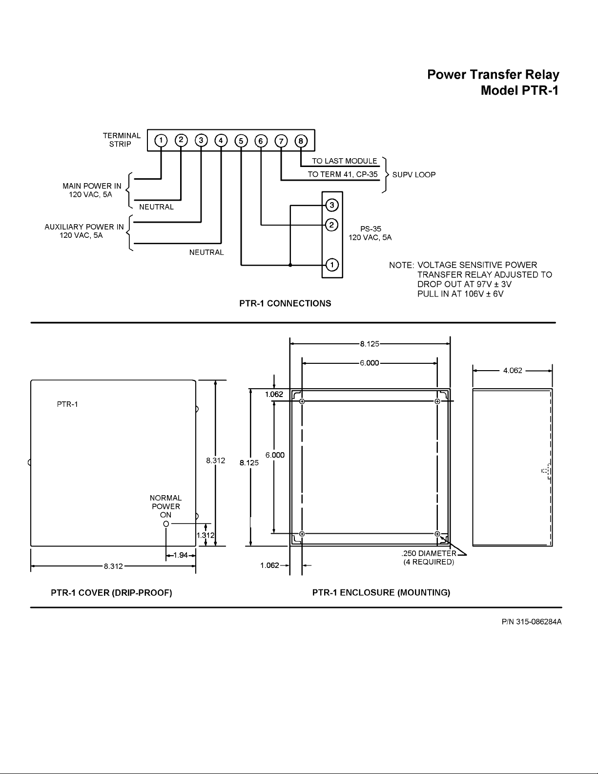
39
Page 45
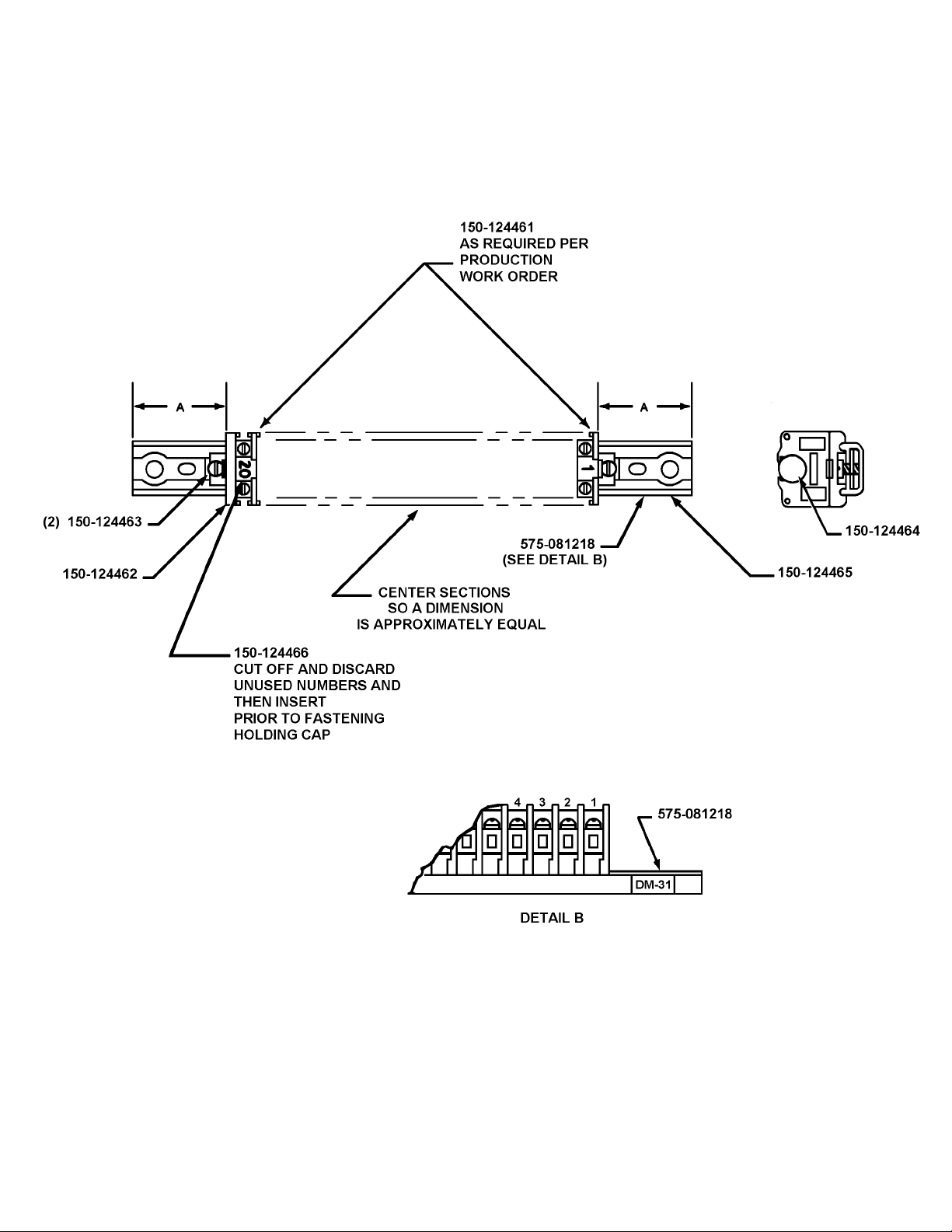
40
P/N 515-021941
Page 46

Siemens Industry, Inc.
Building Technologies Division
8 Fernwood Road
Florham Park, NJ 07932
P/N 315-086283-9
Document ID A6V10283756
Phone (973) 593-2600
Fax (973) 593-6612
www.sbt.siemens.com/fis
 Loading...