

Page 1
s
E
FireSafety&SecurityProducts
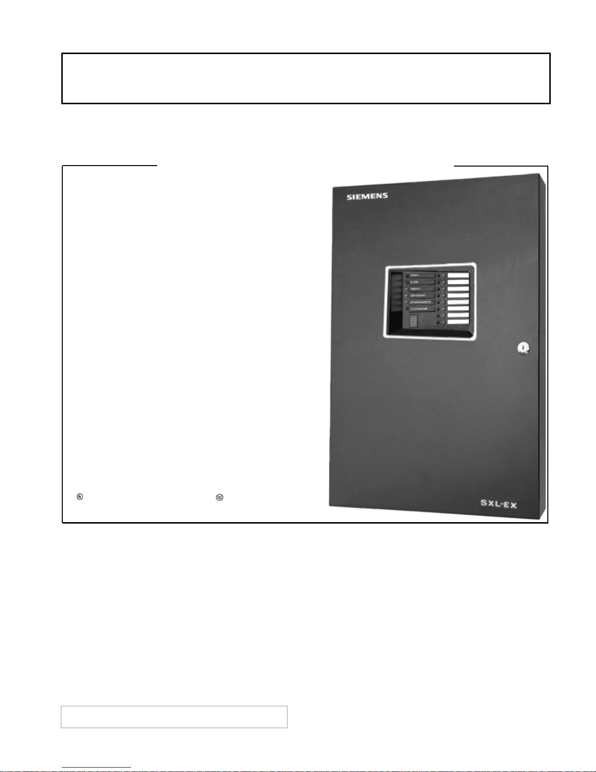
SXL-EX Fire Control Panel
DataSheet
Conventional Zone Fire Alarm Control Panel
• Four (4) zones ─ expandable to eight (8) zones
• Series 3 and 11 compatible detectors and
accessories
• Microprocessor-based control
• Factory programmed
• Two (2) Style Y notification appliance circuits
(NACs)
• 3 Amps notification and auxiliary power
• 24 and 60-hour battery backup
• Eight (8) ‘Form C’ relay-output option
• 220/240 VAC, 50 Hz power-supply option
• Remote serial-annunciator option
• Sprinkler supervisory service
• Non-silenceable bell service
• Alarm verification by zone
• One-person test feature
• Zone / output bypass feature
• Subsequent Alarm and Trouble commands with
24-hour reminders
• Alarm, Trouble and Supervisory last-event records
• UL 864 9th Edition Listed & ULC Listed;
CSFM Approved
ARCHITECT AND ENGINEER SPECIFICATIONS
─ field configurable
System Overview
Model SXL-EX from Siemens ─ Fire Safety is a
microprocessor-based fire-alarm control panel (FACP)
supplied with four (4) conventional zones, and is
expandable to eight (8) conventional zones. Model
SXL-EX also contains features, such as: field
programmability; power-limited circuits, one-person
person test; remote annunciation, and sufficient
power to meet ADA requirements for signaling.
Model SXL-EX is designed to meet the varied firealarm needs for small office buildings, apartment
buildings, department stores, hotels, strip malls or
anywhere a cost-efficient, general-purpose FACP is
required.
* AsterisksshowninthesecondcolumndenoteModelsDI‐3C;
‐11CandPE‐11TC,respectively,inCanada
P
s Industry, Inc.
Building Technologies Division
Additionally, the SXL-EX can be used to supply remote
bell power for larger systems such as the MXL FACP.
Initiating Circuits
Model SXL-EX has four (4) conventional, Style B (Class
B) zones, which are typically compatible with the
ionization detector (Model DI-3*); the photoelectric
detector (Model PE-11*) and the photo-thermal
detector (Model PE-11T*); Siemens Fire Safety thermal,
flame and beam detectors, and the MS Series of
manual stations. (Please refer to the detectorcompatibility list in the wiring diagram for specific
compatibility questions).
SXL-EX
7906
Page 2

System Overview – (continued)
Any combination of 30 compatible smoke detectors can
be combined on a given zone. Any number of thermal
detectors, manual stations or other compatible direct
shorting devices may be connected to each zone. All of
these initiating devices can be mixed on the same zone,
providing the total power requirement of the zone does
not exceed 9mA supervisory current. Model SXL-EX has
the additional capacity to support detector accessories
such as: relays, remote alarm lamps and audible bases.
Initiating zones can be programmed for many
functions. Alarm verification allows detector
application in sensitive areas
manual stations
code. Manual station operation shall not be delayed
on verified zones. Generic zone function allows the
NACs in Model SXL-EX to follow the action of a
master fire-alarm panel in the facility.
Initiating zones can also be bypassed as required for
example during construction on the premises. The system
is expanded through the (4) four-zone expander (Model
SZE-4X), which has an additional four (4) initiating
circuits, in addition to relays and open-collector outputs.
─ mixed on the zone, as allowed by
Notification Appliance Circuits
Model SXL-EX has two (2) Style Y (Class B) NACs, each
rated at 1.5 Amps. The total power output of the panel,
between the two (2) notification circuits and the auxiliary
output, is limited to 3 Amps, which is sufficient to provide
power for many applications requiring appliances
designed to ADA specifications. The SXL-EX notification
circuits are power limited to reduce installation costs
without the addition of any hardware.
NACs can be programmed for various codes. These include:
temporal / march time, simplified zone code, and number of
rounds. They can also be inhibited during test and
programming functions.
The two (2) circuits can be individually programmed as
non-silenceable. This steady operation can be used for
strobes that must continue operation after audible
devices are silenced.
Relays and Outputs
Model SXL-EX has ‘Form C’ relays for general alarm and
trouble commands, rated at 1 Amp, 30VDC. The
optional (4) four-zone expander module (Model SZE-4X)
has an additional four (4) general purpose,
programmable relays at 2 Amps, 30VDC / 120VAC. All
remote operations in the fire-alarm system are
controlled from Model SZE-4X or the relay module
(SRC-8)
Model SXL-EX enclosure.
─ each of which is situated within the actual
Visual and Audible Indicators
Model SXL-EX has visible LED annunciation by zone for
alarm and trouble prompts.
s Industry, Inc.
Building Technologies Division
─ with or without
Additionally, there is a system alarm light-emitting diode
(LED) and a system trouble LED. Supervisory zones utilize
the zone trouble LED flashing in sync with a system
supervisory LED to indicate an abnormal system event.
LEDs for AC power bypass and test / program mode are
clustered with the system alarm, trouble and supervisory
LEDs. A (7) seven-segment display
and programming functions
system trouble event. Trouble conditions are also
annunciated by a piezo-electric sounder housed inside
Model SXL-EX.
Remote annunciation is accomplished through a serial
connection with Model LED-3 or Model LED-4, (8) eightzone LED annunciators. Models LED-3 and LED-4 display
alarm, supervisory and trouble conditions for eight (8)
zones. A total of two (2) modules can be attached to
each system. Model LED-3 comes with a black
enclosure, while Model LED-4 uses a white enclosure.
─ used during testing
─ reports a code for each
Auxiliary Power
Model SXL-EX contains a 1/2 Amp auxiliary power circuit
that is used to drive remote devices. The total power for
Model SXL-EX, between the auxiliary output and the two (2)
NACs, is 3 Amps.
Power Supply / Battery Charger
The power supply accepts a 120VAC, 60 Hz. Input or,
optionally, a 220 / 240VAC, 50 Hz. Input. On loss of AC
power, the system switches to battery operation, indicating
a loss of power by flashing the AC power LED on the display.
Battery capacities of 24 and 60 hours are available.
Manual Controls
Model SXL-EX has four (4) switches for acknowledging
alarm, supervisory and trouble conditions; silencing NACs;
resetting the system, and for the drill function. These
switches are also used when programming the control unit.
Field Programmability and Test Functions
The following functions of Model SXL-EX are field
programmable, and are generally not programmed in the
unit, since the each unit is shipped ‘as received’ from the
factory. Field programming is accomplished through the
display, and does not require the use of a computer or any
proprietary tools.
Initiating Circuits:
─ Alarm Verification by Zone; Zone Bypass; Supervisory Zone,
or Generic Zone [when Model SXL-EX is used to provide
remote NACs]
Note: The default mode is an alarm-causing zone.
Notification Appliance Circuits:
─ Non-silenceable, Simple Zone Coding, March Time,
Temporal, Silence Inhibit, Cutoff Timers and Reminders
Note: The default mode is a steady signal.
Page 3

System Overview – (continued)
Details for Ordering
Outputs:
─ Bypass Outputs / Relays
System Programming:
─ Zone to Output Matrix and Password Maintenance
System-test features include: one-person test feature,
a lamp test, search and clear of the alarm, trouble and
supervisory history buffer.
Specifications
The fire-alarm control panel (FACP) shall be a Siemens
Fire Safety SXL-EX; shall utilize conventional zones and
shall be microprocessor based and fully field
programmable. The base panel shall include four (4)
initiating zones, relays for general alarm and trouble and
two (2) power-limited notification circuits capable of a
total of 3 Amps of power.
The system shall be expandable via an expander
module (model SZE-4X), which contains an additional
four (4) conventional zones; four (4) general-purpose
relays and four (4) general-purpose, open-collector
outputs.
The fire-alarm system shall have the following
features: subsequent alarm and trouble prompts; one
person test feature; brown out protection, and 24 or
60 hour battery backup. Model SXL-EX also has the
following selectable features: supervisory zones;
alarm verification by zone; non-latching zones; alarm,
trouble and supervisory history, NAC coding, alarm /
trouble 24-hour reminder, and zone / output bypass.
Any initiating-device circuit shall have the capability of
being mapped to any optional output, via the systemprogramming function.
The FACP shall be
requirements of NFPA 72 for local fire alarm control
for automatic or manual service, and for sprinkler
supervisory and waterflow service.
Model SLX-EX shall meet NFPA 72 requirements for
central-station service when connected to Model 5128
or Model 5129 digital fire communicator.
The system can alternately be expanded through
the expander module (Model SZE-8AX), which has
an additional four (4) Class A (Style D) initiating
circuits. Model SZE-8AX also converts the four (4)
initiating circuits and the two (2) notification
circuits on the main SXL-EX to Style D (Class A) and
Style Z (Class A), respectively.
UL / ULC Listed, and meet the
Model
Number
(Black Enclosure)
SXL-EX-RED Planning Bill
(Red Enclosure)
SXL-EX-DF Planning Bill
(Dead Front,
Black Enclosure)
(International,
Black Enclosure)
Part
Number
500-695884 EN-SX Enclosure SXL-EX Planning Bill
500-696000 SXL-XLCON
500-696011 EN-SX Enclosure (Red)
600-696000 SXL-XLCON
500-695885 EN-SX Enclosure
500-696000 SXL-XLCON
500-695889 DF-SX Dead Front
500-695885 EN-SX Enclosure SXL-EX-INT
500-696010
Description
SXL-EX-INT Board,
Transformer & Hardware
SXL Optional Modules
Model
Number
SZE-4X 500-696006 SXL 4-Zone Expander (with outputs)
SZE-8AX 500-696007 SXL 8-Class “A” Zone Module
SRC-8 500-692972 SXL 8-Relay Module
RPR-1 500-694998 Remote Polarized 24VDC Relay
SLT-1 500-093285 SXL Leased Line / Municipal Tie Module
MM-SX 500-696008 Meter Module for SXL-EX
LED-3 500-693062 LED-3 Annunciator
Part
Number
Description
(with SXL, MXL and System 3 FACPs)
SXL Control Equipment Components
SXL-XCON 500-696000 SXL-EX Board, Transformer & Hardware
SXL-XCON-INT
EN-SX 500-695884 SXL-EX Enclosure, Black
EN-SXR 500-696011 SXL-EX Enclosure, Red
DF-SX 500-695889 SXL-EX Dead Front Kit. Black Only
FT-SX 500-695890 SXL-EX Semi-Flush Trim Kit
FT-SXR 500-696104 SXL-EX Semi-Flush Trim, Red
SXL-AK 500-696358 SXL-EX / ENS-S Adapter Kit
SXL-MAIN 500-695992 SXL-X Main PCB Assembly Pkg.
500-696010
SXL-EX-INT Board, Transformer & Hardware
SXL Batteries & Power Supplies
BT-33 175-387141 6AH Battery Set
BT-34 175-387140 10AH Battery Set
BP-61 175-387194 15AH Battery Set
PAD-3 599-699189 P/S NAC EXT (6 Amps)
PAD-3R 599-699190 P/S NAC EXT, Red
PAD-3-MB 500-699080 Main Board Only for PAD-3
EN-PAD 310-099073 Black Enclosure for PAD-3
EN-PADR 310-099150 Red Enclosure for PAD-3
PAD-3-UK 500-648449 PAD-3-UK Upgrade Kit
SXL Upgrade Kits
SXL-EX-UK 500-363009 SXL-EX-UK F/W Upgrade Kit
SLT-1-UK 500-699052 SLT-1F/W Upgrade Kit
LED-UK 500-696205 LED-3/4 Upgrade Kit
Digital Fire Communicators
5128C 500-693213 4-Channel Slave Communicator
5129 500-693214 4-Channel Communicator [in enclosure]
5230K 500-693215 Programmer / Annunciator [5128 / 5129]
TIK-5128 500-693218 (1) Dual-Pack-RJ331X Block & Cord
Note: Model BP-61 requires a separate enclosure (i.e. − BB-55)
s Industry, Inc.
Building Technologies Division
Page 4
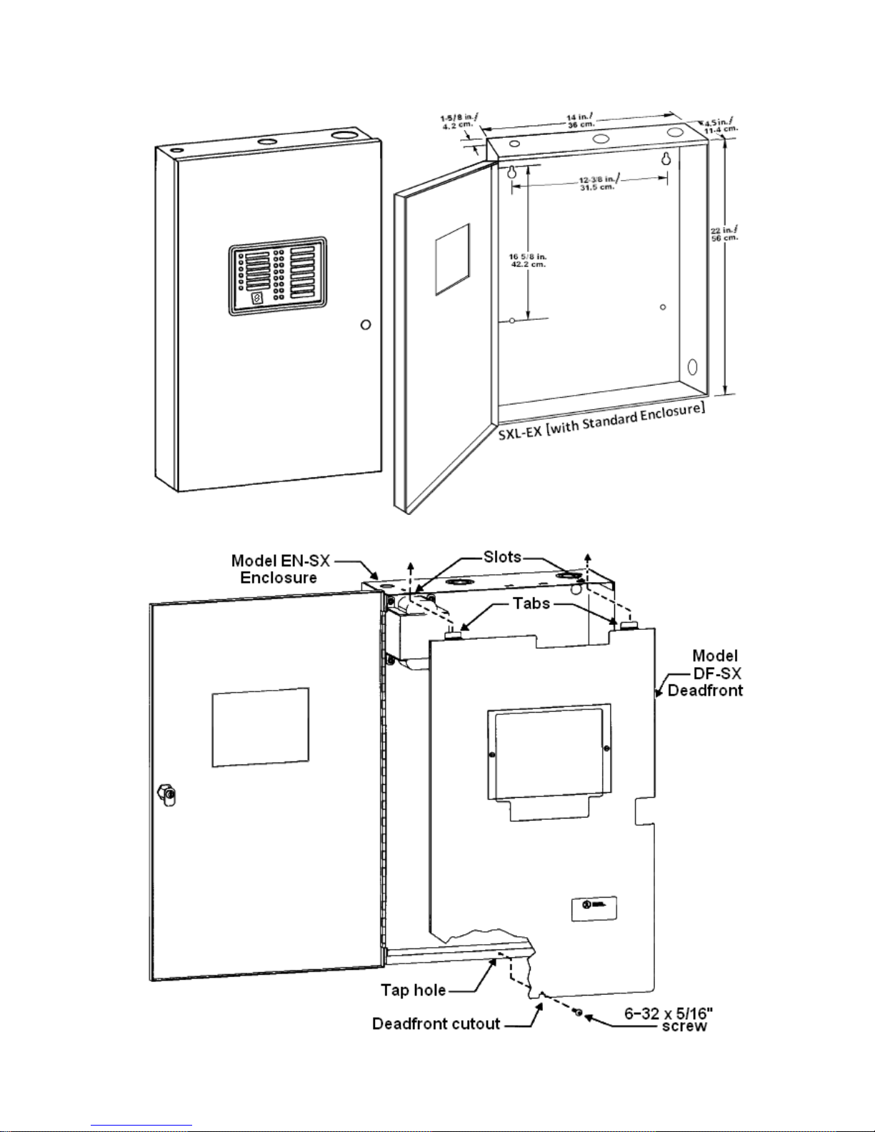
Dimensional Data
s Industry, Inc.
Building Technologies Division
SXL‐EX[withDeadfrontEnclosure]
Page 5
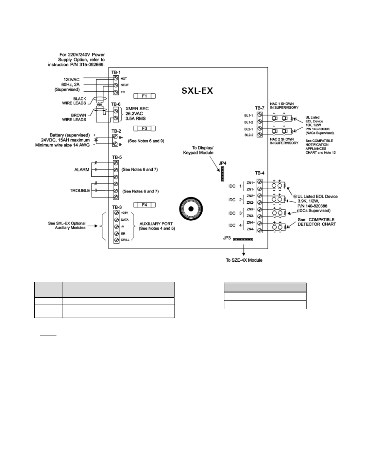
SXL-EX Main Board Connection Diagram
Fuse Replacement Electrical Ratings
Model
Number
F1 105-217858 AC Input, 8 Amps
F2 105-224090 Batteries, 15 Amps
F3 105-280300 AUX Port, 0.75 Amps
Notes:
7. All field wiring must be in accordance with NFPA 70,
Article 760.
8. Make no wiring connections while the system is powered.
9. Alarm Relay contacts are shown de-energized, and
Trouble Relay contacts are shown energized. Suitable for
resistive load only.
10. Auxiliary output rate 0.5 Amps @ +24VDC, filtered.
Maximum line impedance of 5 ohms.
11. Combined current output for NAC1, NAC2 and auxiliary
outputs is limited to 3.0 Amps.
12. Equipment connected to these terminals must be located
within the same room.
13. Refer to the SXL-EX Operation, Installation and
Maintenance Manual (IOM): P/N 315-095997, for further
.
details
Part
Number
Description
Alarm / Trouble Relay
244 mmHg., 41 kPa @ 20°C
11.6 (ref std.: Air = 1)
1. No T-tapping allowed.
2. Connect standby batteries only to Terminals B+ and B-.
The batteries may be installed in either the bottom of the
cabinet, or in a UL Listed battery enclosure.
3. In all cases, the Siemens Fire Safety model number is the
compatibility identifier, including the control panel,
module(s), and all compatible initiating devices.
4. When using the SLT-1 module, not suitable for remote
station protected premises service where separate
transmission circuits are required for alarm, trouble and
supervisory signals.
5. All power-limited wiring requires separation from nonpower-limited wiring. Refer to the SXL-EX Power Limited
Wiring Instructions: P/N 315-095994.
s Industry, Inc.
Building Technologies Division
Page 6
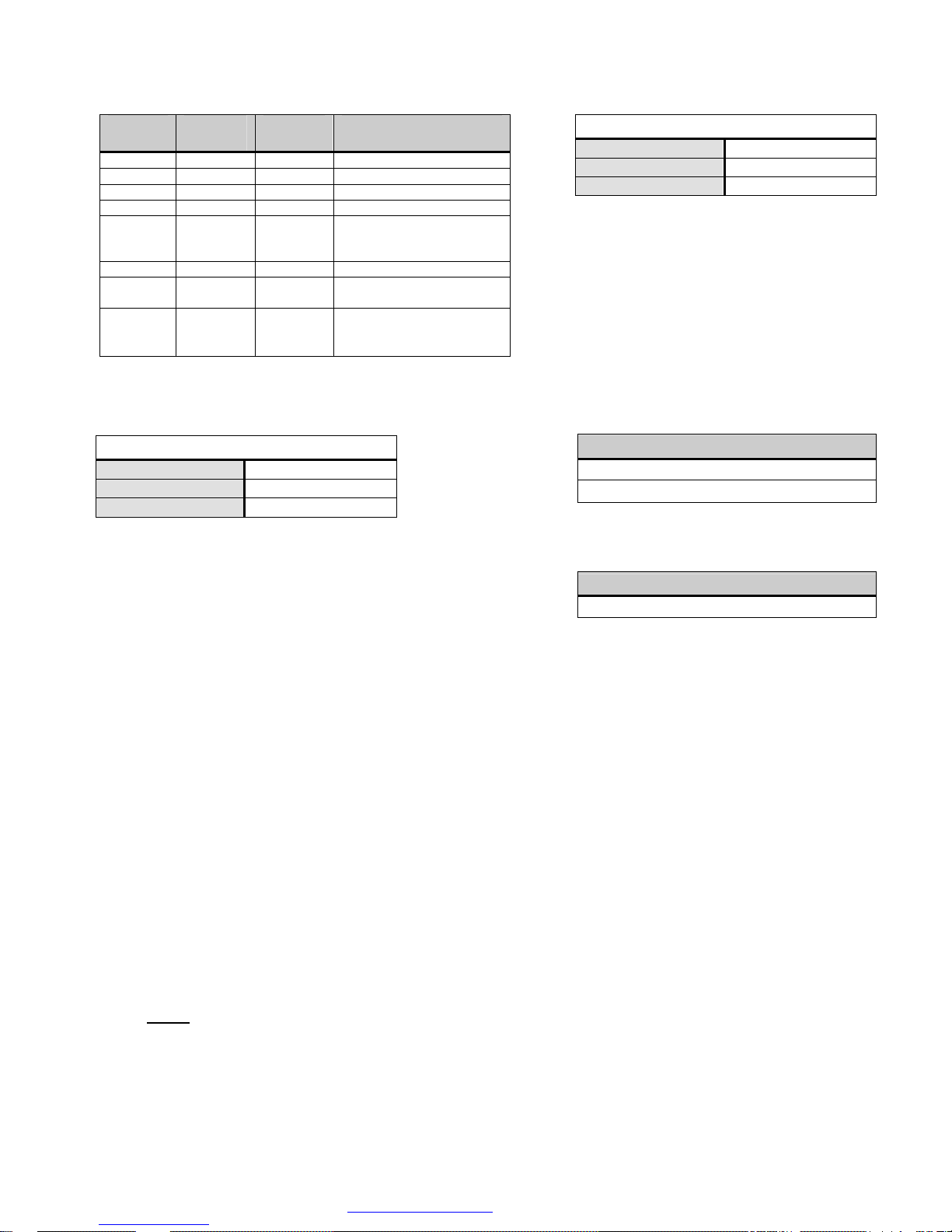
Compatibility Detectors Electrical Ratings
Detector
DI-3 / 3H 30 DB-3S 315-081943
DI-A3 / A3H 30 DB-3S 315-081943
DI-B3 / B3H 30 AD-31 315-093234
DT-3P-135 30 DB-3S 315-084401
DT-11 30
PB-119A 1 PB-1191B 315-095424
PE-3 / 3T
PE-11 / 11T
Quantity
per Loop
30
30
Base
DB-11
DB-3S with
DB-ADPT
DB-3S
AD-3ILP
DB-11
DB-3S with
DB-ADPT
Installation Instructions
Part Number
315-095429
315-095429
315-090875
315-093234
315-094198
315-094198
Initiating Device Circuit
Voltage:
Supervisory Current:
Alarm Current:
Maximum line impedance of 25 ohms per IDC zone
All IDC zones are supervised and power limited, per
NFPA 70, Article 760
Each IDC zone must use at least 18 AWG, 300V
insulation, color-coded wire for low-voltage circuits
where local codes require conduit. Where local
codes permit, use limited-energy shielded cable
rated at 300V.
Each IDC zone will support one (1) initiating device
in alarm mode. The IDC zone compatibility is an
unlimited number of shorting-type devices.
For smoke-detector compatibility, see: Compatible
Detectors’ chart.
16.4 − 26.4VDC
9mA, max.
120mA, max.
Electrical Ratings
Notification Appliance Circuits (NACs)
Voltage:
Supervisory Current:
Alarm Current:
Each NAC is rated at 1.5 Amps, +24VDC.
Maximum line impedance, 3.0 ohms per circuit
All NACs are supervised.
Each NAC must use at least 14 AWG, 300V
insulation, color-coded wire.
All NACs are power limited per NFPA 70, Article
-
24VDC
1.5mA, max.
1.5A, max.
Model SZE-4X ‘Form C’ Relay
2.0 Amps @ 30 VDC, Resistive Only
0.5 Amps @ 30 VAC, Resistive Only
Open Collector
50mA, max. @ 26.4 VDC, max.
Notice: This marketing data sheet is not intended to be used for system design or installation purposes.
For the most up-to-date information, refer to each product’s installation instructions.
s Industry, Inc.
Building Technologies Division
Fire Safety
8 Fernwood Road
Florham Park, NJ 07932
Tel: (973) 593-2600
FAX: (908) 547-6877
URL: www.SBT.Siemens.com/FIS
(SII‐FS)
Printed in U.S.A.
Fire Safety
2 Kenview Boulevard
Brampton, Ontario
L6T 5E4 / Canada
Tel: (905) 799-9937
FAX: (905) 799-9858
October 2010
Supersedes sheet dated 5/02
(Rev. 1)
 Loading...