

Page 1
CA1N4895en
08.03.2004
Siemens Building Technologies
HVAC Products
4
895
Electrical Actuators
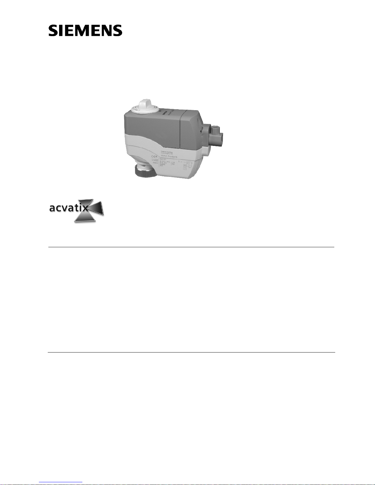
for valves VVP45..., VXP45..., VMP45...
SSC31
SSC81
SSC61...
• SSC31 operating voltage AC 230 V 3-position control signal
• SSC81 operating voltage AC 24 V 3-position control signal
• SSC61 operating voltage AC/DC 24 V DC 0…10 V control signal
• SSC61.5 same as SSC61, plus electrical fail-safe function
• Nominal force 300 N
• Automatic identification of valve stroke
• Direct mounting with coupling nut, no tools required
• Cable connection via screw terminals
• Manual override, indication of position and direction of travel
• Parallel connection of multiple actuators
• Special UL-listed versions
Use
For operation of Siemens valves of the VVP45..., VXP45... and VMP45... range for
water-side control of hot water and cooling water in heating, ventilation and air
conditioning systems
.
In conjunction with the ASK30 mounting kit, the former Landis & Gyr valves VVG45...,
VXG45... and X3i... can also be operated.
Page 2
2/8
Siemens Building Technologies Electrical Actuators CA1N4895en
HVAC Products 08.03.2004
Type summary
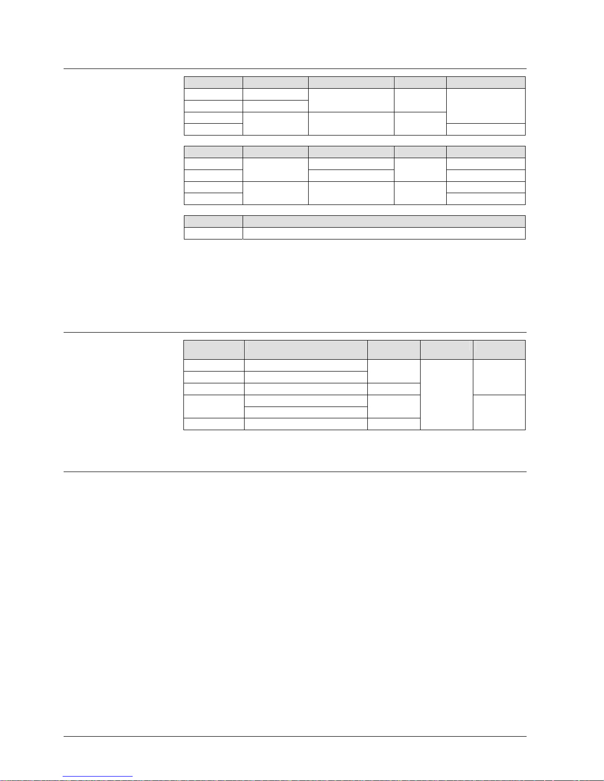
Type reference Rated voltage Running time at 50 Hz Control signal Remarks
SSC31 AC 230 V 150 s 3-position
SSC81 AC 24 V
SSC61 AC/DC 24 V 30 s DC 0...10 V
SSC61.5 With fail-safe function
Type reference Rated voltage Running time at 50 Hz Control signal Remarks
SSC81U AC 24 V 150 s 3-position
SSC81.5U 125 s With fail-safe function
SSC61U AC/DC 24 V 30 s DC 0...10 V
SSC61.5U With fail-safe function
Type reference Description
ASK30 Mounting kit for use with former Landis & Gyr valves VVG45…, VXG45… and X3i...
When ordering, please give quantity, product name and type reference.
2 actuators SSC81
The actuators, valves and accessories are packed separately.
Equipment combinations
Type reference Type of valve
kvs
[m3/h]
PN class
Data Sheet
VVP45... 2-port valves 0.25...25 PN16 N4845
VXP45... 3-port valves
VMP45... 3-port valves with T-bypass 0.25...4
VVG45...1) 2-port valves 0.63...25
VXG45...1) 3-port valves
X3i...1) 3-port valves 0.7...14
Retrofitting to
former L&G
valves
1)
With ASK30 mounting kit
Function / mechanical design
When the actuator is driven by a 3-position or DC 0…10 V control signal, it generates a
stroke which is transmitted to the valve stem.
• Voltage at Y1: Actuator stem extends and valve opens
• Voltage at Y2: Actuator stem retracts and valve closes
• No voltage at Y1 or Y2: Actuator maintains the current position
• The valve opens / closes in proportion to the control signal at Y
• At DC 0 V, the valve is fully closed (A → AB)
• In the event of a power failure, the actuator maintains its current position
Standard versions
Special UL-listed
versions
Accessories
Ordering
Example
:
Delivery
3-position actuators
SSC31 / SSC81
DC 0...10 V control
SSC61
Page 3
3/8
Siemens Building Technologies Electrical Actuators CA1N4895en
HVAC Products 08.03.2004
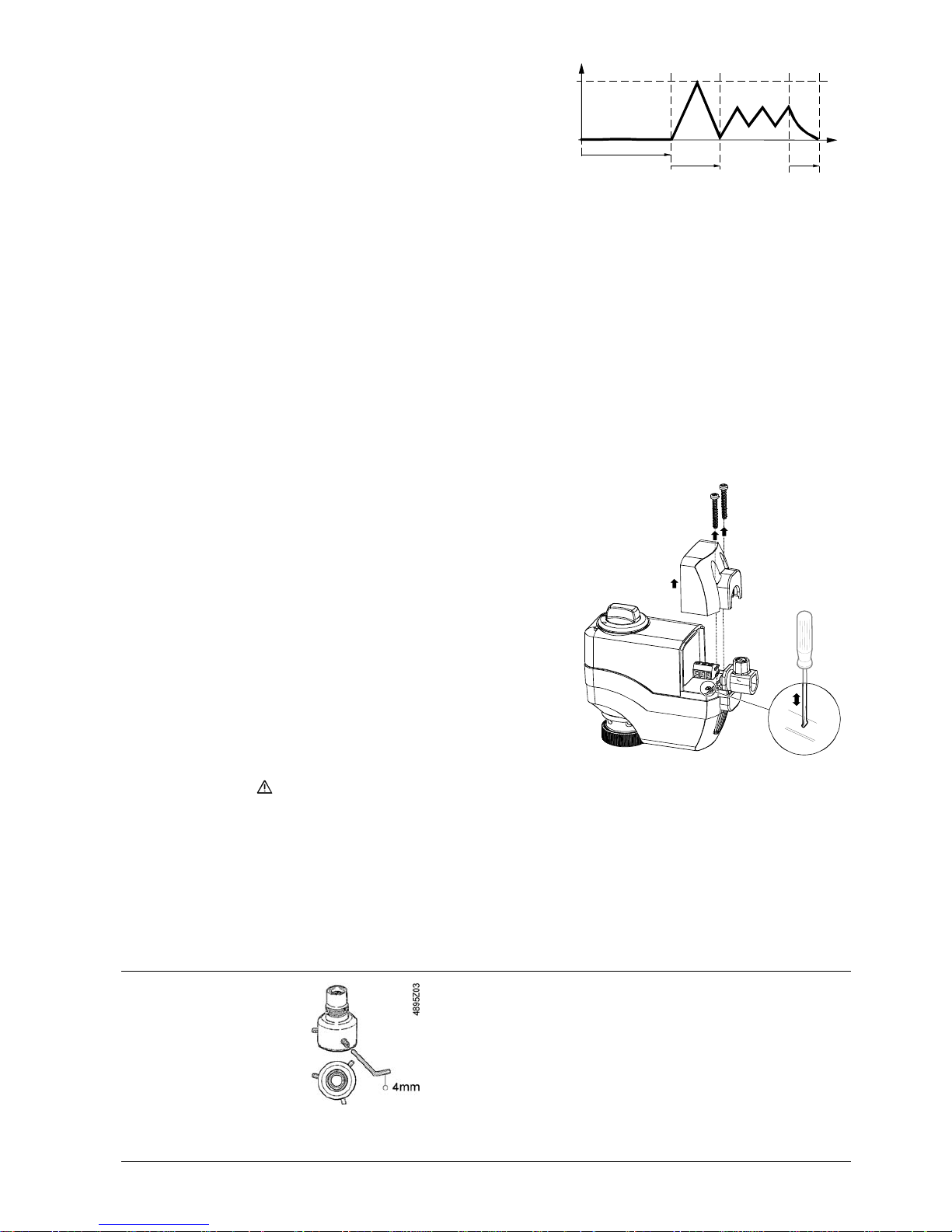
When first connected to power, or
after a power failure, the capacitor
which stores energy for the fail-safe
function will be charged. This process
takes up to 180 seconds. While the
capacitor is being charged, the
actuator cannot respond to any Y
control signals.
max 180 s
max
30 s
Charging
Calibration Discharge
4895Z01en
Stroke [%
]
100
0
t
60 s
Normal
actuator
operation
On completion of the charging process and auto calibration (see below), the "Open"
and "Close" travel are proportional to the DC 0…10 V control signal.
In the event of a power failure of more than 5 seconds, the actuator will return
mechanically to its 0 % stroke position within 30 seconds, closing the valve
(A → AB).
When the AC / DC 24 V supply is applied for the first time, the actuators calibrate
themselves independent of the control signal. In this process, the actuator drives the
valve to the mechanical end stops and stores the associated positions permanently in the
form of electronic values. The positioning signal is only active on completion of this
calibration process. Calibration takes about 60 seconds.
The SSC61.5 only performs auto calibration when the charging process of 180 seconds
is completed.
If the calibrated actuator is used with
some other valve (e.g. a replacement
valve), it must be recalibrated. For that
purpose, the PCB beneath the terminal
cover has a slot (see illustration). To
make the recalibration, use a
screwdriver and connect the 2 contacts
behind the slot for about 1 second.
3
2
1
4895Z02
The calibration can only be made correctly if the actuator is fitted to a valve (refer to
«Equipment combinations»).
• Plastic cover
• Locking-proof, maintenance-free gear train
• Manual adjustment with rotary knob
• Reduced power consumption in the holding positions
• Load-dependent switch-off in the event of overload and in stroke limit positions
Accessories
Type ASK30
Electrical fail-safe
function
SSC61.5
Auto calibration
SSC61 and SSC61.5
Recalibration
Features and benefits
Mounting kit
Page 4
4/8
Siemens Building Technologies Electrical Actuators CA1N4895en
HVAC Products 08.03.2004
Notes
The actuators must be electrically connected in accordance with local regulations (refer
to «Connection diagrams»).
Regulations and requirements to ensure the safety of people and property must
be observed at all times!
The permissible temperatures must be observed (refer to «Technical data»).
Mounting Instructions 74 319 0260 0 are enclosed with each pack.
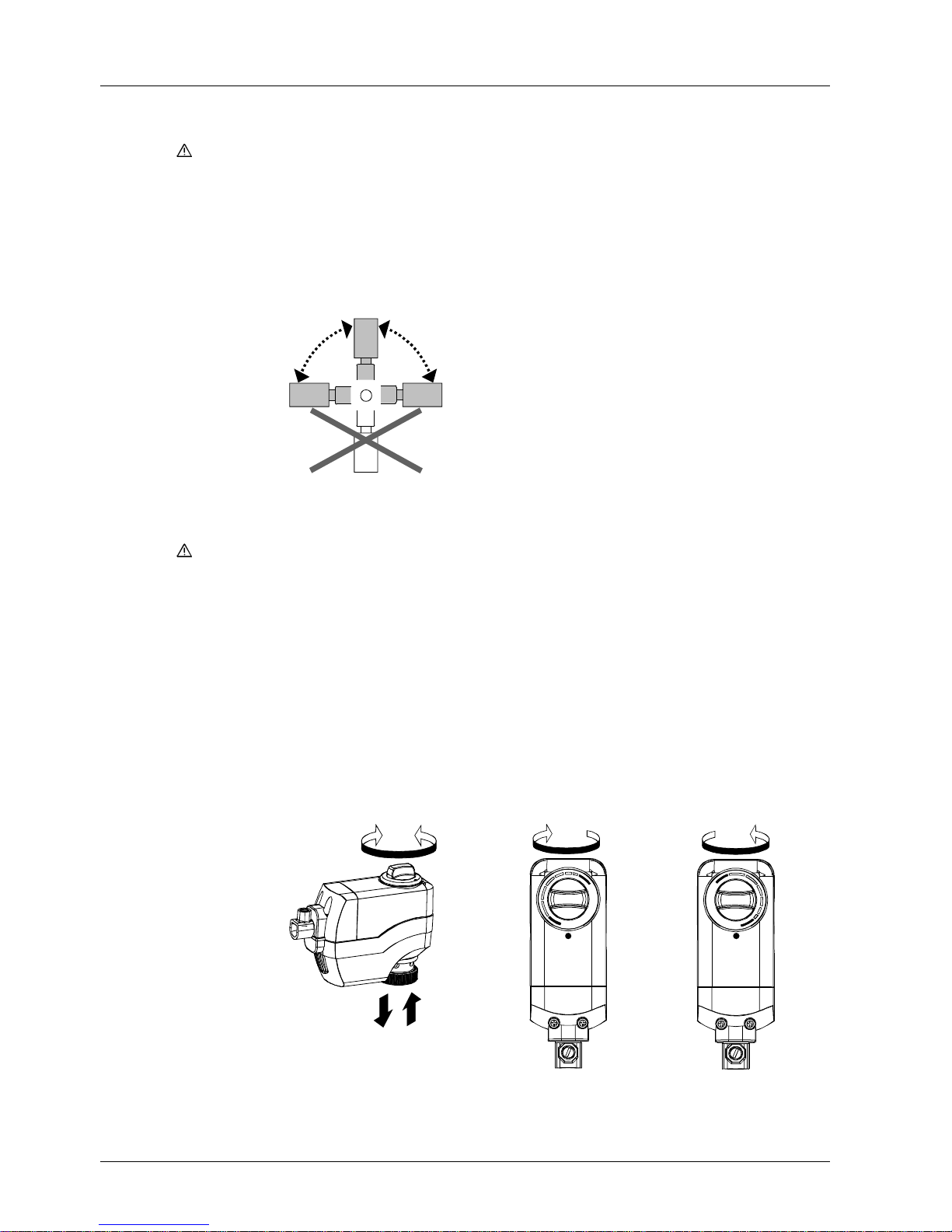
Assembly is made with the coupling nut; no tools or adjustments are required. The
actuators should be installed so that they are initially in position 0 (also refer to
«Operation»).
90° 90°
4899Z03
When commissioning the system, check wiring and the functions of the actuator.
Before testing the functioning of the SSC..., always check to ensure that the
actuator concerned is mounted on a valve (refer to «Equipment combinations»).
Calibrating the SSC61 or SSC61.5 without a valve connected causes the actuator to
lock in position 1. To recalibrate (after mounting on a valve), disconnect power and
reset the stroke manually from position 1 to 0 (refer to «Recalibration»).
The rotary knob can be used to drive the actuator into any position between 0 and 1.
However, if a control signal from the controller is present, this will take priority in
determining the position.
To retain the manually set position, unplug the connecting cable. Due to the reset
function, the SSC61.5 will first travel to position 0 and can then be driven manually to the
required position.
BA
B
(Y2)(Y, Y1)
A
4895Z04
A
4895Z05
0
1
Position indicator in
position 1 = OPEN
B
4895Z06
0
1
Position indicator in
position 0 = CLOSED
Engineering
Caution
Mounting
Orientation
Commissioning
Caution
Operation
Note
Page 5
5/8
Siemens Building Technologies Electrical Actuators CA1N4895en
HVAC Products 08.03.2004
When servicing the actuator:
• Switch off power
• If necessary, disconnect the terminals
• The actuator must only be commissioned with a correctly mounted valve in place!
The SSC... actuators cannot be repaired. They must be replaced as a complete unit.
Disposal
The device may not be disposed of together with domestic waste.
This applies in
particular to the PCB.
Legislation may demand special handling of certain components, or it may be sensible
from an ecological point of view.
Current local legislation must be observed.
Warranty
The technical data (∆p
max
, ∆p
s
, leakage rates, noise levels, service life, etc.) relating to
specific applications are valid only in conjunction with the Siemens valves listed in this
Data Sheet under «Equipment combinations».
The use of the SSC… actuators in conjunction with third-party valves invalidates
any warranty offered by Siemens Building Technologies / HVAC Products.
Technical data
SSC31 SSC81 SSC61 SSC61.5
AC 24 V or DC 24 V Power supply
Rated voltage
Voltage tolerance
AC 230 V
± 15 %
AC 24 V
± 20 %
± 20 % ± 25 %
Rated frequency 50 / 60 Hz
Max. power consumption 6 VA 0.8 VA 2 VA
2 VA
1)
Fuse for incoming cable (fast) 2 A
Control Control signal 3-position DC 0...10 V
Input impedance for DC 0...10 V ––– > 100 kOhm
Positioning accuracy for DC 0...10 V ––– < 2 % of nominal stroke
Parallel operation
(number of actuators)
3)
max. 10
Functional data Running time for 5.5 mm stroke 150 s ± 2 % 30 s ± 10 %
Capacitor charging time ––– max. 180 s
Fail-safe run time ––– 30 s
Nominal stroke 5.5 mm
Nominal force > 300 N
Permissible temperature of
medium in the connected valve
1...110 °C
Electrical connections
Terminal block, pluggable
screw terminals for max. 3 mm
2
Terminal block color
green grey red red
Cable strain relief
for cables 4...11 mm dia.
Industry standards Meets the requirements for CE
marking:
EMC directive
Low-voltage directive
UL approval
2)
CUL approval
2)
89/336/EEC emissions EN 50081-1
immunity EN 61000-6-2
73/23/EEC EN 60730-1
UL873-listed
certified to Canadian Standard C22.2 No. 24-93
Safety class II III
Housing protection standard IP40 to EN 60529
Maintenance
Repair
Page 6
6/8
Siemens Building Technologies Electrical Actuators CA1N4895en
HVAC Products 08.03.2004
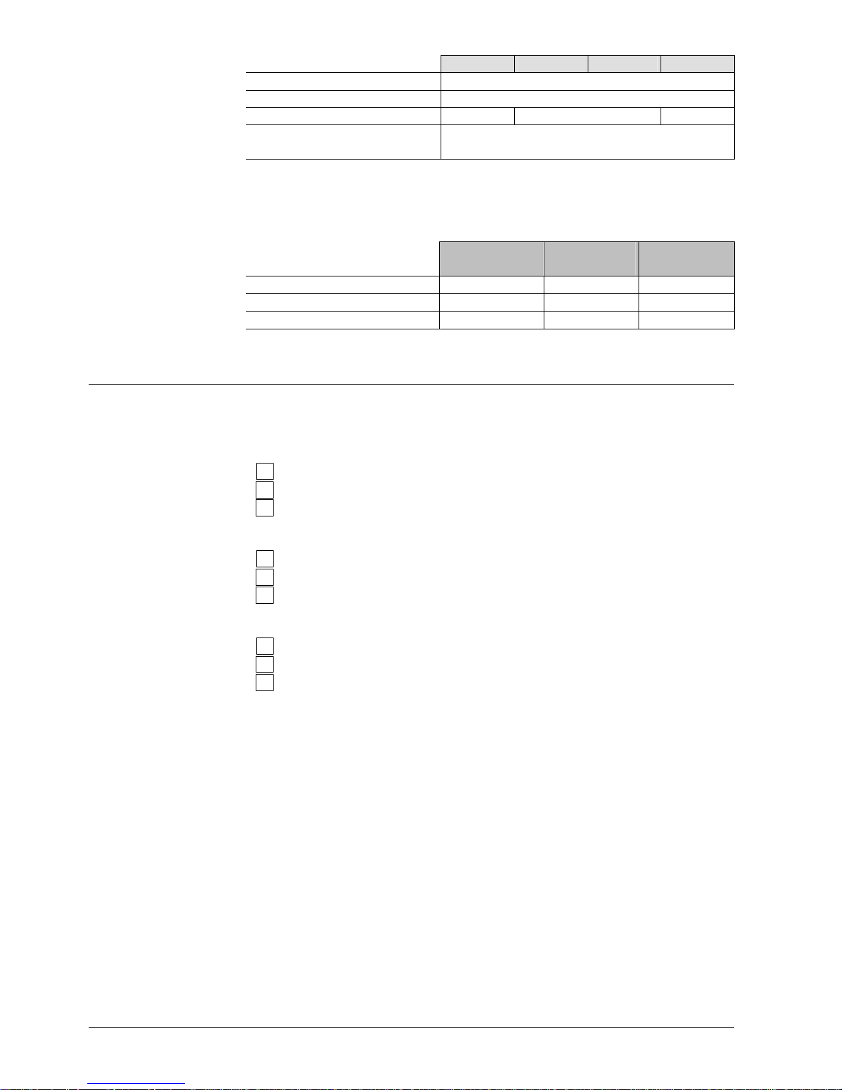
SSC31 SSC81 SSC61 SSC61.5
Dimensions / weight Dimensions refer to «Dimensions»
Coupling thread to valve coupling nut G¾
Weight 0.26 kg 0.25 kg 0.27 kg
Housing
Base, rotary knob
Cover
plastic, RAL 7035, light-grey
plastic, RAL 5014, pigeon-blue
1)
3 VA, when capacitor charged for automatic reset
2)
Applies to type SSC… actuators with type suffix U
3)
Provided the controllers’ output is sufficient
General
ambient conditions
Operation
IEC 721-3-3
Transport
IEC 721-3-2
Storage
IEC 721-3-1
Environmental conditions class 3K3 class 2K3 class 1K3
Temperature +5...+50 °C –25...+70 °C –25...+70 °C
Humidity
5...95 % r.h. < 95 % r.h. 5...95 % r.h.
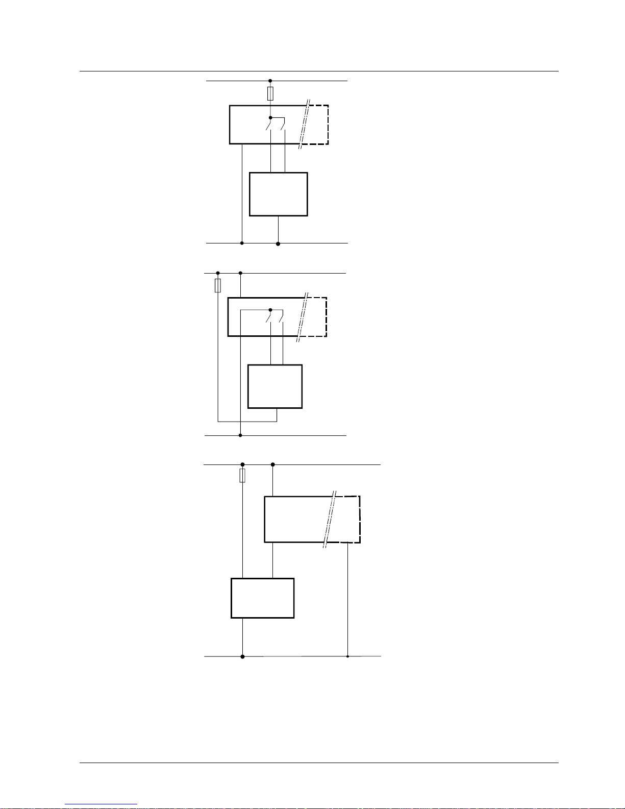
Connection terminals
All actuators must be electrically connected and installed in accordance with local
safety regulations.
Y
2
Y
1
N
4895Z06
Control signal CLOSE (AC 230 V)
Control signal OPEN (AC 230 V)
Neutral
Y
2
Y
1
G
4864Z15
Control signal CLOSE
Control signal OPEN
System potential AC 24 V
G
0
Y
G
4895Z21
Control signal DC 0...10 V
System potential AC 24 V (+ with DC 24 V)
System neutral (- with DC 24 V)
SSC31
SSC81
SSC61
SSC61.5
Page 7
7/8
Siemens Building Technologies Electrical Actuators CA1N4895en
HVAC Products 08.03.2004
Connection diagrams
N Controller
Y Actuator
L System potential AC 230 V
N System neutral
4864A01
(L)
(N)
L
N
AC 230 V
N
Y2
Y1
2AF
N
(Y1) (Y2)
Q1
Q2
Y
Q1, Q2 Controller contacts
N Controller
Y Actuator
SP System potential AC 24 V
SN System neutral
4864A02
(Y1)
(G)
(G0)
SP
SN
AC 24 V
G
Y2Y1
(Y2)
N
Q1 Q2
2AF
Y
Q1, Q2 Controller contacts
N Controller
Y Actuator
SP System potential AC 24 V
4864A03
(Y)
N
Y
(G0)
GY
G0
SP (+)
SN (-)
AC 24 V (DC 24 V)
(G)
2AF
SN System neutral
SSC31
SSC81
SSC61
SSC61.5
Page 8
8/8
Siemens Building Technologies Electrical Actuators CA1N4895en
HVAC Products 08.03.2004
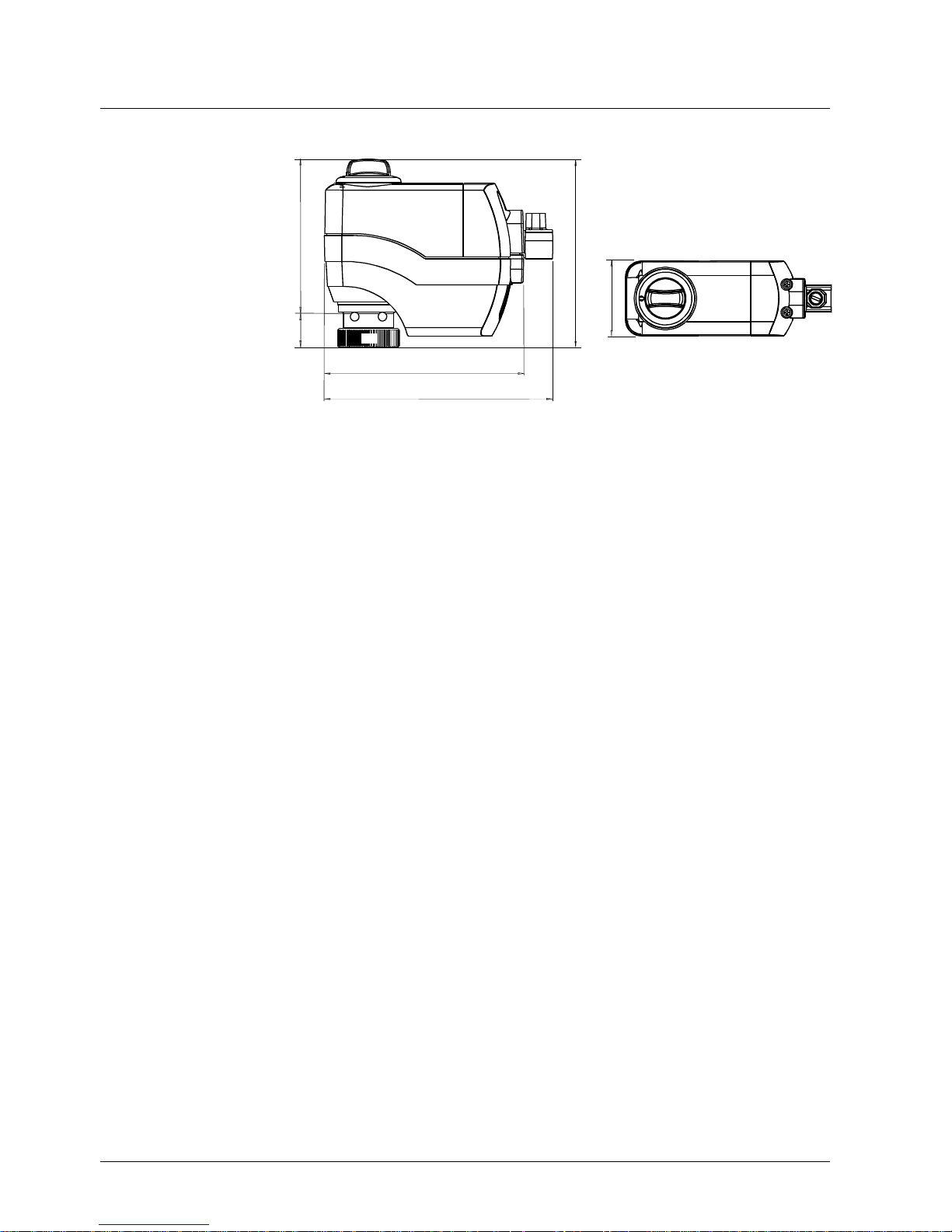
Dimensions
All dimensions in mm
48
110.8
89.2
21.6
115.1
132.5
4895Z08
G
¾
2004 Siemens Buildin
g
Technologies AG Subject to chan
ge
 Loading...