

Page 1
Powermite 599 Series
MZ Series SSB
Electronic
Valve Actuator
24 Vac Proportional Control
Technical Instructions
Document No. 155-192P25
EA 599-10
November 25, 2013
Description
Features
Application
Product Number
Ordering
Information
EA0579R2
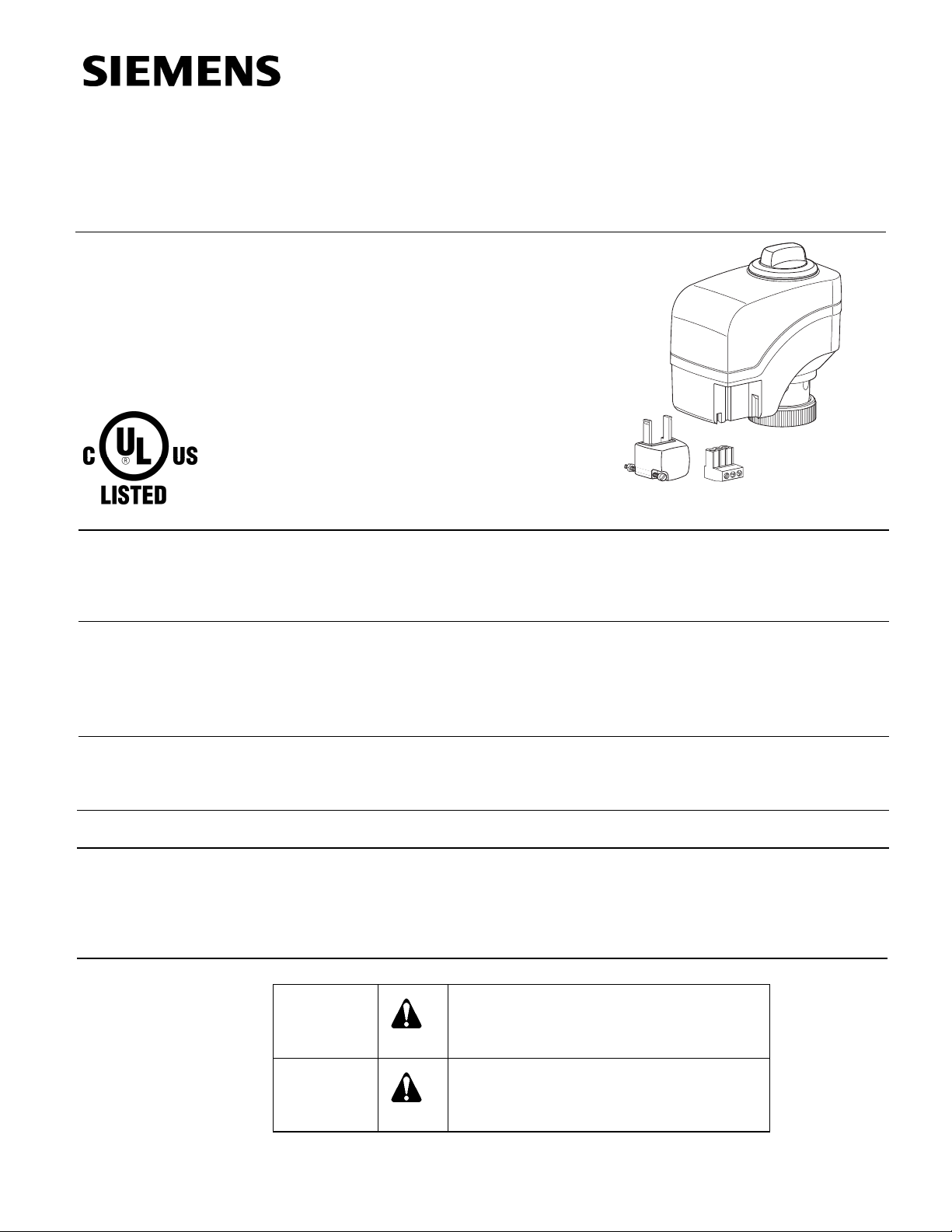
The Powermite 599 MZ Series SSB Electronic Valve Actuator requires a 24 Vac supply
and receives a 0 to 10 Vdc control signal to proportionally control a valve. This actuator
is designed to work with Powermite 599 MZ Series Zone Control Valves with a 7/32inch (5.5 mm) stroke and a threaded valve bonnet that fits the actuator.
• UL listed for plenum installations
• Direct coupled installation without tools
• Manual override
• Visual position indication
For use in heating and cooling HVAC applications with Powermite 599 MZ Series
valves that need 45 lbs. (200N) nominal force. They can be used in liquid service
applications.
SSB61U Actuator prefix code 255
To order a complete valve plus actuator assembly from the factory, combine the
actuator prefix code with the suffix of the valve product number. See Technical Bulletin
TB 252 (155-307P25) for selection procedures.
To order an actuator only, use the product number.
Warning/Caution Notations
Siemens Industry, Inc.
WARNING:
CAUTION:
Personal injury or loss of life may occur if
you do not perform a procedure as
specified.
Equipment damage or loss of data may
occur if you do not follow a procedure as
specified.
Page 2
Technical Instructions Powermite 599 MZ Series SSB Electronic Valve Actuator
Document No. 155-192P25 24 Vac Proportional Control
Noember 25, 2013
Specifications
Operating voltage 24 Vac ±20%, 24 Vdc ±25%
Frequency 50/60 Hz
Power supply
Power consumption
Vac 2.0 VA maximum
Vdc 1.8 VA maximum
Function
Nominal stroke 7/32 inches (5.5 mm)
Nominal force 45 lbs. (200N)
Running time
60 Hz 75 seconds
50 Hz 75 seconds
Agency Certification
UL Listed to UL873
cUL Certified to Canadian Standard
C22.2 No. 24-93
Ambient Conditions
Ambient temperature
Operation 34 to 122°F (1 to 50°C)
Transport and storage -13 to 158°F (-25 to 70°C)
Miscellaneous
Medium temperature 34 to 230°F (1 to 110°C)
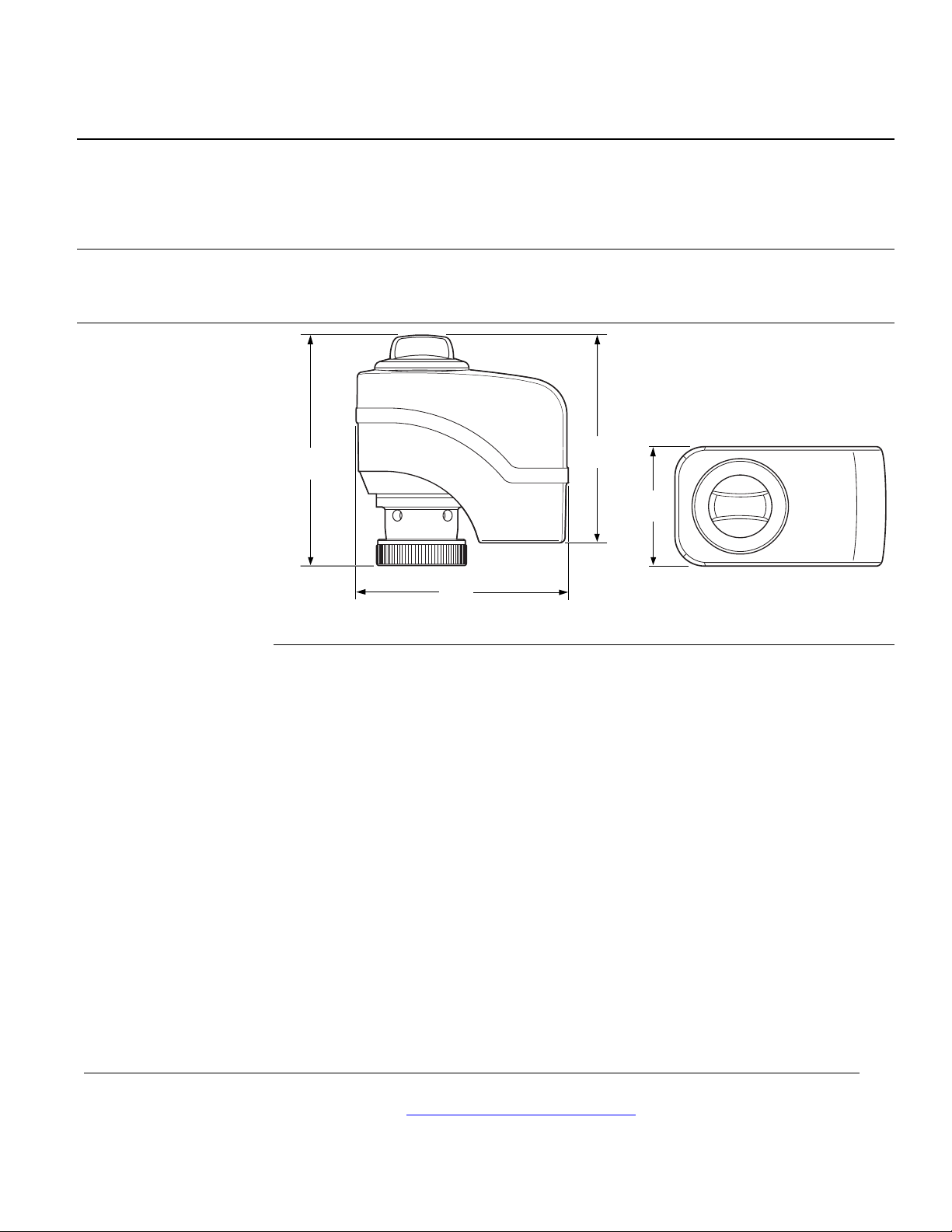
Dimensions See
Figure 7.
Weight 9 oz. (0.25 kg)
Accessory
Service Kits
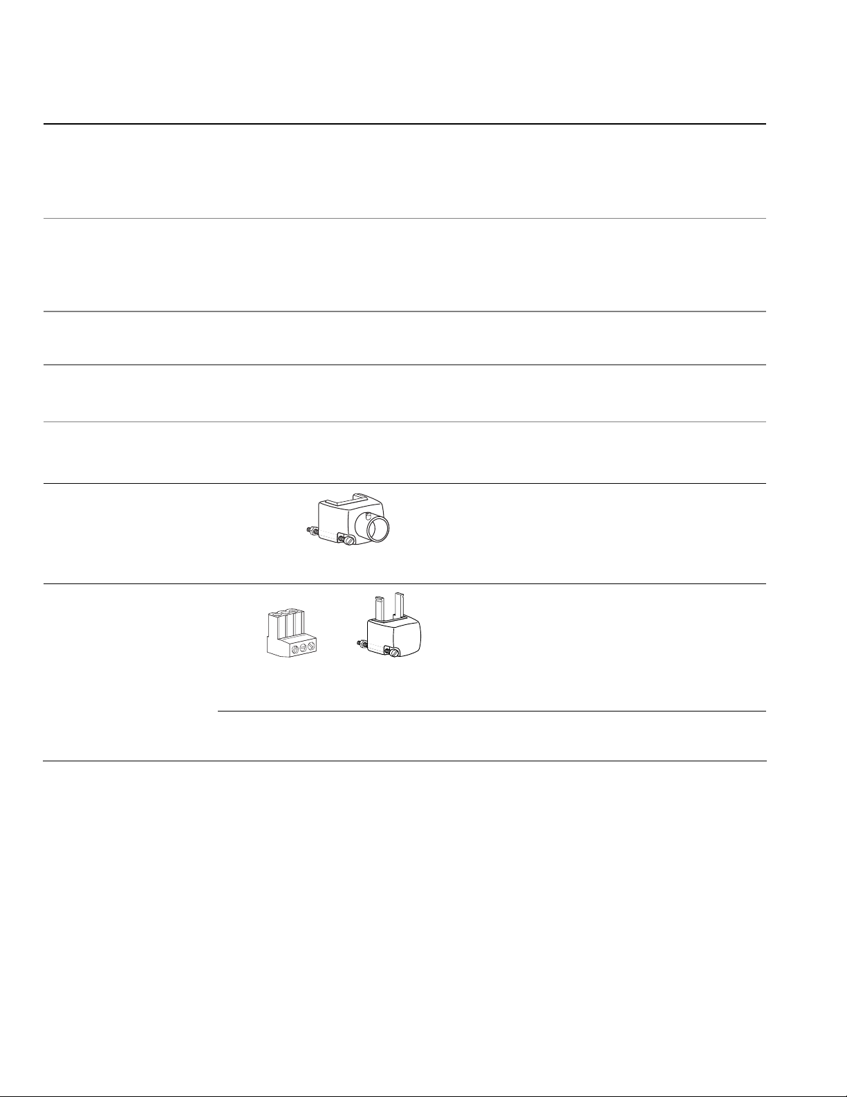
ASY97 Conduit connector (quantity one).
EA0643R1
Figure 1. Conduit Connector.
ASY100 Terminal plug and terminal block cover
for SSB61U (quantity: one each).
G Y GO
EA0582R1
EA0859R1
Figure 2. Terminal Plug and
Block Cover
ASY98 Replacement screw and nut for use on the conduit connector or the terminal
connector, quantity one each.
Page 2 Siemens Industry, Inc.
Page 3
Powermite 599 MZ Series SSB Electronic Valve Actuator Technical Instructions
24 Vac Proportional Control Document No. 155-192P25
November 25, 2013
Operation
Mounting and
Installation
The stroke travel is proportional to control signal Y. A zero voltage control signal
retracts the stroke and returns the valve to its normal position. With no supply voltage,
the actuator maintains its last position.
The SSB61 is equipped with a microprocessor to control the valve stroke length. The
actuator will complete a calibration stroke each time the power supply voltage is
connected.
Do not attempt to calibrate an actuator if it is not attached to a valve. In this situation,
the actuator will make three attempts to calibrate, and then will hold at the full stroke
position. To calibrate the actuator, remove power, manually return the actuator to the 0
stroke position, attach it to a valve, and then apply power.
EA0849R2
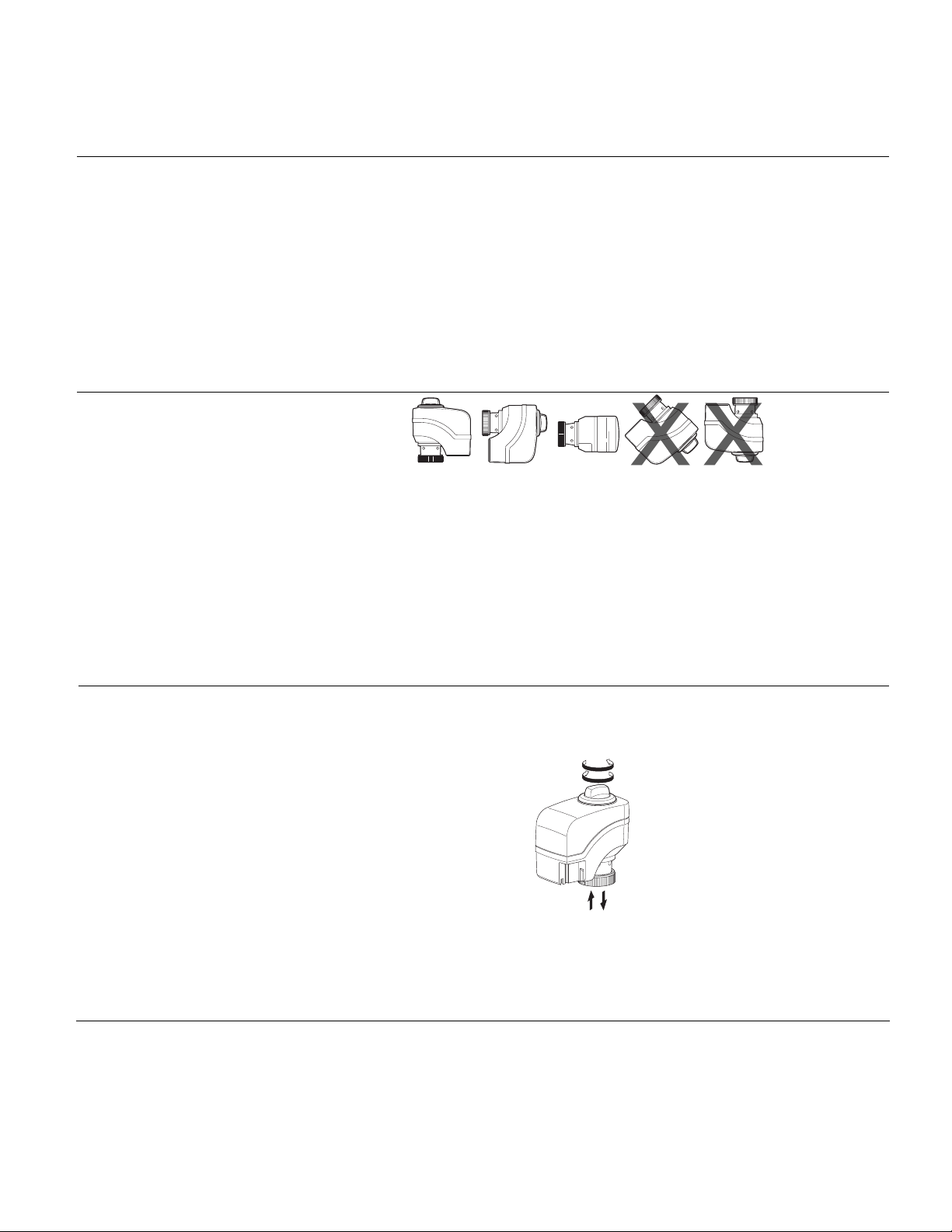
Figure 3. Mounting Positions.
Mount the actuator in one of the allowable positions shown in
Figure 3.
When mounting the actuator in a plenum, the proper cable must be attached to meet
local codes.
Allow 8 inches (200 mm) above the actuator and 8 inches (200 mm) behind the cable
for service.
Manual Override
Installation instructions are included with the actuator.
For manual positioning, turn the manual override knob in the center of the position
indicator. See
Figure 4. Turn clockwise to move the output shaft outward. The actuator
will maintain its position until power is provided or restored.
A
B
AB
EA0587R3
Figure 4. Manual Override.
NOTE: Do not perform manual override while the power supply is connected; the
actuator will not track accurately when the control signal is applied. A short
power off/power on sequence is recommended to recalibrate the actuator.
Siemens Industry, Inc. Page 3
Page 4
Technical Instructions Powermite 599 MZ Series SSB Electronic Valve Actuator
Document No. 155-192P25 24 Vac Proportional Control
Noember 25, 2013
Wiring
Do not use autotransformers. Use earth ground isolating step-down Class 2 power
supplies.
Determine supply transformer rating by summing total VA of all actuators used.
It is recommended that no more than 10 actuators be powered by one transformer.
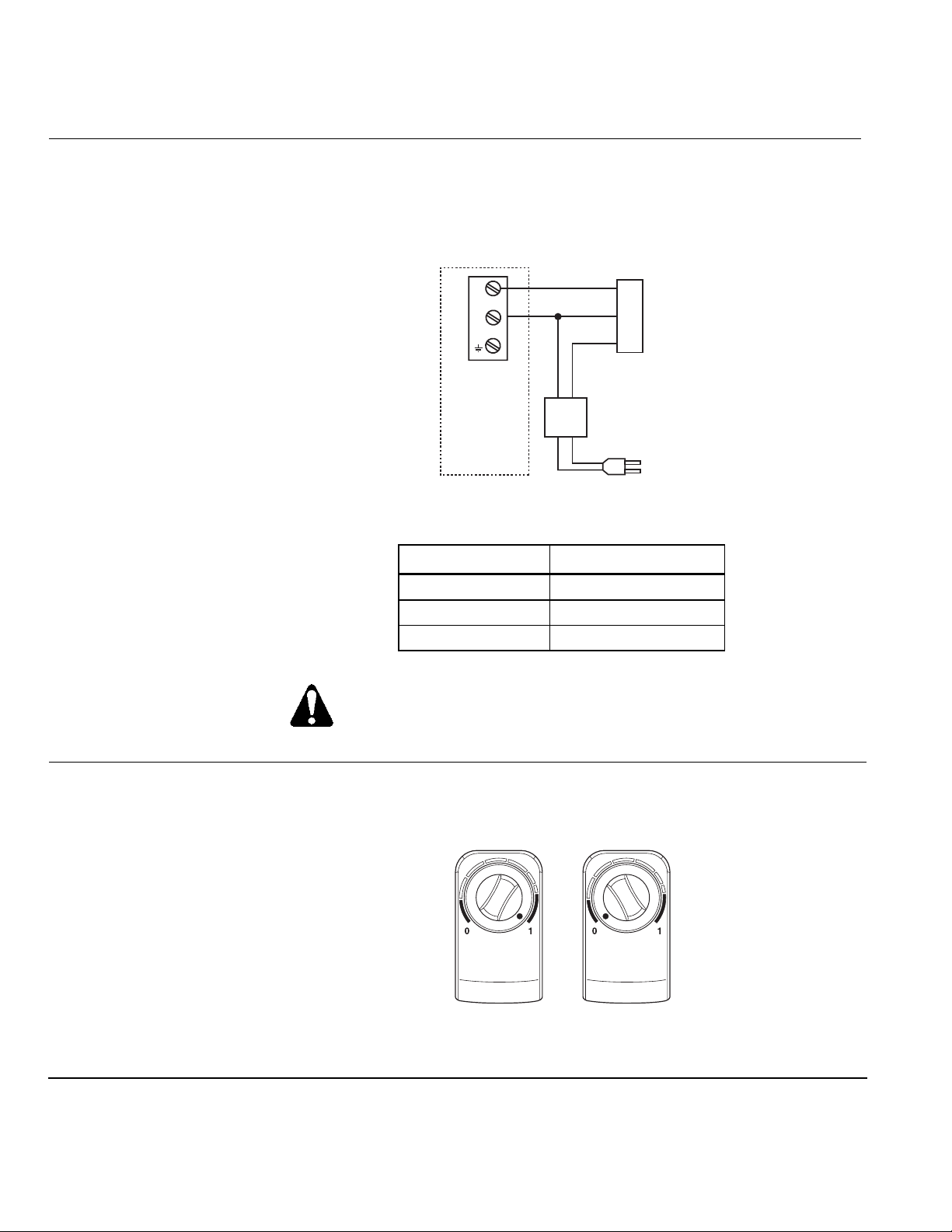
EA0069R3
+
-
A0-V BOARD
NEUT
Vac
Y
G0
G
24
EARTH GROUND
ISOLATING CLASS 2
TRANSFORMER FOR
24 Vac POWER
120 Vac
Figure 5. Terminal Connections of the SSB61U.
Function Terminal Connection
System potential G
System neutral G0
Control signal Y
WARNING:
Terminal connection “G0” is Common, not ground.
Start-Up
Check the wiring and the position indication.
When the position indicator is on the “1” position, the output shaft is extended.
When the position indicator is in the “0” position, the output shaft is retracted.
EA0588R3
Position indicator at 1 Position indicator at 0
Page 4 Siemens Industry, Inc.
Figure 6. Position Indicator.
Page 5
Powermite 599 MZ Series SSB Electronic Valve Actuator Technical Instructions
24 Vac Proportional Control Document No. 155-192P25
November 25, 2013
Troubleshooting
Service Kits
Dimensions
Check Wiring for proper connections.
If the actuator does not provide full flow or full close-off, check that the actuator is
properly attached to the valve. If not, turn power off, tighten the bonnet ring onto the
valve completely, and power up to recalibrate.
See Accessory and Service Kits for available accessory and service parts.
If the actuator is inoperative, replace the unit.
3-7/8
(98)
EA0589R2
3-1/4
(83)
3-1/8
(79)
1-7/8
(48)
Figure 7. Dimensions of the SSB Actuator in Inches (Millimeters).
Service Envelope
Minimum access space recommended:
8 inches (200 mm) above the actuator and beside the terminal plug.
Information in this publication is based on current specifications. The company reserves the right to make changes in specifications and models as
design improvements are introduced. Product or company names mentioned herein may be the trademarks of their respective owners.
© 2013 Siemens Industry, Inc.
Siemens Industry, Inc.
Building Technologies Division
1000 Deerfield Parkway
Buffalo Grove, IL 60089
USA
+ 1 847-215-1000
Your feedback is important to us. If you have
comments about this document, please send them to
Document No. 155-192P25
Printed in the USA
Page 5
 Loading...